1
F600
Step
3
>
Step
>
4
F
F
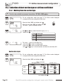
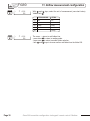
10. Airflow measurement configuration
607
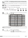
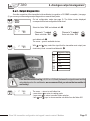
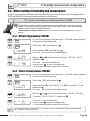
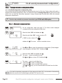
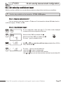
With and keys, enter the value (from 0 to 3000mm or 0 to 118.11 inch).
Validate with .
607
The cursor > returns to sub-folders line.
• press twice to return to reading mode.
• press once to return to another folder selection.
• with and keys, you can choose another sub-folder from the folder 600.
1500
1500
If you enter a length, width or diameter in mm, the transmitter will automatically calculate the conversion in Inch
(vice versa)
10.a.2 - Working from a airflow coefficient
With this coefficient, you can calculate the airflow from the pressure. This coefficient is given by the manufacturer of the
devices supplied with pressure connections (+ and -). From the square root of the pressure measured (Delta P),and from this
coefficient, you get the airflow.
Airflow = CD x
Pressure
!
Function only available for the pressure transmitter: CP 300 + SQR option. In this calculation mode, you
have no access to reading of air velocity. If you activate this calculation mode and also a channel in
air velocity, the transmitter will display an error code “4”.
!
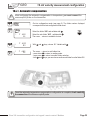
Go back to procedure page 28 / step 3:
With and keys, select 02 and validate with
Step
1
600
2
>
Step
3
>
Step
>
4
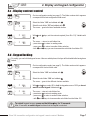
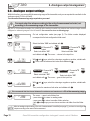
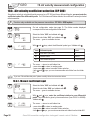
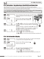
Go into configuration mode (see page 5). The folder number displayed
corresponds to the last configuration folder used.
100
Step
.
Select the folder “600” and validate with .
Select the sub-folder “613” and validate with
The cursor > goes to available choices.
db
Mo us
.
1226
F
613
00
F
613
With and
Validate with
F
614
01
The cursor > returns to sub-folders line.
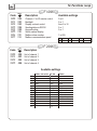
Select the sub-folder “614” to select the unit of measurement in
db
Mo us
pressure for the airflow calculation and validate with .
1228
The cursor > returns to available choices.
40.25
keys, enter the airflow coefficient value (from 0,01 to 999,99).
.
Class 300 transmitter configuration via keypad / remote control / Modbus
Page 29