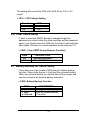
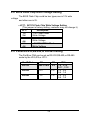
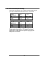
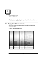
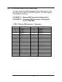
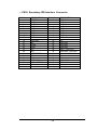
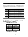
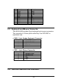
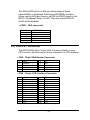
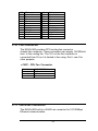
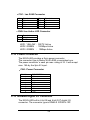
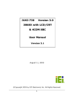
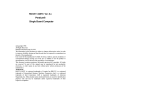
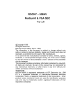
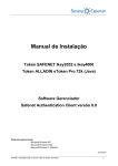
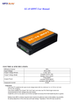
1
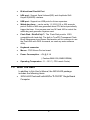
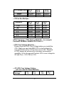
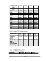
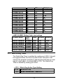
NOVA- 600 EBX Pentium®
Embedded Board
@Copyright 1998
All Rights Reserved.
Manual first edition Aug.01,1998
The information in this document is subject to change without prior notice in
order to improve reliability, design and function and does not represent a
commitment on the part of the manufacturer.
In no event will the manufacturer be liable for direct, indirect, special,
incidental, or consequential damages arising out of the use or inability to use
the product or documentation, even if advised of the possibility of such
damages.
This document contains proprietary information protected by copyright. All
rights are reserved. No part of this manual may be reproduced by any
mechanical, electronic, or other means in any form without prior written
permission of the manufacturer.
Trademarks
NOVA-600 is registered trademarks of Acquire Inc.,IBM PC is a registered
trademark of International Business Machines Corporation. Intel is a
registered trademark of Intel Corporation. AMI is registered trademarks of
American Megatrends, Inc. Other product names mentioned herein are used
for identification purposes only and may be trademarks and/or registered
trademarks of their respective companies.
Contents
1. Introduction .......................................................... 3
1.1
Specifications .............................................................................. 4
1.2
What You Have ........................................................................... 5
2. Installation ............................................................ 6
2.1
NOVA-600's Layout and Dimensions ........................................... 6
2.2
Setting the CPU of NOVA-600 ................................................... 9
2.3
Watch-Dog Timer ...................................................................... 11
2.4
DiskOnChip™Flash Disk ............................................................ 12
2.5
LCD Voltage Setting .................................................................. 13
2.6
Clear CMOS Setup ................................................................... 13
2.7
Battery Backup for CMOS Setup .............................................. 13
2.8
BIOS Flash Chip Write Voltage Setting .................................... 14
2.9
PortB RS-232,RS-422,or RS-485 Setting ................................. 14
2.10
PortC/PortD RI Pin Setting ....................................................... 15
3. Connection ......................................................... 16
3.1
Floppy Disk Drive Connector...................................................... 16
3.2
PCI E-IDE Disk Drive Connector ................................................ 17
3.3
Parallel Port............................................................................... 19
3.4
Serial Ports................................................................................ 19
1
3.5
Keyboard Connector .................................................................. 20
3.6
External Switches and Indicators ............................................... 21
3.7
USB Port Connector .................................................................. 21
3.8
IrDA Infrared Interface Port ....................................................... 22
3.9
LCD/CRT Connector ................................................................. 22
3.10 Fan Connector .......................................................................... 23
3.11
Lan RJ45 Connector ................................................................ 24
3.12
Power Connector ...................................................................... 24
3.13 Isolated Digital I/O Connector .................................................... 25
4. AMI BIOS Setup................................................. 28
4.1
Getting Start .............................................................................. 28
4.2
Standard CMOS Setup .............................................................. 29
4.3
Advanced CMOS Setup ............................................................. 30
4.4
Advanced Chipset Setup............................................................ 31
4.5
Peripheral Setup ....................................................................... 32
4.6
Power Management Setup ......................................................... 33
2
5. E Key Function .................................................. 34
Appendix A. Watch-Dog Timer .............................. 36
Appendix B. FP24-01 Module ................................ 37
2
Introduction
Welcome to the NOVA-600 EBX Pentium® Embedded Board.
The NOVA-600 board is an EBX form factor board, which comes
equipped with high performance Pentium® CPU and advanced
high performance LCD/CRT interface,10/100Mbps Ethernet..etc.
excellent features designed for the system manufacturers,
integrators, or VARs that want to provide all the performance,
reliability, and quality at a reasonable price.
This board built-in DiskOnChip™(DOC) Flash Disk for
embedded application. The DOC Flash Disk is 100% compatible
to hard disk. User can use any DOS command without any extra
software utility. The DOC currently is available from 2MB to
72MB.
An isolated digital I/O function is designed on the board. The
function provides 4-bit digital inputs and 4-bit digital outputs. It is
very useful in embedded application.
In addition, the NOVA-600 built-in C&T 65555 HiQPro™
LCD/CRT Chipset and 2MB EDO RAM. The LCD interface can
drive up to 1280x1024 with 256 colors. The support flat panel
will cover Color STN, TFT,EL,..etc. and also 3.3V or 5V version.
1.1 Specifications :
The NOVA-600 Pentium® with HiQPro™LCD/CRT Single Board
Computer provides the following specification:
•
CPU : Pentium® MMX up to 233Mhz, AMD K6 processor up to
300MHz, Cyrix 6x86MX and IDT C6 processor
3
•
Bus : ISA bus and PCI 32-bit local bus,PCI 2.1 standard
•
Chipset : ALI Alladin 4+
•
LCD/CRT Interface : C&T 655555 Chipset with 2MB EDO RAM
CRT Resolution : 1280x1024,256 colors
1024x768, 64K colors
800x600, 16M colors
36-bit LCD Interface Resolution :
1280x1024,256 colors
1024x768, 64K colors
800x600, 16M colors
Please contact www.chips.com to get more information.
•
Ethernet : Built-in the RTL8139 Chipset
IEEE 802.3u 100BASE-TX standard
Auto-sensing interface to 10MBps or 100MBps networks
Full duplex capability
More information :
www.realtek.com.tw
•
Real-time clock/calendar : in Alladin 4+ chipset,backup by
industrial Li-battery,3V/850mAH.
•
RAM memory : up to 128MB,SDRAM supported
•
Second Cache memory : 512KB Pipelined Burst SRAM on board
•
Ultra DMA/33 IDE Interface : up to four PCI Enhance IDE hard
drives. The Ultra DMA/33 IDE can handle data transfer up to
33MB/s. The best of all is that is new technology is compatible with
existing ATA-2 IDE specifications. So there is no need to do any
change for customer’ s current accessory.
•
Floppy disk drive interface : two 2.88 MB, 1.44MB, 1.2MB, 720KB,
or 360KB floppy disk drives.
•
Four high speed Series ports : NS16C550 compatible UARTs
4
•
Bi-directional Parallel Port
•
IrDA port : Support Serial Infrared(SIR) and Amplitude Shift
Keyed IR(ASKIR) interface.
•
USB port : Support two USB ports for future expansion.
•
Watch-dog timer : can be set by 1,2,10,20,110 or 220 seconds
period. Reset or NMI was generated when CPU did not periodically
trigger the timer. Your program use hex 043 and 443 to control the
watch-dog and generate a system reset.
•
Flash Disk - DiskOnChip™: The Flash Disk provide 100%
compatible with hard disk. The built-in TrueFFS Transparent Flash
Block Management and Space Reclamation will let customer to use
the Flash Disk with DOS command, no need any extra software
utility.
•
Keyboard connector
•
Mouse : PS/2 Mouse Port on-board.
•
Power Consumption : +5V @ 5.1A
( Pentium/MMX-200,32MB SDRAM)
•
Operating Temperature : 0° ~ 55° C ( CPU needs Cooler)
1.2 What You Have
In addition to this User's Manual, the NOVA-600 package
includes the following items:
• NOVA-600 Pentium® with HiQPro™LCD/CRT Single Board
Computer
5
2
Installation
This chapter describes how to install the NOVA-600. At first, the
layout of NOVA-600 is shown, and the unpacking information
that you should be careful is described. The jumpers and
switches setting for the NOVA-600's configuration, such as CPU
type selection, system clock setting, and watch dog timer, are
also included.
2.1 NOVA-600’ s Layout and Dimensions
< reference next page >
6
7
2.2 Setting the CPU of NOVA-600
• CPU Clock Setting :
8
CPU Speed/Clock
60MHz
66MHz
JP15
1-2
CLOSE
OPEN
JP15
9-10
OPEN
OPEN
JP15
11-12
OPEN
OPEN
• CPU to Bus Multiple :
Multiplier
1.5 x
2x
2.5x
3x
3.5 x
4x
4.5x
JP15
3-4
OPEN
CLOSE
CLOSE
OPEN
OPEN
CLOSE
CLOSE
JP15
5-6
OPEN
OPEN
CLOSE
CLOSE
OPEN
OPEN
CLOSE
JP15
7-8
OPEN
OPEN
OPEN
OPEN
OPEN
CLOSE
CLOSE
CPU Frequency = CPU Clock x Multiplier for example
Pentium® 200MHz = 66MHz CPU Clock x 3
• CPU Core Voltage Selection :
Please check the CPU Core Voltage before you install the
CPU. Right now new Intel MMX CPU is dual voltages for
core and I/O,the I/O is 3.3V but the core is 2.8V. This kind
of CPU design will enhance the low power consumption
capability. As for the general Pentium CPU is one voltage for
I/O and Core - 3.3V,3.4V,or 3.5V
• JP1 CPU Core Voltage Setting :
(JP1 is in the DC Power Module)
CPU Core
JP1
JP1
Voltage
1-2
3-4
9
JP1
5-6
JP1
7-8
3.5V(P54C/CS)
VRE
3.4V(P54C/CS)
STD
3.3V
3.2V
3.1V
3.0V
2.9V
2.8V
2.7V
2.6V
2.5V
2.4V
2.3V
2.2V
2.1V
2.0V
CLOSE
CLOSE
CLOSE
CLOSE
OPEN
CLOSE
CLOSE
CLOSE
CLOSE
OPEN
CLOSE
OPEN
CLOSE
OPEN
CLOSE
OPEN
CLOSE
OPEN
CLOSE
OPEN
CLOSE
OPEN
OPEN
OPEN
CLOSE
CLOSE
OPEN
OPEN
CLOSE
CLOSE
OPEN
OPEN
CLOSE
CLOSE
OPEN
OPEN
CLOSE
CLOSE
OPEN
OPEN
OPEN
OPEN
CLOSE
CLOSE
CLOSE
CLOSE
OPEN
OPEN
OPEN
OPEN
CLOSE
CLOSE
CLOSE
CLOSE
CLOSE
CLOSE
OPEN
OPEN
OPEN
OPEN
OPEN
OPEN
OPEN
OPEN
• Dual / Single CPU Voltage setting :
Vcore & VIO
Pentium®
(P54C)
IDT C6
Pentium®
MMX
AMD K6
Cyrix 6x86MX
Dual Voltage
JP13
1-2
CLOSE
JP13
3-4
CLOSE
JP14
1-2
OPEN
JP14
3-4
OPEN
OPEN
OPEN
CLOSE
CLOSE
• Cyrix 6x86MX PR Rating Table
( Vcore : 2.9V,dual voltage )
PR Rating
Bus MHz CPU Core
10
Clock
6x86MX-PR133
6x86MX-PR133
6x86MX-PR150
6x86MX-PR150
6x86MX-PR166
6x86MX-PR166
6x86MX-PR166
6x86MX-PR166
6x86MX-PR200
6x86MX-PR200
6x86MX-PR200
6x86MX-PR233
6x86MX-PR266
50
55
60
50
66
55
50
60
55
66
60
66
66
MHz
100
110
120
125
133
138
150
150
165
166
180
200
233
Multiplier
2x
2x
2x
2.5x
2x
2.5x
3x
2.5x
3x
2.5x
3x
3x
3.5x
• AMD K6 MMX Rating Table, dual voltage
Product Name
Core
Vcore Bus MHz Multiplier
Freq
K6-233 model 6 233MHz 3.2V
66
3.5x
K6-200 model 6 200MHz 2.9V
66
3x
K6-166 model 6 166MHz 2.9V
66
2.5x
K6-300 model 7 300MHz 2.2V
66
4.5x
K6-266 model 7 266MHz 2.2V
66
4x
K6-233 model 7 233MHz 2.2V
66
3.5x
2.3 Watch-Dog Timer
The Watch-Dog Timer is enabled by reading port 443H. It should
be triggered before the time-out period ends, otherwise it will
assume the program operation is abnormal and will issue a reset
signal to start again, or activate NMI to CPU. The Watch-Dog
Timer is disable by reading port 043H.
• JP18 : Watch-Dog Active Type Setting
JP18
DESCRIPTION
2-3
RESET WHEN WDT TIME-OUT
11
1-2
OPEN
ACTIVATE NMI TO CPU WHEN WDT TIMEOUT
DISABLE WDT
• JP11: WDT Time-Out Period
PERIOD
1-2
3-4
OPEN
OPEN
1 sec.
OPEN
OPEN
2 sec.
10 sec.
OPEN
CLOSE
OPEN
CLOSE
20 sec.
110 sec. CLOSE OPEN
220 sec. CLOSE OPEN
5-6
CLOSE
CLOSE
OPEN
OPEN
OPEN
OPEN
7-8
OPEN
CLOSE
OPEN
CLOSE
OPEN
CLOSE
2.4 DiskOnChip™Flash Disk
The DiskOnChip™Flash Disk Chip(DOC) is produced by
M-Systems. Because the DOC is 100% compatible to hard disk
and DOS.Customer don‘ t need any extra software utility. It is
just “ plug and play” ,easy and reliable.
• JP16 : DiskOnChip Memory Address Setting
Address
JP16
1-2
CE000
D6000
3-4
5-6
DE000
2.5 LCD Voltage Setting
The NOVA-600 supports 3.3V or 5V LCD panel by jumper setting.
12
The setting will control the CN5’ s Pin 29 & 30 as 3.3V or 5V
output.
• JP10 : LCD Voltage Setting
Function
3.3V
5V
JP10
1-2
2-3
2.6 Clear CMOS Setup
If want to clear the CMOS Setup(for example forgot the
password you should clear the setup and then set the password
again.),you should close the CN26 pin 3-4 about 3 seconds,then
open again. Set back to normal operation mode,close pin 2-3.
• CN26 : Clear CMOS Setup (Reserve Function)
CN26
2-3
3-4
DESCRIPTION
Normal Operation
Clear CMOS Setup
2.7 Battery Backup for CMOS Setup
There have one 4-pin header CN26 using for battery backup
function. When close the pin 2-3 will use the on board battery.
When use external battery you should take off the jumper and
use the connector as external battery connector.
• CN26: Battery Backup Function
CN26
2-3 CLOSE
1- Vbat
4- Ground
DESCRIPTION
Using Internal Battery
Use as External Battery
Connector
13
2.8 BIOS Flash Chip Write Voltage Setting
The BIOS Flash Chip could be two types,one is 12V write
voltage
and other one is 5V.
• JP17 : 5V/12V Flash Chip Write Voltage Setting
(This jumper is factory setting ,customer may not change it)
JP17
Description
+12V 1Mbit Flash
1-3
Write Voltage
2-4
+12V 1Mbit/2Mbit Flash
1-3
Write Voltage
4-6
3-5
+5V 1Mbit/2Mbit Flash
4-6
Write Voltage
2.9 PortB RS-232,RS-422,or RS-485 setting
The PortB on CN6 can be set as RS-232,RS-422,or RS-485
mode by the JP4,JP6,or JP12.
PortB Mode
RS-232
JP4
Don’ t care
JP6
2-3
RS-422
2-3
1-2
RS-485
1-2
1-2
14
JP12
1-9 , 3-10
5-11 , 7-12
1-2 , 3-4
5-6 , 7-8
1-2 , 3-4
5-6 , 7-8
2.10 PortC/PortD RI pin setting
The PortC’ s RI pin(pin 19) on CN7 and the PortD’ s RI pin
(pin 19) on CN6 can be set as RI,+5V,or +12V mode.
PortC
CN7 Pin 19
RI
+5V
+12V
JP1
PortD
CN6 Pin 19
RI
+5V
+12V
JP2
JP3
2-3
1-2
1-2
Don’ t Care
1-2
2-3
JP21
2-3
1-2
1-2
Don’ t Care
1-2
2-3
Please note when set the +12V ouput, the board
should have +12V input from power supply by the
CN4 power connector.
15
3
Connection
This chapter describes how to connect peripherals, switches and
indicators to the NOVA-600 board.
3.1 Floppy Disk Drive Connector
NOVA-600 board equipped with a 34-pin daisy-chain driver
connector cable.
• CN11: FDC CONNECTOR
PIN NO.
1
3
5
7
9
11
13
15
17
19
21
23
25
27
29
31
33
DESCRIPTION
GROUND
GROUND
GROUND
GROUND
GROUND
GROUND
GROUND
GROUND
GROUND
GROUND
GROUND
GROUND
GROUND
GROUND
GROUND
GROUND
GROUND
PIN NO.
2
4
6
8
10
12
14
16
18
20
22
24
26
28
30
32
34
16
DESCRIPTION
REDUCE WRITE
N/C
N/C
INDEX#
MOTOR ENABLE A#
DRIVE SELECT B#
DRIVE SELECT A#
MOTOR ENABLE B#
DIRECTION#
STEP#
WRITE DATA#
WRITE GATE#
TRACK 0#
WRITE PROTECT#
READ DATA#
SIDE 1 SELECT#
DISK CHANGE#
3.2 PCI E-IDE Disk Drive Connector
You can attach four IDE( Integrated Device Electronics) hard
disk drives to the NOVA-600 IDE controller. The IDE support
Ultra DMA/33 interface.
CN13(IDE 1) : Primary IDE Connector,2.54mm pitch
CN10(IDE 2) : Secondary IDE Connector,2.0mm pitch
for 2.5” IDE HDD
• CN13: Primary IDE Interface Connector
PIN NO.
1
3
5
7
9
11
13
15
17
19
21
23
25
27
29
31
33
35
37
39
DESCRIPTION
RESET#
DATA 7
DATA 6
DATA 5
DATA 4
DATA 3
DATA 2
DATA 1
DATA 0
GROUND
N/C
IOW#
IOR#
N/C
N/C
INTERRUPT
SA1
SA0
HDC CS0#
HDD ACTIVE#
PIN NO.
2
4
6
8
10
12
14
16
18
20
22
24
26
28
30
32
34
36
38
40
17
DESCRIPTION
GROUND
DATA 8
DATA 9
DATA 10
DATA 11
DATA 12
DATA 13
DATA 14
DATA 15
N/C
GROUND
GROUND
GROUND
BALE - DEFAULT
GROUND - DEFAULT
IOCS16#-DEFAULT
N/C
SA2
HDC CS1#
GROUND
• CN10: Secondary IDE Interface Connector
PIN NO.
1
3
5
7
9
11
13
15
17
19
21
23
25
27
29
31
33
35
37
39
41
43
DESCRIPTION
RESET#
DATA 7
DATA 6
DATA 5
DATA 4
DATA 3
DATA 2
DATA 1
DATA 0
GROUND
N/C
IOW#
IOR#
N/C
N/C
INTERRUPT
SA1
SA0
HDC CS0#
HDD ACTIVE#
+5V
Ground
PIN NO.
2
4
6
8
10
12
14
16
18
20
22
24
26
28
30
32
34
36
38
40
42
44
18
DESCRIPTION
GROUND
DATA 8
DATA 9
DATA 10
DATA 11
DATA 12
DATA 13
DATA 14
DATA 15
N/C
GROUND
GROUND
GROUND
BALE - DEFAULT
GROUND - DEFAULT
IOCS16#-DEFAULT
N/C
SA2
HDC CS1#
GROUND
+5V
Pull High
3.3 Parallel Port
This port is usually connected to a printer, The NOVA-600 includes an
on-board parallel port, accessed through a 26-pin flat-cable connector
CN8.
• CN8 : Parallel Port Connector
PIN NO.
1
3
5
7
9
11
13
15
17
19
21
23
25
DESCRIPTION
STROBE#
DATA 1
DATA 3
DATA 5
DATA 7
BUSY
PRINTER SELECT
ERROR#
PRINTER SELECT LN#
GROUND
GROUND
GROUND
GROUND
PIN NO.
2
4
6
8
10
12
14
16
18
20
22
24
DESCRIPTION
DATA 0
DATA 2
DATA 4
DATA 6
ACKNOWLEDGE
PAPER EMPTY
AUTO FORM FEED #
INITIALIZE
GROUND
GROUND
GROUND
GROUND
3.4 Serial Ports
The NOVA-600 offers four high speed NS16C550 compatible UARTs
with Read/Receive 16 byte FIFO serial ports.
• CN6(PorB,PortD) : 20-pin Header
Pin
1
2
3
4
5
6
7
8
9
10
Description
DCD2/TX2RXD2/TX2+
TXD2
DTR2
GND
DCD4
RXD4
TXD4
DTR4
GND
Pin
11
12
13
14
15
16
17
18
19
20
Description
DSR2/RX2+
RTS2/RX2CTS2
RI2
NC
DSR4
RTS4
CTS4
RI,+5V,or +12V
NC
• CN7(PortA,PortC) : 20-pin Header
19
Pin
1
2
3
4
5
6
7
8
9
10
Description
DCD1
RXD1
TXD1
DTR1
GND
DCD3
RXD3
TXD3
DTR3
GND
Pin
11
12
13
14
15
16
17
18
19
20
Description
DSR1
RTS1
CTS1
RI
NC
DSR3
RTS3
CTS3
RI,+5V,or +12V
NC
3.5 Keyboard and Mouse Connector
The NOVA-600 provides 5-pin keyboard and mouse connectors.
The connector is 2.5mm pitch model Say Yea 2570-05P or
equivalent one.
• CN20 : 5-pin Header Keyboard Connector
PIN NO.
1
2
3
4
5
DESCRIPTION
KEYBOARD CLOCK
KEYBOARD DATA
N/C
GROUND
+5V
• CN21 : 5-pin Mouse Connector
PIN NO.
1
2
3
4
5
3.6
DESCRIPTION
MOUSE CLOCK
MOUSE DATA
N/C
GND
+5V
External Switches and Indicators
20
There are many external switches and indicators for monitoring
and controlling your CPU board.
• CN15 : Reset Connector
PIN NO.
1
2
DESCRIPTION
RESET SIGNAL
GROUND
• CN2 : Speaker Connector
PIN NO.
1
2
DESCRIPTION
+5V
SPEAKER
• CN25 : IDE LED Connector
PIN NO.
1
2
DESCRIPTION
+5V
HDD ACTIVE#
• CN22 : KeyLock & Power
PIN NO.
1
2
3
4
5
DESCRIPTION
+5V
N/C
GROUND
KEYLOCK
GROUND
3.7 USB Port Connector
The NOVA-600 built-in two USB ports for the future new I/O bus
expansion.
• CN18 : USB 0/1
1
3
5
7
+5V
D0D0+
GND
2
4
6
8
GND
D1+
D1+5V
3.8 IrDA Infrared Interface Port
21
The NOVA-600 built-in a IrDA port which support Serial
Infrared(SIR) or Amplitude Shift Keyed IR(ASKIR) interface.
When use the IrDA port have to set SIR or ASKIR model in the
BIOS’ s Peripheral Setup’ s PortD. Then the normal RS-232
PortD will be disabled.
• CN23 : IrDA connector*
PIN NO.
1
2
3
4
5
DESCRIPTION
VCC
NC
IR-RX
Ground
IR-TX
3.9 LCD/CRT Connector
The NOVA-600 built-in 10-pin VGA connector directly to your
CRT monitor. And the built-in 50-pin connector for LCD interface.
• CN9 : 10-pin VGA Header Connector
1
2
3
4
5
RED
GREEN
BLUE
HSYNC
VSYNC
6
7
8
9
10
N/C
N/C
GROUND
GROUND
GROUND
• CN5 : 50-pin LCD Interface Connector
1
3
5
7
9
11
13
15
17
19
21
23
25
VPCLK
P34
P35
P30
P29
P25
P24
P23
P16
P17
P19
P13
P15
2
4
6
8
10
12
14
16
18
20
22
24
26
P33
P31
P32
P28
P27
P26
P21
P22
P20
P18
P14
P12
P11
22
27
29
31
33
35
37
39
41
43
45
47
49
P7
5V or 3.3V
P9
P4
P3
P2
M
SHFCLK
FPVDD
FPVEE
GND
+12V
28
30
32
34
36
38
40
42
44
46
48
50
P10
5V or 3.3V
P8
P6
P5
P1
P0
ENABKL`
FLM(V SYS)
LP(H SYS)
GND
+12V
3.10 Fan Connector
The NOVA-600 provides CPU cooling fan connector,
chassis fan connector. These connectors can supply 12V/500mA
max. to the cooling fan. The 12V on the fan connector is
converted from 5V,so it is limited in fan using. Don’ t use it for
other purpose.
• CN27 : CPU Fan Connector
PIN NO.
1
2
3
DESCRIPTION
N/C
12V
Ground
3.11 Lan RJ45 Connector
The NOVA-600 built-in a RJ45 Lan connector for 10/100Mbps
Ethernet communication.
23
• CN1 : Lan RJ45 Connector
Pin
1
2
3.
4.
Description
TX+
TXRX+
NC
Pin
5.
6.
7.
8.
Description
NC
RXNC
NC
• CN24 Lan Active LED Connector
Pin.
1.
2.
Description
5V
RX/TX
LED1 YELLOW : RX/TX Active
LED2 GREEN : 100Mbps Active
LED3 GREEN : 10Mbps Active
3.12 Power Connector
The NOVA-600 provides a 8-pin power connector,
The connector type is Molex 26-60-4080 or equivalent one.
The power connector’ s each pin max. rating is 7A. It will accept
max. 14A by the 2pin 5V input.
• CN4 : Power Connector
PIN NO.
1
2
3
4
5
6
7
8
DESCRIPTION
+5V
Ground
Ground
+12V
N/C
Ground
+5V
-12V
3.13 Isolated Digital I/O Connector
The NOVA-600 built-in 4-bit IN and 4-bit OUT digital I/O
connector. The connector type is DINKLE ED350V-10P.
24
Because this is isolated Digital I/O design , it will need an
external power supply to the connector’ s Pin 9 and Pin10 to
active the circuit. You may refer the following block diagram to
know the details. The external power supply’ s DC output should
be not connected with the NOVA-600’ s power supply at either
5V,12V or ground to isolate the NOVA-600 main system and the
external I/O device.
In case you could not find an external power supply to active the
Digital I/O,you may use the 5V or 12V from the system’ s power
supply. Under the situation the digital I/O function will be not
isolated.
• CN14 : DIO Connector
Pin#
1
2
3
4
5
6
7
8
9
10
Signal Name
IN00
IN01
IN02
IN03
OUT00
OUT01
OUT02
OUT03
COM COM +
Function
Data IN
Data IN
Data IN
Data IN
Data OUT
Data OUT
Data OUT
Data OUT
External Power Ground
External Power 5 – 30V
The digital I/O are addressed at 220H,240H,260H,or Disable
through CMOS peripheral setup selection. You may refer the
following table for the address and matching I/O port.
Bit 0 Bit 1 Bit 2 Bit 3 Bit 4
Bit 5
Bit 6
Bit 7
IN00 IN01 IN02 IN03 OUT00 OUT01 OUT02 OUT03
The Digital Input specifications are :
Isolated channel with common power
25
Digital input level
Logic level 0 : +1V max.
Logic level 1 : +3.5V to 30V
Input impedance : 3K ohm ,0.5W
The Digital Output specifications are :
Isolated channel with common power
Open collector to 30V
Output current : 600mA per channel, total 3A max.
• Windows 95/NT Driver for DIO application
The WDT-01 Windows 95/NT software utility are included in
the
CD ROM. From the WDT-01 utility you may use the DIO.H ,
DIO.LIB, and DIO.DLL for the digital I/O application.
The software user manual are also in the CD ROM. You may
print it out for better reference.
26
27
4
AMI BIOS Setup
The NOVA-600 uses the AMI BIOS for system configuration.
The AMI BIOS setup program is designed to provide maximum
flexibility in configuring the system by offering various options
which may be selected for end-user requirements. This chapter
is written to assist you in the proper usage of these features.
4.1 Getting Start
When power on the system, the BIOS will enter the Power-OnSelf-Test routines. These routines will be executed for system
test and initialization and system configuration verification. After
the POST routines are completed, the following message
appears :
" Hit DEL if you want to run SETUP"
To access AMI BIOS Setup program, press <Del> key,then you
could see the screen to make some options as follows,
When choose Load BIOS Defaults will load the minimized
settings for Troubleshooting. The performance should be very
poor when use this setting.
When choose Load Setup Defaults will load optimized defaults
for regular use. Choosing this setting, will modify all applicable
settings.
28
4.2 Standard CMOS Setup
The Standard CMOS Setup is used for basic hardware system
configuration. The main function is for Date/Time setting and
Floppy/Hard Disk Drive setting. Please refer the following screen
for this setup.
For IDE hard disk drive setup, please check the following
possible
setup procedure,
1. Use the Auto setting for detection during bootup.
2. Use the IDE HDD AUTO DETECTION in the main menu to
automatically enter the drive specifications.
3. Manually enter the specifications by yourself from
the ” User“ option.
29
4.3 Advanced CMOS Setup
This Advanced CMOS Setup is designed for customer‘ s tuning
best performance of the NOVA-600 board. As for normal
operation customers don‘ t have to change any default setting.
The default setting is pre-set for most reliable operation.
You also can option the system keyboard,primary display,PS/2
mouse to enable or disable.
The system boot sequence is also set here by first,second,third
and fourth boot device setting.
4.4 Advanced Chipset Setup
30
This setup functions are almost working for ChipSet(ALI
4+). These options are used to change the ChipSet‘ s registers.
Please carefully change any default setting ,otherwise the
system could be running un-stable.
Auto Configuration : Enable or Disable
When use the 60nS general type DRAM,please enable the
setting to get the optimal timings.
SDRAM Speculative Read : Enable or Disable
When enable this option, the PCU will send predict commands
to the SDRAM, if a miss happens, the CPU will cancel this
command. Because some OS under certain situations have
problem for this feature, it is normally disable.
4.5 Peripheral Setup
31
This setup is almost working for Multi-I/O Chip(W83877F and
ALI Alladin 4+ chipset). These options are used to change the
ChipSet‘ s registers. Please carefully change any default setting
to meet your application need perfectly. The only special
concern is Onboard Serial PortD. If you are using the IrDA
port,you have to set this port accordingly.
Customer also can set the Isolated Digital I/O function’ s I/O
addressing here by 220h,240h,260h,or disable.
The most important setting in this setup is LCD Type setting. In
the most right bottom item – Panel Type selection, customer can
choose 15 different panel type. The 15 panel types are :
1.
2.
3.
4.
5.
6.
7.
8.
9.
10.
11.
12.
13.
14.
15.
1024x768 Dual Scan STN Color
1280x1024 TFT
640x480 STN
800x600 STN
640x480 TFT
640x480 18bit
1024x768 TFT
800x600 TFT
800x600 TFT
800x600 TFT
800x600 STN
800x600 STN
1024x768 TFT
1280x1024 STN
1024x600 STN
4.6 Power Management Setup
32
Power Management Setup help user handles the NOVA-600
board‘ s “ green” function. The features could shut down the
video display and hard disk to save energy for example. The
power management setup screen is as following,
Power Management/APM : Disable, Max Saving, Min Saving,
or User Defined
Note : Advanced Power Management(APM) have to be
installed to keep the system time updated when the computer
enters suspend mode activated by the Power Management.
Under DOS environment, you need to add
DEVICE=C:\DOS\POWER.EXE in your CONFIG.SYS
Under Windows 3.x and Windows 95,you have to install
Windows with APM feature. A battery and power cord icon
labeled “ Power”
Will appear in the “ Control Panel”
33
5
2
E Key™Function
2
The NOVA-600 provides an outstanding E KEY™function for
2
system integrator. Based on the E KEY™you could free to store
the ID Code, Pass Word, or Critical Data in the 1Kbit EEPROM.
Because the EEPROM is nonvolatile memory, you don’ t have to
worry the losing of the very important data.
2
Basically the E KEY™is based on a 1Kbit EEPROM which is
configured to 64 words(from 0 to 63). You could access(read or
write) each word at any time.
2
When you start to use the E KEY™you should have the utility in
the package. The software utility will include four files as follows,
README.DOC
E2KEY.OBJ
EKEYDEMO.C
EKEYDEMO.EXE.
The E2KEY.OBJ provides two library function for user to
2
integrate their application with E KEY™function. These library
(read_e2key and write_e2key) are written and compiled in C
format. Please check the following statement, then you will know
how to implement it easily.
34
unsigned int read_e2key(unsigned int address)
2
/* This function will return the E KEY™
’ s data at address. The
address range is from 0 to 63. Return data is one word,16 bits */
void write_e2key(unsigned int address,unsigned data)
2
/* This function will write the given data to E KEY™at address.
The address range is from 0 to 63. The data value is from 0 to
0xffff. */
To easy start to use the function, please refer the include
EKEYDEMO.C code at first.
2
Please note the E KEY™function is based on the working of
parallel port. So you should enable the NOVA-600’ s parallel port,
otherwise will be not working.
Appendix A. Watch-Dog Timer
35
The Watch-Dog Timer is provided to ensure that standalone
systems can always recover from catastrophic conditions that
caused the CPU to crash. This condition may have occurred by
external EMI or a software bug. When the CPU stops working
correctly, hardware on the board will either perform a hardware
reset (cold boot) or a non-maskable interrupt (NMI) to bring the
system back to a known state.
The Watch-Dog Timer is controlled by two I/O ports.
443
Read
Enable the refresh the Watch-Dog
(hex)
Timer.
043
Read
Disable the Watch-Dog Timer.
(hex)
To enable the Watch-Dog Timer, a read from I/O port 443H
must be performed. This will enable and activate the countdown
timer which will eventually time out and either reset the CPU or
cause an NMI depending on the setting of JP18. To ensure that
this reset condition does not occur, the Watch-Dog Timer must
be periodically refreshed by reading the same I/O port 433H.
This must be done within the time out period that is selected by
jumper group JP11.
A tolerance of at least 30% must be maintained to avoid
unknown routines within the operating system (DOS), such as
disk I/O that can be very time consuming. Therefore if the time
out period has been set to 10 seconds, the I/O port 443H must
be read within 7 seconds.
Note: when exiting a program it is necessary to disable the WatchDog Timer, otherwise the system will reset.
Appendix B. FP24-01 Flat Panel
Connection Module
36
The FP24-01 connection module is installed on the NOVA-600
as a standard product. The FP24-01 converts NOVA-600’ s on
board 50pin LCD interface signal to the 44-pin (2x20 pin header)
and 41pin (Hirose DF9-41P-1V) LCD connectors. The 44-pin or
41-pin connector will only support 24-bit flat pane.
• J3 : 44-pin LCD Interface Connector
1
3
5
7
9
11
13
15
17
19
21
23
25
27
29
31
33
35
37
39
41
43
+12V
GND
5V or 3.3V
FPVEE
P0
P2
P4
P6
P8
P10
P12
P14
P16
P18
P20
P22
GND
SHFCLK
M
GND
N/C
FPVDD
2
4
6
8
10
12
14
16
18
20
22
24
26
28
30
32
34
36
38
40
42
44
+12V
GND
5V or 3.3V
GND
P1
P3
P5
P7
P9
P11
P13
P15
P17
P19
P21
P23
GND
FLM
LP
ENABKL
N/C
5V or 3.3V
• J1 : 41-pin LCD Interface Connector
1
P20
2
GND
37
3
5
7
9
11
13
15
17
19
21
23
25
27
29
31
33
35
37
39
41
P16
P21
P17
P22
P18
P23
P19
5V or 3.3V
FLM
M
LP
SHFCLK
5V or 3.3V
5V or 3.3V
ENABKL
FPVDD
FPVEE
GND
GND
N/C
4
6
8
10
12
14
16
18
20
22
24
26
28
30
32
34
36
38
40
5V or 3.3V
P0
P8
P1
P9
P2
P10
P3
P11
P4
P12
P5
P13
P6
P14
P7
P15
+12V
+12V
• J2 : LCD Backlight Power Connector*
PIN NO.
1
2
3
4
5
DESCRIPTION
N/C
GND
12V (0.9A max.)
GND
FPVEE
Inverter Enable
38