1
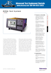
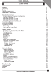
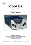
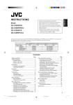
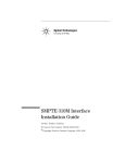
M P E G Te s t a n d M o n i t o r i n g
MTS300
Features & Benefits
Real-time Monitoring and
Compliance Testing of
MPEG, DVB, ATSC and
ISDB Transport Streams
for Complete Application
Flexibility
Status and Error Logging
for Capturing Intermittent
Problems or Creating
Test Records
Dolby Digital AC-3
Compliance Testing and
AAC Stream Monitoring
for Testing Advanced
Audio Capabilities
Tektronix-exclusive PCR
Overall Jitter, Drift and
Offset Measurements Allow
You to Diagnose the Most
Challenging Real-time
Performance Problems
Detailed Off-line Analysis of
Transport Streams, Program
Streams and Elementary
Streams Available to Fully
Verify Design Performance
The Tektronix MTS300 MPEG Test System
is a high-performance MPEG protocol diagnostic and analysis tool giving you innovative solutions to meet the challenges of
designing, verifying and characterizing
products and systems using MPEG-2 technology. The MTS300 offers powerful acquisition and computational capabilities for
analyzing designs based on MPEG, DVB,
ATSC and ISDB standards. These flexible
and expandable capabilities include realtime monitoring, data rate analysis and
Tektronix-exclusive timing analysis to help
diagnose the most challenging problems
and characterize real-time performance.
In-depth, deferred-time (off-line) analysis
helps fully verify compliance to standards
and diagnose problems in complex transport streams. Easy-to-use transport stream
capture, playout and on-line storage let you
build extensive suites of test streams and
use these streams to exercise your designs.
1
MPEG Test • www.tektronix.com/video
Additional stream editing capability, with
error and jitter injection and real-time multiplexing, gives you the ability to create and
playout test sequences that fully stress and
characterize design parameters.
Real-time Monitoring
The MTS300 uses intuitive icons and
colors to indicate the current status of
MTS300 I/O ports and any MPEG transport
stream under analysis. A simple, easy-touse display indicates:
The current usage and status of the
MTS300 I/O ports. You can install
up to four I/O ports on an MTS300
The current status of monitored transport
streams and the programs within monitored
transport streams. Highly visible indicators
let you quickly identify the transport stream
or program with problems
The type of problem detected in a
monitored transport stream. Intuitive
icons show problems in transport stream
protocol, timing errors, or problems in the
video or audio elementary streams
ASI/M2S, SPI (LVDS),
SMPTE310M and DHEI
Interfaces Available to
Support a Variety of
Design Configurations
Capture, Playback and
On-line Storage of
Transport, Program and
Elementary Streams
Optional Editing Capability
Allows You to Create Custom
Transport Streams and Inject
Errors or Jitter to Fully Stress
Your Design
Modular Architecture
Lets You Purchase the
Performance You Desire
Today. You Can Easily
Upgrade in the Future as
Your Needs Change
Applications
Evaluation and Verification
of MPEG, DVB, ATSC and
ISDB Designs
Design and Verification of
Digital Video Set-top Boxes
(STBs)
Stress and Characterization
of Circuits and ICs
Developed for Products
Using MPEG-2 Compressed
Digital Video Technology
MPEG Test and Monitoring
MTS300
Using this display, you can easily configure
and control the product in real-time testing
applications, to quickly identify and diagnose problems with designs or to characterize design or system performance.
The MTS300 Master Client
The MTS300 Master Client application
controls real-time testing operations and
displays status information organized into
three panels.
Port Manager Panel. The Port Manager
lets you configure and control the MTS300
I/O ports. You can assign an application
server to these ports that either monitors
or captures the transport stream present at
the MTS300 input interface associated with
the I/O port, or plays out a transport stream
at the MTS300 output interface associated
with the I/O port. Different icons represent
the different ports and application services.
For monitored transport streams, red icons
let you immediate identify the transport
stream experiencing problems.
Services Panel. The Services panel displays the status of each program or service
in the monitored transport stream selected
in the Port Manager panel. Different icons
represent different programs or services.
The same red icon indicates a service
experiencing problems.
2
MPEG Test • www.tektronix.com/video
Details Panel. The Details panel displays
the types of problems the MTS300 detected,
and changes views depending on whether
you select a transport stream or a service
within a transport stream:
If you select a monitored transport stream
icon, the displayed icons represent transport
stream error types, e.g., problems in system
information tables
If you select a service icon, the displayed
icons represent service error types, e.g.,
errors in the video or audio programs
In both modes, intuitive icons represent
error types: a clock for PCR and PTS/DTS
timing errors, a speaker for errors in audio
services and a video recorder for errors
in video services.
Real-time Analysis
In addition to being an MPEG-2 protocol
monitor, the MTS300 gives you powerful
real-time analysis capability to help diagnose
difficult real-time performance problems.
The MTS300 real-time analysis capabilities
include:
The evaluations recommended by DVB
standard TR 101 290 to verify decodability,
quality and reliability
Tektronix-exclusive timing analysis, including
PCR overall jitter and wander measurements
Flexible, intuitive displays of data rates
and program allocations
Figure 1. Typical 3-panel Master Client
screen. This screen displays the error status
for the monitored MPEG transport stream
and monitored services within the stream.
Analysis of Mega-frame Initialization
packets used in DVB-T Single Frequency
Network applications
Real-time analysis of transport streams
used in data broadcasting applications
based on ISO/IEC 13818-6 (DSM-CC)
and EN 301 192 standards
Fully selectable monitoring depth, fault
criteria, and error reporting and alarms
Triggered capture of transport streams
for later in-depth analysis
Status and error logging
MTS300 Expert and
Configuration Clients
To begin real-time analysis, you select a
monitored transport stream or service in the
Master Client and launch an MTS300 Expert
Client. The Expert Client opens with a display
of real-time analysis results on the transport
stream. This tight integration lets you
quickly detect problems with the Master
Client, then open an Expert Client for more
in-depth analysis.
MPEG Test and Monitoring
MTS300
TR 101 290
Measurement Display
Figure 3. PCR analysis.
Figure 2. Typical Expert Client screen.
This screen displays information and
analysis results of the monitored MPEG
transport stream.
The Expert Client “status-at-a-glance”
display (Figure 2) lets you quickly determine
the overall bandwidth and efficiency of the
transport stream under analysis. Dynamic
graphic displays show data rates, percentage
of use, and global data information on each
program, PID, and the overall transport
stream. The Hierarchy View displays the
structure of the monitored transport stream,
and the Report View displays analysis results.
The various views in the MTS300 use color
to help you easily understand analysis
results. Green indicates a passing condition
for a particular analysis, red indicates a
current failure and orange indicates a failure
condition has occurred in the past, but is
no longer present. You can view analysis
results for the overall stream in the Report
View or select a specific PID in the
Hierarchy View and display analysis results
on only this selected PID.
The Expert Client offers two views for displaying the results of TR 101 290 analysis.
One view gives you a simple “red light/green
light” display of the current status of all
Priority #1, #2, and #3 parameters. A separate view gives you more detail on the
evaluation results.
PCR Timing Analysis
You can also launch the MTS300
Configuration Client on a selected transport
stream or service. The Configuration Client
lets you tailor the real-time analysis to meet
your specific needs. You can use default
analysis criteria or vary analysis criteria
from established values to test the limits of
your design. For example, you can establish
limits on the repetition rate for system information tables, establish timing relationships
between table subsections, and set PCR
jitter tolerances.
Also, you can use the Configuration Client to
control the logging and reporting of analysis
results. You can specify errors as critical,
major, minor, or warnings. You can limit
some analysis, e.g. PCR timing, to look at
only specific programs or PIDs.
The MTS300 offers real-time display of PCR
timing analysis (see Figure 3) using a precision
oscillator that timestamps incoming PCR
values, enabling Tektronix-exclusive measurements of PCR overall jitter, drift, and
frequency offset. You can establish fault
criteria based on MPEG, DVB, ATSC, or ISDB
standards, or your own test parameters. The
MTS300 will compare PCR timing measurements against these fault criteria, using red
icons to indicate error conditions and logging
errors with time of day and date information.
You can display multiple PCR views simultaneously to assist in diagnosing timing
problems in multiplexers or encoders.
MPEG Test • www.tektronix.com/video
3
MPEG Test and Monitoring
MTS300
Figure 4. PID allocation.
Figure 5. IP data monitoring.
PID Allocation
The PID Allocation view (see Figure 4) lets
you view all PIDs associated with either
PSI/SI/PSIP tables or program elements and
monitor their data rates. You can set high
and low limits for these data rates and the
MTS300 will alert you when the data rate
falls outside these limits. This capability is
especially important when analyzing the
output of a statistical multiplexer in order to
identify problems with bandwidth usage.
Data Monitoring
The MTS300 offers support for developing
products and systems for data broadcasting
applications. The Expert Client performs IP
monitoring with detailed views of ISO/IEC
13818-6 (DSM-CC) and EN 301 192 tables,
syntactic analysis of these tables with error
reporting, and the ability to monitor the data
flow in IP sessions included in MPEG transport
streams using Multi-protocol Encapsulation.
Figure 5 shows multiple DSM-CC elements
along with their IP traffic sessions.
4
MPEG Test • www.tektronix.com/video
Figure 6. Data storage/capture
configuration.
Figure 7. Status and error log.
Trigger/Capture
Data Logging
Intermittent problems are difficult to detect
and capture. The MTS300 addresses this
problem by incorporating a triggered capture
function (see Figure 6) that lets you specify
an error or event to be monitored, start the
process, and walk away. When the designated
error or event occurs, the system automatically captures up to 128 MB of data that
you can analyze at a later time. In addition,
you can filter the capture to remove selected PIDs from the transport stream. You can
also manually trigger a capture from the
front panel.
With data logging enabled, the MTS300
real-time analyzer will store status and error
information on the hard disk in a tab-separated
text file (see Figure 7). Using the Configuration
Client, you can select the information stored
in the log and the size of the log files. Log
files close when they reach the specified
size, but logging continues until the analysis
stops, you disable logging, or the hard disk
gets full.
MPEG Test and Monitoring
MTS300
User Definable Parameters
Private Syntax Table Editor
Using the Configuration Client, you can
define the following analysis parameters:
The Private Syntax Table Editor lets you
describe the syntax of a private table. You
can then use the table for testing the syntax
of the incoming transport stream, validating
private table information.
Hardware – Set the number of synchronization bytes before the system begins testing
or determines that synchronization is lost.
Set the electrical input and output configuration of the Expert Client
Analysis – Select the type of testing to
be performed (MPEG, DVB, ATSC, or ISDB).
Select individual TR 101 290 tests
Advanced Analysis – Select in-depth syntax
analysis, including system information table
inter-dependencies. Restrict analysis to particular programs or PIDs. Establish timing
and rate analysis fault criteria
View – Enable event logging. Configure message, hierarchical, and graphics displays
Data Storage – Configure trigger event, file
name and size, and repetition mode. You can
filter the capture to remove selected PIDs
from the transport stream
Data Logging – Configure the type of information stored in the log files and the size
of these files
DVB-T for SFN (Single
Frequency Network)
You can monitor Mega-frame Initialization
Packets (MIPs), specified in the DVB TS 101
191 standard, using either the real-time or
deferred-time analysis capability of the
MTS300. MIPs carry information about the
type of transmission that will be used to
broadcast the transport stream. It is used to
synchronize and configure DVB-T transmitters
(SFN adapters) using GPS-based time stamping.
Simple Network
Management Protocol
(SNMP)
If you are using the MTS300 Master Client
in an operational network environment, you
can take advantage of the SNMP agent
included in the real-time analysis system
to control the MTS300 or capture analysis
results from a remote location.
Deferred-time Analysis
and Custom Transport
Stream Creation
A collection of optional MTS300 software
gives you powerful tools for analyzing
MPEG-2 transport streams in detail and for
creating your own custom streams to use
in functional and stress testing.
Option DA – Deferred-time analysis and
stream creation: software tools for detailed
syntactic and semantic analysis of the transport stream, including T-STD buffer simulation, and for creating custom streams,
including error and jitter injection utilities
Option ES – MPEG video and audio elementary
stream analysis: Software tools for detailed
analysis of MPEG video elementary streams,
including GOP (Group of Picture) structure and
I-frame decoding, and for detailed analysis of
MPEG audio elementary streams, including
extraction of audio content into .WAV files
Option AC3 – Dolby Digital AC-3 analysis:
Software for detailed analysis of Dolby Digital
AC-3 audio content
Option TM – Transmission Multiplexing
Configuration Control (TMCC) Combiner:
Software for adding TMCC information
into transport streams
Deferred-time Analysis
(Option DA)
The MTS300 deferred-time analysis capability
features four types of displays or views.
Hierarchical – Displays the structure of the
transport stream and identifies all of
the components
Interpreted – Works as a tutorial on the
MPEG structure. Double clicking any of the
fields in the display produces a definition
of that field from the MPEG standard
Graphical – Uses graphs to show information
about PCR (jitter analysis), MUX allocation
(rate analysis), and the PID map
(for viewing “burstiness” of data)
Numerical – Shows decimal, hex, or binary
versions of each display
You can perform any of the testing below,
based on your specific measurement
requirements.
Syntax testing of the system information
(including PES) for conformance to the
ISO/IEC 13818-1 standard
Consistency checks between the DVB SI,
or ATSC PSIP, system information tables
Test PSI/SI/PSIP rates, and both PTS/DTS
and PCR timing
Semantic value checks
Full dynamic testing of the T-STD (Transport
stream System Target Decoder) including
LTW (Legal Time Window) and buffer
smoothing. You also have control of the
buffer size in each of the T-STD buffers
Mega-frame analysis for SFN
MPEG Test • www.tektronix.com/video
5
MPEG Test and Monitoring
MTS300
All of these tests can be performed either
individually or grouped together for automatic execution.
Custom Transport Stream
Creation (Option DA)
The MTS300 gives you the ability to create
custom transport streams with complete
control over many of the parameters. Userdefinable parameters include:
Timing offsets
Figure 8. Custom ATSC transport stream
with PSIP tables, high-level MPEG-2 video,
and Dolby AC-3 audio.
Figure 9. Custom transport stream with
Mega-frame.
Data rates
PES packet size
Jitter and channel coding
DVB or ISDB SI table information
ATSC PSIP table information
(terrestrial or cable)
New Advanced
Multiplexer and
DVB/ATSC Table
Editor – Multiplexer
(Option MTS3FMX)
The software can re-multiplex:
MPEG-2 Video elementary streams
These parameters can be easily modified
using the included DVB, ISDB or ATSC Table
Editor or Jitter Adder programs.
You can generate a “known good” transport
stream to test performance of the entire
system or an individual component under
ideal conditions. Because you have control
over the user-definable parameters, you can
create a custom transport stream with variations to stress performance at or near
operational limits. For example, Figure 8
and Figure 9 show custom transport
stream creation.
All MTS300 systems include CD-ROMs with
elementary streams. The video elementary
streams contain both motion sequences and
traditional television test patterns.
6
MPEG Test • www.tektronix.com/video
MPEG-2 Audio elementary streams
Decompose
Existing Streams
MTS300’s off-line multiplexer accepts any
recorded transport stream as an input
source. The user can then decompose this
transport stream into its component PES.
The user can then save resulting PES and
ES streams onto disk.
AC-3 Audio elementary streams
MPEG-2 Video PES (packetized
elementary streams)
MPEG-2 Audio PES
AC-3 Audio PES
PIDs from other transport streams
Other data – the bit rate must be specified
The Solution
The multiplexer allows the user to collect
together components from streams recorded
off hard disk or CD/DVD-ROM, manipulate
them in an unlimited manner and then rebuild
a fully compliant output stream for whatever
use is desired. Along the way, the system’s
in-built syntax knowledge of tables and
descriptors ensure compliance and high
quality output of the final multiplex
transport stream.
Regroup Them
with Stored Streams
These PES or elementary video and audio
streams can be grouped together into logical
groups – “Programs” of video, audio and
other associated data (private data, e.g.,
teletext). The original timing relationships
are preserved. These streams and/or other
pre-recorded PES or ES streams can then be
reassembled together to build up a totally
new transport stream as the user desires.
Regrouping of elementary streams or programs can be achieved within an existing
transport stream, by allowing the individual
stream identifiers (PIDs) to be remapped
as required.
MPEG Test and Monitoring
MTS300
repetition rate for each table can be changed,
overriding the default value. A conditional
warning is generated if an illegal repetition
rate is defined.
“Expert” and
“Standard” Modes
Figure 10. MPEG video elementary
stream analyzer.
“Map, Check and Rebuild
Your Own Multiplex”
These streams can then be rebuilt into a
larger multiplex stream and new system
information tables can be customized and
added. Powerful syntax auto-check warns
the user of mis-mapped, reserved or duplicate PIDs, including the Program Paradigm,
by checking and automatically updating
PAT, PMT and derivable fields (in its “standard” mode) accordingly, to create a final
legal and DVB or ATSC-compliant output
stream. MTS300’s multiplexer allows the
user to be able to construct a transport
stream for any rate equal to or greater than
the sum of the individual components to be
multiplexed. Another facility offered is the
ability for the multiplexer to insert correct
PCR values on the PIDs defined by the user.
This allows for PCRs to be on a separate
PID or embedded on an existing PID.
Figure 11 - MPEG audio elementary
stream analyzer.
Generate Compliant
Timing and Output Bit
Rates As Required
The multiplexer is able to insert the PCRs
at the correct repetition rate and also allows
the user to specify the PCR repetition rate,
if desired.
“Create, Add or
Modify SI Flexibility”
The multiplexer allows all of the standard
MPEG/DVB/ATSC system information tables
(SI) and descriptors to be edited. The user is
permitted to generate illegal conditions that
allow stress of decoder or transmission
chain equipment to verify its robustness. It
is also possible to generate private tables
and descriptors.
Test Feature – Deliberately
Create Illegal Streams
The software can be set to generate an
optional warning when certain illegal conditions have been generated. This is visible
clearly on the user interface. In a similar
manner, the multiplexer allows all legal
descriptors to be added to each table. The
Standard Mode will calculate related fields
and table pointers (e.g., checksums) for the
user without having to worry, but an Expert
Mode is also provided to allow the user to
set these to illegal conditions for test conditions as described above.
MPEG Audio and Video
Stream Analysis (Option ES)
The MPEG Video Stream Analyzer (see
Figure 10) analyzes MPEG-1 or MPEG-2
video streams at different levels (i.e.,
MP@ML, MP@HL, 4:2:2). It also analyzes
the decoding of I-pictures and provides
multiple levels of analysis, including:
Video sequence
Sequence
Pictures
Group of pictures
Both syntactic and semantic (coherence
between all components in the stream)
analyses are available. An extraction routine
allows the user to select and save either the
whole stream or a part of the stream.
The MPEG Audio Stream Analyzer (see
Figure 11) allows you to analyze and decode
MPEG audio layer I and II specification
streams at different levels.
MPEG Test • www.tektronix.com/video
7
MPEG Test and Monitoring
MTS300
Figure 12. Advanced ES Analyzer Motion
Vector display.
The audio analyzer provides the following
levels of analysis.
Audio Header (AH)
Audio Allocation Table (AAT)
Scalefactor Table (SCF)
Scalefactor Selection Information (SCFSI)
Sample Table (SPL)
Ancillary Data (AD)
At each of these levels, the software can
perform syntactic, semantic and CRC analysis. An extraction routine lets you select and
save either the whole stream or a part of
the stream. You can save the decoded
stream in a .WAV file format and play it
back on the MTS300 internal speaker.
Figure 13. Enlarged section showing
Macroblocks and associated Motion Vectors
using Zoom Window.
New Advanced Video and
Audio Elementary Stream
Analysis and Display - ES
Analyzer (Option MTS3FIN)
This application brings to MTS300 not only
the ability to actually view the moving picture
from within a PES stream, but also to carry
out a whole range of sophisticated new tests
on the lower layers of an elementary stream
within a transport multiplex. This gives added
confidence when analyzing streams because
encoder performance can be verified right
down to slice and block layer together with
motion vectors (see Figures 12 and 13).
Display and analysis of GOP, Picture, Slices
and Macroblock layer
Picture quality analysis including Quantizer
Scale distribution, motion vector graphs,
macroblock and picture-size plots
DCT Analysis and display
Teletext analysis (PES and VBI)
Closed Caption Analysis to EIA 608, 708, 746
DVB Subtitle analysis and display over picture
Analysis of MPEG-2 audio to provide plots
of allocation bits, scalefactor grouping and
SCFSI against sub bands
8
MPEG Test • www.tektronix.com/video
Figure 14 - Advanced ES Analyzer
picture player.
Audio analysis of MPEG-2 audio to provide
plots of allocation bits, scalefactor grouping
and SCFSI against sub bands
Audio analysis of Dolby Digital (AC-3),
AAC, AdiFF and ADTS
Regression test report generator
The sequence header can be viewed along
with the extensions. The picture rate, chroma format and the video type (NTSC, PAL,
etc.) appear in the status bar when the
sequence headers are displayed. The
stream can be run through with the option
of analysis of the stream at picture level or
at the macroblock level. When analyzing the
group of pictures (GOP), it is possible to
randomly access any picture from within the
group, view the picture type, spectrum and
display picture size plots. The user can zoom
in on the picture to see details at the slice
or macroblock levels or view the encoded
picture. Picture player (see Figure 14) can
be operated until degradation in quality is
seen, the picture paused and the details
reviewed down to the macroblock level.
An easy mechanism is provided to switch
between the picture display and the data
analysis windows.
MPEG Test and Monitoring
MTS300
Figure 15. Carousel Analyzer DDB analysis.
Figure 16. Carousel Analyzer DII analysis.
Macroblocks can be selected and detailed
coding investigated. The picture analysis
can be performed with special displays of
quantizer scale distribution, slice size distribution, macroblock-size spectrum and motion
vector plots.
Comprehensive error logging is provided
during stream analysis and selectable error
filters are available. There is also an automated “regression” test mode that can save
data from selected fields to report files for
viewing later.
Quantizer matrices can be downloaded for
any picture, at most four matrices, namely
intra-quantizer matrix, non-intra-quantizer
matrix, chroma intra-quantizer and chroma
non-intra-quantizer matrix.
The audio analysis capability includes navigation to any audio frame and viewing its
details, header, frame data plots. Audio
descriptors are interpreted and displayed in
higher level streams and validated against
the stream.
The picture coding extension is always displayed, while the other picture extensions
are displayed on tabbed folders; these are
copyright extension, picture display extension (PDE), picture spatial scalable extension (PSSE) and picture temporal scalable
extension (PTSE). The B and P frame motion
vector displays allow you to select Macroblock
Intra, pattern motion backward and forward
together with macroblock quantization,
quantizer scale DCT type and motion
vector format.
New Solution for High
Performance Data Analysis
of MPEG-2, DVB and ARIB
Transport Streams – Carousel
Analyzer (Option MTS3FDB)
In-depth off-line analysis of MPEG-2, DVB
and ISDB Transport Streams containing
DSMCC data broadcast protocols including
IP, Data and Object Carousels lets you fully
verify product, system design and performance.
Figure 17. Carousel Analyzer Carousel
Content Repetition Rate and Bit Rate view.
Applications
Interactive television
Software development
MHP set top box design
Carousel multiplexing
Data broadcasting systems installation
and integration
Equipment design and verification
Stream Analysis
DVB data and object carousel analysis
BIOP, DSI, DII, DDB and DSM-CC
section display and interpretation
(see Figures 15 and 16)
Bit rate and repetition rate display of blocks,
modules, objects, UN messages, SI tables
and video/audio PIDs (see Figure 17)
Display of MHP AIT table
ARIB B15/B24 Data Carousel Analysis
MPE analysis including syntax
of datagram sections
Display of PSI/SI/PSIP tables with
Huffman decoding
Transport stream packet content
PCR timing information
Boot Timing statistics and graphs
MPEG Test • www.tektronix.com/video
9
MPEG Test and Monitoring
MTS300
Figure 20. Stream recorder.
Figure 18. Dolby AC-3 analyzer.
Figure 19. TMCC combiner wizard.
Dolby Digital (AC-3)
Analysis (Option AC3)
Dolby Digital sound uses Dolby AC-3, a proprietary audio coding technique developed
by Dolby Laboratories for efficiently storing
and transmitting multiple channels of digital
sound. This software analyzes Dolby AC-3
elementary streams, including elementary
streams embedded in MPEG-2 transport
streams, program streams, or packetized
elementary streams (PES). Analysis functions include CRC checking, syntactic analysis,
and semantic analysis. You can plot graphs for
the following fields to observe trends in these
values over different sections of the stream.
Dialog normalization
Heavy compression
Dynamic range
10
MPEG Test • www.tektronix.com/video
The interpreted display shows the actual
data along with each parameter field-name.
Double-clicking the field-name produces a
definition of that field as defined by the AC-3
standard. Figure 18 shows the Dolby AC-3
analysis application along with two characteristics views. You can save an AC-3 stream
on a frame or time basis. You can also save
the decoded AC-3 stream in a .WAV file
format and play it back on the MTS300
internal speaker.
Transmission and
Multiplexing Configuration
Control (Option TM)
For designers developing products and systems
for ISDB applications, this optional software
lets you add TMCC data to an existing MPEG
transport stream to test this aspect of ISDB
transmission systems. Using a Windows
“wizard” application (see Figure 19), you
can easily create single- and multi-stream
MPEG multiplexes for ISDB environments.
Transport Stream
Recording and Playback
The MTS300 comes standard with easy-touse transport stream record and playback
capability. An optionally available real-time
multiplexer lets you manipulate parameters
of the generated stream in real time, giving
you the power and flexibility needed to fully
exercise product or system designs.
Transport Stream
Recorder and Player
The MTS300 Stream Recorder and Stream
Player applications provide the capability to
generate and to record transport streams
using VTR-like controls. Figure 20 and
Figure 21 show the Stream Recorder and
Stream Player displays.
You can use the rear-panel trigger input
to initiate the Stream Recorder. The Stream
Recorder can capture up to 27 GB of data,
equivalent to 60 minutes of data running
at 60 Mbps.
MPEG Test and Monitoring
MTS300
Characteristics
System Characteristics
Figure 22. Real-time multiplexer.
Figure 21. Stream player.
MPEG Monitoring, Analysis and Generation
Characteristics –
Supports MPEG-2, DVB, ATSC and ISDB protocols.
Analyzes transport streams in real-time and reports
problems with multiplex format, system information
(PSI, SI, and PSIP) tables, and video, audio and
data content.
Options are available for deferred-time transport
stream, MPEG video, MPEG audio, AC-3 audio,
Data Broadcast and program stream analyzers.
Captures and generates MPEG transport streams
in multiple formats.
Options are also available for transport stream
creation and multiplexing.
Real-time Multiplexing
(Option OM)
I/O for Acquisition and
Generation
The exclusive OpenMux application (see
Figure 22) offers an easy way to multiplex
MPEG-2 transport streams in real time. The
heart of the application is a transport packet multiplexer task that can quickly process
many input streams and output a valid
MPEG-2 stream. The input streams can represent a single-program transport stream
(SPTS), multi-program transport streams
(MPTS), elementary streams, private data,
PSI tables, DVB or ISDB SI tables or ATSC
PSIP tables.
You can install up to four (4) rear-panel I/O
interface ports on the MTS300 for external
acquisition and generation, choosing any of
the following options: ASI (M2S), SPI (LVDS),
SMPTE310M, and DHEI (GI-Digicypher).
Maximum Data Rate, Stream Recorder or
Stream Player Operating – 140 Mbps.
Modular System Design
Number of Input/Output Interfaces – Up to four
input/output interfaces with each interface providing input, output, clock and trigger connectors.
The main characteristics of the Real-time
Multiplexer option include:
Dynamic management of MPEG-2 PSI,
DVB SI and ATSC PSIP tables
SPTS and MPTS file multiplexing
Allocation and dynamic filtering of PIDs
The modular architecture of the MTS300
supports future system upgrades. You can
purchase the system with only the capabilities
you need now and can purchase field
upgrades later to expand the capability of
your system as your needs change or as
new tests and technologies emerge.
Maximum Data Rate, Real-time Analysis –
180 Mbps.
Minimum Data Rate, Stream Recorder or Stream
Player Operating – 1 Mbps.
Maximum Aggregate Data Rate, Stream
Recorder and Stream Player Operating –
140 Mbps.
Available Interfaces – Asynchronous Serial
Interface (ASI/M2S), Synchronous Parallel Interface
(SPI/LVDS), SMPTE310M Synchronous Serial
Interface, DHEI (GI-Digicypher).
Stream Recorder Storage Capacity – 27 GB
nominal.
The MTS300 uses the Windows NT operating
system and runs on a high-performance
platform for maximum flexibility and
upgradeability.
Re-stamping of PCRs
PMPEG Test • www.tektronix.com/video
11
MPEG Test and Monitoring
MTS300
Interface
Characteristics
Platform
Ethernet – 10/100Base-T; RJ-45.
COM Port – RS-232.
Mouse – PS/2.
Keyboard – PS/2.
Printer Port – IEEE P1284.
SVGA – 15-Pin, High density, D-sub.
Graphics – 1024x728, 32 K colors minimum.
Real-time Monitoring/Analysis
and Stream Player/Recorder
Applications
ASI/M2S (Option AS) –
BNC, Maximum analysis data rate: 180 Mbps.
Maximum record/play-out data rate: 140 Mbps.
Input Port –
Connector: BNC.
Input Bit Rate: 270 Mbps ±100 ppm.
Transport Stream Data Rate:
Maximum analysis rate: 180 Mbps.
Maximum record rate: 140 Mbps.
Minimum record rate: 1 Mbps.
Signal Amplitude:
Maximum: 800 mVp-p.
Minimum: 200 mVp-p.
Termination: 75 Ω nominal.
Return Loss: +17 dB minimum, 27 MHz
to 270 MHz.
Output Port –
Connector: BNC.
Output Bit Rate: 270 Mbps ±100 ppm.
Format: Configurable as ASI Burst, ASI Packet
or M2S.
Transport Stream Data Rate:
Maximum loopthrough output rate:
Follows input rate.
Maximum play-out rate: 140 Mbps.
Minimum play-out rate: 1 Mbps.
Signal Amplitude (into 75 Ω load):
Maximum: 880 mV.
Minimum: 500 mV.
Rise and Fall Times: 1.2 ns maximum
(20% to 80%).
12
MPEG Test • www.tektronix.com/video
External Clock Input Port –
Voltage Levels: TTL.
Low: <0.8 V.
High: >2.0 V.
Termination: 50 Ω nominal resistive.
External Trigger Input Port – Initiates
stream recorder.
Voltage Levels: TTL.
Low: <0.8 V.
High: >2.0 V.
Termination: 50 Ω nominal resistive.
SPI – LVDS Parallel (Option LV) – D25, Maximum
analysis data rate: 180 Mbps. Maximum
record/play-out data rate: 140 Mbps.
Input Port –
Connector: D25.
Input Data Rate:
Maximum Analysis rate: 180 Mbps.
Maximum: 140 Mbps.
Minimum: 1 Mbps.
Signal Amplitude: LVDS.
Termination: 100 Ω resistive nominal, line-to-line.
Timing Reference: Rising edge of clock.
Clock-to-data Timing: Data must be stable ±5 ns
of rising clock edge.
Output Port: –
Connector: D25.
Output Data Rate:
Maximum loopthrough output rate:
Follows input rate.
Maximum: 140 Mbps.
Minimum: 1 Mbps.
Signal Amplitude (LVDS):
Maximum: 454 mVp-p.
Minimum: 247 mVp-p.
Termination: 100 Ω resistive nominal, line-to-line.
Signal Common-mode Range (LVDS): 1.125 V
to 1.375 V.
External Clock Input Port –
Voltage Levels: TTL.
Low: <0.8 V.
High: >2.0 V.
Termination: 50 Ω nominal resistive.
Frequency Range: 125 kHz to 17.5 MHz.
External Trigger Input Port – Initiates
stream recorder.
Voltage Levels: TTL.
Low: <0.8 V.
High: >2.0 V.
Termination: 50 Ω nominal resistive.
SMPTE310M (Option SS) –
D25, Data Rates: 19 Mbps and 38 Mbps.
Input Port –
Connector: BNC.
Input Data Rate:
Input Data Rate: 19,392,658.5 ±1,000 b/s
or 38,785,307 ±2,000 b/s typical.
Data Format: Compliant with SMPTE310M.
Packet Length: 188 bytes.
Signal Amplitude:
Maximum: 880 mVp-p.
Minimum: 200 mVp-p.
Signal DC Offset: ±0.5 VDC, maximum.
Termination: 75 Ω resistive nominal, line-to-line.
Return Loss: –17 dB, 100 kHz to 77.6 MHz.
Output Port –
Connector: BNC.
Output Data Rate:
Loopthough: Follows input rate.
Play-out: 19,392,658.5 ±1 ppm or 38,785,307
±1 ppm typical.
Data Format: Compliant with SMPTE310M.
Signal Amplitude:
Maximum: 880 mVp-p.
Minimum: 720 mVp-p.
Signal DC offset: ±0.5 VDC, maximum.
Signal Rise and Fall Times:
Maximum: 5.0 ns.
Minimum: 0.4 ns.
Signal Overshoot: 10% of maximum signal
amplitude.
Output Impedance: 75 Ω resistive nominal,
line-to-line.
External Clock Input Port –
Voltage Levels: TTL.
Low: <0.8 V.
High: >2.0 V.
Termination: 50 Ω nominal resistive.
Frequencies: 19,392,658.5 ±1,000 b/s
or 38,785,307 ±2,000 b/s typical.
MPEG Test and Monitoring
MTS300
External Trigger Input Port – Initiates
stream recorder.
Voltage Levels: TTL.
Low: <0.8 V.
High: >2.0 V.
Termination: 50 Ω nominal resistive.
Input Port –
Connector: 26-Pin D, HD-22 Series.
Input Data Rate:
Maximum: 40 Mbps.
Minimum: 1 Mbps.
Signal Amplitude: ECL.
Termination: 120 Ω resistive nominal, line-to-line.
Timing Reference: Falling edge of clock.
Clock-to-data Timing: Data must be stable ±5 ns
of falling clock edge.
Output Port –
Connector: 26-Pin D, HD-22 Series.
Output Data Rate:
Maximum: 40 Mbps.
Minimum: 1 Mbps.
Signal Amplitude: ECL.
Termination: 120 Ω resistive nominal, line-to-line.
External Trigger Input Port – Initiates
stream recorder.
Voltage Levels: TTL.
Low: <0.8 V.
Termination: 50 Ω nominal resistive.
DHEI – GI-Digicypher (Option DE) – 26-Pin D,
Maximum analysis data rate: 40 Mbps. Maximum
record/play-out data rate: 40 Mbps.
Platform Characteristics
Operating System – Windows NT 4.0,
(service pack 5).
Disk Space –
System: 6 GB.
MPEG storage: 27 GB.
RAM – 256 MB.
CD-ROM Drive – 8X.
Power Characteristics
Source Voltage – 100 VAC to 240 VACRMS,
47 Hz to 63 Hz.
Ordering Information
MTS300 Hardware Products
Altitude – 2000 meters.
Includes: MTS300 platform, real-time analyzer,
stream recorder and stream player, software
protection key and license sheet, read this
first manual (071-0666-xx), user manual
(071-0658-xx), technical reference manual
(071-0667-xx), stream creation applications
manual (071-0778-xx), applications CD-ROM
(063-3325-xx), operating system CD-ROM
(063-3366-xx).Please specify power plug
when ordering.
Overvoltage Category – Category II.
MTS300 Options
Pollution Degree – 2; rated for indoor use only.
Interface Options – Each adds two input/output
pairs, clock and trigger connections. Customers
must select at least one interface option. System
maximum capacity is two interfaces, one of which
must be ASI/M2S.
Opt. AS – ASI/M2S asynchronous serial interface.
Opt. DE – DHEI (GI-Digicypher) interface.
Opt. LV – SPI (LVDS) synchronous parallel interface.
Opt. SS – SMPTE310M (SSI) synchronous
serial interface.
Power Consumption – 170 W, typical.
Environmental and Safety
Safety Class – Class 1.
Equipment Type – Test and measurement.
Temperature – +5 ºC to +40 ºC.
Relative Humidity – 80% up to 31 ºC.
Low Voltage – Meets EN 61010-1:1993.
EC Declaration of Conformity – Meets
EN 55103-1/2:1996; Electromagnetic
environment E4.
Emissions – EN 55022, class A; EN 55103-1,
Annexes A, B, and E; IEC 61000-3-2.
Immunity – IEC 61000-4-2, -3, -4, -5, -6
and -11; EN 55103-2, Annex A.
Australia Declaration of Conformity – Meets
AS/NZS 2064.
FCC Compliance – Meets FCC CFR Title 47,
Part 15, Subpart B, Class A.
Physical
Characteristics
Dimensions
Width
Height (without feet)
Depth
Weight
Net
Rack Space
Net
cm
43.2
21.6
56.0
kg
17.3
Height
5 rack units
in.
17
8.5
22
lb.
38
Depth
Standard
Software Options
Opt. DA – Deferred-time analysis system,
including multiplexer, table editor, error injector,
and jitter adder. User manual (071-0659-xx).
Opt. AC3 – Dolby Digital (AC-3) analyzer.
User manual (071-0661-xx).
Opt. OC – ViAccess conditional access.
(Requires Option DA.)
Opt. OM – OpenMuxTM real-time multiplexer.
User manual (071-0778-xx).
Opt. ES – MPEG audio/video elementary
stream analyzer. User manual (071-0663-xx,
071-0664-xx).
Opt. PS – Program stream analyzer. User manual
(071-0662-xx).
Display – LCD, 800x600.
Character Input – Touch screen and keypad.
Keyboard and Mouse – Standard.
MPEG Test • www.tektronix.com/video
13
MPEG Test and Monitoring
MTS300
Power Plug Options
Opt. A0 – US Plug, 115 V, 60 Hz.
Opt. A1 – Euro Plug, 220V, 50 Hz.
Opt. A2 – UK Plug, 240V, 50 Hz.
Opt. A3 – Australian Plug, 240V, 50 Hz.
Opt. A5 – Swiss Plug, 220V, 50 Hz.
MTS300 Upgrade Kits
All of the MTS300 upgrade kits require that you
run the Sales Wizard file MTS3Wiz.Zip. The latest
version is available from www.tektronix.com.
Interface Upgrade Kits
MTS3FAS – Adds ASI/M2S interface to an
existing MTS300.
MTS3FDE – Adds DHEI interface to an
existing MTS300.
MTS3FLV – Adds LVDS interface to an
existing MTS300.
NOTE: Systems may not contain two
LVDS interfaces.
MTS3FSS – Adds SMPTE310 interface
to an existing MTS300.
MTS300 Software-only
Products (requires
Windows NT)
Includes: Deferred-time analysis and stream
editing software. Customers must select at least
one software option. All software is provided
on CD-ROM.
Opt. DA – Deferred-time analysis system, including
multiplexer, table editor, error injector, and jitter
adder. User manual (071-0659-xx).
Opt. AC3 – Dolby Digital (AC-3) analyzer. User
manual (071-0661-xx).
Opt. OC – ViAccess conditional access.
(Requires Option DA.)
Opt. ES – MPEG audio/video elementary
stream analyzer. User manual (071-0663-xx,
071-0664-xx).
Opt. PS – Program stream analyzer. User manual
(071-0662-xx).
Related Products
MTX100 and MTG300 MPEG Generators
MTM300 MPEG Transport Stream Monitor
Software Upgrade Kits
PQA300 Picture Quality Analysis System
MTS3FDB – Adds Data Broadcast Analysis –
Carousel Analyzer – to an existing MTS300.
MTS3FDA – Adds Deferred-time analysis to an
existing MTS300 (same as Option DA).
MTS3FAC – Adds Dolby Digital (AC-3) analysis to
an existing MTS300 (same as Option AC3).
MTS3FOC – Adds ViAccess Conditional Access
to an existing MTS300 (same as Option OC).
(Requires Option DA or MTS3FDA upgrade kit.)
MTS3FMX– Adds advanced off-line stream creation
and multiplexing to an existing MTS300.
MTS3FOM– Adds OpenMux Real-time Multiplexer
to an existing MTS300 (same as Option OM).
MTS3FES– Adds MPEG audio/video elementary
stream analysis to an existing MTS300 (same as
Option ES).
MTS3FIN– Adds Advanced Elementary Stream
Analysis – ES Analyzer – to an existing MTS300.
MTS3FPS– Adds program stream analysis to
an existing MTS300 (same as Option PS).
PQM300 Program Quality of Service Monitor
14
MPEG Test • www.tektronix.com/video
MPEG Test and Monitoring
MTS300
MPEG Test • www.tektronix.com/video
15
MPEG Test and Monitoring
Contact Tektronix:
MTS300
ASEAN / Australasia / Pakistan (65) 6356 3900
Austria +43 2236 8092 262
Belgium +32 (2) 715 89 70
Brazil & South America 55 (11) 3741-8360
Canada 1 (800) 661-5625
Central Europe & Greece +43 2236 8092 301
Denmark +45 44 850 700
Finland +358 (9) 4783 400
France & North Africa +33 (0) 1 69 86 80 34
Germany +49 (221) 94 77 400
Hong Kong (852) 2585-6688
India (91) 80-2275577
Italy +39 (02) 25086 1
Japan 81 (3) 3448-3010
Mexico, Central America & Caribbean 52 (55) 56666-333
The Netherlands +31 (0) 23 569 5555
Norway +47 22 07 07 00
People’s Republic of China 86 (10) 6235 1230
Poland +48 (0) 22 521 53 40
Republic of Korea 82 (2) 528-5299
Russia, CIS & The Baltics +358 (9) 4783 400
South Africa +27 11 254 8360
Spain +34 (91) 372 6055
Sweden +46 8 477 6503/4
Taiwan 886 (2) 2722-9622
United Kingdom & Eire +44 (0) 1344 392400
USA 1 (800) 426-2200
USA (Export Sales) 1 (503) 627-1916
For other areas contact Tektronix, Inc. at: 1 (503) 627-7111
Updated 20 September 2002
Our most up-to-date product information is available at:
www.tektronix.com
Product(s) are manufactured in ISO registered facilities.
Copyright © 2003, Tektronix, Inc. All rights reserved. Tektronix products are covered
by U.S. and foreign patents, issued and pending. Information in this publication
supersedes that in all previously published material. Specification and price change
privileges reserved. TEKTRONIX and TEK are registered trademarks of Tektronix,
Inc. All other trade names referenced are the service marks, trademarks or registered trademarks of their respective companies.
03/03
16 MPEG Test • www.tektronix.com/video
HB/XBS
20W-14033-4