1
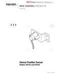
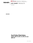
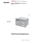
®
MEX (55) 53 63 23 31
DIST. AUTORIZADO QRO (442) 1 95 72 60
MTY (81) 83 54 10 18
[email protected]
AIR CHAMP PRODUCTS
User Manual
Models FWB, LWB, MWB and HWB
Brakes
(i)
FORM NO. L-20010-F-0301
®
MEX (55) 53 63 23 31
DIST. AUTORIZADO QRO (442) 1 95 72 60
MTY (81) 83 54 10 18
[email protected]
In accordance with Nexen’s established policy of constant product improvement, the specifications contained in this
manual are subject to change without notice. Technical data listed in this manual are based on the latest information
available at the time of printing and are also subject to change without notice.
Technical Support:
800-843-7445
(651) 484-5900
www.nexengroup.com
WARNING
Read this manual carefully before installation and operation.
Follow Nexen's instructions and integrate this unit into your system with care.
This unit should be installed, operated and maintained by qualified personnel ONLY.
Improper installation can damage your system or cause injury or death.
Comply with all applicable codes.
Nexen Group, Inc.
560 Oak Grove Parkway
Vadnais Heights, Minnesota 55127
Copyright 2000 Nexen Group, Inc.
ISO 9001 Certified
(ii)
®
MEX (55) 53 63 23 31
DIST. AUTORIZADO QRO (442) 1 95 72 60
MTY (81) 83 54 10 18
[email protected]
Table of Contents
Introduction ---------------------------------------------------------------------------------------------------------------------------------------- 1
Installation ---------------------------------------------------------------------------------------------------------------------------------------- 1
Brake Guard Installation --------------------------------------------------------------------------------------------------------------------- 1
Lubrication ----------------------------------------------------------------------------------------------------------------------------------------- 2
Parts Replacement ----------------------------------------------------------------------------------------------------------------------------- 2
Replacement Parts ----------------------------------------------------------------------------------------------------------------------------- 3
Accessories --------------------------------------------------------------------------------------------------------------------------------------- 3
Parts List ------------------------------------------------------------------------------------------------------------------------------------------- 4
Warranties ----------------------------------------------------------------------------------------------------------------------------------------- 5
(iii)
®
MEX (55) 53 63 23 31
DIST. AUTORIZADO QRO (442) 1 95 72 60
MTY (81) 83 54 10 18
[email protected]
INTRODUCTION
Read this manual carefully, making full use of its explanations and instructions. The “Know How” of safe, continuous,
trouble-free operation depends on the degree of your understanding of the system and your willingness to keep all
components in proper operating condition. Pay particular attention to all NOTES, CAUTIONS, and WARNINGS to avoid
the risk of personal injury or property damage. It is important to understand that these NOTES, CAUTIONS, and
WARNINGS are not exhaustive. Nexen cannot possibly know or evaluate all conceivable methods in which service may
be performed, or the possible hazardous consequences of each method. Accordingly, anyone who uses a procedure
that is not recommended by Nexen must first satisfy themselves that neither their safety nor the safety of the product
will be jeopardized by the service method selected.
INSTALLATION
16
1
Machine
Shaft
This unit has rotating parts. Nexen recommends installing a guard if the unit is used in
an area where injury to an operator could
occur. Contact your local Nexen Distributor
for information regarding guards specifically
designed for use with ''Air Champ'' brakes.
Torque
Pin
NOTE: The brake may be secured to the machine
surface by using either the four holes in the Air
Chamber (Item 8) and bolting the brake to the
machine housing or by using a torque pin
through the slot in the bottom of the Air
Chamber (See Figure 1).
1
1
Air
Chamber
(Item 8)
FIGURE 1
1. Insert the Key (Item 16) into the machine shaft and,
slide the brake over the machine shaft and Key (See
Figure 1).
2. Install and tighten the three Set Screws (Item 1) to
secure the brake to the machine shaft (See Figure 1).
BRAKE GUARD INSTALLATION
1. Align the mounting holes of the Brake Guard with the
four tapped holes in the Air Chamber or the brake
(See Figure 2).
Brake
Guard
2. Using the four 10-24 X 3/8 Phillips Head Pan
Screws and Internal Tooth Lock Washers, secure the
Brake Guard to the brake.
Air
Chamber
FIGURE 2
BRAKE GUARD INSTALLATION
FORM NO. L-20010-F-0301
1
®
MEX (55) 53 63 23 31
DIST. AUTORIZADO QRO (442) 1 95 72 60
MTY (81) 83 54 10 18
[email protected]
LUBRICATION
NOTE: Pneumatically actuated devices require clean, pressure regulated, and lubricated air for maximum
performance and long life. The most effective and economical way to lubricate Nexen Brakes is with an Air
Line Lubricator, which injects oil into the pressurized air, forcing an oil mist into the air chamber.
Locate the lubricator above and within ten feet of the Brake, and use a low viscosity oil such as SAE-10.
Synthetic lubricants are not recommended.
LUBRICATOR DRIP RATE SETTINGS
NOTE: These settings are for Nexen supplied lubricators. If you are not using a Nexen lubricator, calibration must
replicate the following procedure.
1. Close and disconnect the air line from the unit.
5. Connect the air line to the unit.
2. Turn the Lubricator Adjustment Knob
counterclockwise three complete turns.
6. Turn the Lubricator Adjustment Knob clockwise until
closed.
3. Open the air line.
7. Turn the Lubricator Adjustment Knob
counterclockwise one-third turn.
4. Close the air line to the unit when a drop of oil forms
in the Lubricator Sight Gage.
8. Open the air line to the unit.
PARTS REPLACEMENT
2
FIGURE 3
6
10
3
7
5
11
9
8
14
13
12
4
Facing (See Figure 3).
NOTE: The, LWB, MWB, and HWB have six
Shoulder Bolts (Item 6), Compression
Springs (Item 7), and O-ring Seals (Item
10). The FWB has three Shoulder Bolts
(Item 6), Compression Springs (Item 7), and
O-ring Seals (Item 10).
Special attention should be exercised when
working with retaining rings or spring loaded
fasteners. Always wear safety goggles when
working with spring or tension loaded
fasteners or devices.
1. Remove the Retaining Ring (Item 13) and press the
Hub Assembly (Item 2) out of the Ball Bearing (Item
14) and Air Chamber (Item 8) (See Figure 3).
4. Remove the old Shoulder Bolts (Item 6), O-ring
Seals (Item 10), and Compression Springs (Item 7)
from the Piston (Item 5) (See Figure 3).
2. Remove the Retaining Ring (Item 12) from the Air
Chamber (Item 8); then, press the old Ball Bearing
(Item 14) out of the Air Chamber (See Figure 3).
5. Slide the Piston (Item 5) out of the Air Chamber
(Item 8) and remove the O-ring Seals (Item 9 and 11)
from the Piston and Air Chamber (See Figure 3).
3. Remove the six old Flat Head Machine Screws
(Item 3) securing the old Friction Facing (Item 4)
to the Piston (Item 5); then, remove the Friction
6. Clean the bearing bore of the Air Chamber (Item 8)
with fresh solvent, making sure all old Loctite®
2
FORM NO. L-20010-F-0301
®
MEX (55) 53 63 23 31
DIST. AUTORIZADO QRO (442) 1 95 72 60
MTY (81) 83 54 10 18
[email protected]
7. Apply an adequate amount of Loctite® 680 to evenly
coat the outer race of the new Ball Bearing (Item 14)
and press the new Ball Bearing into the Air Chamber
(Item 8) (See Figure 3).
13. Install the new Shoulder Bolts (Item 6), Compression
Springs (Item 7), and O-ring Seals (Item 10) through
the Piston (Item 5) and into the Air Chamber (Item 8)
(See Figure 3).
8. Reinstall the Retaining Ring (Item 12) (See Figure 3).
14. Alternately and evenly tighten the new Shoulder Bolts
(Item 6) to 66 In. Lbs. [7.45 N•m] torque (See Figure 3).
9. Apply a thin film of o-ring lubricant to the new O-ring
Seals (Items 9, 10, and 11) and the o-ring contact
surfaces of the Piston (Item 5), Air Chamber (Item
8), and new Shoulder Bolts (Item 6) (See Figure 3).
15. Using six new Flat Head Machine Screws (Item 3),
secure the new Friction Facing (Item 4) to the Piston
(Item 5) (See Figure 3).
10. Install the new O-ring Seals (Items 9, 10, and 11)
(See Figure 3).
16. Tighten the six Flat Head Machine Screws (Item 3) to
22 In. Lbs. [2.50 N•m] torque.
11. Slide the Piston into the Air Chamber, aligning the
holes in the Piston with the holes in the Air Chamber
(See Figure 3).
17. While supporting the inner race of the new Ball
Bearing (Item 14), press the Hub Assembly (Item 2)
into the new Ball Bearing and Air Chamber (Item 8)
(See Figure 3).
12. Slide a new Compression Spring (Item 7) onto each
new Shoulder Bolt (Item 6) (See Figure 3).
18. Reinstall the Retaining Ring (Item 13) (See Figure 3).
REPLACEMENT PARTS
The item or balloon number for all Nexen products is used for part identification on all product parts lists, product price
lists, unit assembly drawings, bills of materials, and instruction manuals.
When ordering replacement parts, specify model designation, item number, part description, and quantity. Purchase
replacement parts through your local Nexen Distributor.
ACCESSORIES
MODEL
TORQUE PI N
BRACKET
PRODUCT NO.
BRAKE GUARD
PRODUCT NO.
FWB
819900
817700
LWB
821400
818300
MWB
823400
826300
HWB
825500
828200
FORM NO. L-20010-F-0301
FIGURE 4
TORQUE PIN BRACKET
3
FIGURE 5
BRAKE GUARD
®
MEX (55) 53 63 23 31
DIST. AUTORIZADO QRO (442) 1 95 72 60
MTY (81) 83 54 10 18
[email protected]
PARTS LIST
16
2
1
6
10
3
7
11
5
9
8
14
13
12
4
FIGURE 6
ITEM
1
2
31
41
5
61
71
8
DESCRIPTION
QTY
Set Screw
Hub Assembly
Flat Head Machine Screw
Friction Facing
Piston
Shoulder Bolt
Compression Spring
Air Chamber
3
1
6
1
1
*
*
1
ITEM
91
101
111
12
13
141
162
DESCRIPTION
QTY
O-ring Seal
O-ring Seal
O-ring Seal
Retaining Ring
Retaining Ring
Ball Bearing
Key
1
*
1
1
1
1
1
1
Denotes Repair Kit item.
When ordering Bushing (Item 15), state the Model Number and required bore size.
* QTY. 3 on FWB and QTY. 6 on LWB, MWB, and HWB
2
REPAI R KITS
MODEL
PRODUCT NO.
FWB
847300
LWB
847400
MWB
847500
HWB
847600
4
FORM NO. L-20010-F-0301
®
MEX (55) 53 63 23 31
DIST. AUTORIZADO QRO (442) 1 95 72 60
MTY (81) 83 54 10 18
[email protected]
WARRANTIES
Warranties
Nexen warrants that the Products will be free from any defects in material or workmanship for a period of 12 months
from the date of shipment. NEXEN MAKES NO OTHER WARRANTY, EXPRESS OR IMPLIED, AND ALL IMPLIED
WARRANTIES, INCLUDING WITHOUT LIMITATION, IMPLIED WARRANTIES OF MERCHANTABILITY AND
FITNESS FOR A PARTICULAR PURPOSE ARE HEREBY DISCLAIMED. This warranty applies only if (a) the Product
has been installed, used and maintained in accordance with any applicable Nexen installation or maintenance manual
for the Product; (b) the alleged defect is not attributable to normal wear and tear; (c) the Product has not been altered,
misused or used for purposes other than those for which it was intended; and (d) Buyer has given written notice of the
alleged defect to Nexen, and delivered the allegedly defective Product to Nexen, within one year of the date of
shipment.
Exclusive Remedy
The exclusive remedy of the Buyer for any breach of the warranties set out above will be, at the sole discretion of Nexen,
a repair or replacement with new, serviceably used or reconditioned Product, or issuance of credit in the amount of the
purchase price paid to Nexen by the Buyer for the Products.
Limitation of Nexen’s Liability
TO THE EXTENT PERMITTED BY LAW NEXEN SHALL HAVE NO LIABILITY TO BUYER OR ANY OTHER PERSON
FOR INCIDENTAL DAMAGES, SPECIAL DAMAGES, CONSEQUENTIAL DAMAGES OR OTHER DAMAGES OF
ANY KIND OR NATURE WHATSOEVER, WHETHER ARISING OUT OF BREACH OF WARRANTY OR OTHER
BREACH OF CONTRACT, NEGLIGENCE OR OTHER TORT, OR OTHERWISE, EVEN IF NEXEN SHALL HAVE
BEEN ADVISED OF THE POSSIBILITY OR LIKELIHOOD OF SUCH POTENTIAL LOSS OR DAMAGE. For all of
the purposes hereof, the term “consequential damages” shall include lost profits, penalties, delay images, liquidated
damages or other damages and liabilities which Buyer shall be obligated to pay or which Buyer may incur based upon,
related to or arising out of its contracts with its customers or other third parties. In no event shall Nexen be liable for
any amount of damages in excess of amounts paid by Buyer for Products or services as to which a breach of contract
has been determined to exist. The parties expressly agree that the price for the Products and the services was
determined in consideration of the limitation on damages set forth herein and such limitation has been specifically
bargained for and constitutes an agreed allocation of risk which shall survive the determination of any court of
competent jurisdiction that any remedy herein fails of its essential purpose.
Limitation of Damages
In no event shall Nexen be liable for any consequential, indirect, incidental, or special damages of any nature whatsoever, including without limitation, lost profits arising from the sale or use of the Products.
Warranty Claim Procedures
To make a claim under this warranty, the claimant must give written notice of the alleged defect to whom the Product
was purchased from and deliver the Product to same within one year of the date on which the alleged defect first
became apparent.
Nexen Group, Inc.
560 Oak Grove Parkway
Vadnais Heights, MN 55127
800.843.7445
Fax: 651.286.1099
www.nexengroup.com
ISO 9001 Certified
FORM NO. L-20010-F-0301
5