1
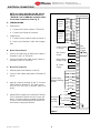
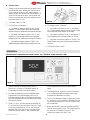
®
MEX (55) 53 63 23 31
DIST. AUTORIZADO QRO (442) 1 95 72 60
MTY (81) 83 54 10 18
[email protected]
WEB CONTROL PRODUCTS
User Manual
Tension Meter
TM140-D
1
FORM NO. L-20186-B-0702
®
MEX (55) 53 63 23 31
DIST. AUTORIZADO QRO (442) 1 95 72 60
MTY (81) 83 54 10 18
[email protected]
In accordance with Nexen’s established policy of constant product improvement, the specifications contained in this
manual are subject to change without notice. Technical data listed in this manual are based on the latest information
available at the time of printing and are also subject to change without notice.
Technical Support: 800-843-7445
(651) 484-5900
www.nexengroup.com
DANGER
Read this manual carefully before installation and operation.
Follow Nexen's instructions and integrate this unit into your system with care.
This unit should be installed, operated and maintained by qualified personnel ONLY.
Improper installation can damage your system or cause injury or death.
Comply with all applicable codes.
Nexen Group, Inc.
560 Oak Grove Parkway
Vadnais Heights, Minnesota 55127
ISO 9001 Certified
Copyright 1999 Nexen Group, Inc.
FORM NO. L-20186-B-0702
2
®
MEX (55) 53 63 23 31
DIST. AUTORIZADO QRO (442) 1 95 72 60
MTY (81) 83 54 10 18
[email protected]
TABLE OF CONTENTS
Introduction --------------------------------------------------------------------------------------------------------------------------- 4
Installation ----------------------------------------------------------------------------------------------------------------------------- 5
Electrical Connections ------------------------------------------------------------------------------------------------------------ 6
Adjustment of Full Scale Value ------------------------------------------------------------------------------------------------- 7
Sensor Calibration ----------------------------------------------------------------------------------------------------------------- 7
Operation ------------------------------------------------------------------------------------------------------------------------------ 8
Maintenance -------------------------------------------------------------------------------------------------------------------------- 9
Fuse Replacement ----------------------------------------------------------------------------------------------------------------- 9
Check Terminal Values ------------------------------------------------------------------------------------------------------------ 9
Troubleshooting ------------------------------------------------------------------------------------------------------------------- 10
Mounting Dimensions ----------------------------------------------------------------------------------------------------------- 12
Specifications ---------------------------------------------------------------------------------------------------------------------- 13
Warranty ----------------------------------------------------------------------------------------------------------------------------- 14
3
FORM NO. L-20186-B-0702
®
MEX (55) 53 63 23 31
DIST. AUTORIZADO QRO (442) 1 95 72 60
MTY (81) 83 54 10 18
[email protected]
INTRODUCTION
Nexen’s “TM140D” Tension Meter measures, displays,
and provides proportional output signals, based upon
tension generated in a continuous strip process.
“TM140D” provides the excitation for two LDVT based
MB Series tension sensing load cells. The load cells
measure web tension and provide a low voltage output
signal proportional to that tension.
The “TM140D” amplifies the signals from the two load
cells separately (See Fig. 1) and feeds the Digital
Display and several output circuits with the resultant
amplified signals. The Read Out Selector Switch
determines which of the buffered signals will be
displayed on the Digital Display and at the Recorder
Terminals.
These buffered signals are also present at Terminals
26, 27, and 28 located on the back panel of the
“TM140D.” These three terminals are not affected by
position of the Read Out Selector Switch. The total
tension signal is also presented as a 4 to 20 mA signal
at Terminals 10 and 11 and as a 0 to 10 VDC signal at
Terminals 29 and 30. These two signals are not
buffered or filtered.
A Zero Tension Circuit is also provided. The Zero
Tension Circuit closes a Normally Open (N.O.) relay
when tension drops to a low level, as would occur
during a web break. This circuit is controlled with a
front panel switch and may be disabled when running at
extremely low tensions to prevent nuisance tripping.
Read this manual carefully, making full use of its
explanations and instructions. The “Know How” of safe,
continuous, trouble-free operation depends on the
degree of your understanding of the system and your
willingness to keep all components in proper operating
condition. Pay particular attention to all NOTES,
CAUTIONS, and WARNINGS to avoid the risk of
personal injury or property damage. It is important to
understand that these NOTES, CAUTIONS, and
WARNINGS are not exhaustive. Nexen can not
possibly know or evaluate all conceivable methods in
which service may be performed, or of the possible
hazardous consequences of each method. Accordingly,
anyone who uses a procedure which is not
recommended by Nexen must first satisfy themselves
that neither their safety or the safety of the product will
be jeopardized by the service method selected.
No. 1
No. 2
Total
MB #1
No. 1 Amp.
Read Out
Selector Switch
Buffer
Tension
Indicator
Buffer
No. 2 Amp.
MB #2
+
Terminal Block
Connections on
Back Panel
Recorder
Terminals
Buffer
Amp
0-10 VDC
Amp
4-20 mA
Figure 1
FORM NO. L-20186-B-0702
4
®
MEX (55) 53 63 23 31
DIST. AUTORIZADO QRO (442) 1 95 72 60
MTY (81) 83 54 10 18
[email protected]
INSTALLATION
NOTE: “TM140D” is an electronic component
and should be mounted in a dry, dust-free,
shock and vibration-free area which has an
ambient temperature of more than 32º F [0º
C] and less than 122º F [50º C].
A. SHELF OR WALL MOUNTING
1. Remove two screws located in TM140D front panel
(See Fig. 2).
Figure 2
2. Remove TM140D from mounting shell (See Fig. 2).
3. Install Mounting Brackets
a. For Shelf Mounting use the two mounting
brackets and four wing screws provided (See Fig. 3).
NOTE: Brackets may also be mounted to the
upper screw holes to allow under shelf
mounting.
b. For Wall Mounting, secure two mounting brackets
with the four wing screws provided (See Fig. 4)
Figure 3
4. After mounting brackets have been installed,
secure mounting shell to shelf or wall using
customer provided screws.
5. Reinsert TM140D into mounting shell and secure
with two screws removed in Step 1 (See Fig. 2).
B. PANEL MOUNTING
Figure 4
1. Insert “TM140D” into cutout in panel (See Fig. 5
for Panel Cutout Dimensions).
2. Insert Slides into grooves of TM140D mounting
shell.
Panel Cut Out
3. Using four Wing Screws provided, secure Mounting
Brackets to Mounting Shell (See Fig. 6).
4. Insert Adjustment Screws and Jam Nuts into center
hole of Mounting Brackets (See Fig. 6).
93 mm
3.66 in
189 mm
7.44 in
Figure 5
5. Adjust screws until panel is firmly clamped between
“TM140” Front Panel Bezel and Slides (See Fig.
6).
6. Tighten Jam Nut.
Figure 6
5
FORM NO. L-20186-B-0702
®
MEX (55) 53 63 23 31
DIST. AUTORIZADO QRO (442) 1 95 72 60
MTY (81) 83 54 10 18
[email protected]
ELECTRICAL CONNECTIONS
NOTE: Use cables provided with MB Tension
Sensor to connect MB Tension Sensors to
“TM140-D.” Use 18 AWG two connector cable
for all other connections (See Fig. 7).
External Terminals
Green
Tension
Sensor
No. 1
A. SENSOR WIRING.
1. Dual Sensors.
a.
Connect both Sensor Cables to “TM140-D.”
b.
Connect both Shields to Terminal 9.
Red
Black
Green
Yellow
Tension
Sensor
No. 2
2. Single Sensor.
a.
Yellow
Connect Sensor Cable as shown for Sensor 1.
Red
Black
b. Short across Terminals 5 and 6 with a jumper
wire.
White
+
Control Output
4 - 20 mA
B. REVERSE TENSION SENSING
1. Connect YELLOW wires of MB Sensor Cables to
Terminals 1 and 5 of “TM140-D.”
Zero Tension
Output
2. Connect GREEN wires of MB Sensor Cables to
Terminals 2 and 6 of “TM140-D.”
External Meter
Output (1 mA)
C. REMOTE TENSION INDICATOR
AC Power
Supply
+
1. Remove jumper from Terminals 14 and 15.
100V
2. Connect 1 mA remote meter leads to Terminals 14
and 15.
D. Apply AC power to Terminals 16 and 17. Connect
Earth Ground to Terminal 25. AC power can be
100-110, 120, 200, 220, or 240 VAC either 50 or
60 Hz.
110V
Power Supply
Voltage Selecting
Wiring
120V
200V
220V
240V
Earth
E. Voltage Select Jumper wire connected to Terminal
18 is connected to Terminal 24 (240 V) from the
factory. If another voltage is applied at Terminals
16 and 17, then remove jumper from Terminal 24
and connect to the proper terminal.
Measuring
Outpput
0 to 10V
No. 1 Tension
+
No. 2 Tension
+
Total Tension
+
COM
Control Output 0 tp 10V
Figure 7
FORM NO. L-20186-B-0702
6
+
1
2
3
4
5
6
7
8
9
10 Zero
11 Tension
Contact
12
13
14
15
16
17
18
19
20
21
22
23
24
25
26
27
28
29
30
®
MEX (55) 53 63 23 31
DIST. AUTORIZADO QRO (442) 1 95 72 60
MTY (81) 83 54 10 18
[email protected]
ADJUSTMENT OF FULL SCALE VALUE
1. Slide Adjustment Window to the left to open (See
Fig. 8).
2. Set Power Switch to “ON”.
3. Set “SW1-1” to “OFF” and “SW1-2” to “ON” (See
Table 1).
4. Set SW1-3 and SW1-4 according to Table 1.
8. Rotate VR2 until Indicator reads maximum desired
tension readout value. This value can be anywhere
between “0” and “1999”.
9. Set SW1-1 to “ON” and SW1-2 to “OFF”.
10. Close Adjustment Window.
11. Set Power Switch to “OFF”.
FULL SCALE VALUE DIGITAL READ OUT SW1-3 SW1-4
100 - 1999 lb
0000
10.0 - 99.99 lb
000.0
5.00 - 9.99 lb
00.00
OFF
ON
OFF
OFF
OFF
ON
5. Rotate VR1 to MIN (Fully Counterclockwise) (See
Fig. 8).
6. Rotate VR3 to obtain “000” on the Display.
7.
Rotate VR1 to MAX (Fully Clockwise) (See Fig. 8).
Figure 8
SENSOR CALIBRATION
Figure 9
A. ZERO ADJUSTMENT
NOTE: Perform Zero Adjustment with no web
on sensing roll and no other objects sitting
or leaning on roll or sensors.
4. Set Read Out Selector Switch “No. 2” and adjust
No. 2 Zero Variable Resistor until Digital Display
displays “ZERO”.
NOTE: When using only one sensor, make
sure that a jumper wire is provided between
Terminals 5 and 6.
1. Set Power Switch to “ON”.
2. Set Zero Tension Switch to “OFF”.
5. Set Read Out Selector Switch to “TOTAL”. The
Digital Display must still show “ZERO.”
3. Set Read Out Selector Switch to “No. 1” and
adjust No.1 Zero Variable Resistor until Digital
Display displays “ZERO”.
6. Set Zero Tension Switch to “ON”.
7.
7
Set Power Switch to “OFF”.
FORM NO. L-20186-B-0702
®
MEX (55) 53 63 23 31
DIST. AUTORIZADO QRO (442) 1 95 72 60
MTY (81) 83 54 10 18
[email protected]
B. SPAN ADJUSTMENT
1. Thread a rope or narrow web over the sensor roll in
the normal web path, making sure that the rope is
in the center of the sensor roll. Hang a known
weight (weight must be less than the Maximum Full
Scale) on one end of the rope. Secure other end
of rope to machine with the known weight held off
the ground (See Fig. 10).
2. Set Power Switch to “ON”.
3. For Two Sensor Calibration:
Figure 10
4. For Single Sensor Calibration:
a. Set Read out Selector Switch to “No. 1”, and
adjust No. 1 Span variable resistor until the Digital
Display shows one half the known weight on the rope.
a. Set Read Out Selector to “No. 1” and adjust
No. 1 Span variable resistor until the Digital Display
shows the total known weight on the rope.
b. Set Read Out Selector Switch to “No. 2”, and
adjust No. 2 Span variable resistor until the Digital
Display shows one half the known weight on the rope.
b. Set Read Out Selector to “No. 2” and turn No. 2
Span variable resistor counterclockwise to “ZERO”.
c. Set Read Out Selector Switch to “TOTAL”. The
Digital Display must read the total known weight on
the rope.
c. Set Read Out Selector Switch to “TOTAL”. The
Digital Display must read the known weight on the rope.
5. Set Power Switch to “OFF”.
OPERATION
Start machine in operation with a web in place. Set “TM140-D” Power Switch to “ON”.
Figure 11
1. Tension Indicator will display tension at No. 1
Sensor, No. 2 Sensor, or Total Web Tension, as
commanded by Read Out Selector Switch.
2. Recorder Terminals will put out a buffered signal,
proportional to the Digital Display, with 0 to 10
volts being equal to zero to full scale in high-range.
Recorder Terminals are also controlled by the Read
Out Selector Switch.
3. The No. 1, No. 2, and Total signals at terminals 26,
27, 28, and 29 on the back panel (See Fig. 7, Page
3) are also proportional at 0 to 10 volts equal to
Maximum Full Scale, but are not controlled by the
Read Out Selector Switch. They constantly put
FORM NO. L-20186-B-0702
out the appropriate proportional and buffered
signal.
4. The External Meter Terminals 14 and 15 present a
0 to 1 milliampere buffered output which is also
proportional to Maximum Full Scale.
5. The 4 to 20 milliampere signal at Terminals 10 and
11, and the 0 to 10 volt signal at Terminals 29 and
30 are also proportional to 0 to Full Scale but they
are not buffered.
6. When tension falls to zero, the normally open Zero
Tension Relay contacts close. This relay signal can
be picked up at Terminals 12 and 13. The
contacts are rated at 250 VAC, 0.2A.
8
®
MEX (55) 53 63 23 31
DIST. AUTORIZADO QRO (442) 1 95 72 60
MTY (81) 83 54 10 18
[email protected]
MAINTENANCE
Nexen’s “TM140-D” does not require maintenance. Periodically check that the pillow block bearings mounted to the
Tension Sensors have not moved. Nexen also recommends checking Zero and Span Adjustment (See Sensor
Calibration) if close accuracy is required.
FUSE REPLACEMENT
“TM140-D” has two protective fuses. One fuse is in the incoming AC line; the other fuse protects the Zero Tension
circuit from the feedback voltage resulting from damage to the device connected to the Zero Tension Terminals.
AC Line Fuse
1. The AC Line Fuse is rated 0.2A Slow Blow. It is
located on the back panel by the Terminal block.
Lift the catch below the fuse holder to remove the
fuse holder.
2. Replace the fuse with the Slow Blow 0.2 amp
spare fuse provided.
3. Reinstall the fuse holder, making sure it clicks into
place when the catch holds.
Zero Tension Fuse
1. The Zero Tension Fuse is located on the Main
Printed Circuit Board. It is rated at 0.2A Instant
Blow. To replace the Zero Tension Fuse, remove
the two screws from the front panel of the “TM140D” and remove the “TM140-D” from the Mounting
Shell (See Sect. III, Para. A, Steps 1 and 2).
2. Remove the defective fuse from the fuse holder and
replace with the 0.2 amp Instant Blow fuse provided.
Figure 12
3. Install the “TM140-D” into the Mounting Shell and
re-secure the two screws.
CHECK TERMINAL VALUES
Refer to Figure 13.
Remove two screws from “TM140-D” front panel and
slide “TM140-D” out of the Mounting Shell (See Sect.
II, Para. A, Steps 1 and 2). This will expose the
CHECK TERMINAL and COMMON PIN. The
COMMON PIN is used for checking all voltages
except the power supply for the Tension Sensor. When
checking the Tension Sensor Power Supply circuit,
check Terminal 6 is used as COMMON.
Power Supply
Signal Line
CHECK
CP5
CP6
CP7
CP8
CP1
CP2
CP3
CP4
Figure 13
CHECK ITEMS
Power Supply for Sensor Reference Point
NORMAL CONDITION
About +6 VDC
Power Supply for Operational Amplifier
Power Supply for Operational Amplifier
Tension at No. 1 Sensor
Tension at No. 2 Sensor
Total Tension
Tension Value on the Digital Display
About +15 VDC
About +15VDC
Value corresponding to
tension with Zero to Full
Scale equals 0-10 V
Same as CP3
9
FORM NO. L-20186-B-0702
®
MEX (55) 53 63 23 31
DIST. AUTORIZADO QRO (442) 1 95 72 60
MTY (81) 83 54 10 18
[email protected]
TROUBLESHOOTING
START
Are the DC power supply NO
voltages normal?
• Check voltages using the check
terminal for the power supply.
YES
Is tension normally indicated
NO
when a load is applied/released
• Does the indication on the Digital
to/from the sensor roll?
Display return to zero when the
YES
load is removed?
• Does the indication reading
change as the Seadout Selector
switch is cycled?
Are each of the external
output terminal
readings normal?
NO
Go to “A” power supply
circuit check.
Go to “B” tension
sensor check.
The main board
is defective.
YES
No Fault
“A” power supply circuit check
Is the Voltage Selector Jumper
set to the AC power supply
voltage used?
YES
NO
Set it to the power supply
voltage being used.
Is the AC power supply voltage NO
within the tolerance (± 10%)?
Adjust the voltage within the
tolerance.
YES
Is the power fuse blown?
YES
Replace it with the specified
fuse (0.2A Slow Blow).
NO
The power supply circuit
board is defective.
FORM NO. L-20186-B-0702
10
®
MEX (55) 53 63 23 31
DIST. AUTORIZADO QRO (442) 1 95 72 60
MTY (81) 83 54 10 18
[email protected]
“B” power supply circuit check
Is a voltage proportional to
tension generated at check
terminal CP4?
NO
YES
Is the connector for Digital
Display connected to the
specified terminal?
NO
Connect to the specified
connector.
YES
• AX1 is defective.
• External terminal 14 and 15
are not short-circuited. Or
external indicator (1mA ameter)
is not connected.
Is the AC power supply voltage NO
within the tolerance (± 10%)?
Is the sum of CP1 and CP2
generated at CP3?
NO
NO
HIC is defective.
YES
Can Zero adjustment be made?
• RANGE Switch is defective.
• HIC is defective.
NO
YES
Is Sensor’s load plate in
contact with limiting stops?
YES
NO
Are the voltages between
external terminals 2 and 29 and
NO
between 6 and 29 changed
when turning No. 1 and No.2
Zero Adjustment VR’s?
Are the voltage changes between 1 and 29 and between 5
and 29 the same as above?
NO
• Unsuitable pillow block mounting.
• Sensor roll weight too high.
• Sensor is defective.
Zero Adjustment circuit is defective.
Incorrect external wiring, or
sensor is defective.
YES
HIC is defective.
Can Span adjustment be made?
YES
Does the Digital Display return
to zero when tension is
reduced to zero?
YES
NO
Is a voltage proportional to the
YES
tension value generated between external terminal 1 and 2
or 5 and 6?
YES
• Working force is small compared
to sensor’s load range.
• Unsuitable wrap angle.
• Sensor is defective.
• Span is outside of specified
range.
• HIC is defective.
NO
Is the connector for Digital
Display connected to the
specified terminal?
YES
NO
• Do not apply excessive force to
sensor, otherwise hysteresis will
occur.
Sensor is defective.
No fault in the Tension sensor.
11
FORM NO. L-20186-B-0702
®
MEX (55) 53 63 23 31
DIST. AUTORIZADO QRO (442) 1 95 72 60
MOUNTING DIMENSIONS
Figure 14
FORM NO. L-20186-B-0702
12
MTY (81) 83 54 10 18
[email protected]
®
MEX (55) 53 63 23 31
DIST. AUTORIZADO QRO (442) 1 95 72 60
MTY (81) 83 54 10 18
[email protected]
SPECIFICATIONS
Rated Torque ------------------------------------------------------------------------ 5, 10, 20, 50, 100, 200,300, 500, 1000 lbs or kg
Power Supply ---------------------------------------------------------------------- 100, 110, 120, 200, 220, and 240 VAC, 50/60 Hz
Ambient Temperature ---------------------------------------------------------------------------------------------- 32° to 122°F [0° to 50° C]
Weight ----------------------------------------------------------------------------------------------------------------------------------- 3.3 lbs [1.5 kg]
OUTPUT
TERMINAL NUMBER
TOTAL: 0-10 VDC (2 mA)
28--29
Number 1: 0-10 VDC (2 mA)
26--29
Number 2: 0-10 VDC (2 mA)
27--29
0-10 VDC (2 mA)
Front Panel
TOTAL: 0-10 VDC (2 mA)
30--29
TOTAL: 4-20 mA DC (500 Ohm Load)
10--11
OUTPUT for EXTERNAL INDICATOR
0-1 mA DC
14--15
ZERO TENSION CONTACT
Rated 250 VAC, 30 VAC, 0.2 A
12--13
MEASUREMENT OUTPUT
CONTROL OUTPUT
13
FORM NO. L-20186-B-0702
®
MEX (55) 53 63 23 31
DIST. AUTORIZADO QRO (442) 1 95 72 60
MTY (81) 83 54 10 18
[email protected]
WARRANTY
Warranties
Nexen warrants that the Products will be free from any defects in material or workmanship for a period of 12 months
from the date of shipment. NEXEN MAKES NO OTHER WARRANTY, EXPRESS OR IMPLIED, AND ALL IMPLIED
WARRANTIES, INCLUDING WITHOUT LIMITATION, IMPLIED WARRANTIES OF MERCHANTABILITY AND FITNESS FOR A PARTICULAR PURPOSE ARE HEREBY DISCLAIMED. This warranty applies only if (a) the
Product has been installed, used and maintained in accordance with any applicable Nexen installation or maintenance
manual for the Product; (b) the alleged defect is not attributable to normal wear and tear; (c) the Product has not been
altered, misused or used for purposes other than those for which it was intended; and (d) Buyer has given written
notice of the alleged defect to Nexen, and delivered the allegedly defective Product to Nexen, within one year of the
date of shipment.
Exclusive Remedy
The exclusive remedy of the Buyer for any breach of the warranties set out above will be, at the sole discretion of
Nexen, a repair or replacement with new, serviceably used or reconditioned Product, or issuance of credit in the
amount of the purchase price paid to Nexen by the Buyer for the Products.
Limitation of Nexen’s Liability
TO THE EXTENT PERMITTED BY LAW NEXEN SHALL HAVE NO LIABILITY TO BUYER OR ANY OTHER PERSON
FOR INCIDENTAL DAMAGES, SPECIAL DAMAGES, CONSEQUENTIAL DAMAGES OR OTHER DAMAGES OF
ANY KIND OR NATURE WHATSOEVER, WHETHER ARISING OUT OF BREACH OF WARRANTY OR OTHER
BREACH OF CONTRACT, NEGLIGENCE OR OTHER TORT, OR OTHERWISE, EVEN IF NEXEN SHALL HAVE
BEEN ADVISED OF THE POSSIBILITY OR LIKELIHOOD OF SUCH POTENTIAL LOSS OR DAMAGE. For all of
the purposes hereof, the term “consequential damages” shall include lost profits, penalties, delay images, liquidated
damages or other damages and liabilities which Buyer shall be obligated to pay or which Buyer may incur based
upon, related to or arising out of its contracts with its customers or other third parties. In no event shall Nexen be liable
for any amount of damages in excess of amounts paid by Buyer for Products or services as to which a breach of
contract has been determined to exist. The parties expressly agree that the price for the Products and the services was
determined in consideration of the limitation on damages set forth herein and such limitation has been specifically
bargained for and constitutes an agreed allocation of risk which shall survive the determination of any court of competent jurisdiction that any remedy herein fails of its essential purpose.
Limitation of Damages
In no event shall Nexen be liable for any consequential, indirect, incidental, or special damages of any nature whatsoever, including without limitation, lost profits arising from the sale or use of the Products.
Warranty Claim Procedures
To make a claim under this warranty, the claimant must give written notice of the alleged defect to whom the Product
was purchased from and deliver the Product to same within one year of the date on which the alleged defect first
became apparent.
Nexen Group, Inc.
560 Oak Grove Parkway
Vadnais Heights, MN 55127
800.843.7445
Fax: 651.286.1099
www.nexengroup.com
ISO 9001 Certified
FORM NO. L-20186-B-0702
14