1
Interface Control Document Between ALMA
Phasing Project and ALMA Computing
ALMA-05.11.00.00-70.35.25.00-A-ICD
2014-10-07
Prepared By:
Organization Role:
R. Lacasse
NRAO
Geoff Crew
Haystack Observatory
M. Honma
NAOJ
Approved By:
Organization Role:
Richard Lacasse
APP SE/Lead Engineer
Nick Whyborn
ALMA Array Lead Engineer
Jorge Ibsen
ICT Manager
Released By:
Organization Role:
Michael Hecht
APP Project Manager
Date and Signature:
Date and Signature:
Date and Signature:
ALMA Project
Interface Control Document
Between ALMA Phasing Project
And ALMA Computing
Doc #: ALMA- 05.11.00.00-70.35.25.00-A-ICD
Date: 2014-10-07
Status: Draft
(Draft, Pending, Approved, Released, Superseded, Obsolete)
Page:
2 of 44
Change Record
Version
Date
A
2013-3-14
Affected
Section(s)
ALL
A01
2013-3-18
Several
None
Incorporate comments by Geoff Crew and Alejandro
Saez
A02
2013-4-1
Several
None
A03
A04
2013-4-15
2013-4-22
Several
File name
None
None
Change ANALOG_SUM_MODE protocol to use a 16msec sync instead of a 1-msec sync for PRN generator.
Add a requirement to the recorder’s interface with
computing that it be able to connect to a server running
the NTP protocol.
Delete GET_VDIF_HEADER protocol
Update GET_PIC_STATUS protocol
Update per comments from Geoff Crew.
Correct doc number in file name.
Update VDIF frame illustration (Fig. 3.6)
A05
2013-5-11
3.1.1
None
Correct reference to RD-01 (was RD-07)
A06
2013-5-13
Fig. 3-1
None
Correct outdated figure
A07
2013-8-9
Doc. #
None
Updated to current document number format
A08
2013-8-19
Several
To Be Done
A09
2013-8-22
A10
2014-2-28
Updated CAN-protocol-related numbers for LTA and
SCC protocols.
Updated protocol description of both SCC commands.
Fix typo on p. 20. PSN is 8 Bytes, not 4 Bytes.
Fix typo in 3.2.2.2.2. Changed
DOWNLOAD_VDIF_STATUS to
DOWNLOAD_VDIF_HEADER, 2 places
Clarify the start-up procedure to show how the
commands must be synchronized to external timing.
This is included in the SET_PIC_CTRL protocol
description.
Change the statistics readout from 2 bytes to 3 bytes
per state.
Add a bit in status word 52 to indicate whether the
ROACH is on or off.
2014-3-4
Change
Request #
None
Reason/Initiation/Remarks
First Issue
ALMA Project
Interface Control Document
Between ALMA Phasing Project
And ALMA Computing
A11
2014-3-19
-
-
A12
2014-4-2
-
-
2014-4-21
-
-
(Draft, Pending, Approved, Released, Superseded, Obsolete)
Page:
3 of 44
Assign StructType to DOWNLOAD_VDIF_HEADER
and SET_PIC_CONTROL
Assign function codes to APPLY_VDIF_HEADER,
Add the time-to-completion of the
DOWNLOAD_VDIF_HEADER and
APPLY_VDIF_HEADER commands.
Changed title page:
prepared by: add Alejandro Saez
released by: replace Mark McKinnon with TBD
Specify zero as the structure type for
DOWNLOAD_VDIF_HEADER.
Specify 20503 as the Message RCA for
GET_DOWNLOAD_VDIF_HEADER_STATUS.
Specify the meaning of the bits in VDIFstatus for
protocol
GET_DOWNLOAD_VDIF_HEADER_STATUS.
Specify three as the function code for the
APPLY_VDIF_HEADER command.
GET_DOWNLOAD_VDIF_HEADER_STATUS:
Change RCA from 205xx to 20503. Specify values for
the return value.
A13
A14
Doc #: ALMA- 05.11.00.00-70.35.25.00-A-ICD
Date: 2014-10-07
Status: Draft
APPLY_VDIF_HEADER: change function code from
x to 3.
GET_APPLY_VDIF_HEADER_STATUS: Change
RCA from 205xx and 20503 to 20504. Add several
possible states to the status
SET_PIC_CTRL: Change Type from X to 1. Clarify
the function of LDR, GRS, TGSD FMS and NVLD
control bits.
GET_PIC_STATUS: Change function code from X to
3 and type from Y to 0.
A15
2014-4-22
-
-
Get_PIC_Status: Delete the “Type” parameter
DOWNLOAD_VDIF_HEADER: Change the number
of bytes in data messages from 36 to 40.
A16
2014-5-4
-
-
GET_DOWNLOAD_VDIF_HEADER_STATUS:
clarify the possible values of the return value.
Add applicable documents AD-06 and AD-07
ALMA Project
Interface Control Document
Between ALMA Phasing Project
And ALMA Computing
Doc #: ALMA- 05.11.00.00-70.35.25.00-A-ICD
Date: 2014-10-07
Status: Draft
(Draft, Pending, Approved, Released, Superseded, Obsolete)
Page:
4 of 44
A17
2014-5-4
-
-
A18
2014-5-6
-
-
A19
2014-5-15
-
-
A20
2014-6-11
-
-
Add a status bit to indicate FPGA write error to the
protocol GET_APPLY_VDIF_HEADER_STATUS.
A21
2014-6-12
-
-
A22
2014-7-17
-
-
A23
2014-8-1
-
-
A24
2014-9-10
-
-
Update Figure 3.6
Change the suggested startup procedure for the PIC
Clarify a typo concerning ROACH_write_error in
GET_APPLY_VDIF_STATUS
Add GrsFm to Control Byte 1
Update GET_PIC_STATUS protocol to show the
availability of the sampled 1-PPS counter.
Modify figure 3-5 to show different binary codes for
data to Station Interface Card and Phasing Interface
Card.
Update DOWNLOAD_VDIF_HEADER protocol to
show details of the status words provided by the PIC in
the VDIF data frames
Incorporate Geoff’s comments to the draft of the
above.
Change the recommended PIC startup procedure (step
4d).
In the CAN protocol GET_PIC_Status, added bits 2, 3
and 4 to PIC status byte 53
In SET_PIC_CONTROL, add bit 2 in control word 1
to enable re-seeding of the PRN test data generator
A25
2014-09-10
Alejandro
Caceres
For the DOWNLOAD_VDIF_HEADER protocol,
change the “Data in Data Messages” from 36 to 40.
Clarify the startup procedure in SET_PIC_CTRL
In the SET_PIC_CONTROL protocol,
• Change the definition of ICH
• Change the definition of SCH
In the GET_PIC_STATUS protocol, add bit 1 to the
ENV0 status byte
Update the DOWNLOAD_VDIF_HEADER protocol
to show what bits are sent by the CCC, and the
requirements for the least significant nibble of the
Magic Word.
Change the meaning of the bits in Word 5 to reflect
current status and future goals.
Regular ICD number assigned
ALMA Project
Interface Control Document
Between ALMA Phasing Project
And ALMA Computing
Doc #: ALMA- 05.11.00.00-70.35.25.00-A-ICD
Date: 2014-10-07
Status: Draft
(Draft, Pending, Approved, Released, Superseded, Obsolete)
Page:
5 of 44
A26
2014-09-29
F.
Sepulveda
Signature matrix modified according to N. Whyborn’s
comments.
A27
2014-10-07
R. Lacasse
Respond to Nick Whyborn’s comments:
• TBDs removed
• Added applicable docs to provide req. info
• Clarified responsibility for recorder interface.
Fix a typo in Table 3
ALMA Project
Interface Control Document
Between ALMA Phasing Project
And ALMA Computing
Doc #: ALMA- 05.11.00.00-70.35.25.00-A-ICD
Date: 2014-10-07
Status: Draft
(Draft, Pending, Approved, Released, Superseded, Obsolete)
Page:
6 of 44
Table of Contents
1 Description .......................................................................................................................8
1.1 Purpose........................................................................................................................8
1.2 Scope ...........................................................................................................................8
2 Applicable Document, Reference Documents, Acronyms and Definitions ................8
2.1 Applicable Documents ................................................................................................8
2.2 Reference Documents .................................................................................................9
2.3 Abbreviations and Acronyms .....................................................................................9
2.4 Definitions.................................................................................................................11
3 Interfaces to Various Subsystems ................................................................................11
3.1 Hydrogen Maser........................................................................................................11
3.1.1 Introduction .......................................................................................................11
3.1.2 Background .......................................................................................................11
3.1.1 H-Maser Interface to Computing ......................................................................13
3.2 64-Antenna Correlator Upgrades ..............................................................................13
3.2.1 Introduction .......................................................................................................14
3.2.2 Interface to Computing .....................................................................................14
3.2.3 Other Interfaces to PIC .....................................................................................41
3.3 Optical Fiber Link System Interface .........................................................................42
3.3.1 Interface to Computing .....................................................................................42
3.4 VLBI Recorder Interface ..........................................................................................42
3.4.1 Subsystem Description......................................................................................42
3.4.2 Interface to Computing .....................................................................................43
ALMA Project
Interface Control Document
Between ALMA Phasing Project
And ALMA Computing
Doc #: ALMA- 05.11.00.00-70.35.25.00-A-ICD
Date: 2014-10-07
Status: Draft
(Draft, Pending, Approved, Released, Superseded, Obsolete)
Page:
7 of 44
List of Figures
Figure 3-1 - ALMA CLOA (shaded red box), with interface to Correlator and Antennas
indicated. Before ALMA Phasing Project elements are added. .................................... 12
Figure 3-2 - ALMA CLOA (shaded red box), with interface to Correlator and Antennas
indicated, with ALMA Phasing Project elements added................................................. 13
Figure 3-3. Block diagram showing the scaling of the sum and routing of 2-bit results to the PIC
and CI. ................................................................................................................................... 18
Figure 3-4. Sketch showing the mapping of the mask bits. ......................................................... 18
Figure 3-5. Illustration of the effect of the threshold to the mapping of memory addresses
(corresponds to sums) to memory outputs (corresponds to scaled sum) .............................. 20
Figure 3-6. VDIF frame format for the PIC. ................................................................................ 26
Figure 3-7. Timing diagram which provides details in synchronizing the internal 1PPS to the
external timing reference ...................................................................................................... 35
Figure 3-8. Timing diagram which provides details in synchronizing “seconds from reference
epoch” and “packet serial number” to the internal timing references. ................................. 36
Figure 3-9. Photo of one of four recorders required for the APP. ............................................... 43
ALMA Project
Interface Control Document
Between ALMA Phasing Project
And ALMA Computing
Doc #: ALMA- 05.11.00.00-70.35.25.00-A-ICD
Date: 2014-10-07
Status: Draft
(Draft, Pending, Approved, Released, Superseded, Obsolete)
Page:
8 of 44
1 Description
1.1 Purpose
This ICD covers the all interfaces between ALMA Computing and the ALMA Phasing
Project (APP) equipment.
1.2 Scope
The ALMA Phasing Project provides ALMA with the capability of phasing up to 63 Antennas
and recording the resulting data for later correlation at another facility (e.g., Haystack
Observatory). Equipment associated with the project includes a hydrogen maser for VLBI phase
stability, various upgrades to the 64-Antenna Correlator, an optical data transmission system to
transmit data over a single fiber from the AOS to OSF and a data recording system. This
equipment is more fully described elsewhere [AD-01]. Some of these subsystems may have
several interfaces to the ALMA Observatory (e.g. hardware and software). This document
covers only the interfaces between new APP equipment and Computing. Software-to-software
interfaces are covered in design documents [AD-02, RD-06]. Access to the new hardware in
normal operations is made via the VLBI Observing Mode (VOM) and is documented in its
design document [AD-02].
The ALMA Phasing Project is identified in the following document: [AD 01].
2 Applicable Document, Reference Documents, Acronyms and Definitions
Applicable documents are necessary for the understanding of this document. In some cases, they
provide additional requirements which are to be incorporated into the ICD. Reference documents are
supplemental and simply provide further reference for various topics. In most cases, the acronyms
used in this document are consistent with ALMA defined acronyms, however additional acronyms
have also been listed which are outside the scope of ALMA definitions. No distinction is made
between these two uses.
2.1 Applicable Documents
The following documents, of the exact issue shown, form part of this document. In the event of
conflict between the documents listed here and this document, this document shall take precedence.
ALMA Project
Interface Control Document
Between ALMA Phasing Project
And ALMA Computing
Doc #: ALMA- 05.11.00.00-70.35.25.00-A-ICD
Date: 2014-10-07
Status: Draft
(Draft, Pending, Approved, Released, Superseded, Obsolete)
Page:
9 of 44
Number Document Title
Reference
[AD 01]
ALMA Phasing Project, Project Plan 1.3,
11-Oct-12
ALMA-05.11.61.01-001-A-DSN
[AD 02]
APP Project Plan Release 1.3
ALMA Phasing Project Update to Corr/Control Design
[AD 03]
[AD 04]
ALMA Environmental Specification
Seismic Design Specifications for ALMA-AOS and
ALMA-OSF
ALMA-80.05.02.00-001-B-SPE
SYSE-80.10.00.00-002-B-REP
[AD 05]
[AD 06]
[AD 07]
[AD 08]
[AD 09]
Latest Prod. Assurance Requirements
APP Update to Corr/Control Design
APP Update to TelCal Design
XW-100_protocol_rev2
Mark6_command_set-Release1.1
ALMA-05.11.10.01.0002-A-PLA
ALMA-05.11.61.01-001-A-DSN
ALMA-05.11.62.01-001-A-DSN
Table 2-1. Applicable Documents for this ICD
2.2 Reference Documents
Number
[RD 01]
[RD 02]
[RD 03]
[RD 04]
[RD 05]
[RD 06]
[RD-07]
Document Title
Reference
iMaser™ 3000, Installation, Operation &
Maintenance User Manual, Issue 1.7, 28May-2010
iMaser™ 3000 Specifications
64 Antenna Correlator
Specifications and Requirements
Interface Control Document Between 64Antenna Correlator And Correlator
Computing System
VLBI Data Interchange Format (VDIF)
Specification
APP Update to TelCal Design
Interface Control Document between ALMA
Phasing Project and ALMA Correlator
T4S-MAN-0012, available from www.T4Science.com
http://www.t4science.com/documents/iMaser_Clock_
Spec.pdf
ALMA-60.00.00.00-001-B-SPE
ALMA-60.00.00.00-70.40.00.00-D-ICD
http://www.vlbi.org/vdif/docs/VDIF%20specification
%20Release%201.0%20ratified.pdf
ALMA-05.11.62.01-001-A-DSN
ALMA-05.11.10.49-60.00.00.00-A-ICD
Table 2-2. Reference Documents for this ICD
2.3 Abbreviations and Acronyms
AC
AD
Alternating Current
Applicable Document
ALMA Project
Interface Control Document
Between ALMA Phasing Project
And ALMA Computing
ALMA
AOS
APP
ATX
BE
CLOA
CAI
CIC
CRG
CVR
CVRR
DLO
GPS
HMR
ICD
IPT
LLCR
LO
LRU
LVDS
M&C
MFS
ML
NRAO
PAI
PAS
PDU
PIC
PLOTS
PPS
PRDR
PRR
RF
RFI
SASR
TE
TSM
Doc #: ALMA- 05.11.00.00-70.35.25.00-A-ICD
Date: 2014-10-07
Status: Draft
(Draft, Pending, Approved, Released, Superseded, Obsolete)
Page:
10 of 44
Atacama Large Millimeter Array radio telescope
Array Operations Site
ALMA Phasing Project
Advanced Technology eXtended (standard for Personal Computers)
Back End
Central LO Article
Correlator Antenna Input
Correlator Interface Card
Central Reference Generator LRU
Central Variable Reference LRU
Central Variable Reference Rack
Digital Local Oscillator
Global Positioning Service
Hydrogen Maser Rack
Interface Control Document
Integrated Product Team
Line Length Corrector Rack
Local Oscillator
Line Replaceable Unit
Low Voltage Differential Signal
Monitor and Control
Master Frequency Standard LRU
Master Laser LRU
National Radio Astronomy Observatory
Preliminary Acceptance In-House
Provisional Acceptance On-Site
Power Distribution Unit
Phasing Interface Card
Photonic LO Test Stand
Pulse Per Second
Photonic Reference Distribution Rack
Photonic Reference Rack
Radio Frequency
Radio Frequency Interference
Sub Array Switch Rack
Timing Event (a 48-msec timing tick which is the heartbeat of the ALMA control
system)
Temperature Sensor Module
ALMA Project
Interface Control Document
Between ALMA Phasing Project
And ALMA Computing
UPS
VDIF
VEX
VLBI
Doc #: ALMA- 05.11.00.00-70.35.25.00-A-ICD
Date: 2014-10-07
Status: Draft
(Draft, Pending, Approved, Released, Superseded, Obsolete)
Page:
11 of 44
Uninterruptable Power Supply
VLBI Data Interchange Format
VLBI EXperiment
Very Long Baseline Interferometry
2.4 Definitions
None so far…
3 Interfaces to Various Subsystems
This section includes the detailed interfaces to the various subsystems comprising the ALMA
Phasing System. A section is dedicated to each subsystem.
3.1 Hydrogen Maser
3.1.1 Introduction
VLBI observations require extremely good phase stability because the phase stability between
geographically separated telescopes is required (Allan deviation of 2 e-15 at 1000 seconds). This
is a contrast with connected interferometers, like ALMA, where frequency references for all
antennas are derived from a single reference. The frequency reference provided with the original
ALMA array, a rubidium standard, while adequate for connected-element interferometry, is not
adequate for VLBI at millimeter wavelengths. Thus a hydrogen maser is provided as a
deliverable of the Phasing Project.
In particular, the hydrogen maser provided is:
Manufacturer: T4 Science SA
Model Number: iMaser 3000
The interfaces of this subsystem to computing are detailed in this section.
3.1.2 Background
The ALMA Central Local Oscillator was installed in 2009, and expanded in 2011. It has been in
use since that time for ALMA Early Science. The ALMA Phasing Project (APP) is an external
ALMA Project
Interface Control Document
Between ALMA Phasing Project
And ALMA Computing
Doc #: ALMA- 05.11.00.00-70.35.25.00-A-ICD
Date: 2014-10-07
Status: Draft
(Draft, Pending, Approved, Released, Superseded, Obsolete)
Page:
12 of 44
international development effort that will enable ALMA to participate in ultra-high resolution
VLBI and high frequency phased array science [AD 01].
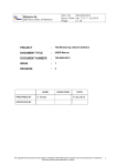
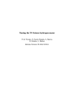
The following block diagram illustrates the interface that is the subject of this document. This
diagram is consistent with Figure 2.1 of [AD 01] but adds detail to the CLOA elements: HMaser, GPS, CRD, CRG, CVR, …etc.
In the first figure, the ALMA CLOA is shown before the addition of elements required for the
ALMA Phasing Project.
1 PPS
H-Maser
5MHz,
10 MHz
1 PPS distributor
1 PPS
GPS
1 PPS
Central
Reference
Generator
& Distributor
Phasing Interface
Cards
48 msec,
125 MHz
Correlator
10 MHz
Master
Laser
st
11stst1stLO
LO
1 LO
LO
Microwave
Microwave
Microwave
Microwave
Synthesizer
Synthesizer
Synthesizer
Synthesizer
(CVR)
Photonic Distribution
1: 66
1: 66
ML Photonic
Distribution
Laser
Laser
Laser
Laser
Synthesizer
Synthesizer
Synthesizer
Synthesizer
(SAS/LLC)
Local Oscillator
Subarray mapped to
Antennas
66
4:1
66
4:1
66
4:1
Antenna #1
Antenna #2
1: 66
Antenna #3
1: 66
CLOA
66
4:1
Antenna #66
Figure 3-1 - ALMA CLOA (shaded red box), with interface to Correlator and Antennas
indicated. Before ALMA Phasing Project elements are added.
The changes necessary to accommodate the ALMA Phasing Project are shown next.
ALMA Project
Interface Control Document
Between ALMA Phasing Project
And ALMA Computing
Doc #: ALMA- 05.11.00.00-70.35.25.00-A-ICD
Date: 2014-10-07
Status: Draft
(Draft, Pending, Approved, Released, Superseded, Obsolete)
Page:
13 of 44
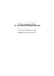
Figure 3-2 - ALMA CLOA (shaded red box), with interface to Correlator and Antennas
indicated, with ALMA Phasing Project elements added.
The added elements are the following:
•
•
•
•
•
Hydrogen Maser (H-Maser)
H-Maser Rack (HMR)
Change of 1 PPS from MFS to H-Maser
Change of 5 MHz now coming from the H-Maser to the MFS
Addition of 1 PPS from H-Maser to Correlator (CORR)
3.1.1 H-Maser Interface to Computing
The maser includes a software interface which is documented in [RD 01]. To monitor the health
of the maser, the ALMA Monitor and Control System shall use this interface to monitor and log
the parameters listed in Table 2 of this manual. This interface is fully described in [AD-02].
.
3.2 64-Antenna Correlator Upgrades
ALMA Project
Interface Control Document
Between ALMA Phasing Project
And ALMA Computing
Doc #: ALMA- 05.11.00.00-70.35.25.00-A-ICD
Date: 2014-10-07
Status: Draft
(Draft, Pending, Approved, Released, Superseded, Obsolete)
Page:
14 of 44
3.2.1 Introduction
The specification for the 64-Antenna Correlator [RD 10] includes a requirement that the
correlator provide “hooks” for VLBI. To take advantage of these hooks, various modifications
to the correlator are required. Hardware modifications to the correlator are documented
separately in [RD-07]. This section details the new CAN protocols required to implement the
APP. Existing Correlator CAN protocols are documented in [RD 04].
3.2.2 Interface to Computing
[RD 04] includes a section (section 16 in version D) describing the interface between the
“Correlator and Computing Correlator System”. The introductory part of this section provides a
general overview of the CAN interface between computing and correlator. This is not repeated
here. Also, certain existing CAN protocols, which are indispensable to implementing the
phasing interface, are not repeated here. The following sections describe only new capabilities
required for implementing phasing. Recall that a new type of card, the PIC, is added to the
correlator. Two such cards are required per quadrant. The PIC card shall also respond to all
“Protocols That Apply to All types of Nodes” (section 16.3 in [RD 11]).
3.2.2.1
Protocols Specific to LTA Nodes
Since the actual summing of signals from antennas takes place in the correlator cards, which are
controlled by the LTAs, some new protocols are required to control and monitor this
functionality. A short summary of the new protocols required includes:
• Provide a mask to specify which antennas are summed
• Provide the capability to substitute test data for normal data in the sum
• Provide the capability to control a switch which in turns provides the capability to inject
the sum into the correlator matrix in place of the 64th antenna.
• Provide data for mapping the sum from 8 bits to 2 bits.
• Provide a means of monitoring the status of the above commands
3.2.2.1.1
DOWNLOAD_ANTENNA_SUM_MASK: Function Code
2, Type 11
Type:
Description:
Typical Interval:
Broadcast, Data_msg_ID = 8, Func code 2, Structure type 11
Provides a mask to select which antennas to sum
Before the start of data taking
ALMA Project
Interface Control Document
Between ALMA Phasing Project
And ALMA Computing
Data in Data Messages:
Message
Payload
Bytes
Data[0]
Data[1]
Data[2]
Data[3]
Data[4]
Data[5]
Data[6]
Data[7]
Doc #: ALMA- 05.11.00.00-70.35.25.00-A-ICD
Date: 2014-10-07
Status: Draft
(Draft, Pending, Approved, Released, Superseded, Obsolete)
Page:
15 of 44
2 bytes
Fixed length message payloads = 8 bytes
Broadcast Setup
Header
Message
Message
8 bytes
First & Only Data
Message
Transmit using
Message ID 5
Transmit using
Message ID 8
Transmit using
Message ID 9
Data_msg_ID = 8
0 (spare)
Target mask 7 - 0
Target mask 15 - 8
Target mask 23 - 16
Target mask 31 - 24
Target mask 39 - 32
Target mask 47 - 40
Func_code=2
Struct_type 11
LS block size (bytes) = 8
MS block size (bytes) = 0
0 (spare)
0 (spare)
0 (spare)
0 (spare)
Mask Byte 0
|
|
|
|
|
|
Mask Byte 7
Byte 0 is the LS byte, corresponding to CAIs 7 down to 0, and so forth up through Byte 7 for
CAIs 63 down to 56. A one in a bit position specifies that the CAI is included in the sum. A
zero specifies that it is not. Bit 7 of byte 7 should always be zero since this antenna input is used
by the phasing system to input the sum into the correlator matrix. A 1 in this bit position will be
flagged as a warning in the status message. A zero in this position will always be downloaded to
hardware and returned as status by the firmware in the LTA.
This command does not require an “apply”. The mask is changed right after the command is
received.
3.2.2.1.2
Type:
Description:
Typical Interval:
Data in Data Messages:
SET_ANALOG_SUM_MODE: Function Code 11
Broadcast, Data_msg_ID = 8, Func code 11
Used to select between normal and test data
Before the start of data taking
2 bytes
This protocol directs the analog sum logic to provide either normal data or one of four possible
test data streams.
ALMA Project
Interface Control Document
Between ALMA Phasing Project
And ALMA Computing
Doc #: ALMA- 05.11.00.00-70.35.25.00-A-ICD
Date: 2014-10-07
Status: Draft
(Draft, Pending, Approved, Released, Superseded, Obsolete)
Page:
16 of 44
Fixed length message payloads = 8 bytes
Message
Payload
Bytes
Data[0]
Data[1]
Data[2]
Data[3]
Data[4]
Data[5]
Data[6]
Data[7]
Broadcast Setup
Message
Transmit using
Message ID 5
Data_msg_ID = 8
0 (spare)
Target mask 7 - 0
Target mask 15 - 8
Target mask 23 - 16
Target mask 31 - 24
Target mask 39 - 32
Target mask 47 - 40
Header
Message
Transmit using
Message ID 8
Func_code=11
MODE 0-4 (selects sum output type)
0 (spare)
0 (spare)
0 (spare)
0 (spare)
0 (spare)
0 (spare)
The following table identifies the input source selection options:
Data[1]
0
1
2
3
4
Sum Output Type
Antenna Sum (normal data)
Static logic level 0
Pseudo random data, sync'd to 16
msec tic
Pseudo random data, not sync'd to
tic
Binary counter
This type of flexibility on output data is similar to that provided in other parts of the correlator.
It has proven useful in measuring the reliability of the links between subsystems as well as aiding
with troubleshooting. In this instance, it will make it possible to evaluate the reliability of the
link to the PIC cards and downstream link.
This command does not require an “apply”. The switch is changed right after the command is
received.
3.2.2.1.3
Type:
Description:
Typical Interval:
Data in Data Messages:
SET_CIC_SUM_INPUT_SWITCH
Broadcast, Data_msg_ID = 8, Func code 12
Provides a bit to set the state of the CIC input switch
Before the start of data taking
2 bytes
ALMA Project
Interface Control Document
Between ALMA Phasing Project
And ALMA Computing
Doc #: ALMA- 05.11.00.00-70.35.25.00-A-ICD
Date: 2014-10-07
Status: Draft
(Draft, Pending, Approved, Released, Superseded, Obsolete)
Page:
17 of 44
There is an electronic switch in the Correlator Interface Cards, which allows for selection of two
possible inputs for the 64th antenna, CAI 63. The first is the normal data from CAI 63. The
second is the phased sum data from the correlator card. The hardware default, after a system
reset, is normal data, so that this protocol needs to be used only in phasing mode.
Fixed length message payloads = 8 bytes
Message
Payload
Bytes
Data[0]
Data[1]
Data[2]
Data[3]
Data[4]
Data[5]
Data[6]
Data[7]
Broadcast Setup
Message
Transmit using
Message ID 5
Data_msg_ID = 8
0 (spare)
Target mask 7 - 0
Target mask 15 - 8
Target mask 23 - 16
Target mask 31 - 24
Target mask 39 - 32
Target mask 47 - 40
Header
Message
Transmit using
Message ID 8
Func_code=12
Switch Position Bit (0 = normal data; 1 = phased sum data)
0 (spare)
0 (spare)
0 (spare)
0 (spare)
0 (spare)
0 (spare)
This command does not require an “apply”. The switch is changed right after the command is
received.
3.2.2.1.4
DOWNLOAD_SUM_SCALING_DATA
Summing the 2-bit data from the ALMA antennas in the observing Array will result in a sum
which has at most 256 possible values. To be fed back to the correlator or delivered to the PIC,
this sum must be again reduced to a 2-bit quantity with proper statistics (i.e. one of 4 states
representing -3, -1, +1 or +3, with Gaussian distribution).
The mapping of 256 to 4 values is a function of the number of antennas N and can be provided to
the LTA logic equivalently as a lookup table or as the 3 thresholds dividing the 4 output states,
and the limiting valid values. Even more simply, one can assume zero offset and provide a
single number, the positive threshold and assume the negative threshold is symmetrical.
Initially, we plan to implement the simplest choice. Details for this choice are presented in
Section 3.2.2.1.4.2.
3.2.2.1.4.1
Background information
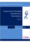
The summing hardware is capable of providing 4 sets (A through D) of two bit numbers for each
of two polarizations (P0 and P1) as shown in Figure 3-3 below. We expect that, for our
application, all four sets will be identical. The capability of making them different is provided,
ALMA Project
Interface Control Document
Between ALMA Phasing Project
And ALMA Computing
Doc #: ALMA- 05.11.00.00-70.35.25.00-A-ICD
Date: 2014-10-07
Status: Draft
(Draft, Pending, Approved, Released, Superseded, Obsolete)
Page:
18 of 44
however, since is it fairly simple to do so. The protocol to deliver the 8- to 2-bit mapping
information thus is applicable to one or more configurations as specified by a mask variable in
the headers. The interpretation of the mask bits is as shown in Figure 3-4 below.
NEW
TO PINS
TO PIC
P0SUMA[1:0]
M0SUM[7:0]
Add 64
Antennas
2K
SCALING
RAM
P0SUMB[1:0]
P0SUMC[1:0]
CONVERT
TO LVDS
TO CI
4 LVDS
WAFERS
P0SUMD[1:0]
P1SUMA[1:0]
M1SUM[7:0]
Add 64
Antennas
2K
SCALING
RAM
P1SUMB[1:0]
P1SUMC[1:0]
TO PIC
CONVERT
TO LVDS
TO CI
4 LVDS
WAFERS
P1SUMD[1:0]
Figure 3-3. Block diagram showing the scaling of the sum and routing of 2-bit results to the PIC and CI.
Figure 3-4. Sketch showing the mapping of the mask bits.
NB: There is no basis at present for thinking we need a separate map for the A and B channels
(i.e. the PIC should produce exactly what is fed back to the correlator), or for a separate map for
ALMA Project
Interface Control Document
Between ALMA Phasing Project
And ALMA Computing
Doc #: ALMA- 05.11.00.00-70.35.25.00-A-ICD
Date: 2014-10-07
Status: Draft
(Draft, Pending, Approved, Released, Superseded, Obsolete)
Page:
19 of 44
P0 and P1 (the polarization sums should be handled identically). Since C and D are not
connected, the mask would then always be 0xC3.
3.2.2.1.4.2
Type:
Description:
Typical Interval:
Data in Data Messages:
Message with one threshold
Broadcast, Data_msg_ID = 8, Func code 13
Provides threshold and mask for mapping 8-bit data to 2 bits
Before the start of data taking
3 bytes
The protocol we have selected to implement uses one threshold. It is described in this section.
Message
Payload
Bytes
Data[0]
Data[1]
Data[2]
Data[3]
Data[4]
Data[5]
Data[6]
Data[7]
Broadcast Setup
Message
Transmit using
Message ID 5
Data_msg_ID = 8
0 (spare)
Target mask 7 - 0
Target mask 15 - 8
Target mask 23 - 16
Target mask 31 - 24
Target mask 39 - 32
Target mask 47 - 40
mask:
pos2high_th:
Header
Message
Transmit using
Message ID 8
Func_code=13
Mask
pos2high_th
0 (spare)
0 (spare)
0 (spare)
0 (spare)
0 (spare)
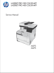
controls applicability as defined above (Figure 3-4)
the positive threshold. See figure below for details. At and above this
threshold, the memory output shall be 01 for data to the Station Interface
Card (SI) and 11 for data to the PIC.
ALMA Project
Interface Control Document
Between ALMA Phasing Project
And ALMA Computing
Doc #: ALMA- 05.11.00.00-70.35.25.00-A-ICD
Date: 2014-10-07
Status: Draft
(Draft, Pending, Approved, Released, Superseded, Obsolete)
Page:
20 of 44
Figure 3-5. Illustration of the effect of the threshold to the mapping of memory addresses (corresponds to
sums) to memory outputs (corresponds to scaled sum)
This command does not require an “apply”. The switch is changed right after the command is
received.
3.2.2.1.1
GET_SUM_STATUS
RCA
Description
0x1000, FC 14
Returns status information from all of the above commands
Typical Interval
Data
After executing above commands
8 bytes
GET: returns status info.
ALMA Project
Interface Control Document
Between ALMA Phasing Project
And ALMA Computing
Message
Payload
Bytes
Data[0]
Data[1]
Data[2]
Data[3]
Data[4]
Data[5]
Data[6]
Data[7]
Doc #: ALMA- 05.11.00.00-70.35.25.00-A-ICD
Date: 2014-10-07
Status: Draft
(Draft, Pending, Approved, Released, Superseded, Obsolete)
Page:
Control Message
(identical for both the
request and response )
Data
Messages
(All but last)
Message RCA
0x1000
Message RCA
0x1000
Func_code=14
Mask Byte 0
|
|
|
|
|
|
Mask Byte 7
0 (spare)
LS struct size (bytes)
MS struct size (bytes)
0 (spare)
0 (spare)
0 (spare)
0 (spare)
21 of 44
Last Data Message
… Message RCA
0x1001
MODE 0-4
Switch Position
Mapping Mask
pos2high_th
-pos2high_th
spare
spare
spare
Description of data in the message:
Mask Byte 0 to 7: The mask transmitted by the previous
DOWNLOAD_ANTENNA_SUM_MASK command.
Switch Position: The switch position transmitted by the previous
SET_CIC_SUM_INPUT SWITCH command
MappingMask: The mask transmitted by the previous
DOWNLOAD_SUM_SCALING_DATA command.
pos2high_th: The lowest numbered address having a memory contents of 01.
(Reference Figure 3-5.) This verifies that the LTA properly interpreted the
DOWNLOAD_SUM_SCALING_DATA command from the CCC.
-pos2high_th: The lowest numbered address having a memory contents of 11.
(Reference Figure 3-5.) This verifies that the LTA properly interpreted the
DOWNLOAD_SUM_SCALING_DATA command from the CCC.
Scale_err: This byte has value 0x01 if there are transitions in the sum scaling table
except at -pos2high_th, pos2high_th and between 0x7F and 00. (Reference Figure 3-5.)
This verifies that the LTA properly interpreted the
DOWNLOAD_SUM_SCALING_DATA command from the CCC.
After this command is executed, all status words are set to zero. This allows the CCC to tell
whether commands are being sent as expected.
ALMA Project
Interface Control Document
Between ALMA Phasing Project
And ALMA Computing
3.2.2.2
Doc #: ALMA- 05.11.00.00-70.35.25.00-A-ICD
Date: 2014-10-07
Status: Draft
(Draft, Pending, Approved, Released, Superseded, Obsolete)
Page:
22 of 44
Protocols Specific to PIC Nodes
Eight copies of a new card, the PIC, must be added to the correlator to provide a phasing
interface. Two cards are added to each quadrant, one for each polarization. The primary
function of the card is to format the sum data, received from the correlator cards, into a VLBIstandard VDIF format. A short summary of the new protocols required includes:
• A protocol to download required header information for the VDIF data frames
• A protocol to apply the above header information
• A protocol to monitor the time and status in the PIC card
• A pair of protocols to initiate and monitor a test for data quality into the PIC
• A protocol to monitor the sum-data statistics
• A protocol to control the PIC card (power on/off, etc.)
ALMA Project
Interface Control Document
Between ALMA Phasing Project
And ALMA Computing
3.2.2.2.1
(Draft, Pending, Approved, Released, Superseded, Obsolete)
Page:
23 of 44
DOWNLOAD_VDIF_HEADER
Broadcast, Data_msg_ID = 8, Func code 2, type 0
Used to download header for VDIF frame
Before the start of data taking
40 bytes
Type:
Description:
Typical Interval:
Data in Data Messages:
Message
Payload
Bytes
Doc #: ALMA- 05.11.00.00-70.35.25.00-A-ICD
Date: 2014-10-07
Status: Draft
Broadcast Setup
Message on Control
Channel
Header Message on
Data Channel
Data
Msg 0
Data
Msg 1
Data
Msg 4
Msg ID 8
Msg ID 8
Msg ID 9
PSN
(LSB)
PSN
PSN
PSN
PSN
Word 0
(LSB)
Word 0
Word 0
Word 0
Word 1
(LSB)
Word 1
Word 1
Word 1
(MSB)
Word 6 (LSB)
…
Transmit using
Message ID 5
Transmit using
Message ID 8
Data[0]
Data_msg_ID = 8
Func_code=2
Data[1]
Data[2]
Data[3]
Data[4]
0 (spare)
Target mask
Target mask
Target mask
7-0
15 - 8
23 - 16
Struct_type = 0
LS struct size (bytes)
MS struct size (bytes)
0 (“block nr 0”) *
Data[5]
Data[6]
Data[7]
Target mask
Target mask
Target mask
31 - 24
39 - 32
47 - 40
0 (not used)
eVLBI = 1
0 (not used)
PSN
PSN
PSN
(MSB)
Word 6
Word 6
Word 6
Word 7 (LSB)
Word 7
Word 7
Word 7 (MSB)
From the start of transmission by the CCC, it takes less than 4 msec for the transmitted data to be
downloaded into hardware.
In the VLBI community a particular standard, VDIF, is followed for writing data (additional info
may be found below and in [RD 05]). APP shall follow this standard. Additionally it shall
prepend a Packet Serial Number (PSN) to each packet to enable eVLBI.
Each Phasing Interface Card (PIC) will produce a stream of VLBI Data Interchange Format
(VDIF) packets. The rules governing the packet stream are rather complex in general. (See [RD
05] for all the details if you like.)
For the ALMA case, each PIC receives 2-bit data samples from each of the 32 62.5 MHz slices
of the 2 GHz IF from its quadrant of the correlator. With a factor of 2 for Nyquist sampling, each
PIC data stream thus produces
2bits/channel x 32 channels/sample x 2 x 62.5 Msamples/s
ALMA Project
Interface Control Document
Between ALMA Phasing Project
And ALMA Computing
Doc #: ALMA- 05.11.00.00-70.35.25.00-A-ICD
Date: 2014-10-07
Status: Draft
(Draft, Pending, Approved, Released, Superseded, Obsolete)
Page:
24 of 44
64 x 125 Mbits/second = 8000 Mb/s = 1000 MB/s = 29 * 59 B/s
The VDIF data packets must be a multiple of 8 B in length, and further, the data bits from each
second must be parceled equally into an integral number of packets. Since these packets will be
transmitted on a physical ethernet layer, that protocol imposes an additional limit of no more
than 9000 B/packet (including the VDIF header and UDP packet overhead). The CASPER
Roach design for the Ethernet implementation further restricts the VDIF portion to 8192.
Subject to these restrictions, the largest packet possible is 8000 B for a data rate of
(1000 MB/s) / (8000 B/packet) = 125000 packets/s
The Packet Serial Number is exactly 8 B that precede the VDIF header. The VDIF header is
exactly 32 bytes that precede the data. These fields and data portion are shown schematically in a
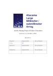
cartoon of a complete packet as shown in Figure 3-6.
In forming VDIF frames for the APP, the values received from the CAN protocol are used as
follows:
PSN
Word 0, bits 0 to 29
Word 0, bits 30
Word 0, bits 31
All “brown” bits
All “pink” bits
Word 4, bits0 to 23
Used for the PSN of the first transmitted frame. In subsequent frames, the PSN
increases by 1 per frame
Used to set the initial value of time in the timing generator (in the ROACH FPGA) at
the rising edge of the TE tic following the APPLY_VDIF_HEADER command. After
this, the time increments based on the 125 MHz correlator clock
Always zero in all frames.
Sets the initial value for this bit in the VDIF frame. The value of this bit can later be
changed via a bit in the CAN command SET_PIC_CONTROL. It can also be changed
to set to 1 if the hardware detects a problem that corrupts the data.
All bits shaded with the color brown in Figure 3-6 are identical to the corresponding
bits in the CAN message, for all frames. These are the same for all observations.
All bits shaded with the color pink in Figure 3-6 are identical to the corresponding
bits in the CAN message, for all frames. These may be set (by the observer) as
desired.
A “magic/sync” identifier that in effect identifies 224 “subversions”, of which we use
16 at ALMA
1.
For the ALMA PICs, the value will be 0xA5AE5X where the least significant
nibble is constructed as follows:
1.
bit 0: 0 = X-pol PIC, 1 = Y-pol PIC
2.
bits 1 and 2: ALMA BL quadrant number minus 1 (i.e. the quadrants
are named 1 through 4, so these bits will contain 0 through 3).
3.
bit 3: 1 = BL Correlator 0 = 2-ant correlator
2.
For Mark6 testing, the format is not finalized. However, it currently encodes
the nominal packet rate and information about test marks made in the data stream.
3.
For use in other applications, 0x000000 through 0x7FFFFF are available.
ALMA Project
Interface Control Document
Between ALMA Phasing Project
And ALMA Computing
Word 5
Words 6 and 7
Doc #: ALMA- 05.11.00.00-70.35.25.00-A-ICD
Date: 2014-10-07
Status: Draft
(Draft, Pending, Approved, Released, Superseded, Obsolete)
Page:
25 of 44
A repeating series of eight 32-bit words is provided in Word 5 as shown in Table 3
These words will provide the value for the packet serial number of the first transmitted
frame. Subsequent frames will increment this count by 1 per frame. Normally the
recorder does not record the PSN that precedes the VDIF packet proper.
ALMA Project
Interface Control Document
Between ALMA Phasing Project
And ALMA Computing
Doc #: ALMA- 05.11.00.00-70.35.25.00-A-ICD
Date: 2014-10-07
Status: Draft
(Draft, Pending, Approved, Released, Superseded, Obsolete)
Page:
26 of 44
Figure 3-6. VDIF frame format for the PIC.
ALMA Project
Interface Control Document
Between ALMA Phasing Project
And ALMA Computing
Data Frame #
within second
(bits 2 to 0)
0x0
Status
Word #
0
0x1
1
0x2
2
0x3
3
0x4
4
0x7 to 0x5
7 to 5
Doc #: ALMA- 05.11.00.00-70.35.25.00-A-ICD
Date: 2014-10-07
Status: Draft
(Draft, Pending, Approved, Released, Superseded, Obsolete)
Page:
27 of 44
Field
Definitions
Bit 0:
Bit 1:
Bit 2:
Bit 3 3:
Bit 4:
Bit 5:
Bit 6:
Bits 8 - 7:
others
Bits 31 – 24
Bits 31 to
28:
Bits 27 to 0:
Bits 31 to
28:
Bits 27 to 0:
Bits 31 to
28:
Bits 27 to 0:
Bits 31 to
16:
Bits 15 to 6
Bits 5 to 0:
spare
Field
Description
Bad Packet when = 1
TE Error when = 1
125 MHz MMCM lock error when = 1
FPGA over-temperature error when = 1
SEU Error when = 1
Delay controller error when = 1
Data Kill Enable when = 1 (first 2 usec of data in frame 0 0 = 0)
Data source
when = 00 => normal data from summer
when = 01 => incrementing count from PIC counter
when = 10 => pseudo-random data from PIC pseudo-random data
generator
when = 11 => always zero
spare
FPGA personality version number
0x1
GPS offset from PIC 1PPS
0x2
Maser offset from PIC 1PPS
0x3
TE offset from PIC 1PPS (measured at seconds 0, 6, 12, …)
0x3000
FPGA_temperature
Temp(oC) = ((FPGA_temperature) * 503.975/1024)-273.15
not meaningful
In the VDIF frame, these words have values of 0x0000_0007,
0x0000_0006 and 0x0000_0005 respectively
Table 3. Definition of status words delivered in Word 5 of the VDIF frame as a function of Data Frame
Number within second, bits 2 to 0.
In some cases, fewer than 32 channels will need to be recorded. In these cases, the frame rate
and/or length are adjusted to meet the VDIF requirements. Table 3-1, below, summarizes the
frame rate and length for all APP cases.
ALMA Project
Interface Control Document
Between ALMA Phasing Project
And ALMA Computing
Doc #: ALMA- 05.11.00.00-70.35.25.00-A-ICD
Date: 2014-10-07
Status: Draft
(Draft, Pending, Approved, Released, Superseded, Obsolete)
Page:
28 of 44
Table 3-4. Summary of the frame timing and contents as a function of the number of IF channels.
The C167 depends on the CCC to supply all bits of the header except
• The Data Frame # within second (the FPGA can supply this because we always start at a
1-second boundary where this field must be zero
• The least significant nibble of the Magic Alignment word (see entry for Word 4 above)
• The Status Word
As a result, the CCC supplies the following (lsb on the left):
PSN[0] =
PSN[1] =
words[0]
words[1]
words[2]
words[3]
words[4]
words[5]
words[6]
words[7]
{psn_lower - 32b}
{psn_upper - 32b}
= {sec_from_ref_epoch (apply TE) - 30b}, {0 - 1b}, {0 (invalidity) - 1b}
= {0 - 24b}, {ref_epoch (semester since 2000) - 6b}, {0 - 2b}
= {frame_bytes (1004 or 629) - 24b}, {n_chan_log2 - 5b}, {0 - 3b}
= {station_id - 16b}, {thread_id - 10b}, {1 - 1b}, {0 - 5b}
= {0xA5EA50 (upper magic word) - 24b}, {0x02 (EDV) - 8b}
= {0 - 32b}
= {psn_lower - 32b}
= {psn_upper - 32b}
ALMA Project
Interface Control Document
Between ALMA Phasing Project
And ALMA Computing
Doc #: ALMA- 05.11.00.00-70.35.25.00-A-ICD
Date: 2014-10-07
Status: Draft
(Draft, Pending, Approved, Released, Superseded, Obsolete)
Page:
29 of 44
3.2.2.2.2
GET _DOWNLOAD_VDIF_HEADER_STATUS: RCA
0x20503
RCA
Description
Typical Interval
Data
Message
Payload
Bytes
Data[0]
Data[1]
Data[2]
Data[3]
Data[4]
Data[5]
Data[6]
Data[7]
2 05 03
Status resulting from DOWNLOAD_VDIF_HEADER commands.
Rare.
2 bytes
Reply Message Contents
Message RCA 0x20503
VDIF status
spare
A new DOWNLOAD_VDIF_HEADER command should not be sent until the previous one has been processed, so
CCC should check this status prior to issuing a new DOWNLOAD_VDIF_HEADER command. Possible VDIF
status values are
Bit 0:
= 1: not done
= 0: done
Other bits:
Not used
ALMA Project
Interface Control Document
Between ALMA Phasing Project
And ALMA Computing
3.2.2.2.3
Type:
Description:
Typical Interval:
Data in Data Messages:
Doc #: ALMA- 05.11.00.00-70.35.25.00-A-ICD
Date: 2014-10-07
Status: Draft
(Draft, Pending, Approved, Released, Superseded, Obsolete)
Page:
30 of 44
APPLY_VDIF_HEADER command: Function Code 3
Broadcast, Data_msg_ID = 8, Func code 3
Used to apply the frame information
Before the start of data taking
2 bytes
Message
Payload
Bytes
Broadcast Setup
Message
Transmit using
Message ID 5
Header
Message
Transmit using
Message ID 8
Data[0]
Data[1]
Data[2]
Data[3]
Data[4]
Data[5]
Data[6]
Data[7]
Data_msg_ID = 8
0 (spare)
Target mask 7 - 0
Target mask 15 - 8
Target mask 23 - 16
Target mask 31 - 24
Target mask 39 - 32
Target mask 47 - 40
Func_code = 3
LS byte of # events
MS byte of # events
0 (spare)
0 (spare)
0 (spare)
0 (spare)
0 (spare)
This command causes the transmitted VDIF header to be applied at the rising edge of the next
PIC 1PPS. Since the data is already downloaded in hardware, the apply is instantaneous.
Assuming that the CCC transmits the data right after the TE that immediately precedes the PIC
1PPS, the apply delay is 48 msec. The first two data bytes reserve storage for a TE count which
will NOT be implemented initially. The TE count would allow the header to be applied after
some number of TEs. This type of countdown is implemented in a few other Correlator CAN
commands, but, in practice, has never been used.
The command should be transmitted by the early in the TE cycle before the TE at which the
“apply” is to occur. In addition, the TE at which the “apply” is to occur should occur on an even
second. TE is coincident with 1 PPS at seconds 0, 6, 12, …54.
ALMA Project
Interface Control Document
Between ALMA Phasing Project
And ALMA Computing
3.2.2.2.4
RCA
Description
Typical Interval
Data
Message
Payload
Bytes
Data[0]
Data[1]
Data[2]
Data[3]
Data[4]
Data[5]
Data[6]
Data[7]
Doc #: ALMA- 05.11.00.00-70.35.25.00-A-ICD
Date: 2014-10-07
Status: Draft
(Draft, Pending, Approved, Released, Superseded, Obsolete)
Page:
31 of 44
GET_APPLY_VDIF_HEADER_STATUS: RCA 0x20504
2 05 04
Status resulting from APPLY_VDIF_HEADER commands.
Rare.
2 bytes
Reply Message Contents
Message RCA 0x20504
Apply VDIF status
spare
Provides the status for the APPLY_VDIF_COMMAND. The status word can take on the
following values:
Bits 2 to 0:
PICApplyState = 6;
// error: FPGA write error!
PICApplyState = 5;
//idle, no download or apply received
PICApplyState = 4
//received a download
PICApplyState = 3;
//set state to waiting on 1-msec loop
PICApplyState = 2;
//waiting for TE
PICApplyState = 1;
//error: no download prior to apply!
PICApplyState = 0;
//apply is complete
If PICApplyState == 6, then, after transmission to the CCC it is changed to 5
Bit 7:
ROACH_write_error:
= 1 indicates an error writing to the FPGA (either during the
APPLY_TIME_DATE or APPLY_VDIF_HEADER commands
= 0 no write errors
This bit is set to zero after transmission to the CCC
Other bits:
Not used
ALMA Project
Interface Control Document
Between ALMA Phasing Project
And ALMA Computing
3.2.2.2.5
Type:
Description:
Typical Interval:
Data in Data Messages:
Message
Payload
Bytes
Data[0]
Data[1]
Data[2]
Data[3]
Data[4]
Data[5]
Data[6]
Data[7]
Doc #: ALMA- 05.11.00.00-70.35.25.00-A-ICD
Date: 2014-10-07
Status: Draft
(Draft, Pending, Approved, Released, Superseded, Obsolete)
Page:
32 of 44
SET_PIC_CONTROL
Broadcast, Data_msg_ID = 8, Func code 2, type 1
Used to download most control bits required by the PIC
Before the start of data taking
16 bytes
Broadcast Setup
Message on Control
Channel
Header Message on
Data Channel
Transmit using
Message ID 5
Transmit using
Message ID 8
Data_msg_ID = 8
0 (spare)
Target mask 7 - 0
Target mask 15 - 8
Target mask 23 - 16
Target mask 31 - 24
Target mask 39 - 32
Target mask 47 - 40
Func_code=2
Struct_type = 1
LS struct size (bytes)
MS struct size (bytes)
0 (“block nr 0”) *
0 (not used)
eVLBI = 1
0 (not used)
Data
Msg 0
Data
Msg 4
Msg ID 8
Msg ID 9
CTRL[0]
CTRL[1]
CTRL[2]
CTRL[3]
CTRL[4]
CTRL[5]
CTRL[6]
CTRL[7]
CTRL[8]
CTRL[9]
CTRL[10]
CTRL[11]
CTRL[12]
CTRL[13]
CTRL[14]
CTRL[15]
Various control bits are required to set the operating mode of the PIC. These are provided in the
CTRL bytes above. The meaning of the bits in the CTRL bytes is detailed in the table below
Control Byte
Num
0
Bits
Name
Function
Note
1 -0
PWR
2
LDR
3
GRS
4
TGS
10 or 11= NOP (bit 1 is an enable)
1
00 = power off ROACH;
01 = power on ROACH
Rising edge = reload ROACH personality
Note: this feature is not functional as a 2014-4-21.
Please use the power bits above to reload the
personality
0 = no effect; 1 = reset ROACH registers
Note: Low level function used by the microprocessor.
Not useful from the CCC
Rising edge: start the timing generator clocks at the next
ALMA Project
Interface Control Document
Between ALMA Phasing Project
And ALMA Computing
5
7-6
1
1-0
2
3
2
3
5-0
7-0
4
4-0
5
0
Doc #: ALMA- 05.11.00.00-70.35.25.00-A-ICD
Date: 2014-10-07
Status: Draft
(Draft, Pending, Approved, Released, Superseded, Obsolete)
Page:
33 of 44
1 PPS rising edge.
Note: Low level function used by the microprocessor.
The CCC starts the timing generator with the
APPLY_TIME_DATE command
FMS
Rising edge: start transmitting packets at next 1 PPS
Falling edge: stop transmitting packets at end of current
packet.
Note: Low level function used by the microprocessor.
The CCC normally starts the formatter with the
APPLY_VDIF_HEADER command.
DOUT 00 = packets contain normal data
01 = packets contain incrementing word count
10 = packets contain 64-bit pseudo-random data
TM
00 = no input data tests
01 = test against pseudo-random data pattern
10= measure input statistics
RSD
Re-seed option for PRN test data generator
0 = PRN test generator free-runs
1 = PRN test generator re-seeds every TE
GrsFm 1 = reset data_formatter in FPGA
0 = no reset
ICH
Which of 64 input data streams to check for PRN
STL
How long to measure statistics. Valid entries are 1 to
127.
SCH
Number of input channels for which to measure
statistics, given as log2_nchan. Consistent with
correlator mode definitions, we always start with
channel 0. (So a 5 means 32 channels, a 4 means 16
channels, etc.)
NVLD Value to insert into Word 0, bit 31 of the data frame,
indicating data valid or not.
Note: The value that the CCC downloads for this bit is
logically ORed, by the microprocessor, with some
locally measured status bits. The following conditions
can cause NVLD =1 in the transmitted data frame:
1. NVLD = 1 from the CCC;
2. The frame clock on the FPGA is out-of-lock
2
2
ALMA Project
Interface Control Document
Between ALMA Phasing Project
And ALMA Computing
Others
Doc #: ALMA- 05.11.00.00-70.35.25.00-A-ICD
Date: 2014-10-07
Status: Draft
(Draft, Pending, Approved, Released, Superseded, Obsolete)
Page:
34 of 44
with the Maser 125 MHz;
3. The FPGA reports an over-temperature error
(this will eventually result in the ROACH being
powered off.)
spare
Notes:
1. This will take approximately 30 seconds
2. Statistics measurement will begin when a control command, with valid entries in both the
STL and SCH fields, is received, even if an acquisition is already in progress.
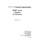
3. The suggested start-up procedure for the PIC is
a. Power on the ROACH (0x01 to control byte 0) and wait 40 seconds to complete
b. Align the FPGA’s internal 1PPS signal with the external world by sending an
APPLY_TIME_DATE CAN command in the TE immediately before second 0 or
second 6, or second 12, … See the timing diagram, Figure 3-7, for additional
details.
c. Do a GET_TIME_DATE command to check that the time was properly set
d. Wait a few TEs and then do a GET_PIC_STATUS command. Check the sampled
1PPS counter (Bytes 56 to 59). The value should be ((# TEs * 6*106) – 1).
e. Provide time information by executing the following two CAN commands
i. DOWNLOAD_VDIF_HEADER
ii. GET_DOWNLOAD_VDIF_HEADER_STATUS
f. Apply the time information (“seconds from reference epoch” and “packet serial
number”) during the TE that immediately precedes the TE when data taking is to
start. Data taking must start at second 0, or 6, or, 12… … See the timing
diagram, Figure 3-8, for additional details. This is done with the following two
CAN commands:
i. APPLY_VDIF_HEADER
ii. GET_APPLY_VDIF_HEADER_STATUS
g. Statistics should be measured at appropriate times as dictated by the astronomical
observation and operational concerns, keeping in mind the wise use of the CAN
bus bandwidth.
Statistics measurement will begin when a control command with valid entries is received.
ALMA Project
Interface Control Document
Between ALMA Phasing Project
And ALMA Computing
Doc #: ALMA- 05.11.00.00-70.35.25.00-A-ICD
Date: 2014-10-07
Status: Draft
(Draft, Pending, Approved, Released, Superseded, Obsolete)
Page:
35 of 44
Figure 3-7. Timing diagram which provides details in synchronizing the internal 1PPS to the external timing reference
ALMA Project
Interface Control Document
Between ALMA Phasing Project
And ALMA Computing
Doc #: ALMA- 05.11.00.00-70.35.25.00-A-ICD
Date: 2014-10-07
Status: Draft
(Draft, Pending, Approved, Released, Superseded, Obsolete)
Page:
36 of 44
Figure 3-8. Timing diagram which provides details in synchronizing “seconds from reference epoch” and “packet serial number” to the internal timing
references.
ALMA Project
Interface Control Document
Between ALMA Phasing Project
And ALMA Computing
3.2.2.2.6
Doc #: ALMA- 05.11.00.00-70.35.25.00-A-ICD
Date: 2014-10-07
Status: Draft
(Draft, Pending, Approved, Released, Superseded, Obsolete)
Page:
37 of 44
GET_PIC_Status
RCA
Description
0x1000, FC 3
Returns the status from the addressed PIC
Typical Interval
Data
Provided for monitoring and troubleshooting.
variable number of bytes
GET: the PIC returns the status data.
Message
Payload
Bytes
Data[0]
Data[1]
Data[2]
Data[3]
Data[4]
Data[5]
Data[6]
Data[7]
Control Message
(identical for both the
request and response )
Data
Messages
(All but last)
Message RCA
0x1000
Message RCA
0x1000
Func_code = 3
0 (spare)
LS block size (bytes)
MS block size (bytes)
LS block offset (bytes)
MS block offset (bytes)
0 (spare)
0 (spare)
STAT[0]
STAT[1]
STAT[2]
STAT[3]
STAT[4]
STAT[5]
STAT[6]
STAT[7]
Last Data Message
… Message RCA
0x1001
STAT[N-8]
STAT[N-7]
STAT[N-6]
STAT[N-5]
STAT[N-4]
STAT[N-3]
STAT[N-2]
STAT[N-1]
This protocol returns PIC status bits. The meaning of the status bits is detailed below. The
Block Size and Block Offset in the control message are provided by the CCC to indicate which
part of the table it wants in the reply. For example, block size of 8 and offset of zero returns only
the PSN. Block size of 8 and offset of 52 returns the PRN error count and environmental
monitors. Thus, for testing/debugging, access to any part of the table is possible. In operations,
the VOM will normally request the beginning of the table to verify timing (probably 56 bytes);
during setup, it will probably request state statistics once and retrieve the full table sometime
later. The table entries are aligned on 4-byte boundaries so that parsing of this information is
easy for the likely use cases.
Status
Byte
Num
0–3
Bits Name
Function
All
PSN LSW captured at last TE
PSN
Note
ALMA Project
Interface Control Document
Between ALMA Phasing Project
And ALMA Computing
4-7
8 -39
40 – 43
44– 47
48 – 51
52
53
All
All
All
All
All
All
All
PSN
VDIF
1PM
1PG
1PP
PRNE
ENV0
54-55
56
57 – 58
59
All
All
All
30
1-0
ENV
1PTE
1PTE
1PTE
60
61 – 63
64 –
All
447
Notes:
SSTA
STA
Doc #: ALMA- 05.11.00.00-70.35.25.00-A-ICD
Date: 2014-10-07
Status: Draft
(Draft, Pending, Approved, Released, Superseded, Obsolete)
Page:
38 of 44
PSN MSW captured at last TE
VDIF frame header captured at the last TE
2
Maser 1PPS offset from PIC 1 PPS
GPS 1PPS offset from PIC 1 PPS
TE @ 1PPS offset from PIC 1 PPS
PRN error count
Bit 0: = 0 means ROACH is off; = 1 means ROACH is on
Bit 1: = 0 means ROACH is not operational; = 1 means ROACH
is operational, i.e., ready for commands.
Bit 2: = 0 means no temperature warning; = 1 means temperature
warning threshold (~45oC) has been exceeded
Bit 3: = 0 means no temperature error; = 1 means temperature
error threshold (~50oC) has been exceeded. The ROACH board
is powered down by the C167 when this occurs.
Bit 4: = 0 means no SEU error; = 1 means that a CRC error has
been detected in the FPGA personality, likely caused by a Single
Event Upset (SEU). This serves as a warning that the FPGA
may not function correctly, but no operational changes are made
as a result of this error.
Bits 5 to 7: spare
Environmental Monitors, spare
Sampled PIC 1PPS counter, LSB
Sampled PIC 1PPS counter, middle bytes
Sampled PIC 1PPS counter, most significant nibble (bits 3 to 0)
Statistics status:
0: valid
1: in process
2: error (invalid request)
3: stale (when valid statistics have been followed by
another SET_PIC_CONTROL command, i.e., new
statistics are being calculated and old statistics are in
microprocessor memory.)
Spare
Statistics:
32 channels x 4 states/channel x 3bytes/state
1
ALMA Project
Interface Control Document
Between ALMA Phasing Project
And ALMA Computing
Doc #: ALMA- 05.11.00.00-70.35.25.00-A-ICD
Date: 2014-10-07
Status: Draft
(Draft, Pending, Approved, Released, Superseded, Obsolete)
Page:
39 of 44
1. The time to acquire these will vary with the statistics integration time, STL, and with the
number of channels requested: 1, 2, 4, 8, 16 or 32. Sixteen bits for statistics should be
sufficient since, even with a 1-msec acquisition window, counts occupy about 16 bits,
with about 8 of those being noise.
2. To avoid ambiguities in the header timing, the PIC status request should be sent shortly
after a TE so that the result is received before the next TE. According to Table 3-1, the
packet duration is ALWAYS an integral number of TEs (300 to 6000) and this header
refers to the first one of the group. (Ie the first datum is at the time indicated in the
header.
3.2.2.3
Protocols Specific to SCC Nodes
The phase of the digital local oscillators (DLOs) in the TFBs is key to phasing ALMA. Phase
updates to these DLOs need to be updated periodically based on a fairly complex measurement
process.
A command already exists to download phase commands to the DLOs. However, the current
command to apply the phases has undesirable side-effects for ALMA Phasing. A new command
without these side-effects is described below.
3.2.2.3.1
Type:
Description:
Typical Interval:
Data in Data Messages:
APPLY_TFB_PHASES
Broadcast, Data_msg_ID = 8, Func code 12 (0xC)
Used to apply the frame information
Before the start of data taking
2 bytes
Message
Payload
Bytes
Broadcast Setup
Message
Transmit using
Message ID 5
Header
Message
Transmit using
Message ID 8
Data[0]
Data[1]
Data[2]
Data[3]
Data[4]
Data[5]
Data[6]
Data_msg_ID = 8
0 (spare)
Target mask 7 - 0
Target mask 15 - 8
Target mask 23 - 16
Target mask 31 - 24
Target mask 39 - 32
Func_code = 12 (0xC)
LS byte of # events
MS byte of # events
configNum
0 (spare)
0 (spare)
0 (spare)
ALMA Project
Interface Control Document
Between ALMA Phasing Project
And ALMA Computing
Data[7]
Target mask
47 - 40
Doc #: ALMA- 05.11.00.00-70.35.25.00-A-ICD
Date: 2014-10-07
Status: Draft
(Draft, Pending, Approved, Released, Superseded, Obsolete)
Page:
40 of 44
0 (spare)
This command causes the transmitted TFB phases to be applied at the rising edge of the next TE.
The first two data bytes reserve storage for a TE count which will NOT be implemented initially.
The TE count would allow the phases to be applied after some number of TEs. This type of
countdown is implemented in a few other Correlator CAN commands, but, in practice, has never
been used. The next byte, configNum, specifies the one applicable configuration number (0 to
15). A configuration mask is not supplied since the CCC will always deal with updating phases
one configuration at a time. This also simplifies the software
The command should be transmitted by the early in the TE cycle before the TE at which the
“apply” is to occur.
3.2.2.3.1
RCA
Description
Typical Interval
Data
Message
Payload
Bytes
Data[0]
Data[1]
Data[2]
Data[3]
Data[4]
Data[5]
Data[6]
Data[7]
GET _APPLY_TFB_PHASES_STATUS: RCA 0x2050A
2 05 0A
Status resulting from APPLY_VDIF_HEADER commands.
Rare.
2 bytes
Reply Message Contents
Message RCA 0x2050A
Apply TFB Phases status
spare
Provides the status for the APPLY_TFB_PHASES command. The status word can take on the
following values:
• 0x02 No phases were received (failure) (or none since the last apply – do we want
this?)
• 0x01 Waiting for TE rising edge (pending)
• 0x00 phases have been applied (success)
ALMA Project
Interface Control Document
Between ALMA Phasing Project
And ALMA Computing
Doc #: ALMA- 05.11.00.00-70.35.25.00-A-ICD
Date: 2014-10-07
Status: Draft
(Draft, Pending, Approved, Released, Superseded, Obsolete)
Page:
41 of 44
After transmitting a “success” indication, the state is changed so that another monitor without
another apply command would result in the “no phases were received” monitor word. So the
normal sequence is as follows:
APPLY_TFB_PHASES
GET_APPLY_TFB_PHASES_STATUS (get “waiting” for a response)
GET_APPLY_TFB_PHASES_STATUS (get “waiting” for a response)
.
.
.
GET_APPLY_TFB_PHASES_STATUS (get “success” for a response)
.
.
.
APPLY_TFB_PHASES
GET_APPLY_TFB_PHASES_STATUS (get “waiting” for a response)
GET_APPLY_TFB_PHASES_STATUS (get “waiting” for a response)
.
.
.
GET_APPLY_TFB_PHASES_STATUS (get “success” for a response)
The sequence that will result in a failure indication is as follows:
APPLY_TFB_PHASES
GET_APPLY_TFB_PHASES_STATUS (get “waiting” for a response)
GET_APPLY_TFB_PHASES_STATUS (get “waiting” for a response)
.
.
.
GET_APPLY_TFB_PHASES_STATUS (get “success” for a response)
GET_APPLY_TFB_PHASES_STATUS (get “failure” for a response)
3.2.3 Other Interfaces to PIC
ALMA Project
Interface Control Document
Between ALMA Phasing Project
And ALMA Computing
Doc #: ALMA- 05.11.00.00-70.35.25.00-A-ICD
Date: 2014-10-07
Status: Draft
(Draft, Pending, Approved, Released, Superseded, Obsolete)
Page:
42 of 44
In addition to the CAN interface, the PIC cards have several other interfaces available. These
may be useful for engineering purposes. None of them require software from the Computing
IPT. However, they are Ethernet network interfaces, so ALMA Computing needs to be aware
that there may be a need to place them on the ALMA network or a private network connected to
the Engineering Port for use by engineers for troubleshooting and maintenance.
3.3 Optical Fiber Link System Interface
The purpose of this sub-system is to transmit the antenna sum data from the AOS to the OSF
while using minimal fiber resources. The eight 10 GbE data streams are wavelength-divisionmultiplexed onto one fiber at the AOS. This data is transmitted to the OSF where it is demultiplexed and routed to the appropriate recorder sub-system. The optical fiber link system (a
pair of a transmitter and a receiver) is fully symmetric and the two devices are inter-changeable
as they are totally in the same design. The device has no packet monitoring capability, so it is a
passive participant in the VLBI phasing system.
Manufacturer: Elex Engineering
Model Number: XW-100 (both the transmitter and the receiver)
3.3.1 Interface to Computing
The details of this interface are fully described in [AD-02].
3.4 VLBI Recorder Interface
The function of the recorder subsystem is to record, on computer disks, the antenna sum data that
is computed by the correlator and transmitted via the optical fiber link system. The disks are
then shipped to a correlator facility, such as Haystack Observatory, to be correlated with data
from other VLBI sites.
3.4.1 Subsystem Description
The recorder selected for the APP is the Mark 6 VLBI Data System. This system is a disk-based
recording system to support capturing digital data from VLBI observations up to 16Gbps
sustained data rate to an array of 32 disks. Each of the four recorders that will comprise the
APP record system has the following properties
ALMA Project
Interface Control Document
Between ALMA Phasing Project
And ALMA Computing
Doc #: ALMA- 05.11.00.00-70.35.25.00-A-ICD
Date: 2014-10-07
Status: Draft
(Draft, Pending, Approved, Released, Superseded, Obsolete)
Page:
43 of 44
Purpose: The Mark 6 VLBI data system is a disk-based recording system to support capturing
digital data from VLBI observations up to 16Gbps sustained data rate to an array of 32 disks.
Data interface: Four 10GigE connections from data source
Maximum input data rate: 16Gbps; maximum ~4Gbps per 10GigE port
Data recording media: 32 disks configured in four removable 8-disk modules (3.5” SATA)
M&C interface: Gigabit Ethernet
M&C protocol: VSI-S; alternate XML interface planned
Figure 3-9. Photo of one of four recorders required for the APP.
Data capacity: When populated with 32 2TB standard SATA disks, an aggregate 16Gbps input
data stream can be recorded continuously for ~8 hours before disk modules are filled.
3.4.2 Interface to Computing
Connection to Ethernet required: Each recorder requires a 1GbE network connection and
address, and uses one server port for the application. No CAN bus connection is required. The
recorder must be able to connect to a server running the NTP protocol
Software requirements: During development, the recorders use Red Hat Enterprise Linux.
MIT has a license, but, as these get transferred to ALMA, then ALMA shall
ALMA Project
Interface Control Document
Between ALMA Phasing Project
And ALMA Computing
Doc #: ALMA- 05.11.00.00-70.35.25.00-A-ICD
Date: 2014-10-07
Status: Draft
(Draft, Pending, Approved, Released, Superseded, Obsolete)
Page:
44 of 44
supply licenses from Red Hat.
The protocol details of the interface with Computing are fully described in [AD-02].
The control code is an APP deliverable and thus the ALMA ICT is not responsible for
developing this interface.