1
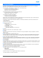
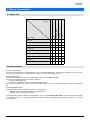
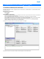
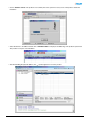
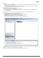
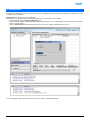
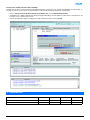
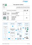
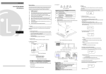
5
Tebis application software
STG51x Radio smoke detector
STG54x Radio heatstroke
Electrical / Mechanical characteristics: see product information
Product reference Designation
TP device
RF device
ETS version
TG510A
Battery-operated smoke detector
TG511A
Mains-powered smoke detector 230V AC
ETS 3 > 3.0f
TG540A
Battery-operated heatstroke
ETS 4 > 4.0.2
TG541A
Mains-powered heatstroke 230V AC
TG510A / TG511A
TG540A / TG541A
Output modules
KNX / EIB
Media coupler TR131
Loads connected
Lighting control
Shutters and blinds control
Heating control
Gateway between the RF
products and the TP
products in a KNX
installation
Priority
Scene
Configuration and
parameter setting of
radio products by ETS
Visualisation system
Fire alarm
Faulty product alarm
Battery status indication
Transmission of radio
controls
Diagnosis
Summary
1. Function Description ......................................................................................................................................................... 2
2. Objects and parameters.................................................................................................................................................... 4
2.1 Objects List.................................................................................................................................................................. 4
2.2 Alarm functions............................................................................................................................................................ 4
2.3 Parameters .................................................................................................................................................................. 5
3. Configuration with TR131 (ETS 3 Version > 3.0f / ETS 4 > 4.0.2).................................................................................... 6
3.1 Installation and addressing of the media coupler ........................................................................................................ 6
3.2 Addressing and download of the RF devices .............................................................................................................. 7
4. Factory reset ................................................................................................................................................................... 10
5. Characteristics ................................................................................................................................................................ 11
TG510A / TG511A / TG540A / TG541A
1
6T 8007-02a
1. Function Description
The smoke or heat (temperature) detector plays a role in the protection of buildings against the risk of fire. If something is
detected, they emit an audible alarm and send the information to the KNX system.
The smoke detector and heat detector can detect smoke or heat in different ways:
• Local detection (not integrated in a network)
• Detection by a network of cabled wired detectors
• Detection by a network of radio detectors
The following information is sent when smoke or heat is detected:
• Fire alarm information (smoke or temperature)
• Lighting, shutter, heating or scene controls
Two other types of information are available:
• Faulty product information (Faulty product)
• Low battery (for TG510A / TG540A only)
These products can be integrated into an installation configured by TR131 with the ETS media coupler. The KNX radio link is
unidirtectional in use mode and bi-directional in configuration mode.
The application software STG54x and STG51x enable the command types emitted after an alarm has been detected to be
configured individually.
The main functions are the following:
■ Emission of commands
• Lighting control
• ON, OFF, ON / OFF, Timer, Priority
• Shutters / Blinds control
• Up, Down
• Set point selection (Heating)
• ON / OFF, Comfort Priority or Frost protection
■ Scene
This function is used to emit scenes to different types of outputs.
■ Priority
This function sends priority-start or priority-stop commands. The forcing action depends on the type of application controlled:
Lighting, Heating.
■ Fire / smoke alarm (for TG510A / TG511A only)
This function signals a fire alarm using a heat detector. In case of alarm, a message is sent immediately and is then repeated
every minute. Without an alarm, the detector emits one message per day to indicate that the product is functioning properly.
■ Fire / heat alarm (for TG540A / TG541A only)
This function enables the indication of a fire alarm signaled by a heat detector. In case of alarm, a message is sent immediately
and is then repeated every minute. Without an alarm, the detector emits one message per day to indicate that the product is
functioning properly.
■ Faulty product
This function signals that the product is faulty after a self-diagnosis (Faulty product or measurement chamber polluted). If a fault
is signalled, a message is emitted immediately and is then repeated every 2 hours. When there is no fault, the detector sends a
message each day to indicate that the product is functioning properly.
■ Battery status indication
The detector sends this information during startup (battery change), or every 12 hours and when the 1 button is pushed if the
battery is low. The program remains saved when the batteries are changed.
■ Integration into a smoke or heat detector network
The smoke or heat detectors can be integrated into one of the following networks*:
• Wired network
• Radio network
• Hybrid network (wired and radio)
The alarm messages can be exchanged among the detectors in the network.
* For further information, see product user manual.
TG510A / TG511A / TG540A / TG541A
2
6T 8007-02a
Example of several detectors positioned in the network.
TG510A
TG510A
TG510A
TG500x / TG530A
TG500x / TG530A
TG541A
TG511A
TG511A
TG501x / TG531A
TG501x / TG531A
REMARK:
Only connect together smoke or heat detectors with the same type of power supply!
For example: TG510A model with TG500x / TG530A = Battery
or TG511A model with TG501x / TG531A = 230 V
Notes:
• To monitor a network of wired and/or radio detectors, only one KNX detector must be used in this network. In this case, if
the alarm is triggered in this network, it is the KNX detector that will send the KNX lighting, shutter or heating commands
and the alarm indication
• All the detectors, which in case, of a fire alarm being indicated should emit KNX commands that must be configured in KNX,
even if they have already been configured and integrated into a network of smoke or heat detectors
• To identify each detector in the KNX system in a unique way, each detector must be connected to the KNX installation. Unit
identification is only possible with radio detectors
• A factory reset of products by ETS only erases the KNX links. The existing links (non KNX) between the different detectors
are not erased
TG510A / TG511A / TG540A / TG541A
3
6T 8007-02a
2. Objects and parameters
2.1 Objects List
Timer
Scene
Heating
X
Shutters / blinds
ON / OFF
Timer
Object name
ON / OFF
Function
X
X
Slat angle / Stop
X
Up / Down
X
Scene
X
Priority
X
X
Battery status indication
X
X
X
X
X
Fire alarm
X
X
X
X
X
Faulty product alarm
X
X
X
X
X
2.2 Alarm functions
■ Fire / smoke alarm
The smoke alarm information is emitted with the value 1 via the Fire alarm object. The telegram is repeated every minute until
the alarm ends (value 0). If no alarm is indicated, the detector emits one telegram per day.
■ Fire / heat alarm
The Temperature alarm information is emitted with the value 1 via the Fire alarm object.
The fire alarm is triggered under the following conditions:
• Abnormal temperature rise
• An ambient temperature between 54 and 70°C being reached
The telegram is repeated every minute until the alarm ends (value 0). If no alarm is indicated, the detector emits one telegram per
day
■ Faulty product alarm
This function signals that the product is faulty after a self-diagnosis:
• TG510A / 511A: Measurement chamber polluted indication
• TG540A / 541A: Faulty product indication
The faulty product alarm information is emitted with the value 1 via the Faulty product Alarm object. The telegram is repeated
every 2 hours. If there is no faulty product indicated, the detector emits one telegram (value 0) per day. There is no test function
for this indication.
TG510A / TG511A / TG540A / TG541A
4
6T 8007-02a
2.3 Parameters
■ Setting parameters: Input channel function 1
The input 1 enables lighting, shutters / blinds, heating and scene commands to be implemented.
➜ Parameter
Parameter
Description
Values
Lighting:
ON, OFF, ON / OFF, Timer,
Priority ON, Priority OFF
Shutters / blinds:
Up, Down
Input 1
This parameter allows selecting the function
associated with each input.
Heating:
ON / OFF, Comfort Priority,
Priority frost protection
Scene 1 to 8
Default value: Default function.
■ Channel function: Lighting, ON / OFF, Lighting ON, Lighting OFF
Thee functions are used to control switching a lighting circuit or any other load on or off. The status of the object ON / OFF is
inverted when the alarm is triggered.
The command to be sent (ON or OFF) can be defined in the parameters.
• Lighting, ON / OFF: Emission of the ON command when the alarm is triggered and emission of the OFF command when the
alarm is stopped
• Lighting ON: Emission of the ON command when the alarm is triggered
• Lighting OFF: Emission of the OFF command when the alarm is stopped
• Timer: Emission of the ON command when the alarm is triggered. The timer duration is set on the output module. This
function operates like a staircase light function. The commands are sent by object Timer
.
■ Channel function: Shutters / blinds
This function controls shutters and blinds. The status of the object Up / Down is inverted when the alarm is triggered. The
command to be sent (up or down) must be defined in the parameters.
• Shutters / blinds: Up
Emission of the Up command when the alarm is triggered
• Shutters / blinds: Down
Emission of the Down command when the alarm is triggered
■ Channel function: Heating ON / OFF
Emission of the ON command by the ON / OFF object when the alarm is triggered, emission of the OFF command when the
alarm is stopped.
■ Channel function: Priority ON, OFF, Comfort or frost protection
The ON or OFF lighting priority or the Comfort or Frost protection heating priority, is sent by the Priority object.
This function enables the outputs to be prioritised. No other command is taken into account if a priority is active. Only end of
priority or alarm commands will be taken into consideration. The priority command to be sent must be defined in the parameters.
■ Channel function: Scene 1 to 8
The Scene function sends group controls to different kinds of outputs to create ambiences or scenarios (Panic switch, television,
etc.). The value of the Scene object is defined by the Scene number parameter.
Pressing the 1 button for longer than 5 s memorises the scenes directly from the product.
■ Objects Fire alarm (smoke or heat), Faulty product alarm and Battery status indication
These objects do not have parameters.
TG510A / TG511A / TG540A / TG541A
5
6T 8007-02a
3. Configuration with TR131 (ETS 3 Version > 3.0f / ETS 4 > 4.0.2)
3.1 Installation and addressing of the media coupler
The media coupler TR131 enables configuration by ETS of the RF devices in a KNX installation or a mixed installation with RF
and wired bus devices.
Minimum features of the TR131x:
• Firmware > 1.2.5
• Plug in > 1.0.11
Configuration steps with the TR131:
• Create a line reserved for RF devices in your ETS plan. First insert the coupler in this line then insert the other RF devices
(do not insert wired bus products in this line)
• Perform programming, parameter setting and group addressing for all the RF devices except for the TR131
• Physical addressing of the TR131: Press the 2 buttons of the media coupler (the displau indicates Ad) and download the
physical address of the TR131, this must be the type x.y.0. (must always end with zero)
• Install the Plug in for TR131: Right-click on the product in the ETS tree structure, then select edit the parameters.
Windows Administrator rights are necessary to install the plug in
You will get the screen below (View of the TR131) after installation of the plugin.
The ETS tree structure for the products inserted in the RF line appears in the left-hand window.
TG510A / TG511A / TG540A / TG541A
6
6T 8007-02a
3.2 Addressing and download of the RF devices
Physical addressing:
• Click on the Physical addressing button
• Select the detector to address and click on the Physical addressing field in the menu line at the top left of the window
• Set the detector to KNX configuration mode by pressing and holding (> 3 s) the 0 button on the smoke or heat detector: the
red LED switches to permanently lit. To address several detectors, they must be changed to configuration mode one after
another
Rocker 1
Rocker 0
LED
Remark: A short press on the 0 button or a 10 minute time delay leads to exiting from detector configuration mode.
TG510A / TG511A / TG540A / TG541A
7
6T 8007-02a
• Click on Product search, if the product is not found by the search, perform a factory reset on the product outside the
installation
• Select the device to be addressed and click on Attribute address. The physical addressing of the product is performed.
The product is now part of the installation
• After downloading the physical address, the
TG510A / TG511A / TG540A / TG541A
symbol appears in front of the product
8
6T 8007-02a
Remark:
• If the detector is not found by the search, it is necessary to perform a factory reset on the product (See Factory reset
chapter: Product outside installation)
• If the programming is not performed on one or more detector(s) which are in the installation, a factory reset must be
performed on the products concerned (see Factory reset chapter)
Downloading the program and the parameters
This operation is performed on the Download screen of the plug in.
• Check that the detector is still in configuration mode, if not, do a long key-press (> 3 s) on button 0 of the detector
• Click on Download
The right-hand window allows you to select the parameters and / or links to be downloaded for each product.
Finalise the download by selecting the type of download in the upper bar:
• Selected to download the selected parameters and links
• All parameters to download all the parameters of all the products displayed
• All links to download all the links for all the products displayed
• All to download all the parameters and all the links of all the products displayed
To test the KNX functions and communication, return the detector to normal use mode and wait 30 s before pressing button 1.
The plug in for TR131 must be deactivated during functional testing.
NB: For more information, refer to the description for the TR131 application software.
TG510A / TG511A / TG540A / TG541A
9
6T 8007-02a
4. Factory reset
This function enables the product to be returned to its initial configuration (factory reset). After a device reset, the device can be
re-used in a new installation.
Factory reset (Product is part of the installation)
This function is accessible via the Physical addressing / Factory reset button on the TR131:
• Select the product in the Physical addressing view
• Put the detector in KNX configuration mode with a long key-press (> 3 s) on the 0 button located on the back of the smoke
detector or heat detector
• Click on Factory reset ans follow the instructions on the screen. A Beep confirms the factory reset
To exit configuration mode, press button 0 or wait for the end of a 10 minute time delay.
TG510A / TG511A / TG540A / TG541A
10
6T 8007-02a
Factory reset: Product outside of the installation
This function can be accessed via the Physical addressing menu of the TR131. It is carried out individually on each product. If
you wish to perform a factory reset on several detectors, this operation must be repeated on each product.
• Click on Factory reset for product outside of installation then click on Bidirectional product
• Set the detector to KNX configuration mode by pressing and holding (> 3 s) the 0 button on the smoke or heat detector. You
now have 15 s to start the factory reset
• Click on the OK button (without cutting power) and confirm the 2 next screens with YES
5. Characteristics
Product
TG510A
TG511A
TG540A
TG541A
Max. number of group addresses
32
32
32
32
Max. number of links
50
50
50
50
TG510A / TG511A / TG540A / TG541A
11
6T 8007-02a
TG510A / TG511A / TG540A / TG541A
12
6T 8007-02a