1
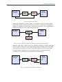
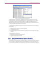
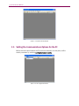
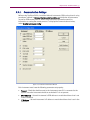
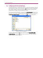
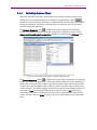
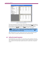
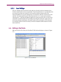
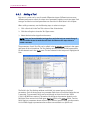
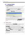
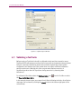
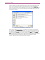
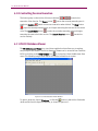
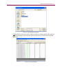
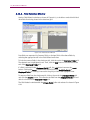
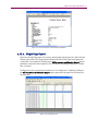
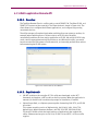
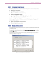
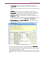
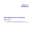
Chapter Four: Advanced Features | 49
4.3.1.
Loss Settings
The Loss Settings grid is provided so that the loss from the isolation chamber to the
Terminal antenna port can be characterized. The Primary Antenna Loss grid displays the
loss values from the end of cable C2 to the mobile’s primary antenna port. The
Secondary Antenna Loss grid displays the loss values from the end of cable C24 to the
mobile’s secondary antenna port. Secondary antenna loss is only used by receiver
diversity tests. To achieve the highest degree of accuracy possible, this loss should be
measured at several frequencies and entered into the grid. If the test system does not
include any Spirent instruments, (Channel Emulator, Noise Emulator or TCU) then the
loss settings should include all cables/connectors between the Base Station and the
Access terminal.
4.4. Editing a Test Suite
After you load the Test Suite, the TestDrive EV-DO window displays as shown in Figure
4-2.
Figure 4-2: Test Suite Window