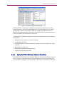
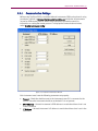
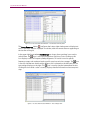
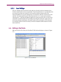
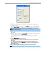
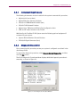
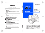
Download EV-DO-ATS - Spirent Knowledge Base

Transcript
EV-DO-ATS
EV-DO Automatic Test System
User Manual
Spirent
541 Industrial Way West
Eatontown, NJ 07724 USA
Email: [email protected]
Web: http://www.spirent.com
AMERICAS 1-800-SPIRENT • +1-818-676-2683 • [email protected]
EUROPE AND THE MIDDLE EAST +44 (0) 1293 767979 • [email protected]
ASIA AND THE PACIFIC +86-10-8518-2539 • [email protected]
This manual applies to EV-DO-ATS Version 5.10 or higher.
Page Part Number: 71-005930, Version A11
Copyright © 2012 Spirent. All Rights Reserved.
All of the company names and/or brand names and/or product names referred to in this document, in particular, the
name “Spirent” and its logo device, are either registered trademarks or trademarks of Spirent plc and its
subsidiaries, pending registration in accordance with relevant national laws. All other registered trademarks or
trademarks are the property of their respective owners.
The information contained in this document is subject to change without notice and does not represent a
commitment on the part of Spirent. The information in this document is believed to be accurate and reliable;
however, Spirent assumes no responsibility or liability for any errors or inaccuracies that may appear in the
document.
Table of Contents
1. Introduction .......................................................................................... 1
1.1.
Overview ........................................................................................... 1
1.1.1. Product Highlights .................................................................................. 1
1.1.2. EV-DO ATS Applications........................................................................... 2
1.2.
Theory of Operation ........................................................................... 3
1.2.1. Base Station to Access Terminal Network Model ...................................... 3
1.2.2. EV-DO ATS Network Model ...................................................................... 4
1.3.
Version History .................................................................................. 6
2. System Overview................................................................................. 24
2.1.
Overview ......................................................................................... 24
2.2.
Guided Tour ..................................................................................... 24
2.2.1. TestDrive EV-DO Automatic Test Executive ............................................. 24
2.2.2. Spirent SR5500 Wireless Channel Emulation......................................... 25
2.2.3. Spirent TAS5048 and SR5068 Test Configuration Units ......................... 26
2.2.4. SR8048 and SR8068 Test Configuration Units ...................................... 27
2.2.5. Base Station Emulator .......................................................................... 27
2.2.6. Spectrum Analyzer ............................................................................... 28
2.2.7. Vector Signal Generator (Two Units Required) ....................................... 29
2.2.8. Air Access Protocol Test System ............................................................ 29
2.3.
Installing EV-DO ATS Software .......................................................... 30
2.3.1. TestKit 5500 .......................................................................................... 30
2.3.2. TestDrive EV-DO Test Executive ..............................................................31
2.3.3. EV-DO ATS User and Reference Manuals ............................................... 32
2.3.4. Copy Protection .................................................................................... 32
2.4.
Rack Assembly................................................................................. 32
3. TestDrive EV-DO .................................................................................. 33
3.1.
Overview ......................................................................................... 33
3.2.
Starting TestDrive EV-DO .................................................................. 33
3.3.
Setting the Communications Options for the PC ................................ 34
3.3.1. Communication Settings ....................................................................... 35
ii | EV-DO-ATS User Manual
3.4.
Configuring the Terminal Settings..................................................... 38
3.5.
Loading a Pre-defined Test Suite ...................................................... 39
3.6.
Running a Test Suite ........................................................................ 42
3.6.1. Test Result Options ............................................................................... 42
3.6.2. Run-Specific Information ...................................................................... 42
3.6.3. Switching Between Views ..................................................................... 43
3.6.4. Halting Test Execution .......................................................................... 45
3.6.5. Viewing Test Results ............................................................................. 45
3.6.6. Generating a Report ............................................................................. 46
4. Advanced Features .............................................................................. 47
4.1.
4.2.
Overview ......................................................................................... 47
Editing a Terminal File ...................................................................... 47
4.3.
Setting Terminal Parameters ............................................................ 48
4.3.1. Loss Settings ........................................................................................ 49
4.4.
Editing a Test Suite .......................................................................... 49
4.4.1. Adding a Test ........................................................................................ 50
4.4.2. Group Edit ............................................................................................ 52
4.4.3. Parameter Sweep ................................................................................. 52
4.5.
System Calibration........................................................................... 53
4.5.1. Performing a Calibration ....................................................................... 54
4.6.
Software Options ............................................................................. 54
4.7.
Validating a Test Suite ..................................................................... 56
4.8.
4.9.
Working with Sessions ..................................................................... 57
Validating and Running a Session .................................................... 60
4.10. Controlling Session Execution ......................................................... 62
4.11. EV-DO Database Viewer .................................................................. 62
4.11.1. Database Viewer Toolbars ................................................................... 64
4.11.2. Field Selection Window........................................................................ 66
4.11.3. Common Fields vs. Unique Fields ......................................................... 67
4.11.4. Report Restrictions .............................................................................. 67
4.11.5. Software Options ................................................................................. 68
4.11.6. Customizing Reports with a Company Name and Logo ......................... 69
4.12. Report Types .................................................................................. 69
4.12.1. Report Type Selection Window ............................................................. 69
Table of Contents | iii
4.12.2. Selected Fields Report ......................................................................... 69
4.12.3. All Parameters and Results Report....................................................... 70
4.12.4. Single Page Report .............................................................................. 71
4.13. Security Features ............................................................................ 72
4.13.1. Entering a Password............................................................................ 72
4.14. TestDrive EV-DO API ........................................................................ 73
4.14.1. API Properties ..................................................................................... 73
4.14.2. API Methods ........................................................................................75
4.14.3. API Events ........................................................................................... 78
4.15. Multi-application Remote API .......................................................... 79
4.15.1. Overview ............................................................................................. 79
4.15.2. Requirements ..................................................................................... 79
4.15.3. Features and General Usage................................................................ 80
4.16. Email Notification ........................................................................... 82
4.16.1. Overview ............................................................................................. 82
4.16.2. Requirements ..................................................................................... 83
5. Troubleshooting EV-DO ATS ................................................................ 84
5.1.
5.2.
Overview ......................................................................................... 84
System Diagnostics ......................................................................... 84
5.2.1. Instrument Requirements ...................................................................... 85
5.2.2. Diagnostic Procedures .......................................................................... 85
5.2.3. Diagnostic Debugger ............................................................................ 88
5.3.
Test Validation Errors ....................................................................... 90
5.4.
Test Execution Errors ........................................................................ 91
5.4.1. Terminal Fails to Open a Session and or Setup Data Connections........... 91
5.4.2. Impairments Too Severe for Data Connection ........................................ 93
5.5.
Unexpected Results ......................................................................... 93
5.6.
Frequently Asked Questions ............................................................. 94
1. Introduction
1.1. Overview
The EV-DO Automatic Test System (EV-DO ATS) provides an integrated test solution for
evaluating parametric performance of EV-DO Access Terminals. The EV-DO ATS consists
of an SR5500 Wireless Channel Emulator, one to three Agilent 8960 Base Station
Emulator (S) , two AirAccess 3452 units, one 3462, two Agilent ESCs, and essential
CDMA test equipment.
TestDrive EV-DO software automates EV-DO testing by configuring the instruments,
stepping through the test sequences, and logging the results. By making most of the test
setup and configuration automated, EV-DO ATS solves the following testing issues:
•
Choosing the correct instruments and necessary system hardware.
•
Translating the test standards into instrument settings.
•
Writing software to automate test sequences.
•
Logging test results.
•
Reproducing test setups.
EV-DO ATS allows wireless service providers and equipment manufacturers and
developers to evaluate Wireless Data Access products relative to industry-standard test
requirements and user-defined test conditions.
1.1.1.
Product Highlights
EV-DO ATS meets and exceeds industry standards for EV-DO testing.
EV-DO test specifications require the performance of EV-DO Terminals be evaluated over
a variety of propagation and interference environments. To perform these tests, a system
that emulates the essential propagation and interference conditions is required. In
addition, these test beds require additional functions such as system control and
configuration, RF power measurement, and level control.
EV-DO ATS combines all elements required for these tests into one integrated system for
3GPP2 C.S0033 Rev B (TIA-866) AT-MPS tests, as well as TIA-866 based receive diversity
tests. When controlled by TestDrive EV-DO, the EV-DO ATS automatically executes these
Access Terminal tests and logs test results.
2 | EV-DO ATS User Manual
TestDrive EV-DO provides the ability to begin running automatic performance tests
in a matter of minutes.
TestDrive EV-DO provides an easy-to-use graphical user interface for automating Data
Access Terminal tests. Pre-defined tests taken from industry standards can be loaded
and running in minutes. This comprehensive software also facilitates creation of custom
test conditions to find the performance limits of the device under test. Whether running
pre-defined or custom tests, all results are logged in a Microsoft Access database. The
EV-DO built-in results viewer allows you to view and print results in a variety of standard
formats.
EV-DO ATS is based on advanced Spirent Communications emulation instruments.
Every EV-DO ATS includes the Spirent Wireless Channel Emulator (SR5500) with AWGN,
and the TAS5048 and SR5068 Test Configuration Unit (TCU). These instruments provide
the most integrated and powerful solutions available for evaluating Data Access
Terminal receiver performance.
The Spirent Wireless Channel Emulator implements a superset of all RF channel
conditions required for AT-MPS standard receiver testing, such as multi-path fading,
delay spread, and path loss as well as Additive Gaussian White Noise (AWGN). Dynamic
3GPDP channel models characterize rake receiver performance.
The TAS5048 and SR5068 Test Configuration Units are controlled by TestDrive EV-DO to
automatically select from a list of pre-defined test configurations. For systems integrated
with the Spirent LTE test solutions, the SR8048 and SR8068 are also supported. These
instruments eliminate the need to manually configure the system, optimizing test
execution speed.
1.1.2.
EV-DO ATS Applications
EV-DO ATS yields thorough testing of EV-DO devices in a laboratory setting. This gives
accurate and repeatable test results, allowing you to detect, isolate, and correct
performance problems in the shortest possible time. EV-DO ATS eliminates the need for
expensive, labor-intensive test systems and can drastically reduce the time spent doing
field tests whose conditions cannot be controlled or repeated. Applications for EV-DO
ATS include:
•
Product Development
•
Design Verification
•
Product Qualification
•
Conformance Test
•
Competitive Analysis
•
Performance Analysis
Chapter One: Introduction | 3
1.2. Theory of Operation
EV-DO ATS is a complete, integrated system for evaluating the performance of EV-DO
Access Terminals. This system includes all the test instruments and control software
required to accurately emulate the bi-directional end-to-end connection between the
base station emulator and access terminal under test. An overview of the network model
is shown in Figure 1-1.
1.2.1.
Base Station to Access Terminal Network Model
The Base Station – Access Terminal connection is an RF link as shown below. The Base
Station to Access Terminal link is considered the Forward Channel. Conversely, the
Access Terminal to Base Station link is termed the Reverse Channel. The Forward and
Reverse Channels operate at independent carrier frequencies. They transport data, and
signaling information between the Base Station and Access Terminal by means of a
spread spectrum carrier.
AWGN
Generator
Ioc
Base Station
Tx
Rx
Access Terminal
Ior
Channel
Simulator
Ior
Io
Rx/Tx
Figure 1-1: Access Terminal - Base Station Network Model
for Demodulation of the Forward Channel with Fading and Noise
Typically, when assessing the performance of access terminals, the Forward Channel is
impaired while the Reverse Channel is left uncorrupted. This is done in order to evaluate
the access terminal’s ability to demodulate the transmit signal from the base station
under adverse conditions. Industry standards require the access terminal to be
characterized under the influence of multi-path propagation effects as well as additive
co-channel and adjacent channel interference. Co-channel interference is approximated
by Additive White Gaussian Noise (AWGN) while Continuous Waveform (CW) signals are
utilized to act as adjacent channel interferers.
Test standards define typical propagation channel models which range from one to three
paths. Each path undergoes Rayleigh fading and, for models with multiple paths, relative
path-to-path delay and attenuation are also specified. A typical test model involving
fading is shown in Figure 1-1.
4 | EV-DO ATS User Manual
Due to frequency re-use requirements, signals transmitted in nearby cells propagate
beyond their own cell boundaries and interfere with the signal reception in bordering
cells resulting in co-channel interference. To emulate these interference conditions, test
standards require various levels of AWGN be combined with the transmitted signal to
approximate the interference created by users in other cells. To test the selectivity of the
access terminal, tests are specified to simulate users operating at carrier frequencies
adjacent to the channel of the Terminal under test. This is accomplished by summing
single or dual CW signals with the Base Station transmit signal to act as adjacent
channel interferers. A typical test model involving co-channel or adjacent channel
interference is shown in Figure 1-2.
AWGN
Generator
Ioc
CW
Generator
Tone
Power
Base Station
Tx
Access Terminal
Ior
Rx
Io
Rx/Tx
Figure 1-2: Access Terminal - Base Station Network Model for Demodulation
of Forward Channel with co-Channel or Adjacent Channel Interference
1.2.2.
EV-DO ATS Network Model
Meeting the specifications of the Access Terminal-Base Station Network Model
discussed above requires sophisticated instruments capable of emulating the test
environments in an accurate and repeatable manner. To be truly beneficial, these
instruments must also be capable of emulating conditions beyond the minimum
requirements defined by the industry test standards. By providing a broader range of test
conditions, the system can find the performance limits of the access terminal under test.
EV-DO ATS allows for three main configurations of the Access Terminal-Base Station
Link. This is made possible with the TAS5048 and SR5068, or SR8048 and optional
SR8068 Test Configuration Units. . One or two auxiliary Base Station emulators may be
added for EV-DO Rev B. Multicarrier Tests. The multiple basestation emulators are
connected by a three-to-one combiner. The first configuration, shown in Figure 1-3,
utilizes the SR5500 Wireless Channel Emulator in the forward path to provide
impairments. In addition, a Base Station Emulator provides all the signaling and
communication protocols necessary to initiate data connections as well as evaluate the
Packet Error Rate (PER) performance of the access terminal
Chapter One: Introduction | 5
Base Station
Emulator
SR5500
Access
Terminal
SR5068
Rx/Tx
Figure 1-3: EV-DO ATS Test System
The second configuration, shown in Figure 1-4, provides a direct connection from the
Base Station Emulator to the Access Terminal under test, shown below. The spectrum
analyzer is available to measure Access Terminal transmit signals. This configuration is
particularly useful for Access Terminal transmitter tests.
Base Station
Emulator
Access
Terminal
Power
Divider
Rx/Tx
Spectrum
Analyzer
Figure 1-4: Direct Configuration of Base Station Emulator and Access Terminal Under Test
The third configuration, shown in Figure 1-5, utilizes the SR5500 to split the signal from
the base station emulator into two independently impaired forward paths. These paths
are connected to the primary and secondary receive antennae on the mobile station.
The reverse path is unimpaired and is transmitted solely on the primary antenna
connection. This configuration is used for Receiver Diversity tests.
Base Station
Emulator
Access
Terminal
SR5500
SR5068
Rx/Tx
Rx
Figure 1-5: EV-DO ATS Receive Diversity Configuration
6 | EV-DO ATS User Manual
1.3. Version History
This version history highlights features and enhancements to EV-DO ATS since the first
version of the product.
Version 5.10
•
Added support for C.S0033 Revision C. This includes new modulated interferers for
Test cases 3.3.2 and 3.3.3. All supported test cases have been updated to conform
to this new standard revision. In addition, new standard suites pertaining to this
revision of the specification have been created.
•
Added support for 10 MHz and 5 Mhz LTE Interferers. This is required by some carrier
acceptance test plans.
•
Added support multi carrier test cases on the systems that include the SR8048 and
SR8068 TCUs.
•
Added support for a third Agilent 8960 when running multi carrier test cases. This
allows you to execute three carrier test cases specified in the C.S033 standard.
The following maintenance updates have been added in the 5.10 release of TestDrive
EV-DO:
•
Corrected an issue with Trial passwords. Software features were not properly being
enabled with Trial passwords.
•
When running Idle Handoff in continuous operation mode or Forward Traffic Demod
during soft handoff tests on system with SR8048 TCUs, you may encounter a level
out of range error. This has been corrected.
•
Corrected an error handling issue in Access Probe output power and Range of Open
Loop power test cases.
Version 5.00
•
Added Support for new TCUs; SR8048 and SR8068. This allows you to perform EV-DO
and LTE testing on the same system without re-cabling the instruments used across
test themes.
Version 4.70
•
Added a reduced system configuration for automatically executing following test
cases with the minimum ATS instrument (Agilent 8960 Base Station Emulator,
Spectrum Analyzer, and SR5048).
3.1.2.4.1 Conducted Spurious Emissions.STE
3.3.1 Receiver Sensitivity and Dynamic Range.STE
4.1.2 Frequency Accuracy.STE
4.2.2 Waveform Quality and Frequency Accuracy.STE
4.3.1 Range of Open Loop Output Power.STE
4.3.3 Range of Closed Loop Power Control.STE
4.3.4 Maximum RF Output Power (Inside Japan).STE
4.3.5 Minimum Controlled Output Power.STE
Chapter One: Introduction | 7
•
Modified following test cases to run using the physical layer Sub Type 3 (MCTAP) for
the Rev. B tests as defined in C.S0033-B v1.0 (dated May 12, 2008).
3.2.1 Demodulation of Forward Traffic Channel in AWGN
3.2.2 Single Tone Desensitization
3.3.1 Receiver Sensitivity and Dynamic Range.STE
3.3.2 Single Tone Desensitization
4.3.1 Range of Open Loop Output Power.STE
4.2.2 Waveform Quality and Frequency Accuracy.STE
4.3.4 Maximum RF Output Power (Inside Japan).STE
4.4.1 Conducted Spurious Emissions.STE
•
Modified Instrumentation menu selection to run multi carrier EV-DO Rev B. tests.
•
Modified database for the test case shown above to display the Rev. B test results.
Version 4.60
•
Added C.S0033-A test 3.3.4 Adjacent Channel Selectivity. This is a Band Class 6 only
test. It is similar to the existing Single Tone tests for other band classes but instead
uses a modulated interference. NOTE: To run this test, ESG 1 must be equipped with
Options 602 - Internal Baseband Generator.
•
Reduced the path loss for the Receiver Sensitivity and Dynamic Range test (C.S00330 test 3.1.1.3.1 / C.S0033-A test 3.3.1) and the Minimum Controlled Output Power
test (C.S0033-0 test 3.1.2.3.5 / C.S0033-A test 4.3.5). These tests are run at a high
Ior value and the levels’ budgeting is very tight; it limits the acceptable loss between
the Spirent system and the Mobile. These test cases have been modified to use a
different path in the TCU which contains about 6 dB less loss. This allows some
flexibility with regards to what cabling and devices you can put between the mobile
antenna and the Spirent Equipment.
•
Added a Delay before test parameter for all 3462 based tests. Due to an issue with
some handsets, it is necessary to wait some period of time after a reset before
starting a test. If this wait is not done the phone completes the reset after returning
from the reset command and drops a call. The reset is done as part of session
management with Air Access and the phone. 8960-based tests do not have this
problem; as it is not necessary to reset the phone before each test.
•
Added Support for new Agilent 8960 hardware version “5.8”, as well as the
corresponding E6706B lab application version. The older hardware/software
(E6706A/E1966A) application versions will continue to be supported.
•
Made a minor enhancement to the Password protection feature. In the Suite window,
the Text Description and Override Channel text boxes could be selected but not
edited. These controls were modified so that they cannot be selected like other
controls when password-protection is enabled.
•
Added a feature to send a test message when configuring the Email notification
interface. This feature allows you to verify that the Email notification is set properly
without having to run a test suite.
8 | EV-DO ATS User Manual
•
Made some minor enhancements to the Diagnostic Debugging utility user interface.
The enhancements clarified instructions and made it easier to navigate though
debugging sequences.
The following maintenance updates have been added in the 4.50 release of TestDrive
EV-DO:
•
Corrected an issue that occurred when attempting to copy the intermediate results
window. Clicking a “CTRL+C” combination was popping up error box saying “Error
#438 (Object doesn’t support this property or method).”
•
Corrected an issue where it was possible to pass the Standby Output Power test
even if no probes were detected during the system access state. Since the test is
attempting to measure the power between probes, if the phone fails to sent access
probes the test will be undetermined instead of a pass.
•
Corrected and issue with Hard Handoff to Another Frequency test (C.S0033-0 test
6.1.1.2.4 / C.S0033-A test 6.6). When attempting to run this test for BC15 (AWS),
BC6 (IMT2000) was getting set instead.
•
Corrected an issue with several Soft Handoff test cases. The Traffic channel
assignment message was not setting the proper value to specify soft vs softer
handoff. Tests Effected by this issue are:

3.2.3 Decision of Power Control Bit for Channels belonging to Different
Power Control Sets during Soft Handoff

3.2.4 Decision of Power Control Bit for Channels belonging to the Same
Power Control Set

3.2.5 Demodulation of Reverse Power Control Channel during Soft Handoff.

6.1 Idle Handoff in Continuous Operation Mode

6.2 Idle Handoff in Slotted Operation Mode

6.3 Neighbor Set Pilot Detection and Incorrect Detection in Soft Handoff

6.4 Candidate Set Pilot Detection and Incorrect Detection in Soft Handoff

6.5 Active Set Pilot Loss Detection in Soft Handoff
•
Corrected an issue with Idle Handoff in Continuous Operation mode and Idle Handoff
in Slotted Operation mode tests (C.S0033-0 tests 6.1.1.1.1, 6.1.1.1.2 / C.S0033-A
tests 6.1, 6.2) Neighbor Count setting in Sector Parameter message was being
incorrectly set to 0 causing the mobile to think there are no neighbors. This has been
corrected.
•
Corrected an issue with C.S0033-A test 5.3 Demodulation of Forward Traffic Channel
during Soft Handoff. Test intermittently reported error retrieving FTAP parameters.
•
It was observed that from time to time when an 8960 based test cases are running
after an Air Access Test case the mobile appeared to be able to still see the Air
Access Signal. This is likely an over the air leakage issue that would not occur if the
mobile is in an isolation chamber. In order to ovoid the possibility of this problem
occurring, after all air access based tests are completed call processing is turned off
in Air Access
Chapter One: Introduction | 9
•
Active Set Pilot Loss Detection in Soft Handoff test (C.S0033-0 test 6.1.1.2.3 /
C.S0033-A test 6.5) was sending the wrong PN value in the Traffic Channel
Assignment message. This has been Corrected.
•
There was an error in the State 2 Ior value reported in the intermediate results
window of the Candidate Set Pilot Detection and Incorrect Detection in Soft Handoff
test (C.S0033-0 test 6.1.1.2.2 / C.S0033-A test 6.4). The test was actually setting the
right values but displaying the wrong value. This has been corrected.
Version 4.50
•
TestDrive EV-DO no longer supports older TAS3460 AirAccess Instruments. The only
supported Air Access hardware is now SR3452 V2s and SR3462.
•
The following 3GPP2 C.S0033-0 and C.S0033-A tests have been modified to use the
SR5500 to change levels during the course of test execution. This allows finer level
resolution than the Air Access allowed in the previous implementation of these test
cases. As a result the levels now conform exactly to the values listed in the testing
standards.
C.S0033-0
Test #
C.S0033-A
Test #
Title
3.1.1.2.5
3.2.5
Demodulation of Reverse Power Control Channel During Soft Handoff
6.1.1.1.1
6.1
Idle Handoff in Continuous Operation mode
6.1.1.1.2
6.2
Idle Handoff in Slotted Operation mode
6.1.1.2.1
6.3
Neighbor Set Pilot Detection and Incorrect Detection in Soft Handoff
6.1.1.2.2
6.4
Candidate Set Pilot Detection and Incorrect Detection in Soft Handoff
6.1.1.2.3
6.5
Active Set Pilot Loss Detection in Soft Handoff
•
Added intermediate results for the Conducted Spurious Emissions test (C.S0033-0
test 3.1.2.4.1 / C.S0033-A test 3.4.1). Intermediate Results are now displayed for the
Spurious Emissions test in the Test Results panel. This gives you more visibility into
steps performed during test execution. It will also allow you to see how the device
under test is performing while the test is executing, rather than having to wait until
the suite is complete.
•
Added Intermediate results for the Maximum RF Output Power test (C.S0033-0 test
3.1.2.3.4 / C.S0033-A test 4.3.4). Intermediate Results are now displayed for the
max power test in the Test Results panel. This gives you more visibility into the test
steps as it is being executed.
•
The Session User Interface has been enhanced, allowing you to view terminal files
and suite files directly from the session grid. Clicking the session grid still launches a
file menu that points to a terminal file or suite file. The key sequence CTRL+click now
displays the relevant suite file or terminal file.
•
A diagnostics debugging tool has been added to the TestDrive EV-DO installation.
This tool is installed to the “utilities” subfolder under the directory the TestDrive EVDO application is installed in (the default location is C:\Program
Files\TestDrive\EV-DO\Utilities). If the diagnostic procedure reports a failure, this
tool leads you through a set of measurements to determine the cause of the
diagnostic failure. Typically, when a diagnostic failure occurs, TestDrive EV-DO
software instructs you to confirm that cables are connected properly and each unit is
10 | EV-DO ATS User Manual
powered-on correctly, but does not offer any additional assistance if everything is
cabled properly and powered-on. The diagnostic debugging tool helps narrow down
the exact cause of the failure in the event it is something more complex than a
cabling error.
•
TestDrive EV-DO has been modified to clearly indicate when there is a mismatch
between the SR5500 instruments firmware and the API on the controller PC. Previous
versions of TestDrive software would only indicate that there was an API error but not
indicate the cause of the error. Error handling has been enhanced to clearly indicate
when a Firmware mismatch occurs.
•
Changed the default selection of parameters when characterizing mobile
automation. The default set of automation features to characterize was none. This
required you to select each of the parameters they want to characterize before
running characterization. The typical usage of this feature is to characterize all
available automation features unless attempting to access an unsupported feature
causes a problem with the phone that would affect subsequent supported
parameters. TestDrive EV-DO has been modified to have all parameters selected by
default instead of none.
•
Added the ability to set power step size for C.S0033A test 4.3.4 Maximum RF Output
Power Test. This is a user settable parameter. Standard test suites still default to 1
dB but can be modified by users in order to test smaller step sizes.
•
Enhanced results reporting for C.S0033A test 4.3.8.3 Data Channel Output Power.
The Rev A version of this test has a variety of requirements that are validated as part
of the test case. When this test fails the software was not providing sufficient data to
easily determine the cause of the failure. This test has been modified to report a
clear fail reason along with any test failures that occur.
•
Increased the Maximum # of tests allowed in a suite. Previously the max number of
rows was 255. The allowable number of rows has been doubled to 510.
•
Added support for band class 10 for 8960 based test cases. Air Access does not
support band class 10 so Test Pack 3 test cases cannot be run, but all test that use
the 8960 Base Station Emulator can be executed for band class 10.
•
Password protection of suits and sessions feature has been modified to no longer
show a pop up window every time the TestDrive EV-DO software loads. Instead, you
must go into software options to enable and disable this feature. When password
protection is enabled TestDrive will launch in read only mode by default and anyone
wishing to modify suites will have to disable read only mode by entering the correct
password in the software options menu. In addition it was observed that in the rare
event TestDrive software crashed or windows crashed after a new password was
entered it was not being saved. The password protection feature has been modified
to save the password as soon as it is entered rather than when the software is closed
so that it is saved regardless how the software terminates.
•
Modified the channel over ride feature available in the suite grid so it is less
confusing. Previously the over ride channel only applied to tests executing in
connected state and would be ignored for other test cases performed without a data
connection established. For example idle handoff tests or access probe tests would
ignore the over ride channel and instead execute on the channel number specified in
the terminal file. Now when an over ride channel is specified it will be used
Chapter One: Introduction | 11
regardless of the test type. It is assumed that the channel is in the phones PRL for all
non-connect state tests and all test cases that use the SR3462 EV-DO network
emulator.
•
Added e-mail notification feature for test execution events in TestDrive EV-DO.
TestDrive software can be set up to send a notification email when suit execution
starts, when it ends, if a fatal error occurs or if a specified number of undetermined
test results occur.
The following maintenance updates have been added in the 4.40 release of TestDrive
EV-DO:
•
The displayed Eb/Nt was not correct for tests where FETAP was used. In some test
cases, when FETAP was selected, FTAP parameters (data rate) were being used to
calculate Eb/Nt. Parameters were being set up correctly in accordance to the test
standards but value for Eb/Nt was being displayed incorrectly.
•
For C.S0033A Test 5.5 Access Probes Output Power the sector ID used for the test did
not match what was set in the terminal file. This has been corrected.
•
For C.S0033A test 6.5 Active Set Pilot Loss Detection in Soft Handoff the wrong PN
value that was being sent in the traffic assignment message. This has been
corrected.
•
For the "retry failed and undetermined test results" feature, the number of retries was
not accurate when there was a mix of retests for undetermined and failed test
results. This feature has been modified so that a single number of retries is settable.
The TestDrive software will stop when the sum of failed and undetermined tests
totals the set value.
•
Corrected a possible loop gain issue. Under certain conditions it was possible to
have loop gain in the RF signal path for some diversity test cases. This is not the case
for all systems but could happen for systems with lower than average loss
components and a higher than average amplifier in the TCU. The software has been
modified to enable a TCU attenuator to avoid loop gain in paths it could have
possibly occurred.
•
Corrected a reverse loss setting error. This issue occurred for some diversity test
cases only during data connection setup. The symptom of this issue is tests need
several re-tries to setup a data connection when the setup channel number differs
from the test channel number. In some instances the connection would not get setup
and would result in undetermined test results. This issue has been corrected.
•
Incorrect error reported when TestDrive was characterizing mobile automation. When
characterizing NV item SCPStatus, and this item failed, TestDrive EV-DO reported an
error message containing the wrong parameter name. This has been corrected.
•
C.S0033A test 4.3.4 Maximum RF Output Power Test was using the downlink
frequency for retrieving the uplink and downlink calibration values. Since the RF path
for this test varies slightly over frequency the actual error in loss value was very
minimal for most band classes. For Band Class 5 uplink and downlink frequencies
are further apart resulting in a detectable error in test performance. This error been
corrected.
12 | EV-DO ATS User Manual
•
The last suite of a session was not getting saved properly. If a user loaded a session
then swapped the last suite in that session and saved the session, the swapped
suite was not getting saved. This has been corrected.
•
Channel Output Power test (C.S0033-A test 4.3.7, 4.4.8.1, 4.4.8.2, and 4.4.8.3) have
been enhanced to allow users to more easily and accurately characterize a mobile’s
channel output power requirements. The way averaging is set has been changed.
There are two parameters associated with setting multiple measurements for this
test. “Number of averages per measurement” indicates how many samples are used
in calculating the average Code Channel power. The “number of measurements”
parameter allows you to perform multiple measurements of the specified number of
averages. When setting number of measurements to a value greater than 1 the test
will report a fail if any of the specified number of measurements fails. In addition,
the “RRI Gain” field has been changed to “RRIChannelGainPreTransition3” to clearly
identify the parameter.
•
C.S0033A test 4.3.8.3 Subtype 2 Test 5 was not setting the Aux gain to 3.5 dB as per
the testing standard. This issue has been corrected.
•
An issue was observed with multiple commercial handsets for Pilot Detect tests
C.S0033A 6.3-6.5. The mobiles where dropping the call before the test was
complete. It was determined that this was an issue resulting from the mobile being
remotely reset and returning from the reset command before the mobile was
completely reset. At some period after the reset command if a connection was active
the mobile would drop the connection upon the actually completing the reset
process. A “delay before test” parameter was added to the user interface. When
testing a mobile whose device driver returns prematurely from a reset command, you
should set the delay before test parameter to a value that ensures the mobile has
completed a reset before the test starts.
•
C.S0033A 4.3.2 Time Response of Open loop test was using the wrong data rate or
sub type 2 test cases. This has been corrected.
•
C.S0033A 6.4 Candidate Set Pilot Detection and Incorrect Detection in Soft Handoff,
the location in the test sequence where the reset report is sent to the mobile has
been changed. This is not defined in the testing standard but Qualcomm indicated
that this message should be sent to the mobile immediately after state 1 levels are
set in order to ensure the correct rout update message is analyzed.
•
C.S0033A Test 6.1 Idle Handoff in Continuous Operation mode and Test 6.2 Idle
Handoff in Slotted Operation mode intermittently were not terminating the data
connection properly. Both tests are done in idle state but open a data connection to
retrieve parameters. Intermittently an error could occur when ending the data
connection causing the mobile to not return to idle state in order to continue the test.
This has been corrected.
•
C.S0033A test 4.3.4 Maximum output power for Band Class 5 the limits for Power
Class 3 and 4 were interchanged in some of the Standard Test Suites. This has been
corrected.
•
C.S0033A test 3.2.3 Decision of Power Control Bit for Channel Different Set Sub Type
0 test suites appeared in the Sub Type 2 folder. The individual chapter suites for this
test case were incorrect for sub type 2. This has been corrected. The “All Subtype 2
Chapter One: Introduction | 13
Tests (8960 based).STE” suite file did not contain this bug, only the individual
chapter suite.
•
For maximum output power tests and receiver sensitivity tests the spectrum analyzer
is in the return path of the mobile’s transmit signal but the spectrum analyzer is not
used to make any measurements as part of the test sequence. In these cases the
spectrum analyzer is not set up to perform any measurements but is still receiving a
very strong signal from the mobile and may be over driven. It was observed that over
driving the spectrum analyzer could result in cross modulation products showing up
in the receive band of the mobile and can effect test performance. Both test cases
have been modified to set the spectrum analyzer’s input attenuator to stop
overloads from occurring.
Version 4.40
•
•
The following tests have been modified to run using physical layer Sub Type 2 (ETAP)
in accordance with TIA-866-A/ C.S0033-A v1.0:

3.1.1.2.5 Demodulation of Reverse Power Control Channel During Soft Handoff

3.2.3 Decision of Power Control Bit for Channels Belonging to Different Power
Control Sets During Soft Handoff

3.2.4 Decision of Power Control Bit for Channels Belonging to the Same Power
Control Set

3.2.5 Demodulation of Reverse Power Control Channel During Soft Handoff

5.2 Data Rate Control Performance

5.3 Demodulation of Forward Traffic Channel during Soft Handoff

5.4 Supervision Procedures in Variable Rate State

5.6 Reverse Traffic Channel Initial Transmit Power

6.1 Idle Handoff in Continuous Operation mode

6.2 Idle Handoff in Slotted Operation mode

6.3 Neighbor Set Pilot Detection and Incorrect Detection in Soft Handoff

6.4 Candidate Set Pilot Detection and Incorrect Detection in Soft Handoff

6.5 Active Set Pilot Loss Detection in Soft Handoff

6.6 Hard Handoff to Another Frequency
The following test has been modified to run using physical layer Sub Type 2 (ETAP) in
accordance with the Qualcomm Application Note: Recommended Minimum
Performance for CDMA2000 1xEV-DO Revision A Rx Diversity-Capable Access
Terminals, 80-VF496-11 Rev. A, May 17, 2007. The Application Note details the EVDO Rev. A Mobile Receive Diversity test cases:

3.1.1.2.5 Demodulation of Reverse Power Control Channel During Soft Handoff
•
Added support for Band Class 14 and Band Class 15.
•
Added Support for Air Access version 3.10.
The following maintenance updates have been added in the 4.40 release of TestDrive
EV-DO:
14 | EV-DO ATS User Manual
•
IS 866A test 4.3.7 RRI Channel Output Power test was not setting RRI gain properly in
the 8960 this value was changed to something other than what is specified in the
testing standard. This has been corrected.
•
There was an issue handling certain call processing errors for test where the Call
Limit was set to on in the 8960. This has been corrected.
Version 4.30
The following enhancements have been added in the 4.30 release of TestDrive EV-DO:
•
Added TIA-866A/C.S0033A test 3.2.6 Demodulation of ARQ Channel.
•
Added the ability to remotely control TestDrive EV-DO over a socket connection or
through an API on the same PC. This allows you to run suites across different ATS
products. In addition, you can use a scripting language to control additional test
instruments or power supplies, and run ATS tests as part of a larger test script.
•
The following Test Drive EV-DO test cases have been modified to use averaging when
taking the code channel measurements. This results in consistent and stable test
results:
•

4.3.7
RRI Channel Output Power

4.3.8.1
DRC Channel Output Power

4.3.8.2
ACK Channel Output Power

4.3.8.3
Data Channel Output Power

4.3.8.4
DSC Channel Output Power
Added TIA-866A/C.S0033A test 3.2.6 Demodulation of ARQ Channel.
Chapter One: Introduction | 15
•
Added a rate of change measurement to C.S0033-A test 4.2.1 Time Reference.
Previously, Test Drive EV-DO measured only the static case.
The SR5500 is used to introduce a delay of the forward path. The mobile’s ability to
synchronize to that delay within the timing constraints in the testing standard is now
measured.
•
Added the ability to perform margin testing for packet error rate tests. TestDrive EVDO now supports margin testing for Receiver Sensitivity, Single Tone Desensitization
and Intermodulation Spurious Response.
Margin testing characterizes the mobile’s ability to perform beyond the limit
specified in the standards.
The impairment used in a given test is increased to determine how far beyond the
level specified in the standard the mobile can still operate at or below the specified
maximum packet error rate.
•
Enhanced results reports ensure clearly define what each test case is testing.
For some test cases, it was difficult to determine by viewing the results report what
standard the phone is being held to. This is common for tests that do not include
user-defined pass/fail limits.
TestDrive EV-DO reports were enhanced to ensure that all tests clearly define what
pass/fail criteria used, as well as the failure reason for failed tests.
•
Added limit lines to the results report for Time Response of Open Loop Power Control
tests (C.S0033 test 3.1.2.3.2 or C.S0033A test 4.3.2).
•
Enhancement communication logging feature to enable more efficient debugging of
issues.
The Communications Log now includes Test Description and Status. Any errors that
occur during test execution are now logged.
•
Enhanced code that interfaces to the UTS driver to make Test Drive EV-DO
compatible with the latest generic driver.
•
Added a feature to allow password protection of suite and session parameters. If this
feature is enabled, only entering the password will allow editing suite and session
settings.
The following maintenance updates have been added in the 4.30 release of TestDrive
EV-DO:
•
Corrected an issue with the fading profile for some of the subtests in C.S0033-A test
3.22 Demodulation of Forward Traffic Channel in Multi-path Fading Channel.
•
Corrected and issue with C.S0033-A test 4.4.1. The absolute emissions sweep was
wrong for close in spurs. Because the test specifies the “least stringent” of the
absolute and relative sweeps, most mobiles pass this test by passing the relative
sweeps. Observing the graphs showed an issue with the absolute sweeps. This has
been corrected.
•
C.S0033-A test 5.4 Supervision Procedures in variable rate state could get caught in
an endless loop, and not complete the test.
When triggering rate transitions, this test would loop waiting for a transition. If the
transition never occurred, it would not exit the loop. This issue has been corrected.
16 | EV-DO ATS User Manual
•
C.S0033-A test 4.3.3 Range of Closed loop power test had an issue capturing the
slope measurements for mobiles with have a significant delay between when the all
down power control bits are sent and when the mobile starts changing its output
power. This test has been modified to dynamically alter the delay before the
spectrum analyzer sweep begins.
•
For some mobiles, there was an issue triggering the second sweep for C.S0033-A
Test 5.5 Access Probe Output Power test. The video trigger value was set to low and
causing the spectrum analyzer trace to trigger too early. This has been corrected.
•
Corrected an issue with C.S0033-A test 3.2.3 Decision of Power Control Bits
(Different set) During Soft Handoff and test 3.2.4 Decision of Power Control Bits
(Same Set) During Soft Handoff.
AirAccess was lowering the mobile power level before starting the power control bit
pattern prescribed by the test specification. This could cause the lower part of the
mobile transmit power traces to occur in the noise floor of the spectrum analyzer, or
hit the lower power limit of the mobile. This test has been modified so the average
power (before the test’s power control bit pattern starts) is high enough to prevent
this issue.
Version 4.20
The following enhancements have been added in the 4.20 release of TestDrive EV-DO:
•
•
The following EV-DO Rev. A Mobile Receive Diversity test cases have been
implemented. These tests are specified by the Qualcomm Application Note, detailing
the EV-DO Rev. A Mobile Receive Diversity test cases:

3.2.1 Demodulation of Forward Traffic Channel in AWGN

3.2.2 Demodulation of Forward Traffic Channel in Multi-path Fading Channel

3.3.1 Receiver Sensitivity and Dynamic Range

3.3.2 Single Tone Desensitization

3.3.3 Intermodulation Spurious Response Attenuation
The following EV-DO Rev. 0 test cases were not meeting the levels requirement
specified in the test specification (TIA-866). The test cases have been enhanced to
achieve the specified test levels by using amplifies in the 5068:

3.1.1.2.5 Demodulation of Reverse Power Control Channel During Soft Handoff

6.1.1.1.1 Idle Handoff in Continuous Operation mode

6.1.1.1.2 Idle Handoff in Slotted Operation mode

6.1.1.2.1 Neighbor Set Pilot Detection and Incorrect Detection in Soft Handoff

6.1.1.2.3 Active Set Pilot Loss Detection in Soft Handoff
•
Added a feature to allow the running of Single Tone Desensitization, Receiver
Sensitivity with all up power control bits.
•
Added the ability to export results to PDF format. NOTE: This feature requires
software package called PDF995 be installed on the PC.
Chapter One: Introduction | 17
•
TestDrive EV-DO have been enhanced to provide an option automatically re-run tests
that result in “Undetermined” and/or “Fail” status. The re-run will occur immediately
following the failed or undetermined test status. You have the ability to select,
“Undetermined”, “Fail” or both be re-executed. The maximum number of times the
software will automatically retry a test is user-configurable. Note that the specified
number is the sum of both fail and undetermined test.
•
Modified some diagnostics error messages to better direct the customer to the cause
of the errors.
•
Added the ability to specify a Minimum Frame count for Packet Error Rate tests when
confidence testing is turned on in the 8960. This feature is important when running
fading tests to ensure the mobile is exposed to the full time varying fading profile
before truncating the test due to the confidence requirement being met.
•
Added support for Band Class 15 (AWS Band) for 8960 based test cases. TestDrive
EV-DO now enables you to test Band Class 15 access terminals for all tests except
those that use the SR3462.
•
Improved the timing accuracy of level variations for C.S0033A test 6.1 Idle Handoff in
Continuous Operation Mode and 5.3 Demodulation of Forward Traffic Channel during
Soft Handoff. The TestDrive EV-DO software was modified to make use of the DEE
feature in the SR5500 which provides highly accurate level cycling for the tests.
•
Added ability to track suite and session duration. TestDrive EV-DO already allowed
you to view how long individual tests took to execute. Now it is possible to view
execution duration totals for both suites and Sessions.
The following maintenance updates have been added in the 4.20 release of TestDrive
EV-DO:
•
Corrected issues with test duration fields. Several TestDrive EV-DO test cases had
missing or inaccurate test duration results. These have been fixed.
•
Candidate detect tests (C.S0033A tests 6.3-6.5) have been modified to more
accurately conform to the testing standard. Spirent received some clarifications from
Qualcomm regarding these test cases and has incorporated those into the TestDrive
EV-DO software. The changes primarily involve ensuring the pilots are in the proper
sets before disabling responses to rout update messages.
•
An issue was corrected where after a session is executed with all instruments being
marked as available in system, followed by a session in which only the Base Station
is marked as being present, suites were unable to run properly reporting “object with
block is not set”.
•
Corrected and issue when launching the help feature from the diagnostic window.
•
Corrected and error that occurred when attempting to generate a details report for
test 3.1.2.4.1 Conducted Spurious Emissions, when sorting on failed tests results
only.
•
In a recent TestDrive EV-DO release the ESN database field was replaced by the
Hardware ID field. In some cases the Hardware ID was not getting written properly for
some mobiles. This issue has been corrected.
•
Corrected the throughput calculations for several test that use variable data rate.
Calculations were incorrect because they were not taking into consideration the fact
18 | EV-DO ATS User Manual
that packet size may vary. Observed errors in calculations resulted in a lower than
expected throughput result.
Version 4.00
The following enhancements have been added in the 4.00 release of TestDrive EV-DO:
•
•
•
The following new TIA-866-0 test cases are now supported in TestDrive EV-DO.

3.1.1.2.3-Decision of Power Control Bit for Channels Belonging to Different Power
Control Sets During Soft Handoff

3.1.1.2.4-Decision of Power Control Bit for Channels Belonging to the Same
Power Control Set

3.1.1.2.5-Demodulation of Reverse Power Control Channel During Soft Handoff

4.2.1.1 -Data Rate Control Performance

4.2.1.2 -Demodulation of Forward Traffic Channel during Soft Handoff

4.2.1.3 -Supervision Procedures in Variable Rate State

4.3.1.1 -Access Probes Output Power

4.4.1.1-Reverse Traffic Channel Initial Transmit Power

4.4.1.4 -Reverse Traffic Channel MAC Rate Transition Probabilities

6.1.1.1.1 -Idle Handoff in Continuous Operation mode

6.1.1.1.2 -Idle Handoff in Slotted Operation mode

6.1.1.2.1 -Neighbor Set Pilot Detection and Incorrect Detection in Soft Handoff

6.1.1.2.2 -Candidate Set Pilot Detection and Incorrect Detection in Soft Handoff

6.1.1.2.3 -Active Set Pilot Loss Detection in Soft Handoff

6.1.1.2.4 -Hard Handoff to Another Frequency
The following 80-V8941-1 Rev. C test is now supported in TestDrive EV-DO

3.7 FTC MAC Protocol: Data Rate Control Performance

Added Support for the following 8960 Application versions:

E1966A EV-DO Test Application Version: A.06.10

E1966A EV-DO Lab Application Version:
A.03.10
The following tests have been enhanced to conform to C.S0033 Rev A. Most of the
enhancements pertain to support for testing Subtype 2 Physical Layer and additional
channels such as DSC. The following is a comprehensive list of tests :

3.1 -Frequency Coverage Requirements

3.2.1 -Demodulation of Forward Traffic Channel in AWGN

3.2.2 -Demodulation of Forward Traffic Channel in Multi-path Fading Channel

3.3.1 -Receiver Sensitivity and Dynamic Range

3.3.2 -Single Tone Desensitization

3.3.3 -Intermodulation Spurious Response Attenuation

4.1 -Frequency Coverage Requirements
Chapter One: Introduction | 19

4.1.2 -Frequency Accuracy

4.2.1 -Time Reference

4.2.2 -Waveform Quality and Frequency Accuracy

4.3.2 -Time Response of Open Loop Power Control

4.3.4 -Maximum RF Output Power

4.3.5 -Minimum Controlled Output Power

4.3.8.1 -DRC Channel Output Power

4.3.8.2 -ACK Channel Output Power

4.3.8.4 -DSC Channel output power

4.3.7 -RRI Channel Output Power

4.3.8.3 -Data Channel Output Power

4.3.3 -Range of Closed Loop Power Control

4.4.1 -Conducted Spurious Emissions
The following maintenance updates have been added in the 4.00 release of TestDrive
EV-DO:
•
Test 3.1.2.3.3 Range of Closed Loop Power Control failed intermittently due to a
timing issue measuring the absolute power level. This issue was fixed.
Version 3.10
The following enhancements have been added in the 3.10 release of TestDrive EV-DO:
•
Added Support for the following 8960 Application versions:

E1966A EV-DO Test Application Version:
A.05.11

E1966A EV-DO Lab Application Version:
A.02.21
•
MEID reporting: TestDrive EV-DO has been enhanced to query and report a Hardware
ID value. This value will be an MEID if reported from a MEID-equipped AT or an ESN if
reported from a ESN-equipped AT. All places that used to display ESN have been
modified to display the new value under the heading of “Hardware ID.” The database
viewer has also been enhanced to sort results by “Hardware ID”.
•
TIA-866 Test 3.1.2.3.7: The RRI Channel Output Power test has been enhanced per
Qualcomm recommended values as follows: AT Directed packets = 0%, ACK channel
bit fixed mode attribute = OFF, Number of slots to measure = 8.
The following maintenance updates have been added in the 3.10 release of TestDrive
EV-DO:
•
Database Viewer: The following issues were resolved for the Database Viewer:

For reports generated in custom field’s mode, an exception was thrown when the
following fields were added: Tone Enabled, Tone Offset, and Tone Level.

An error was thrown when the report was restricted by ESN. However, ALL as a
selection for ESN would work.
20 | EV-DO ATS User Manual
•

When the Results.ResTestDuration or Results.ResTestErrors fields were
selected for the custom report, an error message was generated indicating that
there were too few parameters.

The mdb file window needs to be labeled with the correct product title of
“TestDrive/EV-DO” instead of “TASKIT/C2K.”
Calibration: The following issues were resolved with respect to calibration:

Step BACIL has been corrected to calibrate that path correctly.

An exception was thrown while using EV-DO Lab Application for calibration.
•
Instrument Configuration: Removed TAS 4600 as a supported element from the
menu.
•
Communication log: Issues corrected that prevented this logging to work properly
when running sessions using terminal files from older releases. In addition, fixed an
issue with retaining the setting across re-starts of the test application.
•
Intermittent crashes: Fixed an issue causing the test application to crash when
executing long sessions.
•
TIA-866 Test 3.1.1.2.1: Demodulation of Forward Traffic Channel in AWGN Test 7 had
an invalid data rate. It has been corrected to 1,228.8 kbps with Slots per Physical
Layer packet=2.
•
TIA-866 Tests 3.1.1.2.1, 3.1.1.2.2 and 3.1.1.3.1: Max PER values for these suits have
been modified to make them consistent with the standards.
•
TIA-866 Test 3.1.1.3.3: Sub-tests 11 and 12 were mislabeled to be the same as subtests 5 and 6. The parameters were correct per the standard.
Version 3.00
The following system changes have been added in the 3.00 release of TestDrive EV-DO:
•
The 3.00 release supports a new System Architecture for running Receiver Diversity
tests. New systems delivered going forward will no longer include the SR5058. The
SR5058 has been replaced by the new SR5068 Test Configuration Unit. The SR5068
works in conjunction with the TAS5048 to provide automated switching of RF signal
paths for the various test cases supported by the TASKIT/C2K software.
The following TIA/EIA-866-1 based Rx Diversity tests have been added in the 3.00
release of TestDrive EV-DO:
•
3.2 Receiver sensitivity and dynamic range
•
3.3 Single tone desensitization
•
3.4 Intermodulation spurious response
•
3.5 Forward traffic channel demodulation in AWGN
•
3.6 FTC demodulation in multi-path fading channel
Version 2.20
The following enhancements have been added in the 2.20 release of TestDrive EV-DO:
•
Added Support for the following 8960 Application versions:

E6706A EV-DO Lab Application Version: A.01.12
Chapter One: Introduction | 21

E1966A EV-DO Test Application Version: A.03.17
•
Added Support for SR5500 version 1.31.
•
In conjunction with the AirAccess C2K 2.60 release, TestDrive EV-DO now supports
the ability to track how long the application has been running, how long sessions
have been executing and how long suites have been executing. This data is logged
and viewed with the Spirent Applications Monitor (delivered with AirAccess C2K
2.60).
•
TestDrive EV-DO now provides the capability for remote control. The interface to
control TestDrive EV-DO is documented in the updated User Manual delivered with
the TestDrive EV-DO 2.20 installation, as well as in Section 7 of this Product Update.
The following maintenance updates have been added in the 2.20 release of TestDrive
EV-DO:
•
The following test cases were missing the test channel number result in the database
viewer results and reports:

3.1.2.1.2 Frequency Accuracy

3.1.2.2.1 Time Reference

3.1.2.2.2 Waveform Quality and Frequency Accuracy

3.1.2.3.2 Time Response of Open Loop Power Control

3.1.2.3.6 Standby Output Power

3.1.2.3.7 RRI Channel Output Power

3.1.2.3.8.1 DRC Channel Output Power

3.1.2.3.8.2 ACK Channel Output Power

3.1.2.3.8.3 Data Channel Output Power

3.1.1.4.1 Conducted Spurious Emissions
•
Transmitter Spurious test: The Database Viewer report restrictions did not work
properly. Attempting to view only “failed tests” yielded a “20515 Error in formula”
message.
•
Range of Open Loop test: This test was been repeated for multiple test channels.
This has been changed because this is not a traffic channel test.
•
TIA-866 Test 3.1.2.3.3 Range of Closed Loop: This test was setting the wrong
Spectrum Analyzer Offset.
•
Range of Closed Loop test: A Noise Correction algorithm was implemented. TestDrive
EV-DO now sweeps the noise floor of the spectrum analyzer and subtracts it from the
range of closed loop trace data. This results in a more accurate measurement of the
transmitted mobile power.
•
Some standard suite descriptions contained “RC” in the description. These have
been removed.
Version 2.10
The following system changes have been added in the 2.10 release of TestDrive EV-DO:
22 | EV-DO ATS User Manual
•
The 2.10 release supports a new System Architecture. New systems delivered going
forward will no longer include a TAS5600. The impairment capabilities of the
TAS5600 have been replaced by two Agilent ESG Tone Generators and the AWGN
option in the SR5500. This new system also includes an SR5058 Test Configuration
Unit. The SR5058 works in conjunction with the TAS5048 to provide automated
switching of RF signal paths for the various test cases supported by the TestDrive EVDO software.
Version 2.00
The following C.S0033 AT-MPS tests are supported in the 2.00 release of TestDrive EVDO:
•
3.1.1.4.1 Receiver Conducted Spurious Emissions
•
3.1.2.1.2 Frequency Accuracy
•
3.1.2.2.1 Time Reference
•
3.1.2.2.2 Waveform Quality and Frequency Accuracy
•
3.1.2.3.1 Range of Open Loop Output Power
•
3.1.2.3.2 Time Response of Open Loop Power Control
•
3.1.2.3.3 Range of Closed Loop Power Control
•
3.1.2.3.4 Maximum RF Output Power
•
3.1.2.3.5 Minimum Controlled Output Power
•
3.1.2.3.6 Standby Output Power and Gated Output Power
•
3.1.2.3.7 RRI Channel Output Power
•
3.1.2.3.8.1 DRC Channel Output Power
•
3.1.2.3.8.2 ACK Channel Output Power
•
3.1.2.3.8.3 Data Channel Output Power
•
3.1.2.4.1 Transmitter Conducted Spurious Emissions
The following new features have been added for this release:
•
Support for Windows XP
•
Support For Band Class 6 Access Terminals.
The following errors have been corrected:
•
Mismatch between cabling diagram and text instruction for calibration step 6 of
calibration routine. The diagram has been corrected
•
Error in the displayed Eb/Nt for Packet Error Rate test. The result for Packet Error Rate
tests includes a calculated Eb/Nt value. The code making this calculation was flawed
and has now been corrected.
Chapter One: Introduction | 23
•
Intermittent Communication issue with Agilent Base Station Emulator. The symptom
of this issue was the display of the following error: “Error #:-107380733 Description:
Timeout expired before operation completed.” There were cases where the TestDrive
EV-DO software would attempt to setup a data connection when a session with the
access terminal had not been opened. Doing this would intermittently force the 8960
to become unresponsive to remote commands. TestDrive has been modified to
ensure a session is open before any Data Connections are attempted.
•
IS866 3.1.1.3.1 Receiver Sensitivity and Dynamic Range (Test 2). The standard suite
had an incorrect FTAP data rate of 307.2 kbps 2 slot. The suite has been changed to
the correct value of 2457.6 kbps 1 slot.
Version 1.00 (Initial Version)
The following C.S0033 AT-MPS tests are supported in the 1.00 release of TestDrive EVDO:
•
3.1.1.1 Frequency Coverage Requirements
•
3.1.1.2.1 Demodulation of Forward Traffic Channel in AWGN
•
3.1.1.2.2 Demodulation of Forward Traffic Channel in Multi-path Fading Channel
•
3.1.1.3.1 Receiver Sensitivity and Dynamic Range
•
3.1.1.3.2 Single Tone Desensitization
•
3.1.1.3.3 Intermodulation Spurious Response Attenuation
•
3.1.2.1.1 Frequency Coverage Requirements
2. System Overview
2.1. Overview
The EV-DO Automatic Test System (EV-DO ATS) provides an integrated test solution for
evaluating EV-DO Access Terminals. By combining the SR5500 Wireless Channel
Emulator, CW Interference Emulator with a base station emulator and essential CDMA
Test equipment, a turn-key test system is produced. TestDrive EV-DO Windows software
automates access terminal testing by configuring the instruments, stepping through the
test sequences, and logging the results.
2.2. Guided Tour
EV-DO ATS combines powerful instruments and software into a comprehensible
integrated test system. The major components of this system include:
•
TestDrive EV-DO Automatic Test Executive
•
SR5500 Wireless Channel Emulator with AWGN option
•
TAS5048 and SR5068 Test Configuration Units
•
Base Station Emulator (s) (one to three Agilent 8960)
•
SR3452 V2 CDMA Network Emulator (two)
•
SR3462 EV-DO Network Emulator
•
Spectrum Analyzer (Agilent E44xxB ESA Series)
•
CW Generators (Agilent E4438B) (two)
•
RF Control System (Agilent 3499A)
2.2.1.
TestDrive EV-DO Automatic Test Executive
TestDrive EV-DO is a Windows-based software test executive that implements tests
specified in the 3GPP2 C.S0033 (TIA-866) AT-MPS test standard. By providing access to
key test parameters, the software permits evaluation beyond minimum performance
standards by allowing custom test scenarios to be created.
Chapter Two: System Overview | 25
Figure 2-1: TestDrive EV-DO Test Executive Window
TestDrive EV-DO is comprised of a powerful test executive, pre-defined test suites,
instrument drivers, and custom development tools. The test software runs on any PC
equipped with a National Instruments GPIB card and Microsoft Windows 2000 or
Windows XP operating systems. TestDrive uses the GPIB card port and Ethernet port to
communicate with the instruments in the system.
TestDrive EV-DO simplifies test setup and conserves valuable resources by performing
the following:
•
Mapping test parameters to instrument settings.
•
Configuring instruments.
•
Establishing data connections between the device under test and the base station
emulator.
•
Managing test information.
•
Executing comprehensive automatic tests.
•
Logging and reporting test results.
2.2.2.
Spirent SR5500 Wireless Channel Emulation
The SR5500 RF Channel Emulator, shown in Figure 2-2, provides the ability to assess an
Access Terminal’s capacity to mitigate multi-path effects by emulating the delay, fast
and slow fading, and path loss characteristics of RF Terminal communication channels.
26 | EV-DO ATS User Manual
Figure 2-2: SR5500 Wireless Channel Emulator
A single SR5500 provides a superset of the requirements for EV-DO testing. The SR5500
emulates two independent wide bandwidth RF channels, each with up to twelve
transmission paths. Delay, path loss, Rayleigh fading, and log-normal fading
characteristics can be programmed for each path. When the AWGN option is enabled,
Additive White Gaussian Noise can be added to both channels as well. Refer to the
SR5500 Wireless Channel Emulator User Manual for further details about the features
and operation of the instrument.
2.2.3.
Spirent TAS5048 and SR5068 Test Configuration Units
The TAS5048 Test Configuration Unit automatically manages the switching of RF
connections required for EV-DO device testing. This allows EV-DO ATS to achieve the
highest level of flexibility in test coverage.
Figure 2-3: TAS5048 Test Configuration Unit
Combined with the Agilent 3499B Logic/Control System, the TAS5048 is automatically
controlled with TestDrive EV-DO software. Reconfiguring the EV-DO signaling path in EVDO ATS is automatically handled by TestDrive EV-DO.
Chapter Two: System Overview | 27
Figure 2-4: SR5068 and TAS5048 Connections (Blue items for Multi Carrie testr)
2.2.4.
SR8048 and SR8068 Test Configuration Units
The SR8048 and SR8068 are a new generation of TCUs that support the Spirent LTE
Automated test systems in addition to the EV-DO test systems. From a functional
standpoint, they provide all the capabilities of the TAS5048 and SR5068 to maintain
existing test coverage. They also allow you to perform LTE and EV-DO testing on the same
system. Instruments such as ESGs, Faders, and spectrum analyzers can be used across
two wireless technologies providing significant cost savings. Unlike the TAS5048 and
SR6068, they are not controlled using an Agilent 3499B. Instead they are connected to
the router and controlled through an Ethernet connection.
2.2.5.
Base Station Emulator
For most laboratory tests, using a Base Station Emulator instead of an actual base
station provides a compact alternative with a standard remote control interface. The
Base Station Emulator implements the EV-DO air interface specifications for base
stations. This includes functions such opening data sessions, and initiating FTAP or RTAP
Data connections. The Base Station Emulator also has built-in functions to verify the
parametric performance of EV-DO access terminals. Refer to the Base Station Emulator
Operations Manual for further details on the features and operation of the instrument.
28 | EV-DO ATS User Manual
EV-DO ATS supports the Agilent 8960 Base Station Emulator with the following
configuration:
•
E5515C Test Set Mainframe
•
E1966A 1xEV-DO test application
•
Option AX5 Rack flange kit with handles
2.2.6.
Spectrum Analyzer
The Spectrum Analyzer is used to perform system calibration, system diagnostics, and
transmitter measurements of the mobile station.
In EV-DO-ATS, the system routes the mobile transmitter to the spectrum analyzer. The
spectrum analyzer is then used to perform EV-DO transmitter tests as specified in TIA
and 3GPP2 testing standards.
EV-DO-ATS supports the three spectrum analyzers shown below. They are listed along
with the required instrument options.
E44xxB ESA Series:
•
Option A4H – GPIB and Centronics Interfaces.
•
Option 120 – ACPR dynamic range extension.
•
Option 1CP – Rack mount and handle kit.
E44xxB EXA Series:
•
Model must be N9010A-5xx, where xx=03, 07, 12, or 26

Option 120:
Optional: 1CP (Rack mount kit with handles)
E44xxB EXA Series:
•
Model must be N9020A-5xx, where xx=03, 07, 12, or 26

Option 120
Optional: 1CP (Rack mount kit with handles)
Refer to the Agilent Spectrum Analyzer User Manuals for details about the features and
operation of these instruments.
Chapter Two: System Overview | 29
2.2.7.
Vector Signal Generator (Two Units Required)
The Vector Signal Generator provides dual tone and adjacent channel modulated
interference emulation required to evaluate receiver performance
For interference generation purposes, EV-DO-ATS supports the Agilent E4438C ESG
Vector Signal Generator.
The following options are required in the Agilent Signal Generator:
•
Option 503 250 kHz to 3.0 GHz Frequency range.
•
Option 1E5 –High Stability Time Base.
•
Option UNJ - Enhanced Phase Noise Performance.
•
Options 602 - Internal Baseband Generator. Required for the coverage of Band Class
6 specific Adjacent Channel Selectivity (3GPP2 C.S0033-0 Test 3.1.1.3.4/C.S0033-A
Test 3.3.4).*
*This test coverage requires uploading Modulated Interference Waveforms on one ESG with
Option 602. To upload the waveforms, set up a LAN connection and open a FTP connection from
the Controller PC to the ESG. Refer to the ESG E4438C Manual for FTP setup. After establishing the
connection, copy the waveforms from the folder " C:\Program
Files\TestDrive\EVDO\Utilities\ESG Waveforms" to the "SECUREWAVE" folder on the ESG.
2.2.8.
Air Access Protocol Test System
AirAccess provides both CDMA2000 1X (including IS-95A/B and J-STD-008) and 1xEV-DO
network emulation. For purposes of the EV-DO Automated Test System, only the EV-DO
network emulation capabilities of this product are used. The main components of this
product are as follows:
•
AirAccess Software: The AirAccess software is a Windows-based application that
provides the ability to configure and control a wide range of emulated wireless
network infrastructure components from within an easy-to-use GUI. This software
also provides an API interface which enables TestDrive EV-DO to configure the EV-DO
network emulation parameters required to execute the various tests.
•
Dual SR3452V2 CDMA Network Emulators: In EV-DO mode, these instruments
provide the RF components for the SR3462 EV-DO network emulator. They also
provide CDMA 2000 network emulator capabilities used in other product areas such
as the C2K-ATS.
•
SR3462: This unit provides emulation of multiple 1xEV sectors. The SR3462
interfaces with access terminal under test via the RF converters embedded inside the
two SR3452 V2 CDMA Network Emulators.
30 | EV-DO ATS User Manual
2.2.8.1
Powering the SR3462 Systems
Repeat the following sequence when the controller PC, router, or Air Access hardware is
turned off. Follow these steps in cases where AirAccess or TestDrive EV-DO indicates
errors communicating with the TAS3460 unit or SR3462. In this case, power off the
TAS3460 or SR3462 unit before following the instructions below.
1. Power on the Router, followed by the Controller PC.
Log onto the controller PC.
2. Power on the primary SR3452, followed by the secondary SR3452.
3. After the SR3452 units are running with a solid LED, power on the SR3462.
4. When the LED is solid green, the SR3462 has booted up successfully and is ready to
use.
2.3. Installing EV-DO ATS Software
This section provides the details for installing the software in the EV-DO ATS. The
software included in the EV-DO ATS is TestDrive EV-DO. In addition to the TestDrive EVDO it is necessary to install TestKit 5500 so that the proper SR5500 Instrument API is
available for use by the TestDrive EV-DO application.
2.3.1.
TestKit 5500
NOTE: When installing TestDrive EV-DO for the first time, it is necessary to install
TestKit 5500 so that the SR5500 Instrument API is installed on the PC for use by
TestDrive EV-DO. Unless the firmware of the SR5500 is updated, it is not necessary
to reinstall TestKit 5500 as part of TestDrive EV-DO upgrades.
TestDrive EV-DO is distributed on CD only.
To install the TestDrive EV-DO Test Executive and Test Suites on your computer:
1. Place the RF Testing Applications installation CD still in the CD drive.
2. Run SETUP.EXE from the SR5500TestKit directory on the CD.
3. Click OK to continue with the setup.
4. A window displays a Please wait message.
5. The Welcome to the SR5500 TestKit Setup Wizard window displays. Click Next.
6. In the Select Installation Folder window:
a. Select Everyone.
b. Click the Next button.
7. In the Confirm Installation window, click the Next button.
8. When the Installation Complete window displays, click the Close button.
9. Click OK in the Application Setup window.
Chapter Two: System Overview | 31
2.3.2.
TestDrive EV-DO Test Executive
NOTE: When installing TestDrive EV-DO under Windows 2000 or Windows XP, it is
necessary to log onto the machine with administrative privileges.
TestDrive EV-DO is distributed on CD only.
To install the TestDrive EV-DO Test Executive and Test Suites on your computer:
1. Confirm that Windows 2000 or Windows XP is the current operating system on your
computer. Also verify that National Instruments VISA Drivers Version 2.0 or later are
installed on your computer.
2. If you currently have a previous version of TestDrive EV-DO, uninstall it prior to
installing this new version. Select Control Panel>Add/Remove Programs to
uninstall any previous versions.
3. Place the TestDrive EV-DO CD in the PC CD drive. The install program should start
automatically. If not, select Start Menu>Run, enter D:\SETUP in the text box and
click OK (If your CD Drive is not D, substitute the appropriate drive letter).
4. TestDrive EV-DO Setup configures Windows Installer on your computer.
It may be necessary for setup to restart your computer for the configuration to take
place. If you are prompted to restart the computer, click Restart. Setup will
automatically continue after the computer reboots. If it does not start automatically,
run the installation again, as described in the previous steps.
5. The Welcome window displays signifying the start of the installation process. Click
the Next button to continue.
6. The Spirent Software License Agreement displays. Read through it and then select I
accept the terms in the license agreement and click the Next button.
7. On the next screen, enter your User Information, including your User Name and
Organization. Fill out all applicable information and click the Next button.
8. Select the destination folder where you want the TestDrive EV-DO software installed.
We recommend you use the default installation subdirectory. Click Next to continue.
9. In the Setup Type window, select Complete Installation and click the Next button.
10. At this point, TestDrive EV-DO Setup is ready to begin installing the software onto
your computer. Click Install to begin this process.
11. Once the installation process is complete, you may be asked to restart the computer
in order for the changes to take effect. Click Yes to restart the computer.
12. You may now begin using the TestDrive EV-DO Test Executive software and Test
Suites.
32 | EV-DO ATS User Manual
2.3.3.
EV-DO ATS User and Reference Manuals
This User Manual and the Reference Manual are available on the CD. Use Windows
Explorer to view the D:\Manuals folder (replace “D:” with the appropriate letter if your CD
drive is not D). This folder contains a file called TestDrive EV-DO USER MANUAL.PDF,
which is this manual. The folder also contains a file called TestDrive EV-DO TEST
REFERENCE MANUAL.PDF, which contains test, parameter, and results descriptions.
These manuals are also installed with TestDrive EV-DO in a Manuals subfolder in the
program directory. You can view and print these files using Adobe Acrobat Reader. If not
already installed on the PC, a self-extracting installation of Adobe Acrobat Reader can be
found in the Adobe Acrobat Setup directory in the TestDrive folder.
2.3.4.
Copy Protection
To protect the software from being used illegally, TestDrive EV-DO looks for a hardware
key. Each product has its own hardware key. One hardware key is shipped with every
copy of the product. The hardware key connects to your PC’s parallel port. To connect the
hardware key(s), attach the key to your the parallel port in your PC.
If you have a device already connected to your PC’s parallel port, follow these steps
to install your hardware key:
1. Disconnect the parallel device.
2. Connect the hardware key(s) to your PC’s parallel port.
3. Reconnect the parallel device to the hardware key.
4. Repeat steps 1-3 to connect multiple keys to the same parallel port.
If a hardware key is not detected, certain software features are unavailable. In TestDrive
EV-DO, a window displays indicating the problem when test execution is selected. Test
execution continues, but the instruments cannot be controlled. Instead, test execution
operates in a demonstration mode. In Demonstration Mode, the software appears to be
performing a test and collecting results. All test results are simulated by the software.
NOTE: TestDrive EV-DO also requires a password to be entered into the application.
Refer to Section 4.10, Security Features for more information.
2.4. Rack Assembly
For detailed instructions on how to build and connect your EV-DO ATS System, refer to
the Setup Guide(s) included with your system.
3. TestDrive EV-DO
3.1. Overview
This chapter provides an introduction to the basic steps that are typically required to
successfully operate TestDrive EV-DO. This includes the following steps:
•
Starting TestDrive EV-DO
•
Setting the Communications Options for the PC
•
Configuring the Terminal Settings
•
Performing a Diagnostic and Calibrating the system.
•
Loading a Pre-defined Test Suite
•
Running a Test Suite
•
Viewing Test Results
3.2. Starting TestDrive EV-DO
To start TestDrive EV-DO:
Select Windows Start Menu>Programs>Spirent Communications>TestDrive EVDO>TestDrive EV-DO.
The table below lists the program icons that display.
Icon
Description
TestDrive EV-DO Program
TestDrive EV-DO
TestDrive EV-DO Database Viewer
TestDrive EV-DO User Manual
TestDrive EV-DO Reference
Manual
EV-DO results database viewer program (also available from
within TestDrive EV-DO by selecting View Results from the
Execute menu)
This is a PDF copy of this manual.
This is a PDF copy of the TestDrive EV-DO Test Reference Manual.
Start TestDrive EV-DO by clicking the EV-DO icon
shown in the TestDrive EV-DO
group. The TestDrive EV-DO startup screen is shown in Figure 3-1.
34 | EV-DO ATS User Manual
Figure 3-1: TestDrive EV-DO Window
3.3. Setting the Communications Options for the PC
Before communication between the PC and the instruments can take place, define
certain parameters by selecting Config>Instrument Config.
Figure 3-2: The Configuration Menu
Chapter Three: TestDrive EV-DO | 35
3.3.1.
Communication Settings
Before using TestDrive EV-DO, install the National Instruments GPIB card and test it using
procedures outlined in National Instrument’s User Manual. Verify that all instruments
are set for GPIB remote protocol. Refer to the individual instrument manuals for
information on setting the remote protocol. To display the Communication window,
select Config>Instrument Config.
Figure 3-3: Instrument Parameters Window
Each instrument must have the following parameters set properly:
•
Present – Check the checkbox next to the instrument name if it is connected to the
system. Leave the instrument checkbox unchecked if it is not present.
•
GPIB Address – Set each instrument’s GPIB address to match the address that is set
in the instrument.
•
IP Address – Set each instrument’s IP address to match the address that is set in the
instrument
36 | EV-DO ATS User Manual
NOTE: *The SR5500 is controlled by Ethernet. TestDrive EV-DO assumes this
instrument is configured for IP Address 192.168.0.7
**IP addresses are used only Rev B protocol tests.
We recommend using the Verify Hardware button to allow TestDrive EV-DO to
automatically verify the presence of the instruments and query the firmware version and
hardware options of the instrument. TestDrive EV-DO looks for each enabled instrument
at the selected GPIB Address or Ethernet address. Click the More Details button to
display detailed information about the model, firmware version, and options for the
instrument. Click the Less Details button to hide this information.
Chapter Three: TestDrive EV-DO | 37
Figure 3-4: Instrument Configuration Window – Details View
Click the OK button to store the instrument settings and return to the main window. Click
the Cancel button to return to the main window without changing any instrument
settings.
38 | EV-DO ATS User Manual
3.4. Configuring the Terminal Settings
To properly execute tests, TestDrive EV-DO needs information about the Access Terminal.
This information is stored in a terminal file with a .ter extension. Each time TestDrive EVDO is started, it attempts to load the previously used terminal file. The very first time
TestDrive EV-DO is started, it loads the default terminal file.
The currently selected terminal file is displayed in the Current Terminal pull-down list on
the toolbar. You can select a different terminal file from the pull-down list, by selecting
Terminal>Set Current Terminal, or by clicking on the
button next to the textbox.
Figure 3-5: Open Terminal File Window
To view or edit the settings in the current terminal file, select Terminal>View/Edit
Terminal Settings, or click the
button next to the textbox. The Terminal Settings
window displays as shown in Figure 3-6.
Chapter Three: TestDrive EV-DO | 39
Figure 3-6: Terminal Settings Window
When the settings are configured properly, click Save to save the changes in the
terminal file. All the new settings overwrite the old settings in the file. To save the
changes to a new file, click Save As. You can choose a new file to save the changes.
NOTE: TestDrive EV-DO does not allow you to save changes to the Default terminal
file. TestDrive EV-DO notifies you of this. Click OK and choose a new file name to
save the changes.
Clicking Cancel abandons all changes to the Terminal settings. Refer to Section 4.2,
Editing a Terminal File on page 47 for detailed information on changing Terminal
settings.
3.5. Loading a Pre-defined Test Suite
Load a pre-defined Test Suite by selecting the Open Suite icon
by selecting File>Open Suite.
from the toolbar or
Open Receiver Suites>AT-MPS>3.1.1.2.1 Demodulation of Forward Traffic Channel in
AWGN.STE directory as shown in Figure 3-7.
NOTE: EV-DO Rev A tests are categorized according to each chapter. So you would
find the Rev A counterpart for the above test in the folder Chapter 3.
40 | EV-DO ATS User Manual
Figure 3-7: Open Suite File Window
Figure 3-8: Open Suite File Window – Receiver Suites Folder
Chapter Three: TestDrive EV-DO | 41
Figure 3-9: Open Suite File Window – AT-MPS Folder
Figure 3-10 shows the Initial Suite window.
Figure 3-10: Initial Suite Window
The suite window is split between three viewing areas. In the left viewing area labeled
Tests, all tests that are run in the current suite are listed. The selected test is highlighted
in yellow. Once the suite is running, the currently executing test is highlighted in green.
The top-right viewing area labeled Test Settings shows test parameters for the selected
test in the Tests window. The bottom-right viewing area labeled Test Results shows the
Validation Summary, Results Summary, or Error Summary. See Section 4.4., Editing a
Test Suite on page 49 for information on how to modify the suite and the individual test
settings.
42 | EV-DO ATS User Manual
3.6. Running a Test Suite
To run a Test Suite, select the Run icon
from the toolbar, or select Execute>Perform
Test Suite. The Execute Automatic Test window displays, allowing you to set several run
specific options.
Figure 3-11: Execute Automatic Test Window
3.6.1.
Test Result Options
The Execute Automatic Test window prompts you for the location of the Results Path in
which to store the Database File which stores all test parameters and results. TestDrive
EV-DO uses a Microsoft Access database format with a .mdb file extension. The
Database File Options determine whether the database is cleared before any results
are added.
3.6.2.
Run-Specific Information
The Run Specific Information window allows you to enter a description of the Vendor,
Device Under Test, and Run. This information is associated with the parameters and
results of a specific test. It can be used to retrieve information from the database at a
later time. The window also identifies specific Band Class(es), Radio Configuration(s)
and Channel Number(s) for that test.
Chapter Three: TestDrive EV-DO | 43
3.6.3.
Switching Between Views
Switch the Validation Summary, Results Summary, and Errors Summary views at any
time prior to or during test execution by clicking on the appropriate button
.
Validation occurs prior to test execution, so the Validation summary view is not updated
during test execution. The Results summary and Errors summary are both updated in
real-time during test execution.
The Validate Summary button
configures the bottom-right window to display
validation messages. Validation messages display if you validate the suite, or if the
Always validate suites before execution checkbox is checked in the Software menu.
Figure 3-12: Test Suite Execution Window – Validation Message View
The Results Summary button
configures the bottom-right viewing area to display test
results. Test results are displayed in real-time, with the current test results appearing on
the last line of the grid. If the scrollbar is positioned at the bottom, the results grid autoscrolls as tests are completed. If the scrollbar is moved from the bottom position, autoscroll is disabled. This allows viewing of results for a particular test during execution. If a
test status is Pass, the device passed the test. If the test status is Fail, the test was
completed on the device, but the device did not meet or exceed the minimum passing
criteria. If the test status is Undt, the test could not be performed due to test execution
errors.
44 | EV-DO ATS User Manual
Figure 3-13: Test Suite Execution Window – Test Results Summary View
The Errors Summary button
configures the bottom-right viewing area to display test
errors. Test errors are also displayed in real-time, with the current test error appearing on
the last line of the grid.
In the upper right frame where Test Settings are shown, there are three icons used to
switch views. The
icon is used only for Spurious Emissions Tests. Clicking on this
icon displays a table of Frequency Sweep Segments. This table is used to specify
frequency ranges and maximum levels used for spurious emissions sweeps. The
icon
is used to view the test details setting. When a test is selected on the left hand grid the
test settings displays on the right. The
icon is used to view the intermediate results.
Clicking this icon while a suite is running displays detailed information about every test
step.
Figure 3-14: Test Suite Execution Window – Test Settings View
Chapter Three: TestDrive EV-DO | 45
3.6.4.
Halting Test Execution
TestDrive EV-DO provides three means of halting test execution:
1. Clicking the Cancel Test button
current test only.
or selecting Execute>Cancel Test cancels the
2. Clicking the Cancel Suite button
execution of the entire suite.
or selecting Execute>Cancel Suite cancels
3. Clicking the Pause button
or selecting Execute>Pause Execution pauses the
current test. When the test is paused, the Pause button changes to the Continue
button
, and the menu item changes to Continue Execution, either of which
resumes the test execution. These buttons are found on the toolbar of the main
window.
3.6.5.
Viewing Test Results
After the Test Suite is run, the results may be viewed. This is done by selecting the View
Results icon
from the toolbar or by selecting Execute>Analyze Test Results to start
the TestDrive EV-DO Database Viewer Application.
The TestDrive EV-DO Database Viewer allows you to view the results stored in the
Microsoft Access database file you selected in the Execute Automatic Test window. See
Section 4.8,
EV-DO Database Viewer for a detailed explanation of how to use this application.
Figure 3-15: EV-DO Database Viewer
46 | EV-DO ATS User Manual
3.6.6.
Generating a Report
To generate a report, click the
button or select Reports>Selected Field Report. The
following screen displays the report window. Click the Print button to print a copy of the
report to your default printer. Refer to Section 4.12, Report Types on page 69 for more
information on generating various types of reports.
Figure 3-16: Print Preview Window
4. Advanced Features
4.1. Overview
This chapter introduces the more advanced features of TestDrive EV-DO.
The items covered are:
•
Editing a Terminal File
•
Editing a Test Suite
•
System Calibration
•
Software Options
•
Validating a Test Suite
•
Working with Sessions
•
TestDrive EV-DO Database Viewer
•
Report Types
A pre-defined Test Suite from one of the standard AT-MPS Receiver Tests is used to
illustrate the advanced features of TestDrive EV-DO. Start TestDrive EV-DO and verify that
the PC communications options and the hardware setups for the instruments are
correctly configured. After the configurations are verified, load the following Test Suite:
Receiver Tests>AT-MPS>3.1.1.2.1 Demodulation of Forward Traffic Channel in AWGN.STE
4.2. Editing a Terminal File
TestDrive EV-DO uses a Terminal file for storage and retrieval of Terminal specific
parameters. These parameters are necessary to ensure proper execution of each test in a
suite. When a suite is executed, the Terminal parameters are read from the current
terminal file. To choose a different terminal file, select Terminal>Set Current Terminal
from the Terminal menu, or select a Terminal from the Current Terminal pull-down list.
button on the right side of the toolbar and select the
You can also click on the
Terminal file from the window.
To edit the current Terminal parameters, select Terminal>View/Edit Terminal Settings,
or click the
Figure 4-1.
button on the toolbar. The Edit Terminal File window displays as shown in
48 | EV-DO ATS User Manual
Figure 4-1: Edit Terminal File Window
The current Terminal file is indicated in the Title bar. Make adjustments to the settings in
this window for the Terminal in use. When you are finished, click the Save button to save
the new settings in the Terminal file. If you want to save your settings to a different
Terminal file, click the Save As button. Click Cancel to abandon any changes.
NOTE: TestDrive EV-DO does not allow you to save changes to the Default terminal
file. If you attempt to do this, TestDrive EV-DO indicates the problem. Click OK and
choose a new file name to save the changes.
When TestDrive EV-DO is closed, it keeps track of the last used terminal file. The next
time it is started, it loads the same terminal file as the current terminal file.
4.3. Setting Terminal Parameters
Terminal parameters can be edited in the same manner as test parameters. Parameters
with a numeric range allow any value in range to be entered. Parameters that can only be
set to a specific set of values allow only these values to be selected from a drop-down
control.
Chapter Four: Advanced Features | 49
4.3.1.
Loss Settings
The Loss Settings grid is provided so that the loss from the isolation chamber to the
Terminal antenna port can be characterized. The Primary Antenna Loss grid displays the
loss values from the end of cable C2 to the mobile’s primary antenna port. The
Secondary Antenna Loss grid displays the loss values from the end of cable C24 to the
mobile’s secondary antenna port. Secondary antenna loss is only used by receiver
diversity tests. To achieve the highest degree of accuracy possible, this loss should be
measured at several frequencies and entered into the grid. If the test system does not
include any Spirent instruments, (Channel Emulator, Noise Emulator or TCU) then the
loss settings should include all cables/connectors between the Base Station and the
Access terminal.
4.4. Editing a Test Suite
After you load the Test Suite, the TestDrive EV-DO window displays as shown in Figure
4-2.
Figure 4-2: Test Suite Window
50 | EV-DO ATS User Manual
4.4.1.
Adding a Test
Each test in a suite can be one of several different test types. Different tests measure
different performance criteria. A unique set of parameters applies to each test type. Each
test type and their associated parameters are described in detail later in this chapter.
When adding a new test, use the following steps to select a test type:
1. Click a blank cell in the Test Title column of the Suite window.
2. Click the cell again to show the Test Types menu.
3. Select the desired test type from the menus.
NOTE: Once you have selected a test type for a particular test you cannot change it.
You can delete the test to make the cell blank and then use the steps above to
create a new test.
The parameters of each Test File can be edited in the Test Settings window in the upperright pane of the suite window. The Test Settings window lists the available parameters
for the selected test in the Tests pane. The test selected in the test pane is highlighted in
blue.
Figure 4-3: Tests Pane
The fields in the Test Settings window are divided into several groups of related
parameters. Each of these groups has parameter fields that can be edited before the test
is executed. The parameter labels are based directly on those found in the 3GPP2
C.S0033 AT-MPS test standard. The method of editing each parameter depends on its
field type. There are two basic field types: Text box fields, and List box fields. Text box
fields apply to parameters whose values may be within a specific range, usually numeric.
List box fields apply to parameters whose values are restricted to a specific set.
Chapter Four: Advanced Features | 51
To edit a parameter:
1. Click once on the desired parameter value to select it.
2. Click the parameter again to edit.
3. Depending on the parameter type, you can enter a value directly, or select from a list
of valid values.
Clicking on a parameter contained in a text box field highlights the current value. A new
value can now be entered. Pressing enter accepts the new value. If the new value is out
of range, TestDrive EV-DO resets the old value and displays the valid range.
Figure 4-4: Editing a Parameter
Clicking on a parameter contained in a list box brings a list of all available values.
Clicking on the desired value sets the parameter to the new value.
Figure 4-5: Parameter Drop-down List
52 | EV-DO ATS User Manual
4.4.2.
Group Edit
If you want to set a parameter to the same value in more than one test, you can use the
Group Edit feature. For example, you may want to set Ior to –90 dBm for tests 1 through
20. Group Edit makes setting values in multiple tests easy and convenient.
TestDrive EV-DO allows you to select more than one test at a time. To do this, click and
hold the mouse on the first test you wish to select in the Test grid. Then drag the mouse
pointer to the last test that you wish to select. You can accomplish the same selection by
using the shift key. Click on the first test of the group you wish to select. Hold down the
shift key and click on the last test in the group.
Similarly, you can select tests by holding down the control key and clicking on the
individual tests you wish to edit. The tests selected do not need to be in a contiguous
block when selections are made in this manner.
Once you have your group of tests selected, you can make changes to the test
parameters. If a parameter setting is blank, it means that it is different across the tests in
the group. If you set a parameter, it affects that parameter in every test in the group to
the value you enter. Some parameters may not apply to every test selected. In this case,
the parameter setting only applies to those tests that support that parameter.
4.4.3.
Parameter Sweep
If you want to execute a test repeatedly while a parameter is slowly changed for each
repetition, you can use the Parameter Sweep feature. For example, you can repeatedly
execute a PER test while Ioc is adjusted incrementally for each test. The Parameter
Sweep feature simplifies this task by building a suite of tests based on your criteria.
To use this feature, it is best to start with a new suite. Add a new test as test 1. Select the
test type you wish to perform. Modify the test parameters accordingly. When you are
finished, click on the parameter you wish to increase or decrease. You may only select
one parameter.
With the parameter selected, select Edit>Sweep from the Edit menu, or click on the
broom icon. The Sweep window displays. Enter the start, stop, and increment values
appropriately. TestDrive EV-DO indicates the legal range for the parameter and calculates
the number of tests to be added to the suite.
You can choose to have the Description for each test appended with the parameter
sweep information. This is useful when analyzing the results later. When you click the OK
button, TestDrive EV-DO adds the calculated number of tests to the suite. The
parameters across all tests are identical except the parameter to be swept. Its value
changes for each test appropriately.
Chapter Four: Advanced Features | 53
4.5. System Calibration
TestDrive EV-DO includes an automated calibration procedure to achieve high accuracy
for power levels at various points in the system. When TestDrive EV-DO is executed for
the first time, default calibration data is loaded into memory. This data is available until
you run the calibration procedure for the first time. It is recommended that the
calibration procedure is executed when the system is first installed, and once every six
months thereafter.
To ensure the accuracy of the measurements taken during system calibration it is
suggested that the spectrum analyzer calibration procedure be run prior to running
system calibration. If the system has an ESA spectrum analyzer run the calibration
procedure outlined in the Agilent ESA Spectrum Analyzers User’s Guide. If using an
8590 series spectrum analyzer, run the calibration procedure outlined in the Agilent
8590 E-Series and L-Series Spectrum Analyzers User’s Guide.
To execute the System Calibration procedure, select Execute>System Calibration. This
launches the TestDrive EV-DO Calibration Wizard displayed in the screen below. During
the calibration procedure, it is necessary for an operator to re-configure some of the RF
cables. The entire procedure requires approximately 5 to 45 minutes to complete,
depending on the instruments present in the system.
Figure 4-6: Calibration Wizard Window
54 | EV-DO ATS User Manual
4.5.1.
Performing a Calibration
To perform a system calibration:
1. Configure the RF cables as specified by the Instructions in the Calibration Wizard
window.
Make sure to use the proper cables for each step of the procedure. Each cable
should be clearly labeled with a tag (e.g. cable #1 is labeled C1, etc).
2. Click the Next button to initiate measurements. The Progress Bar displays the text
Calibrating indicating that the procedure is executing.
3. When the calibration step is complete, a new diagram displays. When the Progress
Bar displays the text, Waiting For User, proceed to the next step.
When the calibration procedure is completed, the following message window displays.
Figure 4-7: Calibration Confirmation Window
This indicates that the new calibration data has been verified and is saved to the system
registry for future use. At this point it is necessary to re-cable the system as indicated in
the system Setup Guide. We recommend you execute the System Diagnostic procedure
prior to executing any new tests. Refer to Section 5.2, System Diagnostics on page 84
for details.
4.6. Software Options
To set the Software Options, select Options>Software. The Software Options window
displays. This window contains fields that allow you to save your preferences for the
Default File Location, User Name, User Initials, and Company Name.
Comm Log Type can be set to None, Fail-Safe, or Fast. For fastest execution, set this
parameter to None. Setting this to a value other than None creates a record of all
instrument transactions in a file. Setting the Comm Log Type parameter to Fail-Safe
writes to the comm. log after each transaction. This is the slowest method, but it
ensures that all commands are recorded in the event of a failure. Setting this parameter
to Fast writes to the comm. log in bursts. This speeds up execution at the cost of losing
some instrument transactions in the event of a failure. The comm. log file is called
CDMACOMM.LOG and is located in the same directory as the current database file.
Selecting the first check box tells TestDrive EV-DO to always run in demonstration mode.
Demonstration Mode simulates TestDrive EV-DO execution; it does not send commands
to the instruments.
Chapter Four: Advanced Features | 55
Selecting the second check box tells TestDrive EV-DO to automatically validate suites
prior to execution. Validation errors cause suite execution to halt. Validating checks to
make sure test parameters are valid.
Selecting the third checkbox allows you to hide the path information for file names that
display in grids throughout the software.
The Mail-Notification options enable you to get a status update when a suite or a session
completes execution, or a notification when a test fails or achieves “Undetermined”
status. Note that this feature depends on network and server configuration settings not
completely controlled by TestDrive EV-DO. If there is a problem receiving the notification,
check with your network administrator. This feature uses the standard mail
functionalities of Microsoft Outlook and its configuration affects this feature.
The Password Protection option allows you to prevent anyone from modifying a
session/suite setting without password verification. When the option is selected, you
can continue modify the session/suite until the program is closed. On restarting the
program, a window displays requiring the password to allow suite modification, if no
password is given, the program continues in read-only mode.
You can also deselect this option and provide the password in the Software Options
window to enable the session/suite modification. If a password is entered incorrectly 3
times, the program executes in a read-only mode.
The default password is “admin” and can be changed using the Change Password
option.
The Auto-Retry options allow you to selectively run any tests that fail or otherwise
achieve an “Undetermined” status due to various factors such as a faulty instrument
configuration, or unexpected errors with the mobile. A test that fails or achieves
“Undetermined” status, is run immediately for a fixed number of times as specified in
the Software Options window shown in Figure 4-8.
56 | EV-DO ATS User Manual
Figure 4-8: Software Options Window
4.7. Validating a Test Suite
Before running a Test Suite it should be validated to help avoid test execution errors.
TestDrive EV-DO will analyze an entire suite for test setup and parameter value problems
before it is executed. Validation checks test conditions against the current system
configuration and alert the you if the system does not contain sufficient hardware to
perform certain tests. Although this does not guarantee flawless execution, it
significantly reduces the risk of problems during execution by detecting them
beforehand.
To validate the Test Suite select the Validate Suite icon
the Execute>Validate Suite.
from the Tool Bar or select
In the example shown below, errors were found. After Validating the Suite, all validation
messages can be viewed by clicking the Check button in the bottom-right pane of the
suite window.
Chapter Four: Advanced Features | 57
Figure 4-9: Test Suite Window with Errors
4.8. Working with Sessions
A Session is a group of suites. To create a new session, select File>New Session, or click
the
button. The Test Session window is shown in Figure 4-10.
Figure 4-10: Test Session Window
58 | EV-DO ATS User Manual
A Session allows you to collect related Suites into one group and run them one after the
other. To insert a Suite into the Session grid, double-click on a cell in the Suite File
column. This action recalls a window that allows you to select a suite file. In the example
shown in the following screen, suites from the receiver tests\AT-MPS directory are being
opened into the session.
Figure 4-11: Open Suite File Window – Selecting Groups
When a Suite is opened into a Session, a description of the Suite is read from the file
and displayed in the Suite Description column. You cannot directly edit the Suite or its
description from the Session; you can only do so through the suite window. This can be
done by holding the Control key and double-clicking on the Suite file in the Session
Grid. Changes made to the Suite must be saved before they are accepted by the Session.
You can adjust the width of the columns in the session by dragging the column
separator. This allows you to view long file names in the grid.
Chapter Four: Advanced Features | 59
Figure 4-12: Adjusting Column Width
A Terminal file must be specified for each Suite within the Session by double-clicking on
the cell in the Terminal File column. This recalls a window that allows you to select a
terminal file (*.ter) as shown in the following screen. The Terminal File can be viewed in
a window by holding in the Control key and double-clicking on the file in the Terminal
File column in the Session grid.
Figure 4-13: Open Terminal File Window
TestDrive EV-DO does not allow you to execute a Session unless you specify a terminal
file for each line in the Session.
60 | EV-DO ATS User Manual
Figure 4-14: Test Session Window – Session Grid
The Session grid supports group cut, copy, paste, and delete operations except for in the
Suite Description column. You cannot modify this column directly because it is paired
with the Suite File. When you cut, copy, paste, or delete a Suite, the description is paired
with it.
Any Suite Files or Terminal Files that have errors, such as file not found, are displayed in
red in the grid. The error message is displayed in the Description. You have the option of
re-specifying the file or deleting it.
WARNING: The Session file contains the file paths and names of all the Suite and
Terminal files it contains. If you move or rename the Suite and/or Terminal Files
pointed to by the Session File, the Session will not find them. If this happens, you
need to re-specify all the moved/renamed files in the Session.
•
Save a Session by clicking the
button or selecting File>Save. Session files have
the extension *.csn. Open a Session file by clicking on the
File>Open Session.
button or selecting
4.9. Validating and Running a Session
Validate a Session by clicking the
button, or selecting Execute>Validate Test
Session. Session validation can take a long time because it must load each Suite from
disk and then run a validation on each Suite.
Once you have created the Session, run the session by clicking the
button, or select
Execute>Perform Test Session. The Execute Automatic Test window displays as shown
below. This window allows you to select the location of the database and whether to
overwrite this database or append to it.
Chapter Four: Advanced Features | 61
Figure 4-15: Test Session Execute Automatic Test Window
The Execution window for sessions contains the same information as for a suite. Refer to
Section 3.5, Running a Test Suite on page 41 for a description of the features of the
Execute Automatic Test window.
The Run Specific Information window allows you to enter a description of the Vendor,
Device Under Test, and Run to be entered. This information is associated with the
parameters and results of a specific test. This information can be used to retrieve
information from the database at a later time. The specific System type, Band Class(es),
and Channel Number(s) that the test performs on are also identified.
Execute the Session from this window by clicking the Run button. The Session loads the
first Suite and proceeds to execute one suite at a time in ascending order. Once a suite
completes running, it is removed from memory and the next suite is loaded and
executed.
The lower half of the Session window contains three views: Validation Summary, Results
Summary, and Errors Summary. These views are updated at various stages of Session
execution.
The Validation Summary, Results Summary, and Errors Summary views can be switched
at any time prior to or during test execution by clicking on the appropriate button
.
Validation occurs prior to test execution, so the Validation summary view is not updated
during test execution. The Results summary and Errors summary are both updated in
real-time during test execution.
62 | EV-DO ATS User Manual
4.10.Controlling Session Execution
The button group on the toolbar of the main window
execution of the Session. The Pause button
toggles to Resume
controls the
pauses the currently executing test. It
, which resumes test execution when clicked. The Stop button
stops the currently executing test, and begins executing the next test in the current
suite. The Cancel Suite button
cancels the currently executing suite and begins
executing the next suite in the session. The Cancel Session button
session entirely.
cancels the
4.11.EV-DO Database Viewer
The EV-DO Database Viewer is a stand-alone application that allows you to retrieve,
view, and print test results. The EV-DO Database Viewer can be accessed from TestDrive
or by starting it from the Windows Start
EV-DO by clicking on the View Results icon
menu. The following image shows the EV-DO Database Viewer main screen.
Figure 4-16: EV-DO Database Viewer Window
To open a database, choose File>Open or click the
button in the toolbar. Select the
database file from the Open File window, as shown in Figure 4-17.
Chapter Four: Advanced Features | 63
Figure 4-17: Open Database File Window
TestDrive EV-DO stores test results in a Microsoft Access database with the file extension
.mdb. The following image shows the database opened in the EV-DO Database Viewer
application.
Figure 4-18: Opened Database
64 | EV-DO ATS User Manual
4.11.1. Database Viewer Toolbars
The following list describes the Database Viewer toolbars. The top toolbar contains
buttons which duplicate many of the menu items. The bottom toolbar restricts the data
to common items of interest.
Open Database File
Opens a database file.
Copy Data to Windows Clipboard
Copies all data to the Windows clipboard. This is useful for pasting the data into another
application, such as a spreadsheet.
Save to Spreadsheet Compatible File
Saves all data to a spreadsheet compatible file. The file is saved as tab-delimited text
with an .xls extension. This file can be opened in Microsoft Excel.
Report on Selected Fields
Generates a print preview window of the data. The Print Preview window can then be
sent to the printer.
Report on All Parameters and Results
Generates a report on all test details and results of all the tests shown in the database
grid.
Report on Test Errors
Generates a report on all errors that occurred for all the tests shown in the database grid.
Suite and Session Statistics
Generates a report that summarizes the total run time of each suite or session available
in the database.
PDF Viewer
Generates the report for the selected test in PDF format. Note that this button is enabled
only when the PDF995 software is detected on the host system.
Modify Fields
Recalls the Field Selection window. This window allows the columns shown in the
database grid to be modified. Data fields can be added or removed through this window.
Chapter Four: Advanced Features | 65
Stop Data
Stops access to the database. In the event that data retrieval is taking a long amount of
time, this button will stop the process. This allows the data to be restricted so that a
fewer number of records are retrieved from the database.
Help
Launches the help application.
View Test Types List
Restricts the data to a given test type. When “All” is selected, there is no test type
restriction.
View Hardware ID(s) List
Restricts the data to a given Terminal Hardware ID. All Hardware ID s stored in the
database are retrieved and put into this list. When “All” is selected, there is no Hardware
ID restriction.
View Tests that Passed
Restricts the data to tests that passed. Un-checking this checkbox will remove all
“passed” tests from the database grid.
View Tests that Failed
Restricts the data to tests that failed. Un-checking this checkbox will remove all “failed”
tests from the database grid.
View Tests that were Undetermined
Restricts the data to tests that were undetermined. Un-checking this checkbox will
remove all “undetermined” tests from the database grid.
The status bar at the bottom of the main window updates periodically to give information
as to what operations are being performed. The total number of test records retrieved
from the database is displayed when the database access operation is complete.
66 | EV-DO ATS User Manual
4.11.2. Field Selection Window
Use the Field Selection window as shown in Figure 4-19, to include or exclude individual
data fields from being shown in the database grid.
Figure 4-19: Field Selection Window
Data fields are separated by Common Fields, or Unique Fields. View these fields by
selecting the appropriate tab in the Field Selection window.
To include common fields in the database grid, click the row in the Available Fields grid.
The selected row is highlighted in red. Then, click the Add button to add the field to the
end of the Displayed Fields grid.
If a field is selected in the Displayed Fields grid, the Add button becomes the Insert
button. Clicking the Insert button inserts the field from the Available Fields to
Displayed Fields by creating a new row in the grid just before the highlighted row.
To remove a field from the database grid, click on the row in the Displayed Fields grid
and click the Remove button. This removes the field from the Displayed Fields grid and
adds it to the end of the Available Fields grid.
The Field Selection window with the Unique Fields folder tab selected is shown in Figure
4-20.
Chapter Four: Advanced Features | 67
Figure 4-20: Field Selection Window – Unique Fields Tab
The Unique Fields folder tab works exactly the same way as the Common Fields tab,
except that the test type must be selected from the pull-down list. Since unique fields
are unique to a specific test, you must select the test before the fields are shown.
4.11.3. Common Fields vs. Unique Fields
Common fields are data fields that are common to all test types. For example, all tests
have a description, therefore the Description field is a common field. Unique fields are
data fields that are unique to one or more (but not all) test types. For example,
DurMaxPER is a field that is unique to the Packet Error Rate Test.
Common fields always appear in the leftmost columns in the database grid in the order
that they are selected in the Displayed Fields grid. Once the common fields are
displayed in the grid, the unique fields display in the remaining rightmost columns.
The Sort Order for common fields can be specified in the Displayed Fields grid by
selecting the order number from the pull down list in the grid. Tests will be sorted
according to the field but within a given test type. For example, sorting by
ResTimeStampStart sorts the tests within a given test type to the order in which they
began executing. Sorting can only be done by common fields.
4.11.4. Report Restrictions
Some of the less commonly used report restrictions can be accessed in the Report
Restrictions window by choosing Options>Report Restrictions. The common restrictions
(Test Type, Hardware ID, Passed, Failed, and Undetermined) are contained on the
toolbar. The Report Restrictions window is shown below.
68 | EV-DO ATS User Manual
Figure 4-21: Report Restrictions Window
This window allows you to restrict the data to relevant Vendor, Device Description,
Execution Description, Suite Number(s), and/or Date(s). Check the checkbox next to the
desired restriction, and choose the specific item from the list to achieve the restriction.
4.11.5. Software Options
Further options can be selected in the Software Options window by selecting Options>
Software Options. The Software Options window is shown in Figure 4-22.
Figure 4-22: Software Options Window
The Disable ‘Terminal’ section in Details Reports checkbox hides the Terminal section
in the details reports. The Terminal section can be repetitive if the same Terminal is used
over a large number of tests.
The Disable Headers in main grid checkbox hides the gray column headers in the
database grid.
The PDF995 Install Dir specifies the install location of the PDF995 software. This
software is used to present the reports in PDF format.
Chapter Four: Advanced Features | 69
4.11.6. Customizing Reports with a Company Name and Logo
Reports can be customized by embedding a logo bitmap and company name in the
database. The logo bitmap appears in the upper left corner of each page in a report, and
the company name appears in the lower left corner of each page in a report. To select a
logo, click the Open button and select a .bmp file. The ideal logo bitmap is 96 pixels in
width by 48 pixels in height. Bitmaps larger or smaller than 48x96 are re-sized. To
remove a logo from the database, click the Remove button. Click OK to store the options
in the database. Click Cancel to abandon any changes to the database.
4.12.Report Types
There are three types of reporting tools available in the EV-DO Database Viewer:
Selected Fields Report
Report
, All Parameters and Results Report
, and Test Errors
.
4.12.1. Report Type Selection Window
You can generate the All Parameters and Results Report when viewing All test types in
the EV-DO Database Viewer main screen, but you must select the specific report type.
The image below shows the Report Type Selection Window. Once the report type is
selected from the list, click OK to generate the report.
Figure 4-23: Report Type Selection Window
4.12.2. Selected Fields Report
The Selected Fields report gives information on the fields that you have selected: one
field per column, one test per row. The database grid shown in Section 4.8, EV-DO
Database Viewer is shown here as an example.
70 | EV-DO ATS User Manual
Figure 4-24: Field Report Print Preview Window
The column widths of the database grid determine the column widths of this report.
There are times when the number of columns causes the data to spill completely across
the page and on to another page. When this happens, the “Page X of X” label will
become “Page X,Y of X,Y.” Where X is the vertical page number and Y is the horizontal
page number.
Click the>button to advance to the next page. Click the < button to go back to the
previous page. Click the Print button to print the pages to the Windows default printer.
Click the Close button to close the report.
4.12.3. All Parameters and Results Report
The All Parameters and Results Report shows all the test parameters and results for a
given test. One or more report pages are devoted to each test. Figure 4-25 shows an
example of the first page of the printed report.
Chapter Four: Advanced Features | 71
Figure 4-25: Test Parameters and Results Report Window
4.12.4. Single Page Report
Generate a Single Page report on a test by selecting the line for the test in the Database
Viewer main screen. The image shown below shows the EV-DO Database Viewer main
screen with a line selected. Clicking on the All Parameters and Results Report button
generates a report for that single test. This is useful for recalling the details of a failed
test, as shown.
Clicking on the line a second time unselects it. If no single test is selected, clicking on
the All Parameters and Results Report button generates the report for all the tests in
the main grid.
Figure 4-26: Selecting a Test
72 | EV-DO ATS User Manual
All reports that are generated display on the PC screen. Control icons for the displayed
report are described below in the order that they appear at the top of the display.
Move to page 1 of the report
Move to the previous page of the report
1 of 1 The current page number of the total number of pages
Stop the generation of the report
Move to the next page of the report
Move to the last page of the report
Print the report
Export the report to a file in a user selected format such as Excel, MS Word, etc.
Select the size of the page displayed.
Total: 36 Number of tests that meet the search criteria
100% Amount of report that has completed loading
36 of 36 Number of tests that meet the search criteria of total number of test in the
database
4.13.Security Features
TestDrive EV-DO uses a security mechanism that controls access to specific software
functionality. This security mechanism includes attaching a hardware key (Refer to
Section 2.3.4, Copy Protection) to the TestDrive EV-DO Controller PC and entering a
password within the TestDrive EV-DO application software.
4.13.1. Entering a Password
A unique password is needed to unlock specific software functionality in TestDrive EVDO. After installing TestDrive EV-DO for the first time, or when unlocking new software
functionality, you must enter the unique password into the software application. To enter
the password into TestDrive EV-DO, click the Help menu and select Enter Password.
Enter the provided password into the text box and click OK.
Chapter Four: Advanced Features | 73
Figure 4-27: EV-DO Password Window
4.14.TestDrive EV-DO API
The API (Application Programming Interface) feature of TestDrive EV-DO provides remote
control of the basic features of the application. This enables you to develop software
around the standard TestDrive EV-DO test executive.
NOTE: A sample project developed in Visual Basic 6.0 is installed with TestDrive EVDO (e.g. C:\Program Files\TestDrive\EV-DO\API Sample\). This project provides an
example of how to use the API feature of the application.
The TestDrive EV-DO API is deployed as a COM Dynamic Link Library (DLL). This library
(EV-DORemote.DLL) in installed with TestDrive EV-DO. The interface to this DLL exposes a
single public class (EV-DOAPI) that contains the properties, methods, and events
outlined below.
Once you have created an instance of the EV-DOAPI class, the TestDrive EV-DO test
executive automatically opens. This allows you to have the ability to view the progress of
running tests. While the API controls the TestDrive EV-DO, it is in remote mode, where
most of the functionality is disabled. However, a limited set of features remain available
in remote mode, such as the ability to halt or pause tests. TestDrive EV-DO is returned to
local mode (full functionality) once the EV-DOAPI object has been released.
4.14.1. API Properties
CurrentTerminal
Data Type: String
Default Value: Last set mobile file in TestDrive EV-DO test executive
Description: This property corresponds to the location of the current terminal file that
will be used to run a suite of tests in TestDrive EV-DO. This is the remote equivalent of
selecting Current Terminal on the right side of the toolbar in the TestDrive EV-DO user
interface. When this property is not set remotely, it will maintain the location of the last
current terminal file set.
DatabaseLocation
Data Type: String
74 | EV-DO ATS User Manual
Default Value: Location of results database of last test run
Description: This property corresponds to the location of the TestDrive EV-DO results
database. This is the remote equivalent of setting the location of the database when a
suite file is to be executed. When this property is not set remotely, it maintains the
location of the last database file used.
AppendToDatabase
Data Type: Boolean
Default Value: Last setting used in TestDrive EV-DO
Description: Use this property to specify whether the results of the tests to be run are
appended to the currently selected database or whether the currently selected database
is cleared when the next test is run. When this property is not set remotely, it maintains
the last setting used.
RemoteMode
Data Type: Boolean
Default Value: None
Description: Use this property to switch TestDrive EV-DO in and out of “remote mode”. If
set to False, remote mode operation is disabled and the user interface of the main
application becomes interactive. If set to True, most of the UI is disabled and is only
available through the remote application.
MobilePreferredMode
Data Type: string
Default Value: None
Description: Use this property to set the device to a particular technology ( “CDMA”,
“EV-DO” and “HYBRID” ( cdma or EV-DO )). It relies upon the device driver to set the
service mode.
ExecutionHalted
Data Type: boolean
Default Value: None
Description: Use this property to check whether TestDrive EV-DO is presently performing
any operation. ( True implies the application is idle )
HardwareStatus
Data Type: boolean
Default Value: None
Chapter Four: Advanced Features | 75
Description: Use this property to check whether TestDrive EV-DO has connected and
initialized the instruments. True implies that certain instrument methods can be used
without explicit initialization sequences.
FLOEnabled
Data Type: boolean
Default Value: None
Description: Sets an indicator to whether a FLO system is actively controlling TestDrive
EV-DO
maxTests
Data Type: integer
Default Value: 256
Description: Returns the hard-coded limit for the maximum tests that can be present in
a suite.
testTitle
Return Data Type: string
Input Data type : long
Default Value: none
Description: After a suite is loaded, this property can be used to retrieve the title of the
nth test in the suite, where n is the input to the property.
testDescription
Return Data Type: string
Input Data type : long
Default Value: none
Description: After a suite is loaded, this property can be used to retrieve the description
of the nth test in the suite, where n is the input to the property.
4.14.2. API Methods
RunSuite
Inputs: SuitePath – a string that specifies the location of the suite file to be run
Outputs: None
76 | EV-DO ATS User Manual
Description: This method loads and executes the suite file specified as input. It uses the
mobile file determined by the CurrentMobile property and logs the results to the
database determined by the DatabaseLocation property. When using this method,
RunSuite acts as a blocking function and holds control until the suite has completed
executing or an error has occurred. The API will provide updates of the current status of
the running suite through the ProgressUpdate event. Since the TestDrive EV-DO test
executive is running in the background, the progress of the running suite can also be
viewed or halted by switching over to the application.
StopExecution
Inputs: None
Outputs: None
Description: This method halts any currently executing suites. Since the RunSuite
method acts as blocking function, you can use this method while handing the
ProgressUpdate event to stop execution of the suite.
ExitEV-DO
Inputs: None
Outputs: None
Description: This method halts any currently executing suites. Then disconnects from
the instruments and terminates the TestDrive EV-DO application.
PauseExec
Inputs: None
Outputs: None
Description: This method pauses any executing suite.
ResumeExec
Inputs: None
Outputs: None
Description: This method resumes a paused suite.
Chapter Four: Advanced Features | 77
Get8960Applications
Inputs: None
Outputs: String
Description: This method returns the available Agilent 8960 applications as a “,”
separated string.
Get8960ApplicationRevs
Inputs: string
Outputs: String
Description: This method returns the available Agilent 8960 application revisons for a
given application, as a “,” separated string. The application name has to be a valid substring from the return value of Get8960Applications
Get8960ApplicationDetails
Inputs: None
Outputs: String
Description: This method returns the currently executing Agilent 8960 application in the
format ( application name, application revison )
Set8960ApplicationDetails
Inputs: String
Outputs: Boolean
Description: This method sets the currently executing Agilent 8960 application. The
input is in the format ( application name, application revison ). Note that 8960 takes
almost 3-5 minutes to switch to a different application.
ValidateTest
Inputs: sSuitePath As String, testNumber As Long
Outputs: Boolean
Description: This method validates the specified test from the specified suite.
ValidateSuite
Inputs: sSuitePath As String
Outputs: Boolean
Description: This method validates all the test in the specified suite.
78 | EV-DO ATS User Manual
ExecuteTest
Inputs: sSuitePath As String, testNumber As Long
Outputs: Boolean
Description: This method executes the specified test from the specified suite.
ExecuteSuite
Inputs: sSuitePath As String
Outputs: Boolean
Description: This method executes all the tests from the specified suite.
4.14.3. API Events
SuiteComplete
Outputs: None
Description: TestDrive EV-DO fires this event whenever execution of a suite is
completed. After this event is fired, you can run more suites or analyze results from the
completed suite execution.
ProgressUpdate
Outputs: Status – a string representing the current action being performed by the
TestDrive EV-DO test executive
Description: The TestDrive EV-DO software will fire this event frequently during the
execution of a suite of tests. It provides information of the current execution steps being
performed by the software.
Error
Outputs: Error Message – a string describing the error that occurred.
Description: The TestDrive EV-DO software fires this event when an error occurs in the
course of the suite execution. Non- critical errors result in the software continuing on to
the next test in the suite. If a critical error results in the termination of suite execution the
SuiteComplete event is also fired.
Chapter Four: Advanced Features | 79
4.15.Multi-application Remote API
4.15.1. Overview
The TestDrive Remote Client is a utility used to control TASKIT C2K, TestDrive EV-DO, and
TASKIT PLTS systems at the same time. The Client window is shown in Figure 4-28. The
client allows you to configure the different applications, and configure long-running
automated sessions.
The utility manages all overhead tasks when switching from one system to another, for
example, when switching from a C2K test suite to an EV-DO suite, the utility
automatically switches the base station application to EV-DO, the mobile to EV-DO only
mode, sets the appropriate terminal file, database, etc. Without this utility, you would
have to monitor the C2K system to finish execution, and manually perform these actions
before executing the EV-DO system.
Figure 4-28. TestDrive Remote Client Window
4.15.2. Requirements
•
VB .NET module on the controller PC. This utility was developed on the .NET
framework and requires a .NET module on the host system. When the application is
executed, it checks for this module and prompts for installation, if needed.
•
Spirent Super-Rack; or a Spirent system capable of executing C2K, PLTS, and EV-DO
test suites.
This system normally consists of: Agilent 8960, 3460/3462, 3452, 5500, TCU,
Agilent 3499, Agilent Spectrum Analyzer, and TAS 3710 PDE, GSS 5060/6560.
The host PC should contain the latest versions of applications that support this
utility. Software versions prior to C2K 5.30, EV-DO 4.30 and PLTS 3.10 do not offer
support.
80 | EV-DO ATS User Manual
•
The mobile device driver needs to support functionality to switch the device between
CDMA service only, EV-DO service only and Hybrid modes (CDMA or EV-DO).
4.15.3. Features and General Usage
1. Start the Server. The Command window displays, as shown in Figure 4-29.
Figure 4-29 Server Initialization Window
2. Start the Client. The TestDrive Data Client window displays, as shown in Figure 4-28.
3. Connect the client to the server by clicking the Connect button.
After connecting to the server, the utility reads an initialization file (MSF.ini)
You are notified if there is a problem with initialization
NOTE: Using the default INI file is not mandatory. We recommend you go through
the initialization procedure when using the software for and after any upgrades to
the Agilent 8960.
4. Add a suite by clicking the Add Suite button.
The utility reads the suite prompts for the appropriate device file ( .mob for C2K, .ter
for EV-DO and .mob for PLTS ).
NOTE: The PLTS device file is different from the C2K mobile file, even though they
have the same extension (.mob).
5. As suites are added, they are grouped according to the application.
Change the order of execution by clicking the Application header in the Suite
window.
6. Update the Result databases for the appropriate applications.
7. Save the Session settings by clicking the Save Session File button.
8. Validate or Execute the session.
Validation is recommended to verify the Application Settings (instrument
configuration, software settings), and Device File Settings ( especially com port
setting ) are correct.
9. Verify the settings by clicking the Configuration button.
The System Configuration window displays, as shown in Figure 4-30.
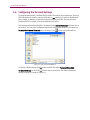
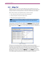
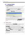
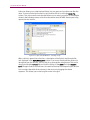
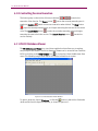
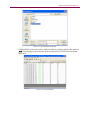
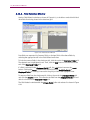
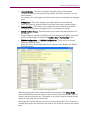
Chapter Four: Advanced Features | 81
Figure 4-30 System Configuration Window
10. The System Configuration window allows you to configure and verify individual
application settings.
For example, to verify C2K settings, click the Start button next to C2K application,
disable Remote Mode, and configure the C2K settings using the TASKIT C2K GUI.
NOTE: When you load a Device file in the utility, only the path is noted. The file
contents can still be changed.
11. When changing from C2K to EV-DO, you must set the base station to the appropriate
application.
12. Select the application using the Agilent 8960 settings in the System Configuration
window, as shown in Figure 4-30.
You must start either C2K or EV-DO before the 8960 displays the available
applications.
13. Click the Query Device to query the 8960.
Available C2K and EV-DO choices are populated and you can set the preferred
application.
This step is necessary after upgrading the 8960, or using a different system.
These settings are stored in the MSF.ini file and loaded automatically when the
application is started.
14. After completing System Configuration, proceed to executing the session.
NOTE: The system will stop and prompt for user-assisted tests and system failures.
82 | EV-DO ATS User Manual
4.16.Email Notification
4.16.1. Overview
This feature enables automated email notification. The Email Notification allows you to
have emails sent about events occurring in EV-DO. To set up Email Notifications, select
Config>Email Notification. The Email Notification window displays, as shown in Figure
4-31.
Figure 4-31: Email Notification Window
You can set the following parameters in the Email Notification window:
•
Enable Email Notification:
This parameter allows you to enable or disable email notification. By default, email
notification is disabled.
•
Email To:
This parameter allows you to specify an email address. Separate multiple email
addresses with semi-colons.
•
Maximum number of emails to send:
This parameter limits the number of emails sent for a given run of EV-DO. While
running a session, EV-DO resets this parameter at the session level. When running a
suite, EV-DO resets this parameter at the suite level.
•
EV-DO Starts:
Sends an email when EV-DO starts. With this option, Email Notification needs to be
enabled.
•
EV-DO Stops:
Sends an email when EV-DO stops. With this option, Email Notification needs to be
enabled.
Chapter Four: Advanced Features | 83
•
Fatal Errors:
Sends an email when there are fatal errors. These include; failure to connect to
instruments, mobile failed to register, and failure to connect to UDM. With this
option, Email Notification needs to be enabled.
•
Number of Undetermined Exceeds:
Sends an email when the number of undetermined test results exceeds the specified
limit. With this option, Email Notification needs to be enabled.
4.16.2. Requirements
You are required to configure the IIS SMTP Virtual Server on the machine running
TestDrive EV-DO.
To configure the IIS SMTP Virtual Server:
1. Select Start>Control Panel.
2. Under Administrative Tools, open Internet Information Services.
3. Under the left pane in the Internet Information Services window, right-click Default
SMTP Virtual Server and select Properties.
4. The Default SMTP Virtual Server Properties window displays.
Select the Delivery tab and click Outbound Security.
5. Under Outbound Security, select Integrated Windows Authentication, enter a valid
username and password and click OK.
6. Under the Delivery tab, click the Advanced button.
7. The Advanced Delivery Options window displays.
Enter the name of your email server for Smart Host and click OK.
To use the IP Address instead of the server name, enter it in square brackets “[ ]” to
tell Windows to look for an IP Address during the DNS Look-up.
Note that DNS Look-up is an expensive operation.
8. Under the Delivery tab, click the Apply button, and then click OK.
9. The SMTP Virtual Server Configuration is now complete.
5. Troubleshooting EV-DO ATS
5.1. Overview
The following section is a reference guide for troubleshooting problems with test
execution.
EV-DO ATS is designed to make testing Access Terminal devices as simple as possible.
However, as with any complex system, it is possible to encounter difficulty when using
EV-DO ATS. This section provides useful information to troubleshoot such difficulty.
EV-DO ATS has a diagnostic utility built into the TestDrive EV-DO software. This feature
can evaluate the current RF cabling to determine if the system has been cabled correctly.
It also determines if the instruments can be controlled via GPIB. There is additional
information in this chapter regarding errors that occur while validating and executing a
test suite.
Although a test suite may execute properly, the actual results may look incorrect. A
separate section of this chapter addresses such unexpected results. Finally, a list of
frequently asked questions (FAQs) and their associated answers appear at the end of
this chapter.
5.2. System Diagnostics
The TestDrive EV-DO System Diagnostic procedure is a useful tool for debugging system
level problems such as, incorrect software configuration, incorrect control or RF cable
configuration, and malfunctioning equipment.
This procedure is not meant for performing calibration of system hardware. If any of the
Spirent hardware needs to be calibrated, refer to the User Manual for the specific
instrument.
If the diagnostics procedure fails, a debug tool (refer to Section 5.2.3 on page 88 for
more details) is located in the Utilities subfolder where the TestDrive EV-DO application
is installed. The default location is: C:\Program Files\TestDrive\EV-DO\Utilities.
This folder can also be used to troubleshoot other diagnostic failures.
Chapter Five: Troubleshooting | 85
5.2.1.
Instrument Requirements
The following instruments must be installed in the system to execute this procedure:
•
Agilent 8960 (one to three)
•
Agilent ESA series Spectrum Analyzer
•
SR3452 V2 CDMA Network Emulator (two)
•
SR3462 EV-DO Network Emulator
•
Agilent 3499, TAS5408 and SR5068 Test Configuration Units
•
GPIB and RF cables includes in the TCU-KIT.
Additionally, the TestDrive EV-DO System tests the following optional equipment if
connected to your system:
•
Spirent SR5500 Wireless Channel Emulator
•
ESG4438B Signal Generators (two)
5.2.2.
Diagnostic Procedures
Prior to executing this procedure, ensure your system is configured as outlined in the
Rack Setup Guide.
To execute the diagnostic procedure, select Execute>System Diagnostics, and then
click the Run button.
The EV-DO Diagnostic Procedure window displays while the diagnostic procedure is
executing, as shown in Figure 5-1.
Figure 5-1: EV-DO Diagnostic Procedure Window
86 | EV-DO ATS User Manual
The following steps describe the functions performed when the System Diagnostic
procedure is executed. If you detect errors while the procedure is executing, the software
displays a list of possible causes in a message box. Additionally, these descriptions are
documented below for convenience.
Step 0 – Initializing HW
This procedure attempts to communicate with all required system hardware. If TestDrive
EV-DO software or any control cables are incorrectly configured, it is detected by this
test. If this test fails, the most likely causes are:
•
Required instrument HW is not enabled. Check the ‘Communications’ settings from
the ‘Software’ menu.
•
Incorrect GPIB addresses have been selected. Verify that ‘Communications’ setting in
the ‘Software’ menu match the instrument configurations. Each instrument should
have a unique GPIB address.
•
GPIB cables have not been properly connected to one or more instruments.
•
One or more instruments have not been powered on.
•
GPIB card has not been installed/configured correctly in the test PC.
Steps 1&2 – Checking 8960
This procedure verifies the RF generator in the Agilent 8960 and the measurement
capability of the Spectrum Analyzer. Additional it verifies that the Agilent 3499, TAS5048
and SR5068 are working, and that some of the RF cables have been correctly configured.
If this test fails, the most likely causes are:
•
Power has not been applied to the TAS5048 or SR5068. This can be verified by
checking the green status LED on the front panel.
•
The custom control cable is not securely connected from the Agilent 3499 to the
TAS5048.
•
Cable C3 is not securely connected from the Agilent 8960 RF IN/OUT port to the
TAS5048 P3 port.
•
Cable C1 is not securely connected from the Spectrum Analyzer RF IN port to the
TAS5048 P1 port.
Additionally it is possible that one of the following instruments is malfunctioning:
Agilent 8960, Agilent 3499, TAS5048, SR5068 or Agilent Spectrum Analyzer
Up to two auxiliary Agilent 8960 units are checked in this step if Rev. B protocol tests are
permit.
Step 3 – Checking the Channel Emulator Auto Range
This procedure verifies the SR5500 is receiving a signal at the appropriate level and can
perform an auto-range function. If this test fails, the following are the most likely causes:
•
Cable C5 is not securely connected from the SR5500 Channel #1 IN port to the
TAS5048 P5 port.
Additionally it is possible that one of the following instruments is malfunctioning:
Chapter Five: Troubleshooting | 87
TAS5048, SR5068 and Agilent 3499A
Step 4 – Checking Channel Emulator Output Level
This procedure verifies the SR5500 Channel #1 main signal path is operational. If this
test fails, the following are the most likely causes:
•
Cable C10 is not securely connected from the SR5500 Channel #1 OUT port to the
SR5068 P3 port.
•
There is no loopback cable connected from the SR5500 Channel #1 LO OUT to
Channel #1 LO IN.
Step 5 – Checking Channel Emulator Bypass Level
This procedure verifies the SR5500 Channel #1 Bypass feature is working properly. If this
test fails, the following are the most likely causes:
•
SR5500 may be operating out of spec.
Step 6 – Checking Channel Emulator Channel 1 with AMP
This procedure verifies the SR5500 and amplifier in the path is working properly. If this
test fails, the following are the most likely causes:
•
SR5500 may be operating out of spec.
•
Amplifier may be malfunctioning.
Step 7 – Checking Channel Emulator Channel 2 output level in Diversity Mode
This procedure verifies the SR5500 in diversity mode is working properly. If this test fails,
the following are the most likely causes:
•
SR5500 Diversity Mode may be operating out of spec.
Step 8– Checking Channel Emulator Channel 2 output level in Diversity Mode with
amplifier
This procedure verifies the SR5500 in the diversity path with amplifier is working
properly.
Steps 9-19 are no longer necessary.
Steps 20 & 21 – Checking ESG #1 Output Amplitude and Frequency
This procedure verifies that the ESG #1 is working properly. If this test fails, the following
are the most likely causes:
•
Cable C7 is not securely connected to the 1U Filler Panel P2 port.
•
Cable C22 is not securely connected to the SR5068 P11 port
Steps 22 & 23 – Checking ESG #2 Output Amplitude and Frequency
This procedure verifies that the ESG #2 is working properly. If this test fails, the following
are the most likely causes:
•
Cable C8 is not securely connected to the 1U Filler Panel P1 port.
88 | EV-DO ATS User Manual
•
Cable C21 is not securely connected to the SR5068 P13 port.
Steps 24 - 27– Checking ESG #1 Output Amplitude and Frequency I with amplifiers
in the path
This procedure verifies that the AirAccess channel 1 is working properly. If this test fails,
the following are the most likely causes:
•
Cable C7 is not securely connected to the SR5068 P7 port.
Step 28– Checking AA Channel 1 output level
This procedure verifies that the AirAccess channel 1 is working properly. If this test fails,
the following are the most likely causes:
•
Cable C16 is not securely connected to the SR5500 channel2 input.
Step 29– Checking Channel Emulator channel 2 auto-range
This procedure verifies that the channel emulator channel 2 is working properly. If this
test fails, the following are the most likely causes:
•
Channel Emulator channel 2 auto-range function may not work properly.
Step 30– Checking AA Channel 2 output level
This procedure verifies that the AirAccess channel 2 is working properly. If this test fails,
the following are the most likely causes:
•
Cable C16 is not securely connected to the SR5500 channel2 input.
Step 31– Checking Channel Emulator channel 2 Bypass mode
This procedure verifies that the channel emulator channel 2 is working properly in
bypass mode.
Step 32– Checking Channel Emulator channel 2 output level with an amplifier
This procedure verifies that the channel emulator channel 2 with an amplifier in the path
is working properly.
5.2.3.
Diagnostic Debugger
The Diagnostic Debugger supports both C2K-ATS and EV-DO TestDrive systems, up to the
latest release. If any step after Initialization fails, start the Diagnostics Debugger by
opening the C2K_Diag_Debug.exe file. During the process, leave the C2K and/or EV-DO
Executive windows open.
An “N-type” female-female connector and a torque wrench are needed to change cable
connections.
After opening the C2K_Diag_Debug.exe file, the Diagnostic Debugger window displays,
as shown in Figure 5-2.
The following sections of the Diagnostics Debugger window are the most relevant for
debugging a failed diagnostic process:
Chapter Five: Troubleshooting | 89
•
Instruction Pane –This pane is located in the upper section of the window.
The pane allows you to set Instrument Parameters, Re-cable Connections, and set
measurements.
The settings prior to debugging are shown in the Instruction Pane when the debugger
starts.
•
Debug Steps – This menu displays in the upper-right corner of the window.
Select the diagnostic step that failed from the pull-down menu to view the steps.
•
Connect Button – This button is in the upper-left section of the window. Before
debugging, the Diagnostics Debugger must be connected to the system.
•
Switch Position Panels –These two panels are located in the lower-left section of
the window.
There are eight (8) switches for SR5048 and six (6) switches for SR5068. Set the two
positions of each switch by clicking the Position One or Position Two button.
•
SR5048 Configuration and SR5068 Configuration – These menus are located
under the Instruction Panel.
Select the standard paths determined by the switches of the SR5048 and SR5068
from these menus.
Figure 5-2: Diagnostics Debugger Window
After connecting to the system, select the failed debug step from the Debug Steps
menu, and follow the instructions given in the Instruction Pane. Note that the steps are
shown in the chronological order. For example, in any chosen step, we assume that the
diagnostic steps have passed successfully.
Most diagnostics failures require more than one step to debug them. This is the reason
multiple debug paths and instructions are shown in the Instruction Pane for each Debug
Step.
90 | EV-DO ATS User Manual
The switch connections in the SR5048 and SR5068 paths are set by the debugger after
selecting a debug step. To reset the diagnostic path manually, select the path from the
TAS5048 Configuration and TAS5068 Configuration menus.
Click the NEXT button to proceed to the next step in the debugging procedure.
Make sure to reconnect the cables as shown in Setup Guide before beginning to debug
another diagnostics path.
5.3. Test Validation Errors
The Validate Suite function from the Execute Menu examines the test parameters in the
suite. This operation can significantly reduce the risk of problems during test execution
by detecting parameter conflicts beforehand. Some of the errors that could occur during
suite validation are listed below:
Insufficient hardware for test; [Instrument] not detected.
The indicated instrument is required to run the test, but was not found. Make sure the
indicated instrument is on the GPIB bus, set to present in the Communications window,
and set to the correct GPIB address.
Insufficient hardware for noise and tone simulation simultaneously.
If both noise and interfering tones are selected as impairments, this error will be
generated during suite validation. Both impairments cannot be selected simultaneously.
Insufficient hardware fader requires noise to be present; Fader not detected.
If fading is enabled for a test, the SR5500 must be present for the test to execute.
Parameter out of range.
Parameters are checked against a maximum range when entered in the Test Settings
grid. Some parameters have ranges that are affected by the ranges of other parameters.
Therefore, setting a value for a related parameter could cause the other parameter to be
out of range. This error is generated as a result.
Chapter Five: Troubleshooting | 91
5.4. Test Execution Errors
While a suite is executing, execution errors are listed in a grid in the TestDrive EV-DO
suite window. View the errors by clicking the test execution button in the results area
(lower right) of the suite window. Each line in the grid represents a single error. For each
error, the test number, error number, and description are listed.
This section elaborates on the condition for specific test execution errors and gives
helpful information to resolve the error. Note that TestDrive EV-DO is designed to handle
errors without failure. This means that if an error occurs, the test proceeds as far as
possible. If a test must be skipped due to errors, its status is given as “Undetermined”.
After the error is resolved, the test must be executed again to collect the results.
5.4.1.
Terminal Fails to Open a Session and or Setup Data
Connections
TestDrive EV-DO attempts to open a session between the Terminal and the Base Station
Emulator at the beginning of a suite. For each test that executes TestDrive EV-DO will
setup a data connection. If the Data Connection drops while a suite is executed,
TestDrive EV-DO will setup the connection again.
There are many possible reasons for failure of the Terminal to open a data session or
setup a data connection. The following details some of the causes and suggests ways to
resolve the problem.
Cause #1: The RF Cabling in EV-DO ATS is incorrect.
Use the setup information in this manual or the quick setup poster to verify the cabling.
Use the System Diagnostic feature described earlier in this chapter to ensure proper
cabling.
Cause #2: There is a problem with the Terminal.
Verify the following information with regards to the Terminal:
•
The Terminal is EV-DO Terminal device.
•
The Terminal features an RF interface that is working correctly.
•
The Terminal is powered on and has enough power to operate correctly. Is the
Terminal powered by an external power supply instead of its own AC adapter or
battery? Is that external power supply set correctly for the Terminal’s power
interface? The Terminal may be powered on and its User Interface may operate, but
the RF interface may not operate correctly if it is not powered properly.
•
The Terminal is properly interfaced to EV-DO ATS. The RF connection to the Terminal
device is reliable and appropriately accounted for in the Terminal correction factor in
TestDrive EV-DO. Note that some RF interfaces can “wear out” with too much physical
handling. Sometimes these interfaces become intermittent. To help determine such
a case, adjust the physical RF connection and see if the Terminal responds.
92 | EV-DO ATS User Manual
•
The Terminal device should be setup to allow roaming, so that non-home SID’s and
non-home channels will be allowed (searched).
Cause #3: The Terminal setup information is incorrect in TestDrive EV-DO.
Due the parameters test in the Terminal File match those required by the device under
tests? Pay particular attention to the Channel Number and Band Class.
Cause #4: The Terminal does not have enough time or attempts to setup a Data
Connection.
Adjust the Data Connection Setup parameters in the Terminal window to allow more
retries or more time per retry (Connect timeout, Retry Delay, Number of Retries).
Cause #5: The hardware setup information is incorrect in TestDrive EV-DO.
Make sure the settings are correct in the Communications window in TestDrive EV-DO
(select Communications from the Options menu). If an instrument is set to Not Present,
be sure it is not in the RF cabling configuration. This can cause unpredictable results.
Cause #6: The Terminal correction information is incorrect in TestDrive EV-DO.
Use the lower half of the Terminal window to configure the Terminal correction
information. TestDrive EV-DO uses this information to ensure an accurate power level
reaches the Terminal.
Cause #7: The system calibration information is incorrect in TestDrive EV-DO.
Perform the System Calibration procedure to ensure the correct calibration information is
in TestDrive EV-DO.
Cause #8: The incorrect Terminal file is being used in the suite.
Ensure that the correct Terminal file is being used in the suite. If you have the Terminal
file open, be sure any changes are saved before the suite is executed. Use the Window
menu to determine what files are open.
Cause #9: Terminal has not been configured for Subtype 2 Physical Layer. (If
executing TIA/EIA-866A/C.S0033-A test cases for Subtype 2 Physical Layer)
The following pertains to handsets using Qualcomm chipsets:
In order to execute C.S0033 Rev A test case, certain NV parameters need to be
configured. Using the Qualcomm NV browser, edit item 3458 to set the following:
•
Custom Config – TRUE
•
Subtype 2 Physical Layer – 1
•
Enhanced FTCMAC – 1
•
Subtype 3 RTCMAC – 1
Edit item 4202 and set the parameter to 0.
To ensure proper performance, verify these settings with the handset manufacturer.
Other recommendations include:
Chapter Five: Troubleshooting | 93
•
Connect the Base Station directly to the Access terminal to eliminate suspicious
hardware and verify the Terminal’s configuration. Remember to configure the
hardware and the software appropriately.
•
Use a Terminal device that is working correctly to ensure proper EV-DO ATS
operation. Remember to adjust the Terminal settings for each Terminal in use.
•
The Terminal is properly isolated from outside RF (other nearby cell sites and signal
sources).
5.4.2.
Impairments Too Severe for Data Connection
This particular error represents a unique condition. In order to setup Data Connections,
TestDrive EV-DO configures the RF conditions for no impairments and for a minimum
signal power level. Once the connection is established, the RF conditions are modified to
perform the test. After the RF conditions are modified, TestDrive EV-DO checks if the
connection is still setup. If the connection is not setup, this error is generated. This
implies that the Terminal is unable to correctly demodulate enough packets accurately to
maintain the connection. TestDrive EV-DO will list the test status as Undetermined and
proceed to the next test. Unfortunately, unless the connection can remain setup, the test
cannot be performed.
5.5. Unexpected Results
This section discusses some of the reasons why variations in results may exist and can
give helpful information for resolving these issues.
It is important the EV-DO ATS is setup correctly. It is a good idea to review the causes for
session open and Data Connection failures earlier in this chapter. Some of the reasons
for unexpected results are the same as some of the reasons for registration and call
setup failure. Pay particular attention to:
•
RF Cabling
•
System Calibration
•
Terminal Correction Factor in the Terminal window
Terminal devices are expected to perform differently under different RF conditions. For
example, if the same test is performed at a different frequency, it is common to see a
difference in the results. Another example is the power level at which the test is
performed. It is possible to see a difference in the Spurious Response of the Terminal
device when it is transmitting at a different power level.
94 | EV-DO ATS User Manual
5.6. Frequently Asked Questions
How do I change the test type in the Suite window?
It is not possible to change the test type for an existing test. You must first delete the
existing test. Once the test is deleted and the space in the grid is blank, you may select a
new test type.
How do I edit the parameters for a test?
While looking at the suite window you can click on the test title column on any of the
rows. This will update the grid in the upper right part of the window with all settable
parameters related to the test of the row on which you clicked. In general if you click or
select a test, the frame to the right will be showing the settable parameters of the row
(test) pertaining to the column title.
Why Do I get an error when I attempt to ‘Verify Hardware’?
The Verify Hardware feature in the Communications window attempts to communicate
with the remote instruments, obtain some information about them and update the
information displayed in the Communications window. TestDrive EV-DO will only
communicate to the instruments using GPIB. Be sure you computer is equipped with a
National Instruments GPIB card and that the instruments are correctly connected to the
PC using GPIB cables. Also, make sure the GPIB addresses of the instruments match the
setting in the Communications window. Each instrument must have a unique GPIB
address. You must do this manually at the front panel of each instrument. Be sure each
instrument is powered on and ready for remote control.
Why can’t I edit a value printed in blue?
Values printed in blue indicate read only parameters. You cannot change these
parameters directly. Refer to specific parameters to understand how to change them or
why they are read-only.
I see “Over Range” or “Under Range” errors on the 8960 front Panel, is this a
problem?
This is not a problem. During the course of a suite execution TestDrive EV-DO will setup
test conditions using a variety of system configurations. These changes include
switching instruments in and out of the forward and reverse path. These changes will
cause wide variations of path loss. Since it is not possible to simultaneously change
system configurations and Base Station Emulator offsets there will be short instances
where the forward and reverse path losses are not accurately specified in the base
station emulator. This is when this error is displayed. The error is not automatically
cleared from the screen even when the problem is resolved. Spirent engineers have
spent considerable time verifying that at test execution time all levels and offset values
are correct ensuring that an “over range” or “under range” condition does not really
exist.