1
MELSEC iQ-R Ethernet
User's Manual (Application)
-RJ71EN71
-R04CPU
-R04ENCPU
-R08CPU
-R08ENCPU
-R08PCPU
-R08SFCPU
-R16CPU
-R16ENCPU
-R16PCPU
-R16SFCPU
-R32CPU
-R32ENCPU
-R32PCPU
-R32SFCPU
-R120CPU
-R120ENCPU
-R120PCPU
-R120SFCPU
SAFETY PRECAUTIONS
(Read these precautions before using this product.)
Before using this product, please read this manual and the relevant manuals carefully and pay full attention to safety to handle
the product correctly.
The precautions given in this manual are concerned with this product only. For the safety precautions of the programmable
controller system, refer to the MELSEC iQ-R Module Configuration Manual.
In this manual, the safety precautions are classified into two levels: "
WARNING" and "
CAUTION".
WARNING
Indicates that incorrect handling may cause hazardous conditions, resulting in
death or severe injury.
CAUTION
Indicates that incorrect handling may cause hazardous conditions, resulting in
minor or moderate injury or property damage.
Under some circumstances, failure to observe the precautions given under "
CAUTION" may lead to serious
consequences.
Observe the precautions of both levels because they are important for personal and system safety.
Make sure that the end users read this manual and then keep the manual in a safe place for future reference.
[Design Precautions]
WARNING
● Configure safety circuits external to the programmable controller to ensure that the entire system
operates safely even when a fault occurs in the external power supply or the programmable controller.
Failure to do so may result in an accident due to an incorrect output or malfunction.
(1) Emergency stop circuits, protection circuits, and protective interlock circuits for conflicting
operations (such as forward/reverse rotations or upper/lower limit positioning) must be configured
external to the programmable controller.
(2) When the programmable controller detects an abnormal condition, it stops the operation and all
outputs are:
• Turned off if the overcurrent or overvoltage protection of the power supply module is activated.
• Held or turned off according to the parameter setting if the self-diagnostic function of the CPU
module detects an error such as a watchdog timer error.
(3) All outputs may be turned on if an error occurs in a part, such as an I/O control part, where the
CPU module cannot detect any error. To ensure safety operation in such a case, provide a safety
mechanism or a fail-safe circuit external to the programmable controller. For a fail-safe circuit
example, refer to "General Safety Requirements" in the MELSEC iQ-R Module Configuration
Manual.
(4) Outputs may remain on or off due to a failure of a component such as a relay and transistor in an
output circuit. Configure an external circuit for monitoring output signals that could cause a
serious accident.
● In an output circuit, when a load current exceeding the rated current or an overcurrent caused by a
load short-circuit flows for a long time, it may cause smoke and fire. To prevent this, configure an
external safety circuit, such as a fuse.
● Configure a circuit so that the programmable controller is turned on first and then the external power
supply. If the external power supply is turned on first, an accident may occur due to an incorrect output
or malfunction.
● For the operating status of each station after a communication failure, refer to manuals relevant to the
network. Incorrect output or malfunction due to a communication failure may result in an accident.
1
[Design Precautions]
WARNING
● When connecting an external device with a CPU module or intelligent function module to modify data
of a running programmable controller, configure an interlock circuit in the program to ensure that the
entire system will always operate safely. For other forms of control (such as program modification,
parameter change, forced output, or operating status change) of a running programmable controller,
read the relevant manuals carefully and ensure that the operation is safe before proceeding. Improper
operation may damage machines or cause accidents.
● Especially, when a remote programmable controller is controlled by an external device, immediate
action cannot be taken if a problem occurs in the programmable controller due to a communication
failure. To prevent this, configure an interlock circuit in the program, and determine corrective actions
to be taken between the external device and CPU module in case of a communication failure.
● Do not write any data to the "system area" and "write-protect area" of the buffer memory in the
module. Also, do not use any "use prohibited" signals as an output signal from the CPU module to
each module. Doing so may cause malfunction of the programmable controller system. For the
"system area", "write-protect area", and the "use prohibited" signals, refer to the user's manual for the
module used.
● If a communication cable is disconnected, the network may be unstable, resulting in a communication
failure of multiple stations. Configure an interlock circuit in the program to ensure that the entire
system will always operate safely even if communications fail. Failure to do so may result in an
accident due to an incorrect output or malfunction.
● To maintain the safety of the programmable controller system against unauthorized access from
external devices via the network, take appropriate measures. To maintain the safety against
unauthorized access via the Internet, take measures such as installing a firewall.
2
[Design Precautions]
CAUTION
● Do not install the control lines or communication cables together with the main circuit lines or power
cables. Keep a distance of 100mm or more between them. Failure to do so may result in malfunction
due to noise.
● During control of an inductive load such as a lamp, heater, or solenoid valve, a large current
(approximately ten times greater than normal) may flow when the output is turned from off to on.
Therefore, use a module that has a sufficient current rating.
● After the CPU module is powered on or is reset, the time taken to enter the RUN status varies
depending on the system configuration, parameter settings, and/or program size. Design circuits so
that the entire system will always operate safely, regardless of the time.
● Do not power off the programmable controller or reset the CPU module while the settings are being
written. Doing so will make the data in the flash ROM undefined. The values need to be set in the
buffer memory and written to the flash ROM again. Doing so also may cause malfunction or failure of
the module.
● When changing the operating status of the CPU module from external devices (such as the remote
RUN/STOP functions), select "Do Not OPEN in Program" for "Open Method Setting" in the module
parameters. If "OPEN in Program" is selected, an execution of the remote STOP function causes the
communication line to close. Consequently, the CPU module cannot reopen the line, and external
devices cannot execute the remote RUN function.
3
[Installation Precautions]
WARNING
● Shut off the external power supply (all phases) used in the system before mounting or removing the
module. Failure to do so may result in electric shock or cause the module to fail or malfunction.
[Installation Precautions]
CAUTION
● Use the programmable controller in an environment that meets the general specifications in the Safety
Guidelines included with the base unit. Failure to do so may result in electric shock, fire, malfunction,
or damage to or deterioration of the product.
● To mount a module, place the concave part(s) located at the bottom onto the guide(s) of the base unit,
and push in the module until the hook(s) located at the top snaps into place. Incorrect interconnection
may cause malfunction, failure, or drop of the module.
● When using the programmable controller in an environment of frequent vibrations, fix the module with
a screw.
● Tighten the screws within the specified torque range. Undertightening can cause drop of the screw,
short circuit, or malfunction. Overtightening can damage the screw and/or module, resulting in drop,
short circuit, or malfunction.
● When using an extension cable, connect it to the extension cable connector of the base unit securely.
Check the connection for looseness. Poor contact may cause malfunction.
● When using an SD memory card, fully insert it into the SD memory card slot. Check that it is inserted
completely. Poor contact may cause malfunction.
● Securely insert an extended SRAM cassette into the cassette connector of the CPU module. After
insertion, close the cassette cover and check that the cassette is inserted completely. Poor contact
may cause malfunction.
● Do not directly touch any conductive parts and electronic components of the module, SD memory
card, extended SRAM cassette, or connector. Doing so can cause malfunction or failure of the
module.
[Wiring Precautions]
WARNING
● Shut off the external power supply (all phases) used in the system before installation and wiring.
Failure to do so may result in electric shock or cause the module to fail or malfunction.
● After installation and wiring, attach the included terminal cover to the module before turning it on for
operation. Failure to do so may result in electric shock.
4
[Wiring Precautions]
CAUTION
● Individually ground the FG and LG terminals of the programmable controller with a ground resistance
of 100 ohms or less. Failure to do so may result in electric shock or malfunction.
● Use applicable solderless terminals and tighten them within the specified torque range. If any spade
solderless terminal is used, it may be disconnected when the terminal screw comes loose, resulting in
failure.
● Check the rated voltage and signal layout before wiring to the module, and connect the cables
correctly. Connecting a power supply with a different voltage rating or incorrect wiring may cause fire
or failure.
● Connectors for external devices must be crimped or pressed with the tool specified by the
manufacturer, or must be correctly soldered. Incomplete connections may cause short circuit, fire, or
malfunction.
● Securely connect the connector to the module. Poor contact may cause malfunction.
● Do not install the control lines or communication cables together with the main circuit lines or power
cables. Keep a distance of 100mm or more between them. Failure to do so may result in malfunction
due to noise.
● Place the cables in a duct or clamp them. If not, dangling cable may swing or inadvertently be pulled,
resulting in damage to the module or cables or malfunction due to poor contact. Do not clamp the
extension cables with the jacket stripped.
● Check the interface type and correctly connect the cable. Incorrect wiring (connecting the cable to an
incorrect interface) may cause failure of the module and external device.
● Tighten the terminal screws or connector screws within the specified torque range. Undertightening
can cause drop of the screw, short circuit, fire, or malfunction. Overtightening can damage the screw
and/or module, resulting in drop, short circuit, fire, or malfunction.
● When disconnecting the cable from the module, do not pull the cable by the cable part. For the cable
with connector, hold the connector part of the cable. For the cable connected to the terminal block,
loosen the terminal screw. Pulling the cable connected to the module may result in malfunction or
damage to the module or cable.
● Prevent foreign matter such as dust or wire chips from entering the module. Such foreign matter can
cause a fire, failure, or malfunction.
● A protective film is attached to the top of the module to prevent foreign matter, such as wire chips,
from entering the module during wiring. Do not remove the film during wiring. Remove it for heat
dissipation before system operation.
● Programmable controllers must be installed in control panels. Connect the main power supply to the
power supply module in the control panel through a relay terminal block. Wiring and replacement of a
power supply module must be performed by qualified maintenance personnel with knowledge of
protection against electric shock. For wiring, refer to the MELSEC iQ-R Module Configuration Manual.
● For Ethernet cables to be used in the system, select the ones that meet the specifications in the user's
manual for the module used. If not, normal data transmission is not guaranteed.
5
[Startup and Maintenance Precautions]
WARNING
● Do not touch any terminal while power is on. Doing so will cause electric shock or malfunction.
● Correctly connect the battery connector. Do not charge, disassemble, heat, short-circuit, solder, or
throw the battery into the fire. Also, do not expose it to liquid or strong shock. Doing so will cause the
battery to produce heat, explode, ignite, or leak, resulting in injury and fire.
● Shut off the external power supply (all phases) used in the system before cleaning the module or
retightening the terminal screws, connector screws, or module fixing screws. Failure to do so may
result in electric shock.
[Startup and Maintenance Precautions]
CAUTION
● When connecting an external device with a CPU module or intelligent function module to modify data
of a running programmable controller, configure an interlock circuit in the program to ensure that the
entire system will always operate safely. For other forms of control (such as program modification,
parameter change, forced output, or operating status change) of a running programmable controller,
read the relevant manuals carefully and ensure that the operation is safe before proceeding. Improper
operation may damage machines or cause accidents.
● Especially, when a remote programmable controller is controlled by an external device, immediate
action cannot be taken if a problem occurs in the programmable controller due to a communication
failure. To prevent this, configure an interlock circuit in the program, and determine corrective actions
to be taken between the external device and CPU module in case of a communication failure.
● Do not disassemble or modify the modules. Doing so may cause failure, malfunction, injury, or a fire.
● Use any radio communication device such as a cellular phone or PHS (Personal Handy-phone
System) more than 25cm away in all directions from the programmable controller. Failure to do so
may cause malfunction.
● Shut off the external power supply (all phases) used in the system before mounting or removing the
module. Failure to do so may cause the module to fail or malfunction.
● Tighten the screws within the specified torque range. Undertightening can cause drop of the
component or wire, short circuit, or malfunction. Overtightening can damage the screw and/or module,
resulting in drop, short circuit, or malfunction.
● After the first use of the product, do not mount/remove the module to/from the base unit, and the
terminal block to/from the module, and do not insert/remove the extended SRAM cassette to/from the
CPU module more than 50 times (IEC 61131-2 compliant) respectively. Exceeding the limit may cause
malfunction.
● After the first use of the product, do not insert/remove the SD memory card to/from the CPU module
more than 500 times. Exceeding the limit may cause malfunction.
● Do not touch the metal terminals on the back side of the SD memory card. Doing so may cause
malfunction or failure of the module.
● Do not touch the integrated circuits on the circuit board of an extended SRAM cassette. Doing so may
cause malfunction or failure of the module.
6
[Startup and Maintenance Precautions]
CAUTION
● Do not drop or apply shock to the battery to be installed in the module. Doing so may damage the
battery, causing the battery fluid to leak inside the battery. If the battery is dropped or any shock is
applied to it, dispose of it without using.
● Startup and maintenance of a control panel must be performed by qualified maintenance personnel
with knowledge of protection against electric shock. Lock the control panel so that only qualified
maintenance personnel can operate it.
● Before handling the module, touch a conducting object such as a grounded metal to discharge the
static electricity from the human body. Failure to do so may cause the module to fail or malfunction.
[Operating Precautions]
CAUTION
● When changing data and operating status, and modifying program of the running programmable
controller from an external device such as a personal computer connected to an intelligent function
module, read relevant manuals carefully and ensure the safety before operation. Incorrect change or
modification may cause system malfunction, damage to the machines, or accidents.
● Do not power off the programmable controller or reset the CPU module while the setting values in the
buffer memory are being written to the flash ROM in the module. Doing so will make the data in the
flash ROM undefined. The values need to be set in the buffer memory and written to the flash ROM
again. Doing so can cause malfunction or failure of the module.
[Disposal Precautions]
CAUTION
● When disposing of this product, treat it as industrial waste.
● When disposing of batteries, separate them from other wastes according to the local regulations. For
details on battery regulations in EU member states, refer to the MELSEC iQ-R Module Configuration
Manual.
[Transportation Precautions]
CAUTION
● When transporting lithium batteries, follow the transportation regulations. For details on the regulated
models, refer to the MELSEC iQ-R Module Configuration Manual.
● The halogens (such as fluorine, chlorine, bromine, and iodine), which are contained in a fumigant
used for disinfection and pest control of wood packaging materials, may cause failure of the product.
Prevent the entry of fumigant residues into the product or consider other methods (such as heat
treatment) instead of fumigation. The disinfection and pest control measures must be applied to
unprocessed raw wood.
7
CONDITIONS OF USE FOR THE PRODUCT
(1) Mitsubishi programmable controller ("the PRODUCT") shall be used in conditions;
i) where any problem, fault or failure occurring in the PRODUCT, if any, shall not lead to any major or serious accident;
and
ii) where the backup and fail-safe function are systematically or automatically provided outside of the PRODUCT for the
case of any problem, fault or failure occurring in the PRODUCT.
(2) The PRODUCT has been designed and manufactured for the purpose of being used in general industries.
MITSUBISHI SHALL HAVE NO RESPONSIBILITY OR LIABILITY (INCLUDING, BUT NOT LIMITED TO ANY AND ALL
RESPONSIBILITY OR LIABILITY BASED ON CONTRACT, WARRANTY, TORT, PRODUCT LIABILITY) FOR ANY
INJURY OR DEATH TO PERSONS OR LOSS OR DAMAGE TO PROPERTY CAUSED BY the PRODUCT THAT ARE
OPERATED OR USED IN APPLICATION NOT INTENDED OR EXCLUDED BY INSTRUCTIONS, PRECAUTIONS, OR
WARNING CONTAINED IN MITSUBISHI'S USER, INSTRUCTION AND/OR SAFETY MANUALS, TECHNICAL
BULLETINS AND GUIDELINES FOR the PRODUCT.
("Prohibited Application")
Prohibited Applications include, but not limited to, the use of the PRODUCT in;
• Nuclear Power Plants and any other power plants operated by Power companies, and/or any other cases in which the
public could be affected if any problem or fault occurs in the PRODUCT.
• Railway companies or Public service purposes, and/or any other cases in which establishment of a special quality
assurance system is required by the Purchaser or End User.
• Aircraft or Aerospace, Medical applications, Train equipment, transport equipment such as Elevator and Escalator,
Incineration and Fuel devices, Vehicles, Manned transportation, Equipment for Recreation and Amusement, and
Safety devices, handling of Nuclear or Hazardous Materials or Chemicals, Mining and Drilling, and/or other
applications where there is a significant risk of injury to the public or property.
Notwithstanding the above, restrictions Mitsubishi may in its sole discretion, authorize use of the PRODUCT in one or
more of the Prohibited Applications, provided that the usage of the PRODUCT is limited only for the specific
applications agreed to by Mitsubishi and provided further that no special quality assurance or fail-safe, redundant or
other safety features which exceed the general specifications of the PRODUCTs are required. For details, please
contact the Mitsubishi representative in your region.
INTRODUCTION
Thank you for purchasing the Mitsubishi MELSEC iQ-R series programmable controllers.
This manual describes the functions, programming, and troubleshooting of the relevant products listed below.
Before using this product, please read this manual and the relevant manuals carefully and develop familiarity with the
functions and performance of the MELSEC iQ-R series programmable controller to handle the product correctly.
When applying the program examples provided in this manual to an actual system, ensure the applicability and confirm that it
will not cause system control problems.
Please make sure that the end users read this manual.
Relevant products
RJ71EN71, CPU module
Unless otherwise specified, the buffer memory addresses in this manual are for when the P1 connecter of the
RJ71EN71 or RnENCPU is used.
Check the corresponding buffer memory addresses in the list and use the correct addresses when using the
following: (Page 191 Buffer Memory)
• CPU module (built-in Ethernet port part)
• P2 connector of the RJ71EN71
• RJ71EN71 (network type: Q-compatible Ethernet)
8
MEMO
9
CONTENTS
SAFETY PRECAUTIONS . . . . . . . . . . . . . . . . . . . . . . . . . . . . . . . . . . . . . . . . . . . . . . . . . . . . . . . . . . . . . . . . . . . .1
CONDITIONS OF USE FOR THE PRODUCT . . . . . . . . . . . . . . . . . . . . . . . . . . . . . . . . . . . . . . . . . . . . . . . . . . . .8
INTRODUCTION . . . . . . . . . . . . . . . . . . . . . . . . . . . . . . . . . . . . . . . . . . . . . . . . . . . . . . . . . . . . . . . . . . . . . . . . . . .8
RELEVANT MANUALS . . . . . . . . . . . . . . . . . . . . . . . . . . . . . . . . . . . . . . . . . . . . . . . . . . . . . . . . . . . . . . . . . . . . .13
TERMS . . . . . . . . . . . . . . . . . . . . . . . . . . . . . . . . . . . . . . . . . . . . . . . . . . . . . . . . . . . . . . . . . . . . . . . . . . . . . . . . .14
CHAPTER 1
1.1
FUNCTIONS
16
Connection with MELSOFT Product and GOT . . . . . . . . . . . . . . . . . . . . . . . . . . . . . . . . . . . . . . . . . . . . . . . . 16
Connection via a hub. . . . . . . . . . . . . . . . . . . . . . . . . . . . . . . . . . . . . . . . . . . . . . . . . . . . . . . . . . . . . . . . . . . . . . 16
Direct connection. . . . . . . . . . . . . . . . . . . . . . . . . . . . . . . . . . . . . . . . . . . . . . . . . . . . . . . . . . . . . . . . . . . . . . . . . 21
1.2
SLMP Communications . . . . . . . . . . . . . . . . . . . . . . . . . . . . . . . . . . . . . . . . . . . . . . . . . . . . . . . . . . . . . . . . . . 23
Applications . . . . . . . . . . . . . . . . . . . . . . . . . . . . . . . . . . . . . . . . . . . . . . . . . . . . . . . . . . . . . . . . . . . . . . . . . . . . . 23
Communication structure. . . . . . . . . . . . . . . . . . . . . . . . . . . . . . . . . . . . . . . . . . . . . . . . . . . . . . . . . . . . . . . . . . . 24
Data communication procedures. . . . . . . . . . . . . . . . . . . . . . . . . . . . . . . . . . . . . . . . . . . . . . . . . . . . . . . . . . . . . 24
List of valid commands . . . . . . . . . . . . . . . . . . . . . . . . . . . . . . . . . . . . . . . . . . . . . . . . . . . . . . . . . . . . . . . . . . . . 26
1.3
Communications Using the Predefined Protocol. . . . . . . . . . . . . . . . . . . . . . . . . . . . . . . . . . . . . . . . . . . . . . 28
Applicable connections . . . . . . . . . . . . . . . . . . . . . . . . . . . . . . . . . . . . . . . . . . . . . . . . . . . . . . . . . . . . . . . . . . . . 28
Data communication procedures. . . . . . . . . . . . . . . . . . . . . . . . . . . . . . . . . . . . . . . . . . . . . . . . . . . . . . . . . . . . . 29
Protocol communication type . . . . . . . . . . . . . . . . . . . . . . . . . . . . . . . . . . . . . . . . . . . . . . . . . . . . . . . . . . . . . . . 35
Packet elements . . . . . . . . . . . . . . . . . . . . . . . . . . . . . . . . . . . . . . . . . . . . . . . . . . . . . . . . . . . . . . . . . . . . . . . . . 36
Execution conditions of predefined protocol communications. . . . . . . . . . . . . . . . . . . . . . . . . . . . . . . . . . . . . . . 41
Example of predefined protocol communications . . . . . . . . . . . . . . . . . . . . . . . . . . . . . . . . . . . . . . . . . . . . . . . . 43
1.4
Socket Communications. . . . . . . . . . . . . . . . . . . . . . . . . . . . . . . . . . . . . . . . . . . . . . . . . . . . . . . . . . . . . . . . . . 52
Setting procedure . . . . . . . . . . . . . . . . . . . . . . . . . . . . . . . . . . . . . . . . . . . . . . . . . . . . . . . . . . . . . . . . . . . . . . . . 52
Applicable dedicated instructions . . . . . . . . . . . . . . . . . . . . . . . . . . . . . . . . . . . . . . . . . . . . . . . . . . . . . . . . . . . . 53
Applicable connections . . . . . . . . . . . . . . . . . . . . . . . . . . . . . . . . . . . . . . . . . . . . . . . . . . . . . . . . . . . . . . . . . . . . 53
Communication structure. . . . . . . . . . . . . . . . . . . . . . . . . . . . . . . . . . . . . . . . . . . . . . . . . . . . . . . . . . . . . . . . . . . 54
Communications using TCP/IP . . . . . . . . . . . . . . . . . . . . . . . . . . . . . . . . . . . . . . . . . . . . . . . . . . . . . . . . . . . . . . 55
Communications using UDP/IP . . . . . . . . . . . . . . . . . . . . . . . . . . . . . . . . . . . . . . . . . . . . . . . . . . . . . . . . . . . . . . 58
Broadcast communications . . . . . . . . . . . . . . . . . . . . . . . . . . . . . . . . . . . . . . . . . . . . . . . . . . . . . . . . . . . . . . . . . 59
Precautions . . . . . . . . . . . . . . . . . . . . . . . . . . . . . . . . . . . . . . . . . . . . . . . . . . . . . . . . . . . . . . . . . . . . . . . . . . . . . 59
1.5
Communications Using the Fixed Buffer . . . . . . . . . . . . . . . . . . . . . . . . . . . . . . . . . . . . . . . . . . . . . . . . . . . . 60
Differences between the "Procedure Exist" and "No Procedure" control methods . . . . . . . . . . . . . . . . . . . . . . . 60
Setting procedure . . . . . . . . . . . . . . . . . . . . . . . . . . . . . . . . . . . . . . . . . . . . . . . . . . . . . . . . . . . . . . . . . . . . . . . . 60
Applicable dedicated instructions . . . . . . . . . . . . . . . . . . . . . . . . . . . . . . . . . . . . . . . . . . . . . . . . . . . . . . . . . . . . 61
Applicable connections . . . . . . . . . . . . . . . . . . . . . . . . . . . . . . . . . . . . . . . . . . . . . . . . . . . . . . . . . . . . . . . . . . . . 61
Communication structure. . . . . . . . . . . . . . . . . . . . . . . . . . . . . . . . . . . . . . . . . . . . . . . . . . . . . . . . . . . . . . . . . . . 61
Send procedure . . . . . . . . . . . . . . . . . . . . . . . . . . . . . . . . . . . . . . . . . . . . . . . . . . . . . . . . . . . . . . . . . . . . . . . . . . 63
Receive procedure . . . . . . . . . . . . . . . . . . . . . . . . . . . . . . . . . . . . . . . . . . . . . . . . . . . . . . . . . . . . . . . . . . . . . . . 65
Pairing open . . . . . . . . . . . . . . . . . . . . . . . . . . . . . . . . . . . . . . . . . . . . . . . . . . . . . . . . . . . . . . . . . . . . . . . . . . . . 69
Broadcast communications . . . . . . . . . . . . . . . . . . . . . . . . . . . . . . . . . . . . . . . . . . . . . . . . . . . . . . . . . . . . . . . . . 70
Data Format. . . . . . . . . . . . . . . . . . . . . . . . . . . . . . . . . . . . . . . . . . . . . . . . . . . . . . . . . . . . . . . . . . . . . . . . . . . . . 70
Example of communications using the fixed buffer . . . . . . . . . . . . . . . . . . . . . . . . . . . . . . . . . . . . . . . . . . . . . . . 75
1.6
Communications Using the Random Access Buffer . . . . . . . . . . . . . . . . . . . . . . . . . . . . . . . . . . . . . . . . . . . 85
Setting procedure . . . . . . . . . . . . . . . . . . . . . . . . . . . . . . . . . . . . . . . . . . . . . . . . . . . . . . . . . . . . . . . . . . . . . . . . 85
Communication structure. . . . . . . . . . . . . . . . . . . . . . . . . . . . . . . . . . . . . . . . . . . . . . . . . . . . . . . . . . . . . . . . . . . 86
Procedure for reading from external device . . . . . . . . . . . . . . . . . . . . . . . . . . . . . . . . . . . . . . . . . . . . . . . . . . . . 86
Procedure for writing from external device . . . . . . . . . . . . . . . . . . . . . . . . . . . . . . . . . . . . . . . . . . . . . . . . . . . . . 87
10
Physical address and logical address of random access buffer . . . . . . . . . . . . . . . . . . . . . . . . . . . . . . . . . . . . . 88
Precautions . . . . . . . . . . . . . . . . . . . . . . . . . . . . . . . . . . . . . . . . . . . . . . . . . . . . . . . . . . . . . . . . . . . . . . . . . . . . . 88
Data Format. . . . . . . . . . . . . . . . . . . . . . . . . . . . . . . . . . . . . . . . . . . . . . . . . . . . . . . . . . . . . . . . . . . . . . . . . . . . . 88
Example of communications with random access buffer. . . . . . . . . . . . . . . . . . . . . . . . . . . . . . . . . . . . . . . . . . . 97
1.7
Link Dedicated Instruction Communication . . . . . . . . . . . . . . . . . . . . . . . . . . . . . . . . . . . . . . . . . . . . . . . . . . 97
Applicable dedicated instructions . . . . . . . . . . . . . . . . . . . . . . . . . . . . . . . . . . . . . . . . . . . . . . . . . . . . . . . . . . . . 97
Data communication procedures. . . . . . . . . . . . . . . . . . . . . . . . . . . . . . . . . . . . . . . . . . . . . . . . . . . . . . . . . . . . . 98
1.8
File Transfer Function (FTP server) . . . . . . . . . . . . . . . . . . . . . . . . . . . . . . . . . . . . . . . . . . . . . . . . . . . . . . . . . 98
Files that can be transferred with FTP. . . . . . . . . . . . . . . . . . . . . . . . . . . . . . . . . . . . . . . . . . . . . . . . . . . . . . . . 101
FTP command . . . . . . . . . . . . . . . . . . . . . . . . . . . . . . . . . . . . . . . . . . . . . . . . . . . . . . . . . . . . . . . . . . . . . . . . . . 101
Precautions . . . . . . . . . . . . . . . . . . . . . . . . . . . . . . . . . . . . . . . . . . . . . . . . . . . . . . . . . . . . . . . . . . . . . . . . . . . . 109
1.9
Time Setting Function (SNTP Client). . . . . . . . . . . . . . . . . . . . . . . . . . . . . . . . . . . . . . . . . . . . . . . . . . . . . . . 110
1.10
Security Function . . . . . . . . . . . . . . . . . . . . . . . . . . . . . . . . . . . . . . . . . . . . . . . . . . . . . . . . . . . . . . . . . . . . . . 112
IP filter function . . . . . . . . . . . . . . . . . . . . . . . . . . . . . . . . . . . . . . . . . . . . . . . . . . . . . . . . . . . . . . . . . . . . . . . . . 112
Remote password . . . . . . . . . . . . . . . . . . . . . . . . . . . . . . . . . . . . . . . . . . . . . . . . . . . . . . . . . . . . . . . . . . . . . . . 113
1.11
CONTENTS
Data communication procedures. . . . . . . . . . . . . . . . . . . . . . . . . . . . . . . . . . . . . . . . . . . . . . . . . . . . . . . . . . . . . 99
IP Address Change Function . . . . . . . . . . . . . . . . . . . . . . . . . . . . . . . . . . . . . . . . . . . . . . . . . . . . . . . . . . . . . 118
IP address of the CPU module (built-in Ethernet port part) . . . . . . . . . . . . . . . . . . . . . . . . . . . . . . . . . . . . . . . . 118
Usage methods . . . . . . . . . . . . . . . . . . . . . . . . . . . . . . . . . . . . . . . . . . . . . . . . . . . . . . . . . . . . . . . . . . . . . . . . . 119
Checking the IP address . . . . . . . . . . . . . . . . . . . . . . . . . . . . . . . . . . . . . . . . . . . . . . . . . . . . . . . . . . . . . . . . . . 121
Precautions . . . . . . . . . . . . . . . . . . . . . . . . . . . . . . . . . . . . . . . . . . . . . . . . . . . . . . . . . . . . . . . . . . . . . . . . . . . . 121
CHAPTER 2
PARAMETER SETTINGS
123
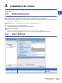
2.1
Setting Parameters . . . . . . . . . . . . . . . . . . . . . . . . . . . . . . . . . . . . . . . . . . . . . . . . . . . . . . . . . . . . . . . . . . . . . 123
2.2
Basic Settings . . . . . . . . . . . . . . . . . . . . . . . . . . . . . . . . . . . . . . . . . . . . . . . . . . . . . . . . . . . . . . . . . . . . . . . . . 123
Own Node Settings . . . . . . . . . . . . . . . . . . . . . . . . . . . . . . . . . . . . . . . . . . . . . . . . . . . . . . . . . . . . . . . . . . . . . . 124
External Device Configuration . . . . . . . . . . . . . . . . . . . . . . . . . . . . . . . . . . . . . . . . . . . . . . . . . . . . . . . . . . . . . . 126
2.3
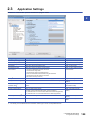
Application Settings . . . . . . . . . . . . . . . . . . . . . . . . . . . . . . . . . . . . . . . . . . . . . . . . . . . . . . . . . . . . . . . . . . . . 129
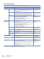
Frame Settings . . . . . . . . . . . . . . . . . . . . . . . . . . . . . . . . . . . . . . . . . . . . . . . . . . . . . . . . . . . . . . . . . . . . . . . . . 130
Communication Speed . . . . . . . . . . . . . . . . . . . . . . . . . . . . . . . . . . . . . . . . . . . . . . . . . . . . . . . . . . . . . . . . . . . 131
FTP Server Settings . . . . . . . . . . . . . . . . . . . . . . . . . . . . . . . . . . . . . . . . . . . . . . . . . . . . . . . . . . . . . . . . . . . . . 132
Time Setting . . . . . . . . . . . . . . . . . . . . . . . . . . . . . . . . . . . . . . . . . . . . . . . . . . . . . . . . . . . . . . . . . . . . . . . . . . . 133
Timer Settings for Data Communication . . . . . . . . . . . . . . . . . . . . . . . . . . . . . . . . . . . . . . . . . . . . . . . . . . . . . . 134
Security . . . . . . . . . . . . . . . . . . . . . . . . . . . . . . . . . . . . . . . . . . . . . . . . . . . . . . . . . . . . . . . . . . . . . . . . . . . . . . . 137
Gateway Parameter Settings. . . . . . . . . . . . . . . . . . . . . . . . . . . . . . . . . . . . . . . . . . . . . . . . . . . . . . . . . . . . . . . 137
Network/Station No. <-> IP information setting . . . . . . . . . . . . . . . . . . . . . . . . . . . . . . . . . . . . . . . . . . . . . . . . . 139
Interrupt Settings . . . . . . . . . . . . . . . . . . . . . . . . . . . . . . . . . . . . . . . . . . . . . . . . . . . . . . . . . . . . . . . . . . . . . . . . 146
IP Packet Transfer Setting. . . . . . . . . . . . . . . . . . . . . . . . . . . . . . . . . . . . . . . . . . . . . . . . . . . . . . . . . . . . . . . . . 146
Network Dynamic Routing . . . . . . . . . . . . . . . . . . . . . . . . . . . . . . . . . . . . . . . . . . . . . . . . . . . . . . . . . . . . . . . . . 147
Module Operation Mode . . . . . . . . . . . . . . . . . . . . . . . . . . . . . . . . . . . . . . . . . . . . . . . . . . . . . . . . . . . . . . . . . . 147
CHAPTER 3
3.1
TROUBLESHOOTING
149
Checking with LED . . . . . . . . . . . . . . . . . . . . . . . . . . . . . . . . . . . . . . . . . . . . . . . . . . . . . . . . . . . . . . . . . . . . . 149
3.2
Checking the Module Status. . . . . . . . . . . . . . . . . . . . . . . . . . . . . . . . . . . . . . . . . . . . . . . . . . . . . . . . . . . . . . 151
3.3
Checking the Network Status . . . . . . . . . . . . . . . . . . . . . . . . . . . . . . . . . . . . . . . . . . . . . . . . . . . . . . . . . . . . . 154
3.4
Troubleshooting by Symptom . . . . . . . . . . . . . . . . . . . . . . . . . . . . . . . . . . . . . . . . . . . . . . . . . . . . . . . . . . . . 161
3.5
List of Error Codes . . . . . . . . . . . . . . . . . . . . . . . . . . . . . . . . . . . . . . . . . . . . . . . . . . . . . . . . . . . . . . . . . . . . . 170
3.6
List of Parameter Numbers. . . . . . . . . . . . . . . . . . . . . . . . . . . . . . . . . . . . . . . . . . . . . . . . . . . . . . . . . . . . . . . 185
3.7
Event List . . . . . . . . . . . . . . . . . . . . . . . . . . . . . . . . . . . . . . . . . . . . . . . . . . . . . . . . . . . . . . . . . . . . . . . . . . . . . 186
3.8
End Codes Returned to an External Device During Data Communications . . . . . . . . . . . . . . . . . . . . . . . 187
11
APPENDICES
188
Appendix 1 Module Label . . . . . . . . . . . . . . . . . . . . . . . . . . . . . . . . . . . . . . . . . . . . . . . . . . . . . . . . . . . . . . . . . . . . . 188
Appendix 2 I/O Signals . . . . . . . . . . . . . . . . . . . . . . . . . . . . . . . . . . . . . . . . . . . . . . . . . . . . . . . . . . . . . . . . . . . . . . . 189
List of I/O signals . . . . . . . . . . . . . . . . . . . . . . . . . . . . . . . . . . . . . . . . . . . . . . . . . . . . . . . . . . . . . . . . . . . . . . . . 189
Appendix 3 Buffer Memory . . . . . . . . . . . . . . . . . . . . . . . . . . . . . . . . . . . . . . . . . . . . . . . . . . . . . . . . . . . . . . . . . . . . 191
List of buffer memory addresses . . . . . . . . . . . . . . . . . . . . . . . . . . . . . . . . . . . . . . . . . . . . . . . . . . . . . . . . . . . . 191
Details of buffer memory addresses . . . . . . . . . . . . . . . . . . . . . . . . . . . . . . . . . . . . . . . . . . . . . . . . . . . . . . . . . 206
Appendix 4 Dedicated Instruction . . . . . . . . . . . . . . . . . . . . . . . . . . . . . . . . . . . . . . . . . . . . . . . . . . . . . . . . . . . . . . 216
Precautions for dedicated instructions. . . . . . . . . . . . . . . . . . . . . . . . . . . . . . . . . . . . . . . . . . . . . . . . . . . . . . . . 217
Appendix 5 TCP/IP Communications, UDP/IP Communications . . . . . . . . . . . . . . . . . . . . . . . . . . . . . . . . . . . . . . 218
TCP/IP communications . . . . . . . . . . . . . . . . . . . . . . . . . . . . . . . . . . . . . . . . . . . . . . . . . . . . . . . . . . . . . . . . . . 218
UDP/IP communications . . . . . . . . . . . . . . . . . . . . . . . . . . . . . . . . . . . . . . . . . . . . . . . . . . . . . . . . . . . . . . . . . . 223
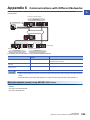
Appendix 6 Communications with Different Networks. . . . . . . . . . . . . . . . . . . . . . . . . . . . . . . . . . . . . . . . . . . . . . 225
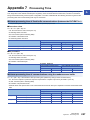
Appendix 7 Processing Time . . . . . . . . . . . . . . . . . . . . . . . . . . . . . . . . . . . . . . . . . . . . . . . . . . . . . . . . . . . . . . . . . . 227
Appendix 8 Port Numbers Used by Ethernet-equipped Module . . . . . . . . . . . . . . . . . . . . . . . . . . . . . . . . . . . . . . 228
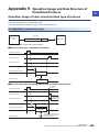
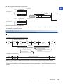
Appendix 9 Operation Image and Data Structure of Predefined Protocol . . . . . . . . . . . . . . . . . . . . . . . . . . . . . . 229
Operation image of each communication type of protocol . . . . . . . . . . . . . . . . . . . . . . . . . . . . . . . . . . . . . . . . 229
Verification operation of receive packet. . . . . . . . . . . . . . . . . . . . . . . . . . . . . . . . . . . . . . . . . . . . . . . . . . . . . . . 234
Example of packet element data . . . . . . . . . . . . . . . . . . . . . . . . . . . . . . . . . . . . . . . . . . . . . . . . . . . . . . . . . . . . 235
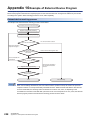
Appendix 10Example of External Device Program . . . . . . . . . . . . . . . . . . . . . . . . . . . . . . . . . . . . . . . . . . . . . . . . . 238
Appendix 11 Added and Enhanced Functions . . . . . . . . . . . . . . . . . . . . . . . . . . . . . . . . . . . . . . . . . . . . . . . . . . . . . 239
INDEX
240
REVISIONS . . . . . . . . . . . . . . . . . . . . . . . . . . . . . . . . . . . . . . . . . . . . . . . . . . . . . . . . . . . . . . . . . . . . . . . . . . . . .242
WARRANTY . . . . . . . . . . . . . . . . . . . . . . . . . . . . . . . . . . . . . . . . . . . . . . . . . . . . . . . . . . . . . . . . . . . . . . . . . . . .243
TRADEMARKS . . . . . . . . . . . . . . . . . . . . . . . . . . . . . . . . . . . . . . . . . . . . . . . . . . . . . . . . . . . . . . . . . . . . . . . . . .244
12
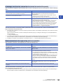
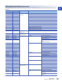
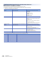
RELEVANT MANUALS
Manual name [manual number]
Description
Available form
MELSEC iQ-R Ethernet User's Manual (Application)
[SH-081257ENG] (this manual)
Functions, parameter settings, programming, troubleshooting, I/O
signals, and buffer memory of Ethernet
Print book
MELSEC iQ-R Ethernet/CC-Link IE User's Manual (Startup)
[SH-081256ENG]
Specifications, procedures before operation, system configuration,
wiring, and communication examples of Ethernet, CC-Link IE
Controller Network, and CC-Link IE Field Network
Print book
MELSEC iQ-R CPU Module User's Manual (Startup)
[SH-081263ENG]
Performance specifications, procedures before operation, and
troubleshooting of the CPU module
Print book
MELSEC iQ-R Programming Manual (Instructions, Standard
Functions/Function Blocks)
[SH-081266ENG]
Instructions for the CPU module, link dedicated instructions,
socket communications/fixed buffer communications instructions
e-Manual
EPUB
PDF
SLMP Reference Manual
[SH-080956ENG]
The protocol (SLMP) used for data reading or writing from an
external device to the Ethernet-equipped module
Print book
iQ Sensor Solution Reference Manual
[SH-081133ENG]
Operating methods of iQ Sensor Solution, such as programming
and monitoring
Print book
e-Manual
EPUB
PDF
e-Manual
EPUB
PDF
e-Manual
EPUB
PDF
e-Manual
EPUB
PDF
e-Manual
EPUB
PDF
This manual does not include information on the module function blocks.
For details, refer to the Function Block Reference for the module used.
e-Manual refers to the Mitsubishi FA electronic book manuals that can be browsed using a dedicated tool.
e-Manual has the following features:
• Required information can be cross-searched in multiple manuals.
• Other manuals can be accessed from the links in the manual.
• The hardware specifications of each part can be found from the product figures.
• Pages that users often browse can be bookmarked.
13
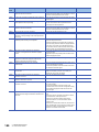
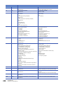
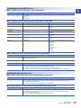
TERMS
Unless otherwise specified, this manual uses the following terms.
14
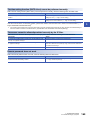
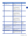
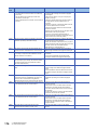
Term
Description
ARP
The abbreviation for Address Resolution Protocol. This protocol is used to obtain the MAC address of
Ethernet from an IP address.
Buffer memory
A memory in an intelligent function module, where data (such as setting values and monitoring values)
are stored. When using the CPU module, the memory is indicated for storing data (such as setting
values and monitored values) of the Ethernet function and data used for data communication of the
multiple CPU function.
BUFRCV
A generic term for the GP.BUFRCV and ZP.BUFRCV
BUFRCVS
A generic term for the G.BUFRCVS and Z.BUFRCVS
BUFSND
A generic term for the GP.BUFSND and ZP.BUFSND
CLOSE
A generic term for the GP.CLOSE and ZP.CLOSE
Control CPU
A CPU module that controls connected I/O modules and intelligent function modules.
In a multiple CPU system, there are multiple CPU modules and each connected module can be
controlled by a different CPU module.
CPU module
A generic term for the MELSEC iQ-R series CPU module
CPU module (built-in Ethernet port part)
A built-in Ethernet port part of the CPU module (CPU part for the RnENCPU) ( MELSEC iQ-R
Ethernet/CC-Link IE User's Manual (Startup))
Dedicated instruction
An instruction for using functions of the module
Device
A device (X, Y, M, D, or others) in a CPU module
Device supporting iQSS
A generic term for a device which supports iQ Sensor Solution
For details on iQ Sensor Solution, refer to the following.
iQ Sensor Solution Reference Manual
Engineering tool
Another term for the software package for the MELSEC programmable controllers
ERRCLEAR
A generic term for the GP.ERRCLEAR and ZP.ERRCLEAR
ERRRD
A generic term for the GP.ERRRD and ZP.ERRRD
Ethernet device
A generic term for the devices supporting IP communication (such as personal computers)
Ethernet-equipped module
A generic term for the following modules when the Ethernet function is used:
• RJ71EN71
• CPU module
External device
A generic term for personal computers connected with Ethernet for data communication and other
Ethernet-equipped modules
FTP
The abbreviation for File Transfer Protocol. This protocol is used to transfer data files over a network.
Global label
A label that is enabled for all program data when creating multiple program data in the project.
There are two types of global labels: module label that is automatically generated by GX Works3 and
label that can be created for the any of the specified devices.
ICMP
The abbreviation for Internet Control Message Protocol. This protocol is used to exchange messages of
errors in an IP network or other information related to an Ethernet network.
Intelligent function module
A module that has functions other than input and output, such as an A/D converter module and D/A
converter module
Label
A label that represents a device in a given character string
MELSECNET/10
The abbreviation for the MELSECNET/10 network system
MELSECNET/H
The abbreviation for the MELSECNET/H network system
Module label
A label that represents one of memory areas (I/O signals and buffer memory areas) specific to each
module in a given character string.
GX Works3 automatically generates this label, which can be used as a global label.
Network module
A generic term for the following modules:
• Ethernet interface module
• CC-Link IE Controller Network module
• Module on CC-Link IE Field Network
• MELSECNET/H network module
• MELSECNET/10 network module
• RnENCPU (network part)
OPEN
A generic term for the GP.OPEN and ZP.OPEN
Predefined protocol support function
A function of GX Works3.
This function sets protocols appropriate to each external device and reads/writes protocol setting data.
READ
A generic term for the JP.READ and GP.READ
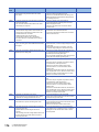
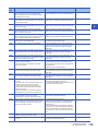
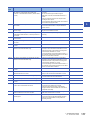
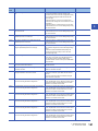
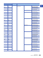
Term
Description
RECV
A generic term for the JP.RECV and GP.RECV
RECVS
A generic term for the G.RECVS and Z.RECVS
Relay station
A station that includes two or more network modules. Transient transmission is performed through this
station to stations on other networks
REQ
A generic term for the J.REQ, JP.REQ, G.REQ, and GP.REQ
RnENCPU
A generic term for the R04ENCPU, R08ENCPU, R16ENCPU, R32ENCPU, and R120ENCPU
RnENCPU (CPU part)
The left side (CPU part) of the RnENCPU ( MELSEC iQ-R Ethernet/CC-Link IE User's Manual
(Startup))
RnENCPU (network part)
The right side (network part) of the RnENCPU ( MELSEC iQ-R Ethernet/CC-Link IE User's Manual
(Startup))
Routing
A process of selecting paths for communication with other networks. There are two types of routing:
dynamic routing that auto-selects the communication paths, and static routing where desired
communication paths are set.
Safety CPU
A generic term for the R08SFCPU, R16SFCPU, R32SFCPU, and R120SFCPU
Seamless communication
Communication that allows users to access a different kind of networks without having to consider the
differences as if data were exchanged within one single network
SEND
A generic term for the JP.SEND and GP.SEND
SLMP
The abbreviation for Seamless Message Protocol.
This protocol is used to access an SLMP-compatible device or a programmable controller connected to
an SLMP-compatible device from an external device.
SREAD
A generic term for the JP.SREAD and GP.SREAD
Subnet mask
A number used to logically divide one network into multiple subnetworks and manage them easily. The
following Ethernet network systems can be configured:
• A small-scale Ethernet network system in which multiple network devices are connected
• A medium- or large-scale network system in which multiple small-scale network systems are
connected via routers or other network communication devices
SWRITE
A generic term for the JP.SWRITE and GP.SWRITE
Transient transmission group number
Number that is assigned for transient transmission to any given stations.
By specifying a group of stations as transient transmission target, data can be sent to the stations of the
same group number.
UINI
A generic term for the G.UINI, GP.UINI, Z.UINI, and ZP.UINI
WRITE
A generic term for the JP.WRITE and GP.WRITE
ZNRD
A generic term for the J.ZNRD and JP.ZNRD
ZNWR
A generic term for the J.ZNWR and JP.ZNWR
15
1
FUNCTIONS
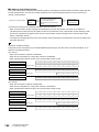
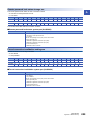
1.1
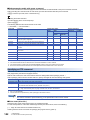
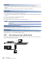
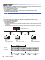
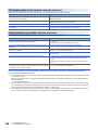
Connection with MELSOFT Product and GOT
Programming and monitoring of the programmable controller with the engineering tool, and monitoring and testing of the
programmable controller from the GOT can be performed via Ethernet. This function enables remote operations using
Ethernet's long-distance connection and high-speed communication.
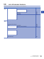
The section describes the methods of connecting the Ethernet-equipped module, MELSOFT product (such as engineering
tool and MX Component), and GOT.
: Connection available, : Connection not available
Connection method
Purpose
Availability
MELSOFT products
GOT
RJ71EN71,
RnENCPU
(network
part)
CPU module
(built-in
Ethernet port
part)
RJ71EN71,
RnENCPU
(network
part)
CPU module
(built-in
Ethernet port
part)
Connection via a hub
(Connection by specifying the IP
address)
• To connect to an Ethernet-equipped
module that has no network number and
station number
• To connect multiple MELSOFT products
Connection via a hub
(Connection by specifying the
network number and station
number)
• To connect by using network number and
station number
• To connect multiple MELSOFT products
and GOTs
Direct connection
(Connection without specifying the
IP address, network number, or
station number)*1
• To connect without hub using one
Ethernet cable for one-on-one
communication with the external device
• To connect to an Ethernet-equipped
module whose IP address in unknown
*1
This connection method is not available when the RJ71EN71 network type is set to "Q Compatible Ethernet".
For the procedures to connect the Ethernet-equipped module and GOT, refer to the following.
Manual for the GOT used
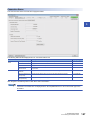
Connection via a hub
Setting procedure
■Setting in the Ethernet-equipped module side
Set the IP address of the Ethernet-equipped module in "Own Node Settings" under "Basic Settings". ( Page 124 Own
Node Settings)
When connecting by specifying the network number and station number, set the network number and station number in "Own
Node Settings" under "Basic Settings".
Even if "External Device Configuration" is not set under "Basic Settings", the Ethernet-equipped module can be connected to
the MELSOFT product and GOT using the system dedicated connection. *1
*1
When using a TCP/IP connection with the system dedicated connection, up to ((maximum number of connected modules in "External
Device Configuration") - (set number) + 1) modules can be connected.
When using a UDP/IP connection, up to the maximum number of connectable modules can be connected.
When connecting multiple MELSOFT products with TCP/IP, drag "MELSOFT Connection Module" from the
"Module List" to "List of devices" or "Device map area" in "External Device Configuration" under "Basic
Settings". ( Page 126 External Device Configuration)
16
1 FUNCTIONS
1.1 Connection with MELSOFT Product and GOT
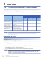
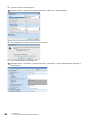
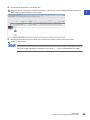
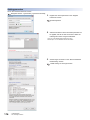
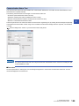
■Settings on the engineering tool side
Set with "Specify Connection Destination".
1
[Online] [Specify Connection Destination]
1.
2.
3.
Set "PC side I/F" to "Ethernet Board".
Double-click "Ethernet Board", and open the "PC side I/
F Detailed Setting of Ethernet board" window.
Set the network number, station number, and protocol of
the personal computer. (Set the network number and
protocol according to the settings for the Ethernetequipped module. Set the station number so that it is not
the same as a station number assigned to other
Ethernet devices.)*1
4.
Set the "PLC side I/F" to the module to be connected.
1 FUNCTIONS
1.1 Connection with MELSOFT Product and GOT
17
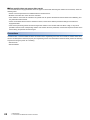
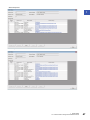
5.
6.
Double-click the icon set in step 4, and open the "PLC
side I/F Detailed Setting" window.
Select "Connection via HUB" for the connection method,
and enter the station number and IP address or host
name for the Ethernet-equipped module. Select
"RJ71EN71" to connect the RnENCPU (network part).
7.
Set "Other Station Setting" or "Network Communication
Route" if necessary.
*1
18
The network number and station number do not need to be set when connecting with the CPU module (built-in Ethernet port part).
1 FUNCTIONS
1.1 Connection with MELSOFT Product and GOT
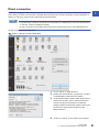
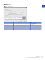
Searching modules on the network
1
When connecting with a hub, a list of modules that can be searched for will appear by clicking the [Find] button on the "PLC
side I/F Detailed Setting" window.
■Search target modules
• The control CPU of the RJ71EN71 or the CPU module connected to the same hub as the engineering tool
• The control CPU of the RJ71EN71 or the CPU module connected to cascade-connected hub
• By setting "Not Respond to Network CPU Module Search" in "Security" under "Application Settings" to "Do
Not Respond", the modules will not be listed even if a search is performed.
• Only the MELSEC iQ-R Series Ethernet-equipped modules are searched.
• The RJ71EN71 in which the network type is set to "Q Compatible Ethernet" cannot be searched.
1 FUNCTIONS
1.1 Connection with MELSOFT Product and GOT
19
■When module does not appear after search
If a connected Ethernet-equipped module does not appear in the list after searching the modules on the network, check the
following items.
• Search cannot be performed if it is disabled with the IP filter function.
• Modules connected via a router cannot be searched.
• If the module is connected via a wireless LAN, packet loss can prevent the Ethernet communication from stabilizing, and
may inhibit the module search.
• If there are modules with the same IP address in the list, review the IP address parameter settings for the Ethernetequipped module.
• If the service processing load of the search-target CPU module or CPU module with RJ71EN71 is high, it may not be
possible to search for the corresponding module. If the search cannot be performed, increase the response wait time in the
search dialog, and perform the search again.
Precautions
If remote STOP or remote PAUSE has been executed from the engineering tool to the CPU module on another station when
the CPU module (built-in Ethernet port part) and engineering tool are connected with an Ethernet cable, perform the following
step before turning the power off or resetting.
• Remote RUN
• Remote RESET
20
1 FUNCTIONS
1.1 Connection with MELSOFT Product and GOT
Direct connection
1
The Ethernet-equipped module and engineering tool can be directly connected with one Ethernet cable without using a hub.
When directly connected, communication is possible without specifying the connection destination or without setting the IP
address or host name. (Communicate using broadcast communications)
• To prohibit direct connection with the Ethernet, set "Disable" for "Disable Direct Connection with MELSOFT"
in "Security" under the "Application Settings".
• A direct connection is not possible when the RJ71EN71 network type is set to "Q Compatible Ethernet".
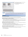
Set with "Specify Connection Destination".
[Online] [Specify Connection Destination]
1.
2.
3.
Set "PC side I/F" to "Ethernet Board".
Double-click "Ethernet Board", and open the "PC side I/
F Detailed Setting of Ethernet board" window.
Set the network number, station number, and protocol of
the personal computer. (Set the network number and
protocol according to the settings for the Ethernetequipped module. Set the station number so that it is not
the same as a station number assigned to other
Ethernet devices.)
4.
Set the "PLC side I/F" to the module to be connected.
1 FUNCTIONS
1.1 Connection with MELSOFT Product and GOT
21
5.
6.
Double-click the icon set in step 4, and open the "PLC
side I/F Detailed Setting" window.
Select "Ethernet Port Direct Connection" for the
connection method.
When connecting directly with the CPU module (built-in Ethernet port part), setting is also possible by clicking
the [CPU Module Direct Coupled Setting] button on the "Specify Connection Destination" window.
Precautions
■Connection with LAN line
Do not connect with a LAN line and set direct connection. Data will be sent to all external devices on the LAN line, so this
setting will cause the line load to increase and will affect communication with other external devices.
■Connections that are not direct connections
• Do not use a configuration in which the Ethernet-equipped module and external device are connected with a hub. A direct
connection is not established when the devices are connected with a hub.
• When creating a network connection on the personal computer side, communication with a direct connection is not possible
if two or more Ethernet ports are set to "Enable". Review the personal computer settings so that only the Ethernet port for
the direct connection is set to "Enable", and the other Ethernet ports are set to "Disable".
■Settings incompatible with direct connection
When using the RJ71EN71 or the RnENCPU (network part), a direct connection cannot be established if the following setting
is made with "Specify Connection Destination" of the engineering tool.
• When "Other Station (Co-existence Network)" is selected for "Other Station Setting"
• When "Other Station (Single Network)" is selected for "Other Station Setting", and "Other station in the same loop or access
to multilevel system" is selected in the "Network Communication Route Detailed Setting of Ethernet" window
■Functions incompatible with direct connection
The following functions cannot be used when the RJ71EN71 or the RnENCPU (network part) is directly connected. To use the
following functions, connect the CPU module (built-in Ethernet port part) directly or with a USB cable.
• CC-Link IE Field Diagnostics
• CC-Link IE Control Diagnostics
22
1 FUNCTIONS
1.1 Connection with MELSOFT Product and GOT
■Conditions that cannot communicate with direct connection
Communication with a direct connection may be disabled if the following conditions apply. If connection is not possible, review
1
the settings for the Ethernet-equipped module and personal computer.
• When all bits of the IP address for the Ethernet-equipped module that correspond with the 0 section of the subnet mask for
the personal computer are on or off
Ex.
IP address for the Ethernet-equipped module: 64.64.255.255
IP address for the personal computer: 64.64.1.1
Subnet mask for the personal computer: 255.255.0.0
• When all bits of the IP address for the Ethernet-equipped module that correspond with the host address of each class in the
IP address for the personal computer are on or off
Ex.
IP address for the personal computer: 192.168.0.1 192.x.x.x., class C and the host address is the fourth octet.
Subnet mask for the personal computer: 255.0.0.0
IP address for the Ethernet-equipped module: 64.64.255.255 each bit turns on because of the fourth octet is 255
The IP address for each class are as follow.
• Class A: 0.x.x.x to 127.x.x.x
• Class B: 128.x.x.x to 191.x.x.x
• Class C: 192.x.x.x to 223.x.x.x
The host address for each class is the 0 section shown below.
• Class A: 255.0.0.0
• Class B: 255.255.0.0
• Class C: 255.255.255.0
1.2
SLMP Communications
SLMP is a protocol used by external devices to access SLMP-compatible devices via the Ethernet.
SLMP communications are available among devices that can receive/send messages with the SLMP control procedure.
The Ethernet-equipped module processes and transfers data following instructions (command) from the external device, so
the programmable controller only needs the open/close processing and does not require a program for data communication.
For SLMP communications, refer to the following.
SLMP Reference Manual
Applications
This section describes the applications of SLMP communications.
Data read/write
Data read/write can be executed for the following data. With this, the external device can monitor the operation of the
Ethernet-equipped module, analyze data, and control production.
• Device or global label of the CPU module connected with the RJ71EN71 (When the Ethernet function of the RJ71EN71 or
the RnENCPU (network part) is used)
• Device or global label of the CPU module (When the Ethernet function of the CPU module (CPU part for the RnENCPU) is
used)
• Buffer memory of the intelligent function module
File read/write
Files such as programs and parameters stored in the CPU module can be read/written. The CPU module files can be
managed with the external device, the execution file and others can be exchanged from the external device.
1 FUNCTIONS
1.2 SLMP Communications
23
Remote control of a CPU module
A CPU module can be remotely controlled from the external device using remote operations.
Remote password lock/unlock
The remote password can be locked and unlocked from the external device.
Access to the programmable controller on another station via other network
In systems with CC-Link IE Controller Network, CC-Link IE Field Network, MELSECNET/H, MELSECNET/10 or Ethernet, the
programmable controller on another station can be accessed from the external device via the network.
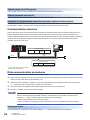
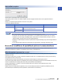
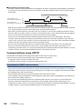
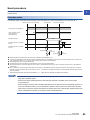
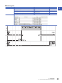
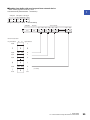
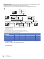
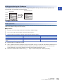
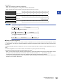
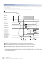
Communication structure
When a message is sent from the external device to the Ethernet-equipped module using the SLMP message format, the
Ethernet-equipped module executes a processing corresponding to the received message. During communication, the
Ethernet-equipped module functions as a server and the external device (terminals such as a personal computer) functions as
the client. The server (Ethernet-equipped module) automatically returns a response message suitable for the request
message received from the client.
(2)
(1)
Request message
Header
Subheader
Access
destination
Command
Ethernet
Response message
Header
Subheader
Response data
(1) Server side: Ethernet-equipped module
(2) Client side: External device
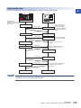
Data communication procedures
This section describes the procedures for communicating with SLMP.
1.
After the module parameters are set, the system checks that the initial processing of the Ethernet-equipped module has
ended normally. ('Initial status' (Un\G1900024.0): On)
2.
Perform the open processing to establish a connection between the Ethernet-equipped module and external device.
( Page 218 TCP/IP Communications, UDP/IP Communications)
3.
4.
After the connection is established, the SLMP messages are sent from the external device.
Close the connection when communication is finished.
In the following case, the Ethernet-equipped module performs a remote password check when the external
device is accessing the programmable controller. If communication is not possible, unlock the remote
password. ( Page 115 Access permit processing (Unlock processing))
• When remote password is set for the CPU module
• When connection for exchanging data with external device is set as a remote password check target
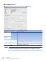
Setting procedure
Set "External Device Configuration" under "Basic Settings". ( Page 126 External Device Configuration)
24
1 FUNCTIONS
1.2 SLMP Communications
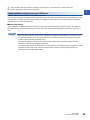
1.
2.
Select "SLMP Connection Module" in "Module List" and drag it to "List of devices" or "Device map area".
Set the other items to the connection if required.
1
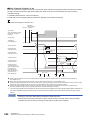
Communications using an auto-open UDP port
The auto-open UDP port is used for communication with SLMP.
The auto-open UDP port is a UDP/IP port that automatically opens and closes at the following timing. When this port is used,
communication is enabled when the initial processing is completed. Communication can be performed without a program
regardless of the connection's open status
■Open/close timing
After the Ethernet-equipped module initial processing completes, the port automatically opens according to the registered
parameter settings. The port automatically closes when the power for the Ethernet-equipped module station turns off or is
reset.
• When the initial processing ends normally, the Ethernet-equipped module enables communications using
an automatic open UDP port. The module waits for a communication request to the Ethernet-equipped
module on the own station. (Automatic open)
• The Ethernet-equipped module accepts and processes requests from anywhere as long as they are
addressed to the Ethernet-equipped module itself.
• If a communication request is received from an external device, the corresponding port number is occupied
until that processing ends. Even if another communication request is accepted during this time, the
communication processing will be waited.
1 FUNCTIONS
1.2 SLMP Communications
25
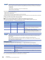
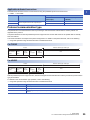
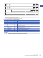
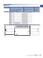
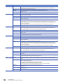
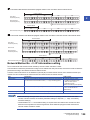
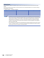
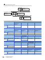
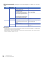
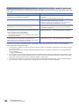
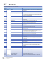
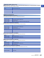
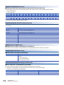
List of valid commands
The following table lists the commands that can be executed from the external device to the Ethernet-equipped module.
"" in the "Sub-command" field differs according to the specified device.
For details on each command, refer to the following.
SLMP Reference Manual
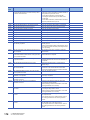
Item
Type
Operation
Device
Read
Command
Sub
command
Description
0401
001
Reads value from the bit devices (consecutive device No.) in one-point units.
000
003
002
Write
1401
001
000
003
002
Read Random
Write Random
Entry Monitor
Device
0403
1402
0801
• Writes value to the bit devices (consecutive device No.) in 16-point units.
• Writes value to the word devices (consecutive device No.) in one-word units.
Writes value to the bit devices (consecutive device No.) in one-point units.
• Writes value to the bit devices (consecutive device No.) in 16-point units.
• Writes value to the word devices (consecutive device No.) in one-word units.
Writes value to the bit devices (consecutive device No.) in one-point units.
• Writes value to the bit devices (consecutive device No.) in 16-point units.
• Writes value to the word devices (consecutive device No.) in one-word units.
Specifies the device number and reads value from the word devices in one-word units
or two-word units. This can be specified with inconsecutive device No.
002
Specifies the device number and reads value from the word devices in one-word units
or two-word units. This can be specified with inconsecutive device No.
001
Specifies the device No. to bit device in one-point units and writes value. This can be
specified with inconsecutive device No.
000
• Specifies the device No. to bit device in 16-point units and writes value. This can be
specified with inconsecutive device No.
• Specifies the device No. to word device in one-word units or two-word units and
writes value. This can be specified with inconsecutive device No.
003
Specifies the device No. to bit device in one-point units and writes value. This can be
specified with inconsecutive device No.
002
• Specifies the device No. to bit device in 16-point units and writes value. This can be
specified with inconsecutive device No.
• Specifies the device No. to word device in one-word units or two-word units and
writes value. This can be specified with inconsecutive device No.
000
Registers the device to be read by Execute Monitor (command: 0802).
002
Execute Monitor
0802
0000
Reads the value of device registered by Entry Monitor Device (command: 0801).
Read Block
0406
000
Reads data by treating n points of word devices or bit devices (one point is equivalent
to 16 bits) as one block and specifying multiple blocks. This can be specified with
inconsecutive device No.
Write Block
1406
000
002
26
Writes value to the bit devices (consecutive device No.) in one-point units.
000
002
Label
• Reads values from the bit device (consecutive device No.) in 16-point units.
• Reads value from the word devices (consecutive device No.) in one-word units.
Writes data by treating n points of word devices or bit devices (one point is equivalent
to 16 bits) as one block and specifying multiple blocks. This can be specified with
inconsecutive device No.
Array Label Read
041A
0000
Reads data from array type labels or labels whose structure members are the array.
Array Label Write
141A
0000
Writes data to array type labels or labels whose and structure members are the array.
Read Random
041C
0000
Specifies labels and reads the data.
Write Random
141B
0000
Specifies labels and writes data.
Memory
Read
0613
0000
Reads the buffer memory data of own station (SLMP-compatible device).
Write
1613
0000
Writes the data in the buffer memory of own station (SLMP-compatible device).
Extend Unit
Read
0601
0000
Reads the data in the buffer memory of intelligent function module.
Write
1601
0000
Writes the data in the buffer memory of intelligent function module.
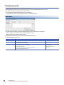
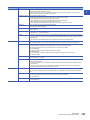
1 FUNCTIONS
1.2 SLMP Communications
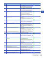
Item
Command
Sub
command
Description
Remote Run
1001
0000
Executes the remote RUN to the access destination module.
Remote Stop
1002
0000
Executes the remote STOP to the access destination module.
Remote Pause
1003
0000
Executes the remote PAUSE to the access destination module.
Remote Latch
Clear
1005
0000
Executes the Remote Latch Clear to the access destination module.
Executes the Remote RESET to the access destination module.
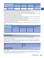
Type
Operation
Remote Control
Remote
Password
File
Self Test
Remote Reset
1006
0000
Read Type Name
0101
0000
Reads the model name and model code of the access destination module.
Lock
1631
0000
Specifies the remote password to disable the communication with other devices.
(The locked state is activated from the unlocked state.)
Unlock
1630
0000
Specifies the remote password to enable communication with other devices.
(The unlocked state is activated from the locked state.)
Read Directory/
File
1810
0040
Reads file list information.
Search Directory/
File
1811
0040
Reads the presence of the specified file, file No., and file size.
New File
1820
0040
Reserves storage area for the specified file.
Delete File
1822
0040
Deletes a file.
Copy File
1824
0040
Copies the specified file.
Change File
State
1825
0040
Changes file attributes.
Change File Date
1826
0040
Changes the file creation date.
Open File
1827
0040
Locks a file so that the content of the file is not changed by other devices.
Read File
1828
0000
Reads the data of a file.
Write File
1829
0000
Writes the contents in a file.
Close File
182A
0000
Cancels the file lock by open processing.
0619
0000
Tests whether the communication with external devices is normally executed or not.
1 FUNCTIONS
1.2 SLMP Communications
1
27
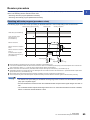
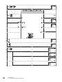
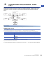
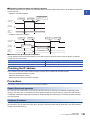
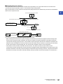
1.3
Communications Using the Predefined Protocol
Data can be exchanged between the external device (such as measuring instrument and bar code reader) and the CPU
module following the protocol of the device.
Data that varies according to communication session can be handled by incorporating a device or buffer memory into the
communication packet.
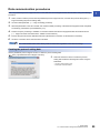
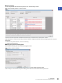
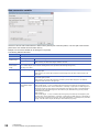
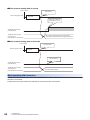
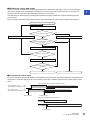
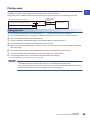
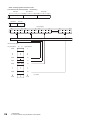
Sets the protocol required for communication with the external device using the engineering tool.
The protocol can be set by selecting from the predefined protocol library, or it can be created and edited.
Ò Setting protocols
Ó Writing protocols
Protocols can be set easily using the predefined
protocol support function of GX Works3.
Write the set protocols in the Ethernet-equipped module.
GX Works3
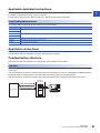
Sending
External device
Ethernet-equipped module
External device
Receiving
Ô Executing protocols
Data can be communicated
with protocols appropriate
to each external device.
Execute protocols by dedicated instructions.
Multiple protocols can be executed by one dedicated instruction.
The number of protocols and packets that can be registered is as follow.
• Protocols: 128 maximum
• Packets: 256 maximum
• Packet data area size: 12288 bytes maximum
When the number of packets reaches the upper limit, protocols cannot be added even if the number of
protocols has not reached the upper limit. If the packet data area size reaches the upper limit, protocols and
packets cannot be added even if the number of protocols and packets has not reached the upper limit.
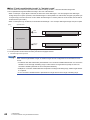
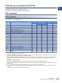
Applicable connections
The connections No.1 to 16 of the P1 connector can be used for the communications using the predefined protocol.
Communications using the predefined protocol cannot be used with the P2 connector.
28
1 FUNCTIONS
1.3 Communications Using the Predefined Protocol
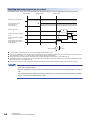
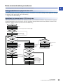
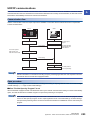
Data communication procedures
1
When the predefined protocol support function is used, data can be exchanged with the external device using the following
procedure.
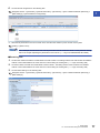
1.
Select, create or edit the protocol with the predefined protocol support function, and write the protocol setting data. (
Page 29 Creating the protocol setting data)
2.
3.
Set the module parameter. ( Page 34 Setting procedure)
Write the parameters to the CPU module, and check that initial processing of the Ethernet-equipped module completed
successfully. ('Initial status' (Un\G1900024.0): On)
4.
Perform the open processing to establish a connection between the Ethernet-equipped module and external device.
( Page 218 TCP/IP Communications, UDP/IP Communications)
5.
6.
Execute the protocol with the dedicated instruction (SP.ECPRTCL instruction or GP.ECPRTCL instruction).
Close the connection when communication is finished.
The communication data code is binary code communication regardless of the selected settings.
Creating the protocol setting data
Use the predefined protocol support function to create the protocol setting data.
[Tool] [Predefined Protocol Support Function]
1.
Select the module for which to create the protocol
setting data. Select the following items when using the
RnENCPU.
• CPU part: "Built-in Ethernet CPU"
• Network part: "Ethernet Module"
1 FUNCTIONS
1.3 Communications Using the Predefined Protocol
29
■Newly creating the protocol setting data
Newly create the protocol setting data.
[File] [New]
Item
30
Description
Protocol No.
Displays the protocol number used with the dedicated instruction in the program.
Manufacturer
Displays the name of the manufacturer of the device for which the protocol is being set.
Model
Displays the model of the protocol to be set.
Protocol Name
Displays the name of the protocol to be set.
Communication Type
Displays the communication type of the protocol to be set.
Send only: Sends one send packet once.
Receive only: If there is a matching packet within up to 16 registered and received packets, it is received.
Send & receive: After sending one send packet, if there is a matching packet within up to 16 registered and received
packets, it is received.
Send/Receive
Displays the packet send direction.
: For send
(1) to (16): For receive, the received packet number is displayed in parentheses.
Packet Name
Displays the packet name.
Packet Setting
Displays the validity of variables in the packet elements and the variable setting state.
If the variable is not set, there are no elements, or there is an element error, the protocol is not written to the Ethernetequipped module.
No Variable: When there is no variable in the elements
Variable Set: Only when all variables have been set
Variable Unset: When there is even one unset variable
Elements Unset: When there are no elements in an editable protocol
Element Error: When elements do not satisfy requirements
1 FUNCTIONS
1.3 Communications Using the Predefined Protocol
■Adding protocol
Add protocol.
1
[Edit] [Add Protocol]
Item
Description
Type
Select the type of protocol to be added.
Protocol No.
Select the protocol number to be added.
1 to 128
Manufacturer*1
Set the maker of the protocol to be added.
Model*1
Set the type of protocol to be added.
Protocol Name*1
Set the name of the protocol to be added.
*1
Setting range
• Predefined Protocol Library
• User Protocol Library
• Add New
The name can be set only when "Predefined Protocol Library" is selected for "Type"
1 FUNCTIONS
1.3 Communications Using the Predefined Protocol
31
■Protocol Detailed Setting
Set the protocol send/receive parameters.
"Protocol Setting" window Select a protocol [Edit] [Protocol Detailed Setting]
Item
Description
Connected Device
Information*1
Protocol setting
information*1
Manufacturer
Set the protocol maker name.
Type
Set the protocol device type.
Model
Set the protocol model.
Version
Set the protocol device version.
Description
Set a description of the protocol device.
Protocol No.
The protocol number for the selected protocol is displayed.
Protocol Name
Set the protocol name.
Communication Type
Set the protocol communication type.
Receive Setting
Receive Wait Time
Set the time for wait after the module enters the receive data wait state.
If communication with the external device is disabled because of a disconnection and matching packet
data is not received within the specified time, the module judges that an error has occurred and cancels
the receive data wait state.
Send Setting
Send Wait Time
Set the time to wait from when the protocol set for the module enters the execution state to when the
data is actually sent. The time for the external device to enter the receive enable state can be adjusted
with this in respect to the module's send timing.
*1
The setting cannot be changed if the protocol was selected from the predefined protocol library.
Send/receive parameters can be set for multiple protocols by clicking the [Communication Parameter Batch
Setting] button and setting the range of the set protocol numbers, receive settings, and send settings.
32
1 FUNCTIONS
1.3 Communications Using the Predefined Protocol
■Packet setting
Set the configuration of the send/receive packets on the "Packet Setting" window.
1
"Protocol Setting" window Packet to be set
The above window opens when "Predefined Protocol Library" is selected on the "Add Protocol" window.
When "Add New" or "User Protocol Library" has been selected, configure the packets with the [Change Type] button and [Add
New] button.
For details on the packet elements, refer to the following.
Page 36 Packet elements
■Writing the protocol setting data
Write the protocol setting data to the Ethernet-equipped module.
[Online] [Write to Module]
Select the module and memory into which the protocol data is to be written, and execute write.
When writing to a CPU module, the protocol setting data is written into the module extension parameters.
1 FUNCTIONS
1.3 Communications Using the Predefined Protocol
33
The following data is not written as the protocol setting data so it will not be displayed even when read.
However, when the protocol is selected from the predefined protocol library, the following can be displayed.
• Manufacturer
• Packet name
• Type, version, and explanation in the protocol detailed setting
• Element name in packet settings
After writing the protocol setting data, the setting data are enabled at the following timing.
• When the system is powered off and on
• When the CPU module is reset
• When the status of the CPU module changed from STOP to RUN state
The predefined protocol settings written in the SD memory card can be transferred to the CPU module memory by using boot
operation. For details on boot operation, refer to the following.
MELSEC iQ-R CPU Module User's Manual (Application)
■When the protocol setting data are written into multiple target memories
When the protocol setting data are written into multiple target memories, the following operation will take place.
: The protocol setting data are written., : The predefined protocol data are not written.
Target memory
Operation
CPU module (built-in
Ethernet port part)
SD memory card
RJ71EN71,
RnENCPU (network
part)
Operation follows settings in "Memory Card Parameter".
As soon as the protocol setting data are enabled, the predefined protocol
settings of the RJ71EN71 or the RnENCPU (network part) are
overwritten by the predefined protocol settings in the CPU module or SD
memory card.
Operation follows settings in "Memory Card Parameter".
As soon as the protocol setting data are enabled, the predefined protocol
settings of the RJ71EN71 or the RnENCPU (network part) are
overwritten by the predefined protocol settings in the CPU module or SD
memory card.
By writing the protocol setting data to the CPU built-in memory, the same setting can be used even after
module change.
When capacity of the CPU built-in memory is insufficient, write data to an SD memory card.
Although the protocol setting data can also be written to the intelligent function module, the data must be
written again when the module is changed.
Setting procedure
Set "External Device Configuration" under "Basic Settings". ( Page 126 External Device Configuration)
1.
External device name
Description
UDP Connection Module
Select to communicate with the external device using UDP/IP
Active Connection Module
Select to perform the open processing to the external device from the Ethernet-equipped module (Active open)
and communicate using TCP/IP.
Unpassive Connection Module
Select to receive the open processing from a unspecified external device (Unpassive open) and communicate
using TCP/IP.
Fullpassive Connection Module
Select to receive the open processing from the specified external device (Fullpassive open) and communicate
using TCP/IP.
2.
3.
34
Select the external device to be connected in "Module List" and drag it to "List of devices" or "Device map area".
Set "Communication Procedure" for the external device to "Predefined Protocol".
Set the other parameters required for communication in the connection.
1 FUNCTIONS
1.3 Communications Using the Predefined Protocol
Applicable dedicated instructions
1
The dedicated instructions used for communications using the predefined protocol are shown below.
: Usable, : Not usable
Instruction
GP.ECPRTCL
SP.ECPRTCL
Description
Availability
Executes the protocol registered with the predefined
protocol support function of the engineering tool.
RJ71EN71, RnENCPU
(network part)
CPU module (CPU part for the
RnENCPU)
Protocol communication type
The packets sent to the external device when a processing is executed and the external device's receive packets are
registered in the protocol.
The packet elements set with the predefined protocol support function are the data section of the packets that are actually
sent and received.
This section describes an example of the packet configuration. For details on the packet elements, refer to the following.
Page 229 Operation Image and Data Structure of Predefined Protocol
For TCP/IP
Header
Destination
Sender's MAC
MAC address: address:
6 bytes
6 bytes
Type:
2 bytes
Ethernet header
Maximum data length: 2046 bytes
IP:
20 bytes
TCP:
20 bytes
Data
TCP/IP header
For UDP/IP
Header
Destination
Sender's
MAC address: MAC address:
6 bytes
6 bytes
Ethernet header
Type:
2 bytes
Maximum data length: 2046 bytes
IP:
20 bytes
UDP:
8 bytes
Data
UDP/IP header
With the predefined protocol support function, data is exchanged with the external device with the procedures (communication
type) shown below.
For details on the communication type operation, refer to the following.
Page 229 Operation Image and Data Structure of Predefined Protocol
Communication type
Description
Send only
The send packet is sent once.
Receive only
If there is a packet that matches within the maximum of 16 registered receive packets, the packet is received.
Send & receive
After sending the send packets, if there are packets that match the up to 16 registered receive packets, the packets are
received.
1 FUNCTIONS
1.3 Communications Using the Predefined Protocol
35
Packet elements
The packet is created with a combination of packet elements.
Up to 32 elements can be set in one packet. One packet can have a maximum data length of 2046.
This section describes the details of the packet elements.
For examples of the packet element data, refer to the following.
Page 229 Operation Image and Data Structure of Predefined Protocol
Static data
Use when there are specific codes and character strings, such as commands, in the packet.
• When sending: The specified code and character string are sent.
• When receiving: The received data is verified.
Multiple static data elements can be placed anywhere in the data part.
The following table lists the items.
36
Item
Description
Remarks
Element Name
Set the element name.
Code Type
Select a data type of the setting value.
ASCII string/ASCII control code/HEX
Setting Value
Set data within 1 to 50 bytes.
Code type and setting range are as follows:
• ASCII string: 20H to 7EH
• ASCII control code: Control code of 00H to 1FH and 7FH
• HEX: Hexadecimal data of 00H to FFH
Setting example
ASCII string: "ABC"
ASCII control code: STX
HEX: FFFF
1 FUNCTIONS
1.3 Communications Using the Predefined Protocol
Length
1
The length code is used when there is an element that indicates the data length in the packet.
• When sending: Automatically calculates the data length in the specified range, and adds it to the packet.
• When receiving: From the received data, the data (value) corresponding to the length is verified as the specified range's
data length.
Length elements can be placed anywhere in the data part.
Multiple length elements can be set placed in one packet.
The following table lists the items.
Item
Description
Remarks
Element Name
Set the element name.
Code Type
Select the data length type.
ASCII hexadecimal/HEX
Data Length
Select the data length on the line.
The range is 1 to 4 bytes.
Data Flow
Forward Direction
(Upper byte Lower byte)
When sending: Sends the calculated length in order from the upper byte.
When receiving: Receives the data in order from the upper byte.
Reverse Direction
(Lower byte Upper byte)
When sending: Sends the calculated length in order from the low-order byte.
When receiving: Receives the data in order from the low-order byte.
This cannot be set
if the data length is
1 byte.
Byte Swap (by Word)*1
When sending: Interchanges the bytes in word units and sends the calculated
length.
When receiving: Interchanges the bytes in word units and receives the data.
Calculating
Range
*1
Start
Select the start packet element number for the range to be calculated.
The range is 1 to 32.
End
Select the end packet element number for the range to be calculated.
The range is 1 to 32.
This can be selected only when the data length is set to 4 bytes.
• If there are no elements other than length, an element error occurs. (When using length, one or more
elements other than length are required.)
• If the calculation result exceeds the number of digits set with "Data Length", the excessive digit value is
discarded (invalidated). For example, if the data length is 2 bytes and the data size calculation results are
"123" bytes, the data length will be "23".
• If there is a non-conversion variable (variable length)/non-verified reception (character length variable) after
the length, and that section is not included in the length calculating range, arrange the static data
immediately after the non-conversion variable/non-verified reception.
• When the code type setting is "ASCII Hexadecimal", a mismatch will occur if a character string other than
"0" to "9", "A" to "F", and "a" to "f" is received.
• Use "0" to "9" or "A" to "F" when converting to ASCII characters during send.
• When arranging multiple length elements, none of the length calculating range may overlap.
• When arranging multiple length elements, the previous length calculating range may not exceed the
arranged length.
• A length element cannot be arranged at the final position of the packet elements.
1 FUNCTIONS
1.3 Communications Using the Predefined Protocol
37
Non-conversion variable
Use this to send the CPU module device or buffer memory data as part of the send packet, or to store part of the received
packet in the CPU module device or buffer memory.
Multiple non-conversion variable can be arranged in one packet.
The following table lists the items.
Item
Description
Element Name
Set the element name.
Fixed Length/
Variable Length
Fixed Length
The data whose length is fixed is sent and received.
Variable Length
When sending: The data length is specified at the time of the protocol execution and the data is sent.
When receiving: The data whose length is variable is received.
Data Length/
Maximum Data
Length
Set the data length of the send/receive data.
(For a variable length, set the maximum data length that can be specified for the data length storage area.)
The range is 1 to 2046.
Unit of Stored Data
Lower byte + Upper byte
When sending: Each one word (2 bytes) data in the data storage area is sent in the order of the lower byte
to the upper byte.
When receiving: The receive data is stored to the data storage area in the order of the lower byte to the
upper byte.
Lower Bytes Only
When sending: Each lower byte data in the data storage area is sent. The Ethernet-equipped module
ignores the upper byte data.
When receiving: The receive data is stored to each lower byte in the data storage area. The Ethernetequipped module stores 00H in the upper byte.
Disable (Lower
Upper)/Enable (Upper
Lower)
When sending:
When "Enable (Upper Lower)" is selected, data in the upper byte and lower byte are swapped by one
word (2 bytes) and sent. When "Unit of Stored Data" is "Lower Byte + Upper Byte" and "Data Length" is an
odd number of bytes, the upper byte is sent at transmission of the last byte. When "Unit of Stored Data" is
"Lower Bytes Only" and "Data Length" is an odd number of bytes, data without any byte swap is sent at
transmission of the last byte.
When receiving:
When "Enable (Upper Lower)" is selected, data in the upper byte and lower byte are swapped by word
and sent. When "Unit of Stored Data" is "Lower Byte + Upper Byte" and "Data Length" is an odd number of
bytes, the last byte is stored to the upper byte. When "Unit of Stored Data" is "Lower Bytes Only" and "Data
Length" is an odd number of bytes, the last byte is stored without any byte swap.
Byte Swap
38
1 FUNCTIONS
1.3 Communications Using the Predefined Protocol
Item
Description
Data Storage Area
Specification
Specify the start device for storing the variable value.
The settable devices are listed below.
Inner user*1*2
• Input (X)
• Output (Y)
• Internal relay (M)
• Latch relay (L)
• Link relay (B)
• Data register (D)
• Link register (W)
File register*2
• File register (R, ZR)
Buffer Memory
• G device (G) ('Send/receive area for predefined protocol support function' (Un\G1902000 to Un\G1904047))*3
*1
*2
*3
1
Do not set local devices.
Set within the device range specified with "Device/Label Memory Area Setting" in "Memory/Device Setting" under "CPU Parameters".
This cannot be set if the target module is a CPU module.
The following figures show the configuration of the data storage area.
■When "Fixed Length/Variable Length" is "Fixed Length"
The area after the device number specified on the "Element Setting" window becomes the data storage area.
The occupied data storage area differs according to the "Unit of Stored Data".
• When "Lower Byte + Upper Byte" is selected, the same size as the data length is occupied. (However, when the data length
of a send packet is an odd number, the upper byte (lower byte for "Byte Swap") of the end device is not sent. When the data
length of a receive packet is an odd number, the last data is stored with one byte of 00H.)
• When "Lower Bytes Only" is selected, a size double the data length is occupied.
(Word)
Specified device
+0
Send
packet
Data storage area
Receive
packet
Data storage area
Data storage area
+n
For send packet: Send data is stored by the program
For receive packet: Receive data is stored by the Ethernet-equipped module
1 FUNCTIONS
1.3 Communications Using the Predefined Protocol
39
■When "Fixed Length/Variable Length" is "Variable Length"
The area after the device number specified on the "Element Setting" window + 1 becomes the data storage area.
The occupied data storage area differs according to the "Unit of Stored Data".
• When "Lower Byte + Upper Byte" is selected, the same size as the data length + one word (length for the data length
storage area) are occupied. (However, when the data length of a send packet is an odd number, the upper byte (lower byte
for "Byte Swap") of the end device is not sent. When the data length of a receive packet is an odd number, the last data is
stored with one byte of 00H.)
• When "Lower Bytes Only" is selected, a size double the data length + one word (for data length storage area) is occupied.
(Word)
+0
Specified device
Data length storage area*1
+1
·
Send
packet
Data storage area
Receive
packet
Data storage area
Data storage area
+n
For send packet: Send data is stored by the program
For receive packet: Receive data is stored by the Ethernet-equipped module
*1
The data length unit is byte fixed
When "Fixed Length/Variable Length" is "Variable Length" and the configuration is set as follows, an error
occurs:
• An element other than static data is placed behind a non-conversion variable element when non-conversion
variable is out of the length calculating range or when there is no length element (except for when nonconversion variable is placed at the end of the packet elements).
• Multiple non-conversion variable elements are placed in the length calculating range, while a length element
is not placed.
• A non-conversion variable element is placed before a length element in the length calculating range.
40
1 FUNCTIONS
1.3 Communications Using the Predefined Protocol
Non-verified reception
1
Use this when receive data include unnecessary data.
If the receive packet contains non-verified reception, Ethernet-equipped module skims over the specified number of
characters.
Multiple non-verified reception elements can be set in one packet.
The following table lists the items.
Item
Description
Remarks
Element Name
Set the element name.
Data Length
0 (Number of characters
variable)
Set when the number of characters that are not verified differs
between each communication session.
1 to 2046 (number of
character specification)
Set the number of characters that are not verified.
When "Data Length" is set to 0, an error will occur if the following layout is used.
• An element other than static data is placed behind a non-verified reception element when non-verified
reception is out of the length calculating range or when there is no length element (except for when nonverified reception is placed at the end of the packet elements).
• Multiple non-verified reception elements are placed in the length calculating range, while a length element is
not placed.
• A non-verified reception element is placed before a length element in the length calculating range.
Execution conditions of predefined protocol communications
The predefined protocol communications can be executed when 'Predefined protocol ready' (Un\G1901002.0) is on.
This section describes the operation of 'Predefined protocol ready' (Un\G1901002.0).
When the system is powered on or reset
If protocol setting data is written in, the Ethernet-equipped module checks the protocol setting data when the system is
powered on or reset.
If the protocol setting data is normal, the Ethernet-equipped module turns on 'Predefined protocol ready' (Un\G1901002.0),
and enables execution of the protocol.
'Predefined protocol ready' (Un\G1901002.0) is used as the interlock signal for executing the protocol.
If the protocol setting data is abnormal, 'Predefined protocol ready' (Un\G1901002.0) stays off, and the details of the error are
stored in 'Predefined protocol setting data check area' (Un\G1901020 to Un\G1901047).
If protocol setting data is not written in, the protocol setting data is not checked, and 'Predefined protocol ready'
(Un\G1901002.0) remains off.
Whether the protocol setting data is registered or not can be checked with 'Number of registered predefined protocols'
(Un\G1901024) and 'Predefined protocol registration' (Un\G1091032 to Un\G1901047).
1 FUNCTIONS
1.3 Communications Using the Predefined Protocol
41
■When protocol setting data is normal
Power on/reset
Normal result
Checking the protocol
setting data
Ethernet-equipped module
Bit 0 turns on when the
check result is normal.
'Predefined protocol ready'
(Un\G1901002.0)
'Predefined protocol setting
data check area'
(Un\G1901020 to Un\G1901047)
The number of registered protocols and information
about whether protocols have been registered are stored.
■When protocol setting data is abnormal
Power on/reset
Abnormal result
Ethernet-equipped module
Checking the protocol
setting data
Bit 0 remains off.
'Predefined protocol ready'
(Un\G1901002.0)
'Predefined protocol setting
data check area'
(Un\G1901020 to Un\G1901047)
The error details are stored.
When executing UINI instruction
When the RJ71EN71 network type is set to "Q Compatible Ethernet" and the UINI instruction is executed, the protocol setting
data will not be checked.
Predefined protocol ready maintains the state before the UINI instruction was executed.
42
1 FUNCTIONS
1.3 Communications Using the Predefined Protocol
Example of predefined protocol communications
1
This section describes an example of predefined protocol communications using UCP/IP.
System configuration
GX Works3
Sending side
(192.0.1.100)
Receiving side
(192.0.1.101)
Ethernet
Parameter settings
Connect the engineering tool to the CPU module and set the parameters.
■Sending side
1.
Set the CPU module in the following item.
[Project] [New]
2.
Click the [Yes] button to add a module label of the CPU module.
1 FUNCTIONS
1.3 Communications Using the Predefined Protocol
43
3.
Set the RJ71EN71 in the following item.
Navigation window [Parameter] [Module Information] Right-click [Add New Module]
4.
Click the [Yes] button to add a module label of the RJ71EN71.
5.
Set the "Basic Settings" in the following item.
Navigation window [Parameter] [Module Information] [RJ71EN71] [Port 1 Module Parameter (Ethernet)]
[Basic Settings]
44
1 FUNCTIONS
1.3 Communications Using the Predefined Protocol
6.
Set the network configuration in the following item.
Navigation window [Parameter] [Module Information] [RJ71EN71] [Port 1 Module Parameter (Ethernet)]
1
[Basic Settings] [External Device Configuration]
7.
Start the predefined protocol support function.
[Tool] [Predefined Protocol Support Function]
8.
Select "Ethernet Module" for "Module Type" and click the [OK] button.
9.
Newly create the protocol setting.
[File] [New]
1 FUNCTIONS
1.3 Communications Using the Predefined Protocol
45
10. Set a protocol in the following item.
[Edit] [Add Protocol]
11. Set each packet in the following item.
"Protocol Setting" window Packet to be set
• Request
46
1 FUNCTIONS
1.3 Communications Using the Predefined Protocol
• Normal response
1
• Error response
1 FUNCTIONS
1.3 Communications Using the Predefined Protocol
47
12. Write the protocol setting data to the CPU module.
[Online] [Write to Module]
13. Write the set parameters to the CPU module. Then reset the CPU module or power off and on the system.
[Online] [Write to PLC]
In this example, default values were used for parameters that are not shown above. For the parameter setting,
refer to the chapter explaining the parameters in this manual. ( Page 123 PARAMETER SETTINGS)
■Receiving side
1.
Set the CPU module and add the module labels of the CPU module. The setting method of the CPU module and addition
method of the module label are the same as those of when setting the sending side. ( Page 43 Sending side)
2.
Set the RJ71EN71 and add the module labels of the RJ71EN71. The setting method of the RJ71EN71 and addition
method of the module label are the same as those of when setting the sending side. ( Page 43 Sending side)
3.
Set the "Basic Settings" in the following item.
Navigation window [Parameter] [Module Information] [RJ71EN71] [Port 1 Module Parameter (Ethernet)]
[Basic Settings]
48
1 FUNCTIONS
1.3 Communications Using the Predefined Protocol
4.
Set the network configuration in the following item.
Navigation window [Parameter] [Module Information] [RJ71EN71] [Port 1 Module Parameter (Ethernet)]
1
[Basic Settings] [External Device Configuration]
5.
Write the set parameters to the CPU module. Then reset the CPU module or power off and on the system.
[Online] [Write to PLC]
In this example, default values were used for parameters that are not shown above. For the parameter setting,
refer to the chapter explaining the parameters in this manual. ( Page 123 PARAMETER SETTINGS)
1 FUNCTIONS
1.3 Communications Using the Predefined Protocol
49
Program examples
Classification
Label name
Description
Device
Module label
EN71_EE_1.bnCompletion_ConnectionOpen[1]
Open completion signal (connection No.1)
U0\G1900000.0
EN71_EE_1.uCompletion_EthernetInitialized_D.0
Initial status
U0\G1900024.0
EN71_EE_1.bReady_PredefinedProtocol_D
Predefined protocol ready
U0\G1901002.0
Label to be defined
50
Define global labels as shown below:
1 FUNCTIONS
1.3 Communications Using the Predefined Protocol
1
(0)
When 'bStart' (M0) is turned on, the protocol is executed by the GP.ECPRTCL instruction and D100 to D109 of the receiving side CPU module is read
and stored in D14 to D23 of the sending side CPU module.
'bComp_OK' (M10) is turned on when the protocol completed successfully.
D0 to D8 stores the following as a protocol setting data.
Device
number
Element name
Setting
value
Description
D0
Serial No.
The number increases one by one each time the 'bStart' (M0) is turned on.
D1
Network No.
0H
Because the access destination is the connected station (own station), 0H is stored as the request
destination network number.
D2
Station No.
FFH
Because the access destination is the connected station (own station), FFH is stored as the
request destination station number.
D3
Requested module I/O
No.
3FFH
Because the access destination is the receiving side CPU module (control CPU of the receiving
side RJ71EN71), 3FFH is stored.
D4
Monitoring timer
10H
The monitoring timer is set to 4 seconds. (Unit: 250ms)
D5 to D6
Head device No.
100
To read D100 to D109, start device number is set to 100.
D7
Device code
A8H
To read D100 to D109, device code is set to A8H.
D8
Number of device points
10
To read 10 points from D100 to D109, number of device points is set to 10.
In this program example, a receiving side program is not required.
1 FUNCTIONS
1.3 Communications Using the Predefined Protocol
51
1.4
Socket Communications
Using dedicated instructions, arbitrary data can be exchanged with an external device connected by Ethernet over TCP/IP or
UDP/IP.
Use this for bidirectional communication one-on-one with an external device.
Ethernet
Receive or
broadcast receive
Ethernet-equipped module
External device
Send
Broadcast send
External device
Broadcast send
External device
For examples of socket communications, refer to the following.
MELSEC iQ-R Ethernet/CC-Link IE User's Manual (Startup)
Precautions
Socket communications cannot be used when the RJ71EN71 network type is set to "Q Compatible Ethernet".
Setting procedure
Set "External Device Configuration" under "Basic Settings". ( Page 126 External Device Configuration)
1.
Select the external device to be connected in "Module List" and drag it to "List of devices" or "Device map area".
External device name
UDP Connection Module
Select to communicate with the external device using UDP/IP
Active Connection Module
Select to perform the open processing to the external device from the Ethernet-equipped module (Active open)
and communicate using TCP/IP.
Unpassive Connection Module
Select to receive the open processing from a unspecified external device (Unpassive open) and communicate
using TCP/IP.
Fullpassive Connection Module
Select to receive the open processing from the specified external device (Fullpassive open) and communicate
using TCP/IP.
2.
3.
52
Description
Set "Communication Method" for the external device to "Socket Communication".
Set the other parameters required for communication in the connection.
1 FUNCTIONS
1.4 Socket Communications
Applicable dedicated instructions
1
The following table lists the dedicated instructions for exchanging data with socket communications.
For details on dedicated instructions, refer to the following.
MELSEC iQ-R Programming Manual (Instructions, Standard Functions/Function Blocks)
List of dedicated instructions
The following table lists the dedicated instructions used by each module.
■Instructions used by the RJ71EN71 and the RnENCPU (network part)
Instruction
Description
GP.CONOPEN
Establishes a connection.
GP.CONCLOSE
Closes the connection.
GP.SOCRCV
Reads the receive data from the external device.
G.SOCRCVS
GP.SOCSND
Sends data to the external device.
■Instructions used by the CPU module (CPU part for the RnENCPU)
Instruction
Description
SP.SOCOPEN
Establishes a connection.
SP.SOCCLOSE
Closes the connection.
SP.SOCRCV
Reads the receive data from the external device.
G.SOCRCVS
S.SOCRCVS
GP.SOCSND
Sends data to the external device.
SP.SOCSND
SP.SOCCINF
Reads connection information
SP.SOCCSET
Changes the communication target
SP.SOCRMODE
Changes the connection receive mode.
S(P).SOCRDATA
Reads the specified size of data from the socket communications receive data area.
If the instruction has a completion device, do not change the various data (such as control data and request
data) specified with the executed instruction until execution of the instruction is completed.
Applicable connections
The following connections can be used for data exchange with socket communications.
Module
RJ71EN71
RnENCPU (network part)
CPU module (built-in Ethernet port part)
Usable connections
P1 connector
Connection No.17 to 64
P2 connector
Connection No.1 to 64
P1 connector
Connection No.17 to 64
Connection No.1 to 16
1 FUNCTIONS
1.4 Socket Communications
53
Communication structure
With socket communications, port numbers that identify the communication are used to enable multiple communication
sessions with the external device. These are used for both TCP/IP and UDP/IP.
For send: Specify send source Ethernet-equipped module's port number and the send destination external device's port
number.
For receive: Specify the Ethernet-equipped module's port number, and read the data sent to that port.
Ethernet-equipped module
(IP address: xx.xx.xx.xx)
Ethernet
(1)
External device 1
(IP address: yy.yy.yy.yy)
Port No.A
(2)
Port No.L
(3)
External device 2
(IP address: zz.zz.zz.zz)
Port No.B
(3)
Port No.M
(4)
External device 3
(IP address: ww.ww.ww.ww)
Port No.C
(1)
(2)
(3)
(4)
(5)
54
(5)
Port No.N
Sending UDP data from Ethernet-equipped module's port number A to external device 1's port number L.
Sending UDP data from external device 1's port number L to Ethernet-equipped module's port number A
Sending data with TCP/IP connection
Sending UDP data from Ethernet-equipped module's port number C to external device 3's port number N
Sending DUP data from external device 3's port number N to Ethernet-equipped module's port number C
1 FUNCTIONS
1.4 Socket Communications
Communications using TCP/IP
1
TCP/IP protocol establishes a connection between the external device's port number for reliable data exchange.
Check the following items before performing socket communications using TCP/IP.
• IP addresses and port numbers on external device side
• IP addresses and port numbers on the Ethernet-equipped module side
• Which side, the external device side or Ethernet-equipped module side, will open a connection (Active open or Passive
open)
TCP/IP connection operation
TCP/IP connection includes Active open and Passive open.
First, the side with the TCP/IP connection executes Passive open with the specified port number
The side with TCP/IP connection specifies the port number waiting in the Passive open side, and executes Active open.
This enables the TCP/IP connection, the connection is established, and data can be exchanged.
For details on Active open and Passive open, refer to the following.
( Page 218 TCP/IP communications)
The Active open and Passive open expression may differ according to the external device.
• Active open: TCP/IP connection side, client side, connect side, and others
• Passive open: TCP/IP connection wait side, server side, listen side, and others
■Active open
The following figure shows the flow of data exchange using Active open.
Start
⋅⋅⋅ Specify the port number of the external device waiting for
TCP connection and open a connection by Active open.
Open processing
Was data transfer
completed?
YES
(Completed, or disconnected by the external device.)
NO
Close processing
Send by the SOCSND instruction, or receive by
the SOCRCV or SOCRCVS instruction.
End
■Passive open
The following figure shows the flow of data exchange using Passive open.
Start
Send or receive?
⋅⋅⋅ Waiting for TCP connection in Passive open state.
NO
YES
Send by the SOCSND instruction, or receive by
the SOCRCV or SOCRCVS instruction.
1 FUNCTIONS
1.4 Socket Communications
55
Precautions for TCP/IP communications
■Conditions for closing
In addition to when close is requested from the external device, the TCP/IP communications processing will be closed in the
following cases if 'Open completion signal' (Un\G1900000 to Un\G1900007) turns off.
• When alive check function times out
• When forced close is received from external device
■TCP/IP connection elements
The TCP/IP connection is managed with the following four elements. Only one connection containing the same four elements
can be created at one time. To use multiple TCP/IP connections simultaneously, ensure that one of the four elements is
different.
• IP address of the Ethernet-equipped module side
• Port number of the Ethernet-equipped module side
• IP address of the external device side
• Port number of the external device side
■Reconnecting with same connection
After closing the connection during TCP/IP communications, wait at least 500ms before reconnecting to a connection with the
same external device (IP address), own station port number, and external device port number.
If a wait interval cannot be provided before reconnecting, changing the own station port number on the Active open side and
connecting is recommended.
56
1 FUNCTIONS
1.4 Socket Communications
■Checking the receive data length
There is no concept of delimiting the communication data during communication with TCP/IP. Thus, the continuously sent
1
data may be merged on the received side, or the data sent in a group may be split on the receive side. If necessary, the
receiving side must check the receive data length and perform the processing.
If the data length is determined when receiving with the Ethernet-equipped module side, using the fixed-length mode is
recommended.
When receiving on the external device side, check the receive data length and perform the processing as shown below.
Receive processing on the external device side
Received message, receive processing
Is TCP connection open?
Receive the rest of the message.
NO
TCP connection is closed.
YES
Received data within
the time specified by the monitoring
timer value?
NO
YES
Check the received data size.
NO
Sufficient receive data size?
YES
Processing for the received message
Was the entire received message
processed?
NO
YES
Error handling
End
■Precautions for Active open
Use 'Open completion signal' (Un\G1900000 to Un\G1900007) and 'Open request signal' (Un\G1900008 to Un\G1900015) in
the program to create an interlock circuit. The on/off timing for the open completion signal and open request signal is shown
below.
<When disconnected by the Ethernet-equipped module>
ON
'Open completion signal'
(Un\G1900000 to Un\G1900007) OFF
TCP disconnection completed upon response from the external device
ON
'Open request signal'
(Un\G1900008 to Un\G1900015) OFF
TCP disconnection request from the Ethernet-equipped module
CLOSE instruction
OPEN instruction
<When disconnected by the external device>
⋅⋅⋅
⋅⋅⋅
TCP disconnection request from the external device
TCP disconnection completed upon response from the Ethernet-equipped module
CLOSE instruction
1 FUNCTIONS
1.4 Socket Communications
57
■Precautions for Passive open
• Use 'Open completion signal' (Un\G1900000 to Un\G1900007) and 'Open request signal' (Un\G1900008 to Un\G1900015)
in the program to create an interlock circuit. The on/off timing for the open completion signal and open request signal is
shown below.
TCP disconnection completed by the external device
ON
'Open completion signal'
(Un\G1900000 to Un\G1900007) OFF
ON
'Open request signal'
(Un\G1900008 to Un\G1900015) OFF
TCP connection completed by the external device
Always on
• When the CPU module is connected to the external device with Passive open, the connected external device's IP address
or the external device's port number can be retrieved with the SP.SOCCINF instruction.
• With TCP/IP, one external device is connected to with one connection. To connect with multiple external devices with the
same own station port number, provide a connection for each external device. If more external devices than the prepared
number of connections are connected, the connection will be disconnected immediately.
• Connect from the external device after the Ethernet-equipped module enters the open standby state. The TCP/IP
connection request received from the external device between the time from CPU startup completion to open wait state
causes an error, and force close connection is returned to the external device. In this case, wait for the Ethernet-equipped
module to enter the open wait state and then retry from the external device.
• Do not execute the GP.CONCLOSE instruction or SP.SOCCLOSE instruction in the program. If the GP.CONCLOSE
instruction or SP.SOCCLOSE instruction is executed, the open completion signal and open request signal for the
corresponding connection will turn off. The close processing will be executed and send/receive will be disabled. To re-open
a closed connection, execute the GP.CONOPEN instruction or SP.SOCOPN instruction.
Communications using UDP/IP
Communication with UDP/IP uses a simple protocol without order control or re-send control.
Check the following items before performing socket communications using UDP/IP.
• IP addresses and port numbers on external device side
• IP addresses and port numbers on the Ethernet-equipped module side
Precautions for UDP/IP communications
• Loss of data, data arrival order interchange, and others could be occur. Consider using TCP/IP if there are problems.
• Even if the communication line between the CPU module and external device is not connected because of a connected
cable disconnection and others, the data send processing may end normally. Thus, providing a communication procedure
and sending/receiving data is recommended.
• Use the SP.SOCCSET instruction to change the external device with the CPU module.
• 'Open completion signal' (Un\G1900000 to Un\G1900007) and 'Open request signal' (Un\G1900008 to Un\G1900015) for
the connection set to UDP/IP is always on.
• Do not execute the GP.CONCLOSE instruction or SP.SOCCLOSE instruction in the program. If the GP.CONCLOSE
instruction or SP.SOCCLOSE instruction is executed, the open completion signal and open request signal for the
corresponding connection will turn off. The close processing will be executed and send/receive will be disabled. To re-open
a closed connection, execute the GP.CONOPEN instruction or SP.SOCOPN instruction.
58
1 FUNCTIONS
1.4 Socket Communications
Broadcast communications
1
Broadcast communications is a communication method that does not specify the external device. Data is exchanged between
all Ethernet-equipped module stations and external devices on the same Ethernet to which the Ethernet-equipped modules
are connected.
Item
Description
Broadcast sending
The same data is sent to all Ethernet devices on the same Ethernet.
Broadcast receiving
The data sent with broadcast send is received.
Setting procedure
Set "External Device Configuration" under "Basic Settings". ( Page 126 External Device Configuration)
1.
2.
3.
Select "UDP Connection Module" in "Module List" and drag it to "List of devices" or "Device map area".
Set "Communication Method" for the external device to "Broadcast Send" or "Broadcast Receive".
Set the other parameters required for communication in the connection.
Precautions
• Decide the dedicated port number for broadcast communication in the system, and use that number.
• Access via a router is not permitted when using broadcast send.
• The external device connected on the same Ethernet must carry out a read/discard processing if the message received
with broadcast receiving is not required.
• When the CPU module receives the data with broadcast receiving, the IP address of the sending external device and the
external device's port number can be retried with the SP.SOCCINF instruction.
Precautions
This section describes the precautions for exchanging data with socket communications.
Port number
Port numbers 1 to 1023 are typically reserved port numbers (WELL KNOWN PORT NUMBERS) and 61440 to 65534 are
used by other communication functions, so 1024 to 4999 or 5010 to 61439 should be used for the own station port numbers.
5000 to 5009 are used by the system and must not be specified. ( Page 228 Port Numbers Used by Ethernet-equipped
Module)
When using the file transfer function (FTP server), do not specify 20 or 21 for socket communications. When using the time
setting function (SNTP client), do not specify 123 for socket communications.
Reading received data
If 'Socket/fixed buffer reception status signal' (Un\G1900016 to Un\G1900023) is on, read the received data. The
communication could be affected if large amounts of data are not read out for a while.
Accessing a file during communication
The CPU module prioritizes the file access processing over the Ethernet communication processing. Thus, if the file is
accessed with FTP, the engineering tool, and so on, during socket communications, the socket communications processing
could be delayed.
To access a file while monitoring the response time with the external device with socket communications, add the time
required for accessing the file to the monitoring time.
1 FUNCTIONS
1.4 Socket Communications
59
1.5
Communications Using the Fixed Buffer
Communications using the fixed buffer uses TCP/IP and UDP/IP to send and receive arbitrary data with the external device
connected to the Ethernet with dedicated instructions in the same manner as exchanging data with socket communications.
Exchanges arbitrary data between the CPU module and external device using the fixed buffer of the RJ71EN71 and the
RnENCPU (network part).
The following table lists the differences with socket communications are given below.
Item
Differences
Socket communications
Communications using the fixed buffer
Connection send/receive
Send/receive is possible with one connection
Specify send or receive for one connection
(Two connections are required for send and
receive)
Precautions
The CPU module (CPU part for the RnENCPU) cannot exchange data with the fixed buffer.
Differences between the "Procedure Exist" and "No Procedure"
control methods
"Procedure Exist" and "No Procedure" control methods can be used for fixed buffer communication. The following table lists
the differences between "Procedure Exist" and "No Procedure".
Item
Differences
Procedure Exist
No Procedure
Message format
Data is sent and received with the predetermined
data format.
Data is sent and received according to the external
device's message format.
Response for received data
A response is sent for the received data.
No response is sent for the received data.
Data Code
Data can be exchanged with binary code or ASCII
code.
Data is exchanged only with binary codes.
Data length specified with dedicated instructions
Specify with a number of words.
Specify with a number of bytes.
Amount of application data per data exchange
session*1
Maximum 5113 words (binary code)
Maximum 2556 words (ASCII code)
Maximum 10238 bytes
*1
The following value is used if the RJ71EN71 network type is set to "Q Compatible Ethernet".
Procedure Exist: Maximum 1017 words (binary code), maximum 508 words (ASCII code)
No Procedure: Maximum 2046 bytes
Setting procedure
Set "External Device Configuration" under "Basic Settings". ( Page 126 External Device Configuration)
1.
Select the external device to be connected in "Module List" and drag it to "List of devices" or "Device map area".
External device name
Description
UDP Connection Module
Select to communicate with the external device using UDP/IP
Active Connection Module
Select to perform the open processing to the external device from the Ethernet-equipped module (Active open)
and communicate using TCP/IP.
Unpassive Connection Module
Select to receive the open processing from a unspecified external device (Unpassive open) and communicate
using TCP/IP.
Fullpassive Connection Module
Select to receive the open processing from the specified external device (Fullpassive open) and communicate
using TCP/IP.
2.
Set "Communication Method" for the external device to "Fixed Buffer (Procedure Exist)" or "Fixed Buffer (No
Procedure)".
3.
4.
60
Set the "Fixed Buffer Send/Receive Setting".
Set the other parameters required for communication in the connection.
1 FUNCTIONS
1.5 Communications Using the Fixed Buffer
Applicable dedicated instructions
1
The following table lists the dedicated instructions used for communications using the fixed buffer.
For details on dedicated instructions, refer to the following.
MELSEC iQ-R Programming Manual (Instructions, Standard Functions/Function Blocks)
List of dedicated instructions
The following table lists the dedicated instructions used by each module.
Instruction
Description
GP.CONOPEN*1
Establishes a connection.
OPEN
GP.CONCLOSE*1
Closes the connection.
CLOSE
BUFRCV
Reads the receive data from the external device.
BUFRCVS
Reads the receive data with an interrupt program.
BUFSND
Sends data to the external device.
*1
This function cannot be used when "Q Compatible Ethernet" is selected in the network type.
Applicable connections
The connections No.1 to 16 of the P1 connector can be used for the communications using the fixed buffer.
Communications using the fixed buffer cannot be used with the P2 connector.
Communication structure
This section describes the mechanism of communication with fixed buffer communication.
Data flow
Dedicated instructions are used to send and receive data in fixed buffer communication ( Page 61 Applicable dedicated
instructions)
With "Procedure Exist", the CPU module and external device exchange data one-on-one. A handshake is established with the
external device when sending data form the CPU module and receiving data from the external device.
With "No Procedure", data is sent from the CPU module and received from the external device without a procedure.
RJ71EN71
Fixed buffer
BUFSND instruction
BUFRCV instruction
CPU module
No.1
No.2
No.3
No.4
External device
No.16
1 FUNCTIONS
1.5 Communications Using the Fixed Buffer
61
External devices capable of data exchange
Data can be exchanged with the following external devices.
• Devices in Ethernet to which the RJ71EN71 is connected
• Devices in Ethernet to which the RnENCPU (network part) is connected
• Device connected via router
As the following figure shows, the external device for communication and the working application (for send/receive and
"Procedure Exist"/"No Procedure") are set in the "External Device Configuration" using each fixed buffer (No.1 to No.16), and
the external device for each buffer is fixed.
Fixed buffer No.1
For sending data to the external device 1
Fixed buffer No.2
For receiving data from the external device 1
Fixed buffer No.3
For receiving data from the external device 8
External device 1
External device 8
Fixed buffer No.16
For sending data to the external device 28
External device 28
Pay attention to the following when changing the external device.
• During TCP/IP communications, the external device can be changed only when a connection is not established with the
external device (when the open completion signal is off).
• During UDP/IP communications, the external device can be changed regardless of the connection status with the external
device.
• When changing the external device, do not use the pairing open or alive check function.
Processing during data send/receive
■During data send
When the BUFSND instruction is executed, the RJ71EN71 and the RnENCPU (network part) send data from the
corresponding fixed buffer to the external device set in the specified connection.
■During data reception
If the data is being received from an external device set in the specified connection, the RJ71EN71 and the RnENCPU
(network part) process the reception.
If data is being received from an external device that is not set in the specified connection, the RJ71EN71 and the RnENCPU
(network part) will ignore the received data.
62
1 FUNCTIONS
1.5 Communications Using the Fixed Buffer
Send procedure
1
The following figure shows the processing when sending data from the RJ71EN71 or the RnENCPU (network part) to the
external device.
Procedure exists
The following figure shows the send processing for the fixed buffer No.1 area corresponding to the connection No.1.
Initial processing Open processing
'Initial status' (Un\G1900024.0)
Receiving a response
Sending data
Ò
'Open completion signal
(connection No.1)'
(Un\G1900000.0)
Ó
BUFSND instruction
Ô
×
1 scan
BUFSND instruction completion
device
BUFSND instruction completion
device +1
Sending data
ACK
(TCP only)
ACK
(TCP only)
Response
Õ
Ö
Normal completion of the initial processing is checked. ('Initial status' (Un\G1900024.0): On)
A connection is established between the external device and the RJ71EN71 or the RnENCPU (network part), and normal completion of the connection No.1
open processings is checked. ( Page 218 TCP/IP Communications, UDP/IP Communications)
The BUFSND instruction is executed. (Sends data)
The data length amount of send data in the fixed buffer No.1 area is sent to the external device.
When the external device receives the data form the RJ71EN71 or the RnENCPU (network part), returns a response to the RJ71EN71 or the RnENCPU
(network part).
When a response is received from the external device, the RJ71EN71 or the RnENCPU (network part) finishes data send. If the response is not returned
within the response monitor timer value, a data send error occurs. *1 If the data send completes abnormally, execute the BUFSND instruction again and start
the send processing.
*1
Adjust the monitor timer value with the parameters. ( Page 134 Timer Settings for Data Communication)
• The details of the open setting are enabled at the rising edge of the RJ71EN71 and the RnENCPU (network
part) open completion signal.
• Send the next data (command) after the data exchange has been completed for the previous data
(command) send.
• When sending or receiving data to multiple external devices, the data can be sent sequentially. However, to
avoid communication trouble, it is recommended to switch the external device and send/receive the data.
When using a connection opened with UDP/IP, the setting value in the communication address setting area
can be changed before sending or receiving to switch the external device.
1 FUNCTIONS
1.5 Communications Using the Fixed Buffer
63
No procedure
The following figure shows the send processing for the fixed buffer No.1 area corresponding to the connection No.1.
Initial processing
'Initial status' (Un\G1900024.0)
Open processing
Sending data
Ò
'Open completion signal
(connection No.1)'
(Un\G1900000.0)
Ó
BUFSND instruction
Ô
Ö
BUFSND instruction completion
device
1 scan
BUFSND instruction completion
device +1
ACK
(TCP only)
Sending data
Õ
Normal completion of the initial processing is checked. ('Initial status' (Un\G1900024.0): On)
A connection is established between the external device and the RJ71EN71 or the RnENCPU (network part), and normal completion of the connection No.1
open processings is checked. ( Page 218 TCP/IP Communications, UDP/IP Communications)
The BUFSND instruction is executed. (Sends data)
The data length amount of send data in the fixed buffer No.1 area is sent to the external device.
When a response is received from the external device, the RJ71EN71 or the RnENCPU (network part) finishes data send. If the data send completes
abnormally, execute the BUFSND instruction again and start the send processing.
During UDP/IP communications, if the internal processing of the RJ71EN71 and the RnENCPU (network part)
completed normally, the data send processing may end normally even if the communication line between the
CPU module and external device is disconnected because of a connection cable disconnection or other
causes. Thus, providing a communication procedure and sending/receiving data is recommended.
64
1 FUNCTIONS
1.5 Communications Using the Fixed Buffer
Receive procedure
1
The following figure shows the processing for the RJ71EN71 or the RnENCPU (network part) to receive data from the external
device. The following receive methods can be used.
• Receiving with main program (BUFRCV instruction)
• Receiving with interrupt program (BUFRCVS instruction)
Receiving with main program (procedure exists)
The following figure shows the receive processing for the fixed buffer No.1 area corresponding to the connection No.1.
Initial processing Open processing
'Initial status' (Un\G1900024.0)
'Open completion signal
(connection No.1)'
(Un\G1900000.0)
Receiving data
Sending a response
Ò
Ó
BUFRCV instruction
Õ
×
BUFRCV instruction completion
device
1 scan
BUFRCV instruction completion
device +1
'Socket/fixed buffer reception
status signal (connection No.1)'
(Un\G1900016.0)
Receiving data
ACK
(TCP only)
ACK
(TCP only)
Response
Ô
Ö
Normal completion of the initial processing is checked. ('Initial status' (Un\G1900024.0): On)
A connection is established between the external device and the RJ71EN71 or the RnENCPU (network part), and normal completion of the connection No.1
open processings is checked. ( Page 218 TCP/IP Communications, UDP/IP Communications)
Data is received from the external device. ('Socket/fixed buffer reception status signal (connection No.1)' (Un\G1900016.0): On)
The BUFRCV instruction is executed, and the receive data length and receive data are read from the fixed buffer No.1. ('Socket/fixed buffer reception status
signal (connection No.1)' (Un\G1900016.0): Off)
When reading of the receive data length and receive data is completed, a response is returned to the external device.
The receive processing ends. If the data reception completes abnormally, execute the BUFRCV instruction again and start the receive processing.
• The details of the open setting are enabled at the rising edge of the RJ71EN71 and the RnENCPU (network
part) open completion signal.
• Execute the BUFRCV instruction when the socket/fixed buffer reception status signal changes from OFF to
ON.
• The socket/fixed buffer reception status signal does not turn on when abnormal data is received. In addition,
data is not stored in the fixed buffer No.1 area.
1 FUNCTIONS
1.5 Communications Using the Fixed Buffer
65
Receiving with main program (no procedure)
The following figure shows the receive processing for the fixed buffer No.1 area corresponding to the connection No.1.
Initial processing
'Initial status' (Un\G1900024.0)
Open processing
Receiving data
Ò
'Open completion signal
(connection No.1)'
(Un\G1900000.0)
Ó
Õ
BUFRCV instruction
Ö
BUFRCV instruction completion
device
1 scan
BUFRCV instruction completion
device +1
'Socket/fixed buffer reception
status signal (connection No.1)'
(Un\G1900016.0)
ACK
(TCP only)
Receiving data
Ô
Normal completion of the initial processing is checked. ('Initial status' (Un\G1900024.0): On)
A connection is established between the external device and the RJ71EN71 or the RnENCPU (network part), and normal completion of the connection No.1
open processings is checked. ( Page 218 TCP/IP Communications, UDP/IP Communications)
Data is received from the external device. ('Socket/fixed buffer reception status signal (connection No.1)' (Un\G1900016.0): On)
The BUFRCV instruction is executed, and the receive data length and receive data are read from the fixed buffer No.1. ('Socket/fixed buffer reception status
signal (connection No.1)' (Un\G1900016.0): Off)
The receive processing ends. If the data reception completes abnormally, execute the BUFRCV instruction again and start the receive processing.
• The details of the open setting are enabled at the rising edge of the RJ71EN71 and the RnENCPU (network
part) open completion signal.
• Execute the BUFRCV instruction when the socket/fixed buffer reception status signal changes from OFF to
ON.
• The socket/fixed buffer reception status signal does not turn on when abnormal data is received. In addition,
data is not stored in the fixed buffer No.1 area.
66
1 FUNCTIONS
1.5 Communications Using the Fixed Buffer
Reception with interrupt program (procedure exists)
1
Use the BUFRCVS instruction for receiving data with the interrupt program. The interrupt program is started when data is
received from the external device. It enables the reading of receive data to the CPU module.
The "Interrupt Settings" are required to use the interrupt program. ( Page 146 Interrupt Settings)
The following figure shows the receive processing for the fixed buffer No.2 area corresponding to the connection No.2.
Initial processing Open processing
'Initial status' (Un\G1900024.0)
Sending a response
Receiving data
Ò
Ó
'Open completion signal
(connection No.2)'
(Un\G1900000.1)
BUFRCVS instruction
Õ
×
In interrupt processing
Receiving data
ACK
(TCP only)
ACK
(TCP only)
Response
Ô
Cycle
Program
Scan
Ö
Cycle
END
processing
Scan
Interrupt processing
Scan
END
processing
Normal completion of the initial processing is checked. ('Initial status' (Un\G1900024.0): On)
A connection is established between the external device and the RJ71EN71 or the RnENCPU (network part), and normal completion of the connection No.2
open processings is checked. ( Page 218 TCP/IP Communications, UDP/IP Communications)
The CPU module is requested to start the interrupt program, and data is received from the external device. ('Socket/fixed buffer reception status signal
(connection No.2)' (Un\G1900016.1): On)
The interrupt program starts. The BUFRCVS instruction is executed, and the receive data length and receive data are read from the fixed buffer No.2.
('Socket/fixed buffer reception status signal (connection No.2)' (Un\G1900016.1): Off)
When reading of the receive data length and receive data is completed, a response is returned to the external device.*1
Execution of the interrupt program ends, and execution of the main program resumes.
*1
A response is not returned when the execution completes abnormally.
1 FUNCTIONS
1.5 Communications Using the Fixed Buffer
67
Reception with interrupt program (no procedure)
Use the BUFRCVS instruction for receiving data with the interrupt program. The interrupt program is started when data is
received from the external device. It enables the reading of receive data to the CPU module.
The "Interrupt Settings" are required to use the interrupt program. ( Page 146 Interrupt Settings)
The following figure shows the receive processing for the fixed buffer No.2 area corresponding to the connection No.2.
Initial processing
'Initial status' (Un\G1900024.0)
Open processing
Receiving data
Ò
'Open completion signal
(connection No.2)'
(Un\G1900000.1)
Ó
BUFRCVS instruction
Õ
Ö
In interrupt processing
Receiving data
ACK
(TCP only)
Ô
Cycle
Program
Scan
Cycle
END
processing
Scan
Interrupt processing
Scan
END
processing
Normal completion of the initial processing is checked. ('Initial status' (Un\G1900024.0): On)
A connection is established between the external device and the RJ71EN71 or the RnENCPU (network part), and normal completion of the connection No.2
open processings is checked. ( Page 218 TCP/IP Communications, UDP/IP Communications)
The CPU module is requested to start the interrupt program, and data is received from the external device. ('Socket/fixed buffer reception status signal
(connection No.2)' (Un\G1900016.1): On)
The interrupt program starts. The BUFRCVS instruction is executed, and the receive data length and receive data are read from the fixed buffer No.2.
('Socket/fixed buffer reception status signal (connection No.2)' (Un\G1900016.1): Off)
Execution of the interrupt program ends, and execution of the main program resumes.
68
1 FUNCTIONS
1.5 Communications Using the Fixed Buffer
Pairing open
1
Pairing open is an opening method that pairs a fixed buffer communication reception connection and send connection, and
establishes a connection using one port each from the own station and external device.
When pairing open is specified, data can be exchanged with two connections using an open processing for one port.
(TCP/IP or UDP/IP
communications)
Send data
RJ71EN71 or RnENCPU (network part)
Connection No.1 Fixed buffer (for receiving)
Port
External device
Receive data
Connection No.2 Fixed buffer (for sending)
Setting procedure
Set "External Device Configuration" under "Basic Settings". ( Page 126 External Device Configuration)
1.
2.
3.
4.
5.
Select the external device to be connected in "Module List" and drag it to "List of devices" or "Device map area".
Set "Communication Measure" for the external device.
Set the "Fixed Buffer Send/Receive Setting" with the external device to "Pairing (Receive)". *1
Set the other parameters required for communication in the connection.
Select the same external device as step 1 from the "Unit List", and drag to the next connection number of the external
device set in step 1.
6.
7.
8.
*1
Set "Communication Method" for the external device to the same as the external device set in step 1.
Set the "Fixed Buffer Send/Receive Setting" with the external device to "Pairing (Send)".
Set the other parameters to the same values as the external device set in Step (1).
Set "Pairing (Receive)" to connection No.1 to 7, or No.9 to 15.
• Only the external devices in the Ethernet to which the RJ71EN71 or the RnENCPU (network part) is
connected and devices connected via a router can communicate data with paring open.
• The open/close processing for the next connection (send connection) is executed automatically using the
open/close processing on the receive connection side set to pairing open.
1 FUNCTIONS
1.5 Communications Using the Fixed Buffer
69
Broadcast communications
Broadcast communications is a communication method that does not specify the external device. Data is exchanged between
all Ethernet-equipped module stations and external devices on the same Ethernet to which the Ethernet-equipped modules
are connected.
Item
Description
Broadcast sending
The same data is sent to all Ethernet devices on the same Ethernet.
Broadcast receiving
The data sent with broadcast send is received.
Setting procedure
Set "External Device Configuration" under "Basic Settings". ( Page 126 External Device Configuration)
1.
2.
3.
Select "UDP Connection Module" in "Module List" and drag it to "List of devices" or "Device map area".
Set "Communication Method" for the external device to "Broadcast Send" or "Broadcast Receive".
Set the other parameters required for communication in the connection.
Precautions
• Decide the dedicated port number for broadcast communication in the system, and use that number.
• Access via a router is not permitted when using broadcast send.
• The external device connected on the same Ethernet must carry out a read/discard processing if the message received
with broadcast receiving is not required.
Data Format
This section describes the data format used during communications using the fixed buffer.
The communication data is configured of the header and application data.
Header
The header is for TCP/IP or UDP/IP. The RJ71EN71 or the RnENCPU (network part) automatically adds and deletes the
header, so it does not need to be set.
The contents of the header are shown below.
• TCP/IP
Ethernet (14 bytes)
IP (20 bytes)
TCP (20 bytes)
• UDP/IP
Ethernet (14 bytes)
IP (20 bytes)
UDP (8 bytes)
Application data
If the communication procedure is "Fixed Buffer (No Procedure)", the application data expresses the following data code with
binary codes. Data is exchanged with binary codes regardless of the communication data code setting.
Text (command)
Maximum of 10238 bytes
70
1 FUNCTIONS
1.5 Communications Using the Fixed Buffer
With nonprocedural, the subheader and data length added for procedural are not used, so the data is all
1
handled as valid text. The RJ71EN71 and the RnENCPU (network part) turn on the fixed buffer reception
status signal after storing the size of the received message (packet) in the receive data length storage area.
Providing a check procedure including the data length, data type code, and so on, in the message's
application data is recommended so that the application data's byte size and data type can be seen on the
receiving side.
The following figure shows the configuration of the application data when the communication procedure is set to "Fixed Buffer
(Procedure Exist)".
■Format
• When exchanging data with binary codes
Application data area
(command message)
2 bytes
Maximum of
5113 words
Data length
setting
Text
(command)
2 bytes
Subheader
Communication
request source
L
H
L
H
Communication
request destination
Subheader
End code
1 byte
1 byte
Application data area
(Response)
• When exchanging data with ASCII codes
Application data area
(command message)
4 bytes
Maximum of
5112 words
Data length
setting
Text
(command)
4 bytes
Communication
request source
Communication
request destination
Subheader
H
-
-
L
H
-
-
L
Subheader
H
L
2 byte
End code
H
L
2 byte
Application data area
(Response)
1 FUNCTIONS
1.5 Communications Using the Fixed Buffer
71
■Subheader
The RJ71EN71 or the RnENCPU (network part) automatically adds and deletes the subheader, so it does not need to be set.
Data Format
Binary code
Command (external device RJ71EN71 or
RnENCPU (network part))
0
ASCII code
⋅⋅⋅
b7
1
0
1
0
0
1
b7
0
1
b0
0
0
Subheader
0
1
0
6H
0
"0"
0
b0
b7
0
1
0H
Subheader
■Data length setting
Shows the amount of data in the text (command) section.
• When exchanging data with binary codes: Maximum 5113 words
• When exchanging data with ASCII codes Maximum 2556 words
1 FUNCTIONS
1.5 Communications Using the Fixed Buffer
0
1
Subheader
36H 30H 30H 30H
72
⋅⋅⋅
1
E0H
⋅⋅⋅
"6"
b0
60H 00H
b7
0
0
Response (RJ71EN71 or RnENCPU (network
part) external device)
0
⋅⋅⋅
1
"E"
0
1
b0
0
0
"0"
EH
45H
0
30H
Subheader
0
0H
0
■Text (command)
Shows the format of the command/response.
1
• When exchanging data with binary codes
Command format
Maximum of 5113 words
60H
00H
(L)
(H)
(L)
(H)
(L)
(H)
(L)
⋅⋅⋅
(H)
(L)
(H)
Subheader
Data specifying/
storing device for sending/
receiving instructions
n
Data length
setting
n+1
(H)
(L)
n+2
(H)
(L)
n+3
(H)
(L)
n+setting data length
(H)
⋅⋅⋅
Send/
receive data
(L)
1 word (2 bytes)
• When exchanging data with ASCII codes
Command format
Maximum of 5112 words
36H 30H 30H 30H
(H) ⋅⋅⋅ (L)
(H) ⋅⋅⋅ (L)
(H) ⋅⋅⋅ (L)
⋅⋅⋅
(H) ⋅⋅⋅ (L)
Subheader
Data specifying/
storing device for sending/
receiving instructions
n
n+1
(H)
(L)
n+2
(H)
(L)
n+setting data length
(H)
⋅⋅⋅
Send/
receive data
ASCII-binary conversion
Data length
setting
(L)
Maximum of 2556 words
1 word (2 bytes)
1 FUNCTIONS
1.5 Communications Using the Fixed Buffer
73
■End code
The error code is stored in the end command added to the response. ( Page 187 End Codes Returned to an External
Device During Data Communications)
The end code is also stored in the BUFSND instruction and BUFRVC instruction completion status area (inside control data).
The following cases may apply if an error code for communications using SLMP or random access buffer is stored even when
executing communications using the fixed buffer.
Description
Remedy method
The data length specified in the application data section of the message sent
from the external device to the RJ71EN71 or the RnENCPU (network part)
differs from the actual data size in the text section.
Specify the actual data size in the text section as the data length in the
application data section. (Refer to the following descriptions.)
The subheader of the message sent from the external device to the
RJ71EN71 or the RnENCPU (network part) is incorrect.
Review the subheader specified in the application data section.
The communication data may be split and exchanged due to buffer limitations to the own station or external station. The data
that is split and received is restored (reassembled) by the RJ71EN71 or the RnENCPU (network part) and exchanged. (The
received data is restored (reassembled) based on the data length in the communication data.) The RJ71EN71 and the
RnENCPU (network part) processing that take place when the data in the communication data is incorrect are shown below.
Communication
Method
Description
Fixed Buffer
(Procedure Exist),
Random Access
Buffer
When data length specified immediately after subheader < text data volume
• The data immediately after the text corresponding to the data length specified immediately after the subheader is handled as the
second message.
• The start of each statement becomes the subheader, so the RJ71EN71 and the RnENCPU (network part) execute a processing
corresponding to the subheader code.
• If the subheader is not a code supported by the RJ71EN71 and the RnENCPU (network part), an abnormal completion response is
sent to the external device.
Data sent from the external device
Data processed by the RJ71EN71 or the RnENCPU (network part)
(1st data)
Subheader
(2nd data)
Subheader
This section is processed as a subheader.
In the above case, the code processed as the subheader with the uppermost bit set as 1 is returned as the response.
For example, if the command's subheader section is 65H, the response's subheader is E5H.
When data length specified immediately after subheader > text data volume
The RJ71EN71 and the RnENCPU (network part) wait to receive the insufficient remaining data.
If the remaining data is received within the response monitor timer value, the RJ71EN71 and the RnENCPU (network part) execute a
processing corresponding to the subheader code.
If the remaining data is not received within the response monitor timer value, the RJ71EN71 and the RnENCPU (network part) execute
the following processing.
• The ABORT(RST) instruction is sent to the external device, and the line is closed.
• The error code is stored in 'Connection status storage area' (Un\G100 to Un\G163).
Fixed Buffer (No
Procedure)
74
During nonprocedural, there is no message data length, so the received data is stored as is into the receive buffer area. Providing a
check procedure including the data length, data type code, and so on, in the message's application data is recommended so that the
application data's byte size and data type can be seen on the receiving side.
1 FUNCTIONS
1.5 Communications Using the Fixed Buffer
Example of communications using the fixed buffer
1
This section describes the socket communications examples using Active open of TCP/IP communications.
System configuration
GX Works3
Sending side
(192.0.1.100)
Receiving side
(192.0.1.101)
Ethernet
Parameter settings
Connect the engineering tool to the CPU module and set the parameters.
■Sending side
1.
Set the CPU module in the following item.
[Project] [New]
2.
Click the [Yes] button to add the module labels of the CPU module.
1 FUNCTIONS
1.5 Communications Using the Fixed Buffer
75
3.
Set the RJ71EN71 in the following item.
Navigation window [Parameter] [Module Information] Right-click [Add New Module]
4.
Click the [Yes] button to add the module labels of the RJ71EN71.
5.
Set the "Basic Settings" in the following item.
Navigation window [Parameter] [Module Information] [RJ71EN71] [Port 1 Module Parameter (Ethernet)]
[Basic Settings]
76
1 FUNCTIONS
1.5 Communications Using the Fixed Buffer
6.
Set the network configuration in the following item.
Navigation window [Parameter] [Module Information] [RJ71EN71] [Port 1 Module Parameter (Ethernet)]
1
[Basic Settings] [External Device Configuration]
7.
Write the set parameters to the CPU module. Then reset the CPU module or power off and on the system.
[Online] [Write to PLC]
In this example, default values were used for parameters that are not shown above. For the parameter setting,
refer to the chapter explaining the parameters in this manual. ( Page 123 PARAMETER SETTINGS)
■Receiving side
1.
Set the CPU module and add the module labels of the CPU module. The setting method of the CPU module and addition
method of the module label are the same as those of when setting the sending side. ( Page 75 Sending side)
2.
Set the RJ71EN71 and add the module labels of the RJ71EN71. The setting method of the RJ71EN71 and addition
method of the module label are the same as those of when setting the sending side. ( Page 75 Sending side)
3.
Set the "Basic Settings" in the following item.
Navigation window [Parameter] [Module Information] [RJ71EN71] [Port 1 Module Parameter (Ethernet)]
[Basic Settings]
1 FUNCTIONS
1.5 Communications Using the Fixed Buffer
77
4.
Set the network configuration in the following item.
Navigation window [Parameter] [Module Information] [RJ71EN71] [Port 1 Module Parameter (Ethernet)]
[Basic Settings] [External Device Configuration]
5.
Write the set parameters to the CPU module. Then reset the CPU module or power off and on the system.
[Online] [Write to PLC]
In this example, default values were used for parameters that are not shown above. For the parameter setting,
refer to the chapter explaining the parameters in this manual. ( Page 123 PARAMETER SETTINGS)
78
1 FUNCTIONS
1.5 Communications Using the Fixed Buffer
Program examples
1
■Sending side
Classification
Label name
Description
Device
Module label
RCPU.stSM.bAlways_ON
Always on
SM400
EN71_EE_1.bnCompletion_ConnectionOpen[1]
Open completion signal (connection No.1)
U0\G1900000.0
EN71_EE_1.bnStatus_ConnectionOpenExecution[1]
Open request signal (connection No.1)
U0\G1900008.0
EN71_EE_1.uCompletion_EthernetInitialized.0
Initial status
U0\G1900024.0
Label to be defined
Define global labels as shown below:
1 FUNCTIONS
1.5 Communications Using the Fixed Buffer
79
80
1 FUNCTIONS
1.5 Communications Using the Fixed Buffer
1
1 FUNCTIONS
1.5 Communications Using the Fixed Buffer
81
82
(0)
The refresh processing of the module label is performed. (The processing is required for when using the module function block.)
When the refresh processing is completed, 'bRunRefresh' (M0) is turned on.
(68)
When 'bStartOpen' (M1) is turned on, the open processing of connection No.1 is performed.
When the open processing is completed successfully, 'bOpen_OK' (M3) is turned on.
(279)
When 'bStartSend' (M5) is turned on, the send data is stored and sent to the receiving side.
When the data send is completed successfully, 'bSend_OK' (M7) is turned on.
(396)
When 'bStartClose' (M13) is turned on, the close processing of connection No.1 is performed.
When the close processing is completed successfully, 'bClose_OK' (M15) is turned on.
1 FUNCTIONS
1.5 Communications Using the Fixed Buffer
■Receiving side
Classification
Label name
Description
Device
Module label
RCPU.stSM.bAlways_ON
Always on
SM400
EN71_EE_1.bnCompletion_ConnectionOpen[1]
Open completion signal (connection No.1)
U0\G1900000.0
EN71_EE_1.bnCompletion_ReceiveSocket_FixedBuffer[1]
Socket/fixed buffer reception status signal
(connection No.1)
U0\G1900016.0
EN71_EE_1.uCompletion_EthernetInitialized.0
Initial status
U0\G1900024.0
Label to be defined
1
Define global labels as shown below:
1 FUNCTIONS
1.5 Communications Using the Fixed Buffer
83
(0)
The refresh processing of the module label is performed. (The processing is required for when using the module function block.)
When the refresh processing is completed, 'bRunRefresh' (M0) is turned on.
(98)
When 'bStartRecv' (M9) is turned on, the data sent from the sending side is received and stored in 'uRecvData' (D2000).
(The device range in which data is stored varies depending on the data length of the received data.)
When the data receive is completed successfully, 'bRecv_OK' (M11) is turned on.
• Secure sufficient device areas according to the maximum length of data sent from the send source to
prevent the device areas used for other purposes from being overwritten by the receive data.
• When the data receive is consecutively executed, turn on pbi_bReadTiming (read timing) as shown in the
above program.
• To receive data at shorter intervals than the scan time of the CPU module, add the normally closed contact
of 'bRecv_OK' (M11) and 'bRecv_NG' (M12) to the execution conditions of FB for receiving as shown in the
above program. When there is no normally closed contact of 'bRecv_OK' (M11) and 'bRecv_NG' (M12),
'bStartRecvFB' (M17) is not turned off and on and the FB for receiving may not be executed.
84
1 FUNCTIONS
1.5 Communications Using the Fixed Buffer
1.6
Communications Using the Random Access
Buffer
1
With communications using the random access buffer, data can be freely read and written between any external device
(excluding Ethernet-equipped module) and the RJ71EN71 or the RnENCPU (network part). The external device does not
need to be fixed. The random access buffer is used as the common buffer area for external devices connected to the
Ethernet.
RJ71EN71 or RnENCPU
(network part)
External
device
Writing
Writing
Random
access
buffer
Reading
Writing
External
device
Reading
Reading
Writing
Reading
Writing
External
device
External
device
Reading
External
device
Precautions
The CPU module (CPU part for the RnENCPU) cannot exchange data with the random access buffer.
Setting procedure
Set "External Device Configuration" under "Basic Settings". ( Page 126 External Device Configuration)
1.
Select the external device to be connected in "Module List" and drag it to "List of devices" or "Device map area".
External device name
Description
UDP Connection Module
Select to communicate with the external device using UDP/IP
Active Connection Module
Select to perform the open processing to the external device from the Ethernet-equipped module (Active open)
and communicate using TCP/IP.
Unpassive Connection Module
Select to receive the open processing from a unspecified external device (Unpassive open) and communicate
using TCP/IP.
Fullpassive Connection Module
Select to receive the open processing from the specified external device (Fullpassive open) and communicate
using TCP/IP.
2.
3.
4.
Set "Communication Method" for external device to "Random Access Buffer".
Set the IP address of the external device.
Set the other parameters required for communication in the connection. ( Page 126 External Device Configuration)
1 FUNCTIONS
1.6 Communications Using the Random Access Buffer
85
Communication structure
This section describes the mechanism of communications using the random access buffer.
Data flow
The following figure shows the flow of data communications using the random access buffer.
A dedicated packet is used to exchange data between the external device and the RJ71EN71 or the RnENCPU (network
part).
A program is used to access the random access buffer from the CPU module.
The process is executed asynchronously with the program, so if synchronization is required, use socket
communications or communications using the fixed buffer.
External devices capable of data exchange
Data can be exchanged with the following external devices.
• Devices in Ethernet to which the RJ71EN71 is connected
• Devices in Ethernet to which the RnENCPU (network part) is connected
• Device connected via router
Procedure for reading from external device
The following figure shows the processing when sending data from the RJ71EN71 or the RnENCPU (network part) in
response to a read request from the external device.
RJ71EN71 or RnENCPU
(network part)
CPU module
3 Writing using the TO
Random access
buffer
instruction
4
Read request (command)
ACK (TCP only)
5 Response/data read
External device
ACK (TCP only)
After the module parameters are set, check that the initial processing of the RJ71EN71 or the RnENCPU (network part) has completed normally. ('Initial
status' (Un\G1900024.0): On)
The open processing is executed to establish a connection between the RJ71EN71 or the RnENCPU (network part) and external device. ( Page 218
TCP/IP Communications, UDP/IP Communications)
The program writes the data into the random access buffer of the RJ71EN71 or the RnENCPU (network part).
The read request is sent from the external device to the RJ71EN71 or the RnENCPU (network part) asynchronously from the above processing. (RJ71EN71
or RnENCPU (network part) side: Receives command)
When the read request is received from the external device, the RJ71EN71 or the RnENCPU (network part) send the data written into the random access
buffer to the external device. (RJ71EN71 or RnENCPU (network part) side: Sends response )
The connection is closed when communication is finished.
86
1 FUNCTIONS
1.6 Communications Using the Random Access Buffer
Procedure for writing from external device
1
The following shows the procedure when writing data from the external device to the random access buffer of the RJ71EN71
or the RnENCPU (network part).
1.
After the module parameters are set, check that the initial processing of the RJ71EN71 or the RnENCPU (network part)
has completed normally. ('Initial status' (Un\G1900024.0): On)
2.
The open processing is executed to establish a connection between the RJ71EN71 or the RnENCPU (network part) and
external device. ( Page 218 TCP/IP Communications, UDP/IP Communications)
3.
Data is written from the external device to the random access buffer of the RJ71EN71 or the RnENCPU (network part).
(RJ71EN71 or RnENCPU (network part) side: Receives command)
4.
The RJ71EN71 or the RnENCPU (network part) execute the write processing requested by the external device, and
returns the write results to the external device that sent the write request. (RJ71EN71 or RnENCPU (network part) side:
Sends response )
5.
6.
The data written in the random access buffer is read asynchronously from the above the processing by the program.
Close the connection when communication is finished.
1 FUNCTIONS
1.6 Communications Using the Random Access Buffer
87
Physical address and logical address of random access buffer
This section describes the start address of the random access buffer of the RJ71EN71 or the RnENCPU (network part)
specified in the command.
The address specified for the random access buffer differs from the address specified by the external device and the address
specified with the FROM/TO instruction.
• Physical address: Address specified with program's FROM/TO instruction
• Logical address: Address specified by external device in start address item of command
Physical address
Buffer memory areas
Logical address
20000
0
Random access
buffer
26143
6143
Precautions
The following section lists the precautions for communications using the random access buffer.
Precautions for programming
■Initial processing and open processing completion
The initial processing and connection open processing must be completed.
■Send request from CPU module
Send cannot be requested from the CPU module. Completion of sending to CPU module is not checked. If the data send/
receive must be synchronized between the CPU module and external device, use fixed buffer communication.
■Random access buffer address
The address specified by the external device is different from the address specified with the FROM/TO instruction. For details,
refer to the following.
( Page 88 Physical address and logical address of random access buffer)
Data Format
The communication data is configured of the header and application data.
Header
The header is for TCP/IP or UDP/IP. The RJ71EN71 or the RnENCPU (network part) automatically adds and deletes the
header, so it does not need to be set.
■Details of header section size
The details of the header section data format and size are shown below.
• TCP/IP
Ethernet (14 bytes)
IP (20 bytes)
TCP (20 bytes)
• UDP/IP
Ethernet (14 bytes)
88
IP (20 bytes)
UDP (8 bytes)
1 FUNCTIONS
1.6 Communications Using the Random Access Buffer
Application data
1
The application data expresses the following data code as binary code or ASCII code. Switch between the binary code and
ASCII code with "Own Node Settings" under "Basic Settings". ( Page 124 Own Node Settings)
■Format
• When exchanging data with binary codes
Application data area
(command message)
2 bytes
2 bytes
Start address
Data length
setting
2 bytes
Subheader
Communication
request source
H
00H
L
H
L
Maximum of
1017 words
Text
(command)
(none at read
request)
H
Communication
request destination
Subheader
End code
Text
(response)
(none at write
request)
1 byte
1 byte
Maximum of
1017 words
Application data area
(Response)
• When exchanging data with ASCII codes
Application data area
(command message)
4 bytes
4 bytes
Start address
Data length
setting
4 bytes
Subheader
Communication
request source
L 30H 30H H
H
-
-
L
H
-
-
Maximum of
1016 words
L
Text
(command)
(none at read
request)
Communication
request destination
Subheader
H
2 byte
L
End code
H
L
Text
(response)
(none at write
request)
2 byte
Maximum of
1016 words
Application data area
(Response)
■Subheader
The RJ71EN71 or the RnENCPU (network part) automatically adds and deletes the subheader, so it does not need to be set.
b7
b6
b5
b4
b3
b2
b1
b0
0
1
1
0
0
0
0
1
00H
Only for command (not for response)
Command/response type
(When communications are performed using the random access
buffer, this format is used.)
For data read: 61H
For data write: 62H
Command/response flag
For command: 0
For response: 1
1 FUNCTIONS
1.6 Communications Using the Random Access Buffer
89
• During read
Data format
Binary code
Command (external device RJ71EN71 or
RnENCPU (network part))
0
ASCII code
⋅⋅⋅
b7
1
0
1
0
b0
b7
1
1
⋅⋅⋅
1
0
1
b0
0
E1H
Subheader
Subheader
⋅⋅⋅
1
"6"
0
1
0
6H
0
"1"
36H 31H 30H 30H
Subheader
90
0
61H 00H
b7
0
0
Response (RJ71EN71 or RnENCPU (network
part) external device)
1 FUNCTIONS
1.6 Communications Using the Random Access Buffer
0
1H
b0
b7
1
1
0
0
0
0
⋅⋅⋅
1
"E"
0
1
b0
0
"1"
EH
45H
1
31H
Subheader
1H
1
■Start Address
The start address of the random access buffer range where data read/write is executed is expressed as a logical address.
1
( Page 88 Physical address and logical address of random access buffer)
• When exchanging data with binary codes
Specify the head address with a binary value.
L
H
2 bytes
• When exchanging data with ASCII codes
Specify the ASCII code for expressing the start address as a hexadecimal.
H
−
L
−
4 bytes
■Data length setting
Express the number of read/write data words with the random access buffer range.
• When exchanging data with binary codes
Specify the number of words as a binary value. (Maximum 1017 words)
L
H
2 bytes
• When exchanging data with ASCII codes
Specify the ASCII code when expressing the number of words as a hexadecimal. (Maximum 508 words)
H
−
−
L
4 bytes
1 FUNCTIONS
1.6 Communications Using the Random Access Buffer
91
■Text
• When exchanging data with binary codes
Data length (maximum of 1017 words)
(L)
(H)
(L)
(H)
(L)
(H)
(L)
(H)
Random access
buffer
Specified
address
n
(H)
(L)
n+1
(H)
(L)
n+2
(H)
(L)
(H)
(L)
n + set number of
words to be read
1 word (2 bytes)
• When exchanging data with ASCII codes
Data length × 2 (maximum of 1016 words)
(H)
to
(L) (H)
to
(L)
(H)
to
(L)
ASCII-binary conversion
Random access
buffer
Specified
address
n + set number of
words to be read
n
(H)
(L)
n+1
(H)
(L)
(H)
(L)
(Maximum of 508 words)
Ex.
(H)
(L)
n
12H
34H
n+1
56H
78H
31H
32H
(H)
33H
to
34H
35H
(L)
(H)
36H
37H
to
38H
(L)
■End code
The error code is stored in the end command added to the response. ( Page 187 End Codes Returned to an External
Device During Data Communications)
92
1 FUNCTIONS
1.6 Communications Using the Random Access Buffer
Example of command/response format
1
The following section shows an example of the command and response format.
■Writing to buffer with write request from external device
• When exchanging data with binary codes
Command format (external device RJ71EN71)
Subheader
Start address
Data length
Text (10 words)
(L)
(H)
(L)
(H)
(L)
(H)
(L)
(H)
(L)
(H)
(L)
(H)
00H
00H
0AH
00H
34H
12H
78H
56H
BCH
9AH
BCH
9AH
(H)
(L)
Logical address
20000
12H
34H
0
20001
56H
78H
1
20002
9AH
BCH
2
20009
9AH
BCH
9
62H
00H
Random access buffer
Physical address
(10 words)
26143
6143
Response format (RJ71EN71 external device)
Subheader
E2H
End code
00H
1 FUNCTIONS
1.6 Communications Using the Random Access Buffer
93
• When exchanging data with ASCII codes
Command format (external device RJ71EN71)
Start address
Subheader
36H
32H
Data length
(H)
-
-
(L)
(H)
-
-
(L)
00H
00H
00H
00H
00H
00H
41H
(H)
-
-
(L)
(H)
-
-
(L)
39H
41H
42H
43H
39H
41H
42H
43H
30H
30H
00H
-
(L)
(H)
-
-
(L)
34H
35H
36H
37H
38H
Text (20 words)
(H)
-
31H
32H
33H
ASCII-binary conversion
Random access buffer
Physical address
(H)
(L)
Logical address
20000
12H
34H
0
20001
56H
78H
1
20002
9AH
BCH
2
20009
9AH
BCH
9
(10 words)
26143
6143
Response format (RJ71EN71 external device)
Subheader
45H
94
32H
End code
30H
30H
1 FUNCTIONS
1.6 Communications Using the Random Access Buffer
■Reading from buffer with read request from external device
• When exchanging data with binary codes
1
Command format (external device RJ71EN71)
Subheader
61H
00H
Start address Data length
(L)
(H)
(L)
(H)
14H
00H
0AH
00H
Response format (RJ71EN71 external device)
Subheader
E1H
End code
00H
Text (10 words)
(L)
(H)
(L)
(H)
(L)
(H)
(L)
(H)
34H
12H
78H
56H
BCH
9AH
BCH
9AH
Random access buffer
Physical address
(H)
(L)
20000
Logical address
0
20020
12H
34H
20
20021
56H
78H
21
20022
9AH
BCH
22
20029
9AH
BCH
29
(10 words)
26143
6143
1 FUNCTIONS
1.6 Communications Using the Random Access Buffer
95
• When exchanging data with ASCII codes
Command format (external device RJ71EN71)
Start address
Subheader
36H
31H
30H
30H
Data length
(H)
-
-
(L)
(H)
-
-
(L)
00H
00H
31H
34H
00H
00H
00H
41H
Response format (RJ71EN71 external device)
Subheader
End code
45H
31H
30H
30H
(H)
-
-
(L)
(H)
-
-
(L)
(H)
-
-
(L)
(H)
-
-
(L)
31 H
32H
33H
34H
35H
36H
37H
38H
39H
41H
42H
43H
39H
41H
42H
43H
Text (20 words)
ASCII-binary conversion
Random access buffer
Physical address
(H)
(L)
Logical address
0
20000
20020
12H
34H
20
20021
56H
78H
21
20022
9AH
BCH
22
20029
9AH
BCH
29
(10 words)
26143
96
6143
1 FUNCTIONS
1.6 Communications Using the Random Access Buffer
Example of communications with random access buffer
1
The following figure shows an example of the write operation from the external device.
External device
RJ71EN71
CPU module
Random access buffer
Device memory
D10000
21710
Ô
Data received
Data received
21719
21720
Ó
D10009
1
1
Program for receive processing
Ó
Ò Receive completion flag
Ô
The receive completion flag is set at the end of the received data.
The receive completion flag is monitored.
When the receive completion flag turns on, the data is transferred from the random access buffer to the CPU module.
1.7
Link Dedicated Instruction Communication
The link dedicated instructions are used to exchange random data between another network or other station's CPU module
connected to Ethernet, read/write arbitrary data, and access other stations such as remote RUN/STOP. If the initial processing
for the RJ71EN71 or the RnENCPU (network part) of the own station, relay station, and access station are completed
normally, the other station can be accessed with the link dedicated instructions.
This section describes the procedure for accessing a CPU module in another station on the same Ethernet line.
When exchanging data with a different network, refer to the following.
( Page 225 Communications with Different Networks)
Precautions
The CPU module (CPU part for the RnENCPU) cannot exchange data with the link dedicated instruction.
Applicable dedicated instructions
Shows the link-dedicated instructions used for data communication.
Instruction
Description
SEND
Sends data to another station.
RECV
Reads the receive data from another station. (for main program)
RECVS
Reads the receive data from another station. (for interrupt program)
READ
Reads data from the word device of another station.
SREAD
Reads data from the word device of another station. (with completion device)
WRITE
Writes data in the word device of another station.
SWRITE
Writes data in the word device of another station. (with completion device)
REQ
Requests the remote RUN/STOP to the CPU module on another station.
ZNRD
Reads data from the word device in another station (ACPU).
ZNWR
Writes data in the word device in another station (ACPU).
Reads/writes clock data from/to another station.
For details on link dedicated instructions, refer to the following.
MELSEC iQ-R Programming Manual (Instructions, Standard Functions/Function Blocks)
1 FUNCTIONS
1.7 Link Dedicated Instruction Communication
97
Data communication procedures
This section describes the procedure for communication with link-dedicated instructions.
1.
After the module parameters are set, check that the initial processing of the RJ71EN71 or the RnENCPU (network part)
has completed normally. ('Initial status' (Un\G1900024.0): On)
2.
Data is exchanged with link dedicated instructions.
Communication with the link dedicated instructions uses the MELSOFT connection UDP port, so the open/
close processing is not required.
Setting procedure
1.
Set the network number and station number in "Own Node Settings" under "Basic Settings". ( Page 125
Communications by Network No./Station No.)
2.
Set the send destination station information in "Network/Station number <-> IP Related information setting" under
"Application Settings". ( Page 139 Network/Station No. <-> IP information setting)*1
*1
This setting is not required when specifying the target station with an IP address using the READ instruction, SREAD instruction, WRITE
instruction or SWRITE instruction control data.
1.8
File Transfer Function (FTP server)
The server function of FTP (File Transfer Protocol) used to transfer files with the external device is supported. The external
device with FTP client function can easily and directly access files in the CPU module.
The following operations can be executed on the CPU module files from the external device with FTP client function.
Ethernet-equipped module (FTP server)
External device (FTP client)
Parameters
Programs
Data
Storage files
Read
Write
Ethernet
• Reading of file from CPU module (download)
• Writing of file to CPU module (upload)
• Browsing of file names in CPU module
When using the file transfer function (FTP server) with multi-CPU system configuration, the following CPU
module is accessed immediately after logging in. To change the access destination CPU module, execute the
cpuchg command.
• Control CPU (when the RJ71EN71 is connected)
• CPU module connected with Ethernet cable (when CPU module is connected)
98
1 FUNCTIONS
1.8 File Transfer Function (FTP server)
Data communication procedures
1
The following section describes the settings for FTP communication.
Setting in the Ethernet-equipped module side
To use the file transfer function (FTP server), set "Use" for "FTP Server" in "FTP Server Settings" under "Application Settings".
For details on other setting items, refer to the following.
Page 132 FTP Server Settings
Operations on external device (FTP client) side
This section describes the procedures and required processes on the external device side for using the Ethernet-equipped
module's file transfer function (FTP server). The FTP commands and input format used for the operation are shown in the
explanation. ("" means to input CR, Enter or the Return key.)
Start
Start the FTP client.
Login to the Ethernet-equipped module
Is the FTP
communication port subject
to remote password
check?
(ftp q)
(open "Ethernet-equipped module's IP address" q)
NO
YES
Unlock the remote password.
Is file transfer
completed?
(quote password-unlock
"remote password" q)
YES
NO
Write files
to the FTP server?
NO
YES
Is the FTP
communication port subject
to remote password
check?
YES
NO
File reading
No file conversion is notified.
Check the file list.
File writing
(binary q)
Lock the remote password.
(binary q)
No file conversion is notified.
(dir q
or ls q)
(dir q or
ls q)
Check the file list.
Disconnect from
the Ethernet-equipped module.
(quote password-lock
q)
(bye q)
End
NO
Does the read
target file exist?
NO
Is file
password set for the
target file?
NO
YES
Does the write
target file exist?
YES
Can it be overwritten?
NO
YES
YES
Enter a file password.
(quote passwd-rd
"read password" q)
Read the file.
(get "file name" q)
NO
Is file
password set for the
target file?
YES
Enter a file password.
Delete or rename the file.
Write the file.
(quote passwd-wr
"write password" q)
(delete "file name" q or
rename "current file name"
"new file name" q)
(put "file name" q)
1 FUNCTIONS
1.8 File Transfer Function (FTP server)
99
Logging into Ethernet-equipped module
This section describes the steps from starting FTP and logging into the Ethernet-equipped module.
Ex.
Start FTP from the Microsoft Windows command prompt.
Ò
Ó
Ô
Õ
FTP start (FTP )
Connect with FTP server (open Ethernet-equipped module IP address )
Specify login name (login name )
Specify password (password )
Use the login name and password that are set in "FTP Server Settings" under "Application Settings". When the Ethernetequipped module (FTP server) receives the login name and password from the external device (FTP client), it checks that the
login name and password are correct.
If the login name and password are correct, transfer of the files to the Ethernet-equipped module is permitted. If incorrect, file
transfer is not permitted.
Locking and unlocking the remote password
If the FTP communication port is specified as a remote password check target with the remote password setting, unlock the
remote password with the following command. (quote password-unlock remote password ) When finished, lock the
remote password with the following command. (quote password-lock )
If the FTP communication port is specified as a remote password check target, some commands cannot be
used until the remote password is unlocked.
For details on the commands that can be used in the locked state, and those that can only be used in the
unlock state, refer to the following.
( Page 101 FTP command list)
Inputting the file password
If a file password is set for the target file, the file password must be input with the following command before the file can be
accessed.
• Write password (quote passwd-wr write password)
• Read password (quote passwd-rd read password)
100
1 FUNCTIONS
1.8 File Transfer Function (FTP server)
Files that can be transferred with FTP
For the files that can be transferred (read, write, deleted) with the file transfer function (FTP server), refer to the file operation
available which is described in the following manual.
MELSEC iQ-R CPU Module User's Manual (Application)
FTP command
FTP command list
The FTP client side commands supported by the Ethernet-equipped module are shown below.
: Executable*1, : Not executable*2
Command
Function
CPU module status
STOP
binary*5
Remote password
RUN
Enable*3
Disable*3
Unlocked*4
Locked*4
Notifies that the file will be transferred without conversion.
bye
Closes and ends the connection with the FTP server.
close
Closes the connection with the FTP server.
delete
Deletes the CPU module file.
*6
dir
Displays the CPU module file information.
get
Reads a file from the CPU module.
ls
Displays the CPU module file name.
mdelete
Deletes the CPU module file.
*6
mdir
Stores the CPU module file information in the file.
mget
Reads a file from the CPU module.
mls
Stores the CPU module file name in the file.
mput
Writes the file to the CPU module.
open
Connects to the FTP server.
put
Writes the file to the CPU module.
pwd
Displays the current directory of the CPU module.
quit
Closes and ends the connection with the FTP server.
quote
Sends the FTP server's subcommand.*7
rename
Changes the CPU module file name.
user
Inputs the user name and password for the Ethernet-equipped
module.
*1
*2
*3
*4
*5
*6
*7
The command may not be executed depending on the file type. ( Page 101 Files that can be transferred with FTP)
If executed, the process completes abnormally.
Shows the "Allow Online Change" setting in "FTP Server Setting" under "Application Settings". If an illegal command is executed while
write is prohibited during RUN, the process completes abnormally.
Shows whether the command can be executed when the FTP communication port is specified as a remote password check target port
with the Ethernet-equipped module mounted station's remote password setting. For details on the remote password, refer to the
following.
( Page 113 Remote password)
The Ethernet-equipped module is set to transfer the file automatically without conversion. (Binary code fixed)
Therefore, the file is transferred with binary code regardless of the "Communication Data Code" setting in "Own Node Settings" under
"Basic Settings".
The parameter file and program file cannot be deleted when the CPU module is in the RUN state.
Only the subcommands dedicated for the Ethernet-equipped module can be used. For the subcommands can be used, refer to the
following.
( Page 102 Subcommands usable with quote command)
1 FUNCTIONS
1.8 File Transfer Function (FTP server)
101
1
■Subcommands usable with quote command
This section describes the Ethernet-equipped module dedicated commands added to the quote command and used.
When executing this command from the FTP client, input the subcommand after the quote command.
("" means to input CR, Enter or the Return key.)
Ex.
Executing the STOP command
Input the following at the command prompt.
quote stop
The following table lists the subcommands can be used.
: Executable, : Not executable*1
Command
Function
CPU module status
STOP
Remote password
RUN
Write
enable
Write
prohibit
Unlocked
Locked
change
Shows or changes the CPU module file attributes.
cpuchg*2
Specifies the access destination CPU module when using a
multi-CPU system configuration.
passwd-rd
Sets, shows or clears the file password (read password).
passwd-wr
Sets, shows, or clears the file password (write password).
password-lock
Changes the remote password from the unlock state to the
lock state.
*4
password-unlock
Changes the remote password from the lock state to the
unlock state.
status
Displays the CPU module operation information.
run
Sets the CPU module to the RUN state.
*3
stop
Sets the CPU module to the STOP state.
pm-write
Writes the program memory.
*1
*2
*3
*4
If executed, the process completes abnormally.
This subcommand cannot be used when the connection destination is a CPU module.
This subcommand is invalid when the RUN/STOP/RESET switch of the CPU module is set to STOP.
Even if the subcommand is executed, the remote password remains locked with no error occurred.
Specifying an FTP command
This section describes the method of specifying the files specified with the FTP command on the FTP client (external device
side) supported by the Ethernet-equipped module.
With the CPU module, the drive name and file name are distinguished when specifying the file. *1
When specifying a file in the CPU module with FTP, specify the target file with the following arrangement.
Item
Description
Specification format
[Drive name:\]Folder name*2\File name.Extension
Example
3:\MAINSEQ1.QDR (other than drive 2)
2:\LOGGING\LOG01\00000001\LOG01_00000001.CSV (drive 2)
Specification details
Refer to the following.
Page 102 Drive name (drive No.),Page 103 Folder name, file name, and extension
*1
*2
Use "\" as the delimiter.
The file name can be specified only when specifying a file stored in drive 2.
The section enclosed in square brackets [ ] in the specification format can be omitted.
■Drive name (drive No.)
Specify the drive name of the target memory for transferring the file.
For the correspondence of the CPU module target memory and drive names, refer to the following.
( Page 101 Files that can be transferred with FTP)
Omitting the drive name is the same as specifying the program memory (drive 4).
102
1 FUNCTIONS
1.8 File Transfer Function (FTP server)
■Folder name, file name, and extension
• Specify the folder name and file name according to the rules provided in the following manual.
MELSEC iQ-R CPU Module User's Manual (Application)
• The name determined for the CPU module is assigned for the extension. ( Page 101 Files that can be transferred with
FTP)
• When using a FTP command that can be used for multiple files, specify the file name and extension with the wild card "*" or
"?". (Depending on the FTP client, there may be additional restrictions to the characters that can be used for the file name)
*: All files with the arbitrary character string (including none) are targeted from the position specified with "*".
?: All files with the arbitrary character string (excluding none) are targeted from the position specified with "?". ("?" can be used multiple times.)
Details of FTP command
This section describes the FTP commands on the FTP client side supported by the Ethernet-equipped module, and the
methods of using those commands.
• Note that depending on the client side FTP application, some of the FTP commands may not operate as
described in this manual. Refer to the manual for the FTP client, and check the functions, operation
methods, and so on.
• The section enclosed in square brackets [ ] in the specification format can be omitted.
■FTP server support command
Command name
Description
binary
Function
Notifies the FTP server that the file will be transferred without conversion. The return code and kanji codes are
also not converted.
These settings are automatically applied to the Ethernet-equipped module.
Specification format
binary (abbreviated: bin)
bye
close
delete
dir
get
Function
Closes the connection with the FTP and quits the FTP.
Specification format
bye
Same function
quit
Function
Closes the connection with the FTP server.
Specification format
close
Function
Deletes files stored in the CPU module.
Specification format
delete "file path name"
Example
When deleting files stored in the SD memory card
delete 2:\MAINSEQ1.PRG
Similar command
mdelete
Function
Displays the file name, date of creation and volume of files stored in the CPU module.
Specification format
dir [drive name:\]
Example
When displaying the detailed information of files stored in the data memory
dir 4:\
Similar command
ls
Function
Reads a file from the CPU module.
Specification format
get "source file path name" [destination file path name]
Example 1
When reading files stored in the SD memory card and store with same file name
get 2:\MAINSEQ1.PRG
Example 2
When reading files stored in the SD memory card and store with different file name
get 2:\SEQ1BAK.PRG\SEQ\SEQ10LD.PRG
Caution
ls
• If the destination file path name (FTP client side) is not specified, the file is stored in the FTP client side with
the same file name as the source file name (CPU module side).
• The transfer destination is in the currently connected directly when FTP is started and connected.
Function
Displays the names of files stored in the CPU module.
Specification format
ls [drive name:\]
Example
When displaying the detailed information of files stored in the data memory
ls 4:\
Similar command
dir
1 FUNCTIONS
1.8 File Transfer Function (FTP server)
103
1
Command name
Description
mdelete
Function
Deletes files stored in the CPU module.
When deleting multiple files, specify the file name and extension in the file path name with wild cards (*, ?).
Specification format
mdelete "file path name" (abbreviated: mdel)
Example
When deleting all files with "CSV" extension from files stored in SD memory card
mdelete 2:\*.CSV
Similar command
delete
Function
Stores the detailed information (file name, date of creation, volume) of the file stored in the CPU module in the
FTP client side file as log data.
Specification format
mdir "source drive name":\"destination file path name"
Example
When storing the detailed information of file stored in data memory into 20120702.LOG file
mdir 4:\20120702.LOG
mdir
Caution
mget
Similar command
mls
Function
Reads a file from the CPU module.
When reading multiple files, specify the file name and extension in the file path name with wild cards (*, ?).
When reading multiple files, receive is confirmed before transferring each file.
Specification format
mget "file path name"
Example
When reading all files with "CVS" extension from files stored in SD memory card
mget 2:\*.CSV
Caution
mls
Stores the file name of the file stored in the CPU module in the FTP client side file as log data.
Specification format
mls "source drive name":\"destination file path name"
Example
When storing the file name of file stored in SD memory card into 20120702.LOG file
mls 2:\20120702.LOG
104
• Always specify "\" immediately after the source drive name.
• Always specify the source drive name when specifying the destination file path name (FTP client side).
• If the destination file path name is not specified, the file is stored with the file name determined by the FTP
client's FTP application.
• The transfer destination is in the currently connected directly when FTP is started and connected.
Similar command
mdir
Function
Writes the file to the CPU module.
When writing multiple files, specify the file name and extension in the file path name with wild cards (*, ?).
When writing multiple files, send is confirmed before transferring each file.
Specification format
mput "source file path name"
Example
When writing all files with "PRG" extension
mput*.PRG
Caution
open
• The read file is stored with the same file name in the FTP client side. The storage destination is in the current
connection directory when the FTP is started and connected.
Function
Caution
mput
• Always specify "\" immediately after the source drive name.
• Always specify the source drive name when specifying the destination file path name (FTP client side).
• If the destination file path name is not specified, the file is stored with the file name determined by the FTP
client's FTP application.
• The transfer destination is in the currently connected directly when FTP is started and connected.
• The storage destination file name is the same as the FTP client side.
• The transmission destination is the data memory (drive 4 "4:\").
Function
Specifies the host name or IP address and port number on the FTP server side, and connects with the FTP
server.
Specification format
open "host name" [port number]
open "IP address" [port number]
• Host name: Host name set with Microsoft Windows hosts file
• IP address: IP address of the Ethernet-equipped module side
• Port number: Port number to be used (If omitted, port number 21 is used for operation)
Example 1
When specifying the host name and connecting to the FTP server
open HOST
Example 2
When specifying the IP address and connecting to the FTP server
open 192.0.1.254
Caution
The IP address can be specified to create a connection when starting the FTP.
1 FUNCTIONS
1.8 File Transfer Function (FTP server)
Command name
Description
put
Function
Writes the file to the CPU module.
Specification format
put "source file path name" [destination file path name]
Example 1
When writing the param.PRM file to the SD memory card with the same file name
put param.PRM 2:\param.PRM
Example 2
When writing the param.PRM file to the SD memory card with a different file name
put param.PRM 2:\param1.PRM
Caution
pwd
quit
quote
rename
user
1
• If the directory is not specified with the source file path name (FTP client side), the file in the current connection
directory when the FTP server is started and connected is written.
• If the destination file path name (FTP server side) is not specified, the file is transferred to the data memory
(drive 4 "4:\").
Function
Displays current directory name of the CPU module.
Specification format
pwd
Caution
"\" is displayed as the pwd command execution results.
Function
Closes the connection with the FTP and quits the FTP.
Specification format
quit
Similar command
bye
Function
Sends the FTP server's subcommand (Ethernet-equipped module dedicated subcommand).
Specification format
quote
Example
quote password-lock
Caution
Only the Ethernet-equipped module dedicated subcommand can be specified. Refer to the following.
( Page 106 Ethernet-equipped module dedicated subcommand)
Function
Changes the CPU module file name.
Specification format
rename "old file path name" "new file path name"
(abbreviated: ren)
Example
When changing the name of a file stored in the SD memory card
rename 2:\param.PRM 2:\param1.PRM
Caution
The following response code appears when the file is successfully renamed.
350 Need more info.
250 Rename successful.
Function
Inputs the user name and password for the connected FTP server.
Specification format
user "user name" [FTP password]
• User name: Login name set with Ethernet-equipped module parameters
• FTP password: FTP password set with Ethernet-equipped module parameters
Example 1
When specifying the user name
user RJ71EN71
Example 2
When specifying the user name and password
user RJ71EN71 RJ71EN71
1 FUNCTIONS
1.8 File Transfer Function (FTP server)
105
■Ethernet-equipped module dedicated subcommand
This section describes the Ethernet-equipped module dedicated subcommands that are added to the FTP command's quote
command and sent.
Command name
Description
change
Function
Shows or changes the attributes of files stored in the CPU module.
Specification format
1
When displaying the file attributes
quote change file path name
One of the following is displayed as the execution results when the process ends normally.
• When specified file is read-only: -----R
• When specified file is writable and readable: -----W
Specification format
2
When changing the file attributes
quote change "file path name" "attribute"
Specify the attributes with one of the following methods.
• When changing to a read-only file: r
• When changing to a writable and readable file: w
Example 1
When displaying the attributes of files stored in the SD memory card
quote change 2:\PRG1.PRG
Example 2
When changing the attributes of files stored in the SD memory card
quote change 2:\PRG1.PRG r
Function
Specifies the access destination CPU module when using a multi-CPU system configuration.
This may also display the current access destination CPU module.
Specification format
quote cpuchg [access destination CPU module]
Access destination CPU module: Specify the CPU module from which files are to be accessed.
Shows the method for specifying the access destination CPU module.
• No input: Checks the current access destination CPU module.
• controlPLC: Specifies the control CPU as the access destination CPU module.
• no1: Specifies the CPU No.1 as the access destination CPU module.
• no2: Specifies the CPU No.2 as the access destination CPU module.
• no3: Specifies the CPU No.3 as the access destination CPU module.
• no4: Specifies the CPU No.4 as the access destination CPU module.
The execution results when the access is completed normally are shown in the following manner.
• When setting access destination CPU module: 200 Command Okey
• When displaying access destination CPU module: 200 Target cpu is "access destination CPU module".
The following appears if the specified access destination CPU module is not found.
• 557 Cpu not found
Example 1
When specifying control CPU as access destination CPU module
quote cpuchg controlPLC
Example 2
When displaying the currently set access destination CPU module
quote cpuchg
Caution
The access destination CPU module after logging into the RJ71EN71 with the open/user command is the
RJ71EN71 control CPU.
Function
Sets the read password (file password) registered as the file transfer target file to the Ethernet-equipped module.
Shows/clears the read password set in FTP.
Use this command only when a read password is registered for the file transfer target file. The CPU module
checks the password when accessing the specified file.
Specification format
quote passwd-rd [read password]
The following appears as the execution results when the command ends normally.
• When setting a read password: 200 Command successful
• When displaying the read password: 200 Read-password is "read password"
• When clearing the read password: 200 Command successful
• When displaying the state with a read password not set: 200 Read-password is not set.
Example 1
When specifying the read password (ABCD1234@efgh)
quote passwd-rd ABCD1234@efgh
Example 2
When displaying the read password currently set in FTP
quote passwd-rd
Example 3
When clearing the read password currently set in FTP
quote passwd-rd c, or quote passwd-rd C
cpuchg
passwd-rd
Caution
106
• One read password can be set for the FTP of the Ethernet-equipped module. When the file transfer target file
changes and when a read password is registered for the change destination file, reset the read password for
the target file.
• The read password is initialized (cleared) when logging into the Ethernet-equipped module.
1 FUNCTIONS
1.8 File Transfer Function (FTP server)
Command name
Description
passwd-wr
Function
Specification format
quote passwd-wr [write password]
The following appears as the execution results when the command ends normally.
• When setting the write password: 200 Command successful
• When displaying the write password: 200 Write-password is "Write password"
• When clearing the write password: 200 Command successful
• When displaying the state with the write password not set: 200 Write-password is not set.
Example 1
When specifying the write password (ABCD1234@efgh)
quote passwd-wr ABCD1234@efgh
Example 2
When displaying the write password currently set in the FTP
quote passwd-wr
Example 3
When clearing the write password currently set in the FTP
quote passwd-wr c, or quote passwd-wr C
Caution
password-unlock
• One write password can be set for the FTP of the Ethernet-equipped module. When the file transfer target file
changes and when a write password is registered for the change destination file, reset the write password for
the target file.
• The write password is initialized (cleared) when logging into the Ethernet-equipped module.
Function
Specifies the remote password set for the CPU module and unlocks the password.
This command is used when FTP communication port is specified as a remote password check target port.
Specification format
quote password-unlock [remote password]
• Remote password: Specifies the remote password set in the CPU module parameters.
The following appears as the execution results when the command ends normally.
200 Command Okey
The following appears when the remote password does not match.
556 Password Error
The following appears if another command is requested before the remote password is unlocked.
555 Password Locked
Example
When specifying a remote password (123456)
quote password-unlock 123456
Caution
password-lock
Sets the write password (file password) registered in the file transfer target file to the Ethernet-equipped module.
Shows/clears the write password set in FTP.
Use this command only when a write password is registered for the file transfer target file. The CPU module
checks the password when accessing the specified file.
• If the FTP communication port is specified as a remote password check target port when logging in, the
password will be locked.
• The CPU module files can be accessed by executing this command and unlocking before starting the various
FTP operation.
• If the FTP communication port is not specified as a remote password check target port, the processing will
complete normally when the remote password is unlocked.
Function
Locks the remote password function set for the CPU module.
This command is executed when the FTP communication port is specified as a remote password check target
port.
Specification format
quote password-lock
The following appears as the execution results when the command ends normally.
200 Command Okey
Example
When locking the remote password
quote password-lock
1 FUNCTIONS
1.8 File Transfer Function (FTP server)
107
1
Command name
Description
run
Function
Sets the CPU module to the RUN state (remote RUN). Clearing of the device memory can be specified when
entering the RUN state.
Specification format
quote run [mode [clear mode]]
Mode: Specify whether to forcibly execute remote RUN
• 0: Normal RUN (default)
• 1: Forced RUN
Clear mode: Specify to clear (initialize) CPU module device memory at start of operation during remote RUN
• 0: Do not clear device (default)
• 1: Clear other than latch area
• 2: Clear all including latch range
The following message appears as the execution results when the process ends normally.
200 Command successful
Example 1
When executing the remote RUN with normal RUN and do not clear device memory specified
quote run
Example 2
When executing the remote RUN with forced RUN and do not clear device memory specified
quote run 1
Example 3
When executing the remote RUN with forced RUN and clear other than latch area memory specified
quote run 11
Caution
status
stop
pm-write
Function
Displays the CPU module operation information.
This command is used to check the CPU module's operation information when transferring files to the CPU
module.
Specification format
quote status
One of the following is displayed as the execution results when the process ends normally.
When CPU module is in RUN state: "RUN"
When CPU module is in STOP state: "STOP"
When CPU module is in PAUSE state: "PAUSE"
Function
Set the CPU module to the STOP state (remote STOP).
Specification format
quote stop
The following message appears as the execution results when the process ends normally.
200 Command successful
Caution
Write to the program memory after setting the CPU module to the STOP state with this command.
Function
Transfers the files written in the program cache memory to the program memory so that the files are held even at
power-off.
Specification format
quote pm-write
The following message appears as the execution results when the process ends normally.
200 Command successful
Caution
108
• Forced RUN is used only when CPU module remote RUN is not possible due to trouble in the device that
remote STOPPED the CPU module, and the CPU needs to be forcibly remote RUN with another device. With
normal RUN, a CPU module that is in the STOP/PAUSE state by another device cannot be set to the RUN
state.
• Specify clearing of the device memory by the clear mode at the start of operation according to the system
specifications. After the specified clear is executed, the CPU module will RUN according to the device's default
settings.
• The MELSEC iQ-R series CPU module automatically transfers the files to program memory after writing them
in the program cache memory. Therefore, the files are held at power-off without using this command. If this
command is used in the FTP client program, the program does not need be modified when replacing the
MELSEC-Q series.
• Set the CPU module to the STOP state before writing.
1 FUNCTIONS
1.8 File Transfer Function (FTP server)
Precautions
1
Precautions for designing system
Design the system (such as configuration of interlock circuits in the program) so that the entire system always functions
properly during file transfer to the operating system and during status control of the programmable controller.
FTP client
• The FTP command specifications may differ from this manual depending on the FTP client. In this case, refer to the manual
for the FTP client and check the functions and operation methods.
• FTP operations are not possible from Microsoft Internet Explorer. If attempted, Internet Explorer will issue an error.
• Specify the IP address for the FTP command without zero fill. (Do not set "1" as "001".)
Processing on CPU module side
• Only the drive of the CPU module on the own station can access files.
• Do not power off or reset it, or insert/eject the SD memory card during file access. The file could be damaged if these are
attempted.
• Do not manipulate the files from a peripheral, such as an engineering tool, while accessing the files. (This also applies to
online operations such as writing during RUN as the files are manipulated.) If the file is manipulated from another device
during the file transfer function (FTP server) operation, the peripheral may issue an error. If the processing has been halted
due to an error, re-execute the processing before quitting the FTP function.
Communication processing
• If a timeout error occurs during file transfer, the TCP/IP connection will be closed. Log into the Ethernet-equipped module
with the FTP client again before resuming file transfer.
• The existence of the external device is checked with the FTP connection.
• The file transfer processing time will differ according to the Ethernet line's load rate (line congestion), the number of
connections being used simultaneously (other connection's communication processing), and system configuration
(distance between FTP server and FTP client, method of accessing CPU module).
• Only one external device (FTP client) can log into the Ethernet-equipped module at one time. If a connection is attempted
from another FTP client in the login state, an error will occur without establishing the connection.
• If another communication function is simultaneously executed with DUP/IP during file transfer with FTP, a timeout error and
others may occur. Either communicate after the file is transferred, or communicate with TCP/IP.
Writing files
• Files cannot be written over existing files and saved. Write the file after deleting the existing file with the file delete
command (delete, mdelete), or renaming with the file rename command (rename).
• Files with read-only attributes and files that are locked from a function other than FTP cannot be written. A write error will
occur if attempted.
• The write files cannot be transferred if the SD memory card is write-protected. A write error will occur if attempted.
• A temporary file (FTP_I***_#.TMP) is automatically created when writing the file. (*** is first three digits of start I/O number,
# is the hardware port number to which FTP client is connected) The file is changed to the write target file name when the
work is completed, but if the power is turned off or reset during file write, the temporary file for work may be saved. In this
case, delete it with the file delete command (delete, mdelete).
• If the file register is set to the refresh device, do not write or delete that drive.
• When writing a large file to the SD memory card, enter the STOP state first. A communication error may occur if writing is
attempted in the RUN state.
• The number of files that can be written into the specified drive is maximum [maximum number of files that can be written to
CPU module] - 1 file. For details on the maximum number of files that can be written to the CPU module, refer to the
following. ( MELSEC iQ-R CPU Module User's Manual (Startup))
1 FUNCTIONS
1.8 File Transfer Function (FTP server)
109
Deleting files
• Decide the timing for deleting the files for the entire system including the CPU module and engineering tool.
• Files with read-only attributes and files that are locked by a function other than FTP cannot be deleted. An error will occur if
attempted.
• The file cannot be deleted if the SD memory card is protected. An error will occur if attempted.
FTP password
The FTP password can be reset with the following procedure when it is lost.
1.
2.
Read the parameters from the CPU module with the engineering tool.
Click the [Restore the Default Settings] button in "Application Settings" to return all "Application Settings" to the default
values.
3.
4.
5.
Set the "FTP Server Settings" and "Application Settings" again.
Write the set parameters to the CPU module.
Enable the parameters by powering off and on or resetting the CPU module.
When the FTP password is lost, all items set in "Application Settings" must be reset in addition to the "FTP
Server Settings".
Setting a firewall on the FTP client side
If the FTP communication is blocked by a firewall on the FTP client side, data cannot be exchanged from the FTP server.
Check the firewall settings, enable FTP communication and then access the FTP server.
Monitoring timer
When operation of files such as program (.PRG) and FB file (.PFB) is performed in a CPU module with a large program
capacity, a timeout may occur due to long processing time on the CPU module. If a timeout occurs, increase the response
monitoring timer value. ( Page 133 Response Monitoring Timer)
1.9
Time Setting Function (SNTP Client)
Time information is collected from the time information server (SNTP server) connected on the LAN at the specified timing,
and the CPU module's time is automatically set.
Time query
LAN
Setting server time in the CPU module
Ethernet-equipped module
Ethernet
Personal computer
110
1 FUNCTIONS
1.9 Time Setting Function (SNTP Client)
This setting is not available when the RJ71EN71 network type is set to "Q Compatible Ethernet".
1
An SNTP server (time information server) must be provided on the LAN line to use this function.
Time setting execution timing
Time setting is executed in the following timing.
• At powering off and on resetting the CPU module
• At each set time (execution at set cycle interval)
• At set time (execution at set time)
• At programmed arbitrary timing*1
*1
The time is set when 'Time setting function (SNTP client) execution' (Un\G11009.0) is turned on.
When setting the time at the CPU module power on or reset, check the hub or external device connection
before setting.
Setting procedure
Set with "Time Setting (SNTP client)" under "Application Settings". ( Page 133 Time Setting)
Confirming the execution results
The time setting execution results can be checked with the following module label.
• 'Operation result' (Un\G11000)
• 'Execution time' (Un\G11001 to Un\G11007)
• 'Required response time' (Un\G11008)
Precautions
■Time to be set
The time to be set in the CPU module is the time which is obtained by adjusting the time information (UTC) acquired from the
SNTP server (time information server) based on the time zone set in "Operation Related Setting" under "CPU Parameters" of
the CPU parameters.
■Communication timeout
If a response is not received from the SNTP server (time information sever) 20 seconds after the time setting is executed, the
communication times out. An error does not occur when the communication times out. Instead, the timeout occurrence
appears in the event history.
■Delay by communication time
The time set in the CPU module may be delayed by the time required to communicate with the SNTP server's personal
computer. To reduce this delay, specify an SNTP server personal computer on the network that is as close to the Ethernetequipped module as possible.
■When using multi-CPU system configuration
Execute the time setting only for the CPU No.1. Even if the time is set for a CPU module other than the CPU No.1, the clock
data for the CPU No.1 is set automatically.
■Setting the execution time
The execution time can be set in the range of 1980 to 2079.
1 FUNCTIONS
1.9 Time Setting Function (SNTP Client)
111
1.10
Security Function
Security suitable for the network environment can be structured by restricting access by each communication path that
accesses the CPU module.
The security function has the following access restriction methods.
Function
Description
IP filter function
Identifies the IP address of the other device side, and prevents access from an illegal IP address. Access is restricted by
setting to pass or block access from the IP address (external device) set in the parameters.
Remote password
Prevent illegal access of the programmable controller from an external device. The remote password set with the
parameters authorizes (permits) access from an external device, and restricts access from an unauthorized external device.
IP filter function
Identifies the IP address of the access source, and prevents access from an illegal IP address.
The IP address of the external device to be passed or blocked is set in the parameters, and access from external devices is
restricted.
Use of this function is recommended when using in an environment connected to a LAN line.
Ethernet
Access permitted
External device
IP address: 192.168.1.2
Ethernet-equipped module
Access permitted
External device
IP address: 192.168.1.3
Access prohibited
External device
IP address: 192.168.1.5
This setting is not available when the RJ71EN71 network type is set to "Q Compatible Ethernet".
The IP filter function is one method of preventing illegal access (such as program or data destruction) from an
external device. It does not completely prevent illegal access. Incorporate measures other than this function if
the programmable controller system's safety must be maintained against illegal access from an external
device. Mitsubishi shall not be held liable for any system problems that may occur from illegal access.
Examples of measures for illegal access are given below.
• Install a firewall
• Install a personal computer as a relay station, and control the relay of send/receive data with an application
program
• Install an external device for which the access rights can be controlled as a relay station (Contact the
network provider or equipment dealer for details on the external devices for which access rights can be
controlled.)
112
1 FUNCTIONS
1.10 Security Function
Setting procedure
1.
Set the IP address for the IP address to be passed or blocked in "Security" under "Application Settings". ( Page 137
IP Filter Settings)
2.
3.
Write the module parameters to the CPU module.
The IP filter function is enabled when the CPU module power is turned off and on or reset.
Even if the connection is established as set with the Ethernet-equipped module's "External Device
Configuration" or the program, access from the external device is either passed or blocked following the IP
filter settings.
Therefore, if the IP address set in the Ethernet-equipped module's "External Device Configuration" is set to be
blocked with the "IP Filter Settings", the IP filter setting is valid and communication with the external device is
blocked.
Precautions
If there is a proxy server in the LAN line, block the IP address for the proxy server. If passed, it will not be possible to prevent
access from personal computers that access the proxy server.
Remote password
Permits or prohibits access from the external device to the CPU module via the Ethernet-equipped module. This function can
prevent illegal access of the CPU module from a remote location.
The remote password is one method of preventing illegal access (such as program or data destruction) from
an external device. It does not completely prevent illegal access. Incorporate measures other than this
function if the programmable controller system's safety must be maintained against illegal access from an
external device. Mitsubishi shall not be held liable for any system problems that may occur from illegal access.
Examples of measures for illegal access are given below.
• Install a firewall
• Install a personal computer as a relay station, and control the relay of send/receive data with an application
program
• Install an external device for which the access rights can be controlled as a relay station (Contact the
network provider or equipment dealer for details on the external devices for which access rights can be
controlled.)
Number of settable modules
Up to eight modules can be set for remote passwords.
When using the multiple CPU system configuration, up to eight modules can be set for each CPU module.
1 FUNCTIONS
1.10 Security Function
113
1
Setting procedure
Set on the "Remote Password" window.
Navigation window [Parameter] [Remote Password]
1.
Register the remote password on the "Register
Password" window.
[Password] button
2.
Select the module for which the remote password is to
be applied, and set the start I/O number. Select the
following items when using the RnENCPU.
• CPU part: "CPU Module (Built-in Ethernet Function)"
• Network part: "CC-Link IE Built-in Ethernet I/F Module"
3.
Set the target connection on the "Remote Password
Detail Setting" window.
"Detail Setting" for the target module.
114
1 FUNCTIONS
1.10 Security Function
4.
5.
Write the remote password to the CPU module.
The remote password is enabled when the CPU
1
module is powered off and on or reset.
Access permit/prohibit processing operation
This section describes the processing for permitting or prohibiting access of the CPU module with remote password by the
external device.
■Access permit processing (Unlock processing)
The external device trying to communicate unlocks the remote password set for the connected Ethernet-equipped module.
If the password is not unlocked, the Ethernet-equipped module to which the external device is connected prohibits access, so
an error occurs in the external device.
The unlocking method is shown below.
• SLMP dedicated command (Password Unlock)
• Dedicated command (password-unlock) for file transfer function (FTP server)
• Input password from engineering tool
■Access processing
Access to the specified station is possible when the remote password is correctly unlocked. Execute the arbitrary access.
■Access prohibit processing (Lock processing)
When access to the specified station ends, lock the remote password from the external device to disable subsequent access.
The locking method is shown below.
• SLMP dedicated command (Password Lock)
• Dedicated command (password-lock) for file transfer function (FTP server)
• Lock with engineering tool (executed automatically)
Remote password check operation
■Communication that is checked
The Ethernet-equipped module checks the remote password for a communication request made to the own station or other
station received from the external device.
When checking a remote password for modules with multiple connections, the connection for which the remote password is
set.
RJ71EN71
CPU module
Remote password
(Own station)
Remote password
check
(2)
Path checked using
a remote password
(Another station)
Path not checked using
a remote password
(3)
(3)
Engineering tool
CPU module
Remote
password
Remote password
check
(*1)
Engineering tool
RJ71EN71
*1
The remote password check is set, so the communication request from the external device is not accepted. If the remote password
check is not set, the communication request can be accepted and data can be exchanged from the external device.
1 FUNCTIONS
1.10 Security Function
115
■Accessible station
The station accessible from the external device when a remote password is set for the CPU module and the station that can
unlock/lock the remote password are limited to those in the same network number
The following figure shows an example of when the remote password is set for multiple stations in the system.
Ex.
Station 1-2
(1)
CPU
module
RJ71EN71
Station A
Ethernet
Network No.1
Station 1-1
(1)
Remote
password
Station B
Engineering tool
RJ71EN71
RJ71EN71
CPU module
Network No.2
Station 2-1
CPU
module
(1)
Remote
password
check
RJ71EN71
Ethernet
Network No.3
Station 2-2
(1)
Remote
password
RJ71EN71
CPU module
Station C
*1
Remote
password
Remote
password
check
CPU module
Ethernet
Station 3-2
(2)
(1)
(2)
Remote
password
check
RJ71EN71
Station 3-1
CPU
module
(1)
RJ71EN71
RJ71EN71
Station D
The password can be unlocked and locked by the following external devices.
1-1 station (1): A station only
2-2 station (1): C station only
3-2 station (1): D station only
: Station accessible from external device after remote password is unlocked
: Station accessible from external device even if remote password is not unlocked
: Station that cannot be accessed from external device
External
device*2
(Request
source)
Target programmable controller (request source)
1-1 station CPU
1-2 station CPU
2-1 station CPU
2-2 station CPU
3-1 station CPU
3-2 station CPU
A station
B station
C station
D station
*2
116
The A station can access the station after the remote password for 1-1 station (1) is unlocked. The station can be accessed if the
communication line is open.
The B station can access the station if the communication line is open.
The C station can access the station after the remote password for 2-2 station (1) is unlocked. The station can be accessed if the
communication line is open.
The D station can access the station after the remote password for 3-2 station (1) is unlocked. The station can be accessed if the
communication line is open.
1 FUNCTIONS
1.10 Security Function
Precautions
1
The following section lists the precautions for using remote password.
■Set connection
Set the remote password for the connection used to exchange data with an external device that can execute the unlock/lock
processing.
■When remote password is set for UDP/IP connection
• Determine the external device to communicate with and exchange the data. (With UPD/IP, after the remote password is
unlocked data can be exchanged with devices other than the unlocked external device too. Determine the communication
device before starting use.)
• Always lock the remote password after data communication is finished. (If the remote password is not locked, the unlocked
state is held until timeout occurs.)
• Set "UDP" for "Existence Confirmation" of the target connection in "External Device Configuration" under "Basic Settings".
Set as small a value as possible for the "Destination Alive Check Start Interval Timer" and "Destination Alive Check Interval
Timer" in "Timer Settings for Data Communication" under "Application Settings".
■TCP/IP close processing
If the TCP/IP is closed before the TCP/IP is locked, the CPU module will automatically start the lock processing.
■Remote password valid range
The remote password is valid only for access from the Ethernet-equipped module for which the parameters are set. When
using multiple CPU modules in a multi-CPU system, set a remote password for each CPU module for requiring a remote
password.
Enable/
Disable
A
B
C
D
Ethernet
Remote password
check
No remote password
parameter
Remote password
parameter
The remote password is checked when accessing with path A or B.
The remote password is not checked when accessing with path C or D.
■Connection for nonprocedural fixed buffer communication
The remote password is not checked during communication for nonprocedural fixed buffer communication, so do not set the
remote password check.
■Accessing another station's programmable controller
When the external device is accessing another station's programmable controller via the Ethernet-equipped module, it may
not be possible to access the programmable controller if a remote password is set for the CPU module at the relay station or
access station.
1 FUNCTIONS
1.10 Security Function
117
1.11
IP Address Change Function
This function can change the IP address of the CPU module (built-in Ethernet port part) by storing the special relay and
special register values, without changing the parameter settings.
Ó Store the IP address of the special register
(SD) to the IP address storage area
(system memory) by turning the special
relay (SM) on.
Ò Store the IP address in the
special register (SD) by the
device write operation.
Special register (SD)
IP address storage
area (system memory)
SD1520
IP address
IP address
SD1521
SD1522
SD1523
SD1524
SD1525
Bus
connection
GOT
Ô Power off and on
or reset the CPU
module.
Subnet
mask
pattern
Default
router
IP address
Write
execution
(SM1520
ON)
Subnet
mask
pattern
Default
router
IP address
Õ Operate with the IP address stored
in the IP address storage area
(system memory).
This function can be used by manipulating the special relay and special register values from the GOT. Refer to
the list of special relays and special registers in the following manual for details on the special relays and
special registers used with this function.
MELSEC iQ-R CPU Module User's Manual (Application)
IP address of the CPU module (built-in Ethernet port part)
The value set with the module parameters during initial processing is set as the IP address of the CPU module (built-in
Ethernet port part). When this function is used, the IP address set when the CPU module is initialized is the value stored in the
IP address storage area (system memory) instead of the value set in the parameters.
[When using parameters]
Parameter file
CPU module
Module parameter
IP address
192.168.3.39
IP address
192.168.3.39
Subnet mask pattern
255.255.255.0
Subnet mask pattern
255.255.255.0
Default router IP address
192.168.3.254
Default router IP address
192.168.3.254
The IP address in the parameter file is set.
[When using the IP address change function]
Parameter file
Module parameter
CPU module
IP address
192.168.3.40
Subnet mask pattern
255.255.255.0
Default router IP address
192.168.3.254
The IP address in the IP address
storage area (system memory) is set.
118
1 FUNCTIONS
1.11 IP Address Change Function
IP address
192.168.3.39
Subnet mask pattern
255.255.255.0
Default router IP address
192.168.3.254
IP address storage area (system memory)
IP address
192.168.3.40
Subnet mask pattern
255.255.255.0
Default router IP address
192.168.3.254
Writing and clearing the IP address
1
The IP address value is written into the IP address storage area (system memory). The write and clear operations are
performed with the special relay and special register.
IP address storage area
(system memory)
Special register
SD1520
SD1521
SD1522
SD1523
SD1524
SD1525
IP address
IP address
Subnet mask
pattern
Subnet mask
pattern
Default router
IP address
Write execution
(SM1520 ON)
Default router
IP address
Usage methods
Write operation
Execute writing by storing the IP address to be changed in SD1520 to SD1525 (IP address setting) and turning off and on
SM1520 (IP address storage area write request).
■Operations
1.
2.
3.
Store the value to be changed in SD1520 to SD1525 (IP address setting).
Turn off and on SM1520 (IP address storage area write request).
Check the write results with the following special relays and special registers.
Device
At normal completion
At abnormal completion
SM1520 (IP address storage area write request)
Off
Off
SM1521 (IP address storage area write error)
Off
On
SD1526 (IP address storage area writing error
cause)
Stores the cause of the error
4.
5.
Power off and on or set the CPU module.
If the IP address stored in the IP address storage area (system memory) is a valid value, the stored IP address is set as
the IP address of the CPU module (built-in Ethernet port part). (If the value is invalid or not set, the value set in the
module parameters is set as the IP address of the CPU module (built-in Ethernet port part).)
6.
Check the IP address with the buffer memory. ( Page 197 CPU module (built-in Ethernet port part))
1 FUNCTIONS
1.11 IP Address Change Function
119
■Operation of special relays and special registers
The following sections shows the operation of the special relays and special registers when writing to the IP address storage
area (system memory).
• Operation at normal completion
Write start
The system is powered
off when writing was
completed.
Write completed
Write request ON
(SM1520)
OFF
Write error
(SM1521)
ON
OFF
Write error
cause
(SD1526)
0
• Operation at abnormal completion
Write start
Write failed
Write start
Write completed
Write request ON
(SM1520)
OFF
Write error
(SM1521)
ON
OFF
The system is powered
on when writing was
failed.
The system is powered
off when writing starts.
Write error
cause
(SD1526)
Error cause
0
■Cause of error at abnormal completion
If the data is not written correctly into the IP address storage area (system memory), the cause of the error is stored in
SD1526 (IP address storage area writing error cause).
SD1526 value
Cause of error
100H
The SD1520 to SD1525 (IP address setting) value exceeds the setting range.
200H
An error occurred during write.
400H
Writing was started during the clear processing.
Clearing operation
Execute clearing by turning off and on SM1522 (IP address storage area clear request).
■Operations
1.
2.
Turn on SM1522 (IP address storage area clear request).
Check the write results with the following special relays and special registers.
Device
At normal completion
At abnormal completion
SM1522 (IP address storage area clear request)
Off
Off
SM1523 (IP address storage area clear error)
Off
On
SD1527 (IP address storage area clear error
cause)
Stores the cause of the error
3.
4.
120
Power off and on or set the CPU module.
Check the IP address with the buffer memory. ( Page 197 CPU module (built-in Ethernet port part))
1 FUNCTIONS
1.11 IP Address Change Function
■Operation of special relays and special registers
The following figure shows the operation of the special relays and special registers when clearing the IP address storage area
(system memory).
• Operation at normal completion
Clear start
The system is powered
off when clearing was
completed.
Clear completed
Clear request ON
(SM1522)
OFF
Clear error
(SM1523)
ON
OFF
Clear error
cause
(SD1527)
0
• Operation at abnormal completion
Clear start
Clear failed
Clear start
Clear completed
Clear request ON
(SM1522)
OFF
Clear error
(SM1523)
ON
OFF
The system is powered
on when clearing was
failed.
The system is powered
off when clearing starts.
Clear error
cause
(SD1527)
Error cause
0
■Cause of error at abnormal completion
If the IP address storage area (system memory) is not cleared correctly, the error cause is stored in SD1527 (IP address
storage area clear error cause).
SD1527 value
Cause of error
200H
Error occurred during clearing.
400H
Clearing was started during the write processing.
Checking the IP address
The IP address of the CPU module (built-in Ethernet port part) can be checked with the buffer memory.
• Own node IP address (Un\G50 to Un\G51)
• Subnet mask (Un\G60 to Un\G61)
• Default gateway IP address (Un\G64 to Un\G65)
Precautions
The following section lists the precautions for using the IP address.
Power off and reset operation
Do not turn the CPU module power off or execute reset when writing to or clearing the IP address storage area (system
memory). The values may not be applied onto the IP address storage area (system memory). Power off or reset the CPU
module after checking the falling edge of SM1520 (IP address storage area write request) or SM1522 (IP address storage
area clear request).
Parameter IP address
For the IP address of the CPU module (built-in Ethernet port part), the value in the IP address storage area (system memory)
has precedence over the parameter value. When using the IP address specified with the parameters, clear the IP address
storage area (system memory).
1 FUNCTIONS
1.11 IP Address Change Function
121
1
Write processing and clear processing execution timing
• It may not be possible to execute the write or clear processing to the IP address storage area (system memory) if an
operation that turns off and on, or on and off SM1520 (IP address storage area write request) or SM1522 (IP address
storage area clear request) in a short time is executed.
• If SM1520 (IP address storage area write request) is turned off and on again while writing to the IP address storage area
(system memory), the write processing that was executed first will complete normally, and the following write operation will
be ignored. (This also applies to the clear operation.)
• If SM1522 (IP address storage area clear request) is turned off and on again while writing to the IP address storage area
(system memory), the clear operation will not be completed. (This also applies if writing is executed during the clear
processing.)
• If both SM1520 (IP address storage area write request) and SM1522 (IP address storage area clear request) are turned off
and on, the write operation will be executed as a priority, and the clear operation will not be completed.
122
1 FUNCTIONS
1.11 IP Address Change Function
2
PARAMETER SETTINGS
This chapter describes the parameter settings required for communications between the Ethernet-equipped module and
external devices.
2.1
1.
2
Setting Parameters
Add the RJ71EN71 in the engineering tool. *1
Navigation window [Parameter] [Module Information] Right-click [Add New Module]
2.
The basic setting and application setting are included in the parameter settings. Select one of the settings from the tree
on the window shown below.
Navigation window [Parameter] Target module [Module Parameter]
3.
4.
After setting parameters, click the [Apply] button.
Write the settings to the CPU module using the engineering tool.
[Online] [Write to PLC]
5.
*1
The settings are reflected by resetting the CPU module or powering off and on the system.
Addition of the module is not required when using the Ethernet function of the CPU module (built-in Ethernet port part).
2.2
Basic Settings
Set the own node settings and external device configuration of the Ethernet-equipped module.
Setting items
Description
Reference
Own Node Settings
Set the IP address and communication data code of the Ethernet-equipped module.
Page 124 Own Node Settings
External Device Configuration
Set the method and protocol used for communicating with external devices.
Page 126 External Device
Configuration
2 PARAMETER SETTINGS
2.1 Setting Parameters
123
Own Node Settings
Set the IP address and communication data code of the Ethernet-equipped module.
Item
Description
Setting range
Parameter Setting Method
Set the own station settings by parameters.
Parameter Editor (fixed)
IP Address
IP Address
Set the IP address of the own station.
Ensure that the Ethernet-equipped module on the own station and the external
device to be communicated with have the same class and subnet address.
Consult with the network manager for the IP address setting.
Page 125 IP Address
• Blank
• 0.0.0.1 to 223.255.255.254
(Default: Blank)
Subnet Mask
Set the subnet mask pattern of the default gateway when setting the IP address
of the default gateway and communicating with an external device on another
network via a router. All the devices on a subnetwork must have the same
subnet mask. This setting is not required when communicating in single network.
• Blank
• 0.0.0.1 to 255.255.255.255
(Default: Blank)
Default Gateway
Set the IP address of the default gateway (the device which the own node
passes through to access a device of another network).
Set the value that satisfies the following conditions.
• The IP address class is any of A, B, and C.
• The subnet address of the default gateway is the same as that of the
Ethernet-equipped module on the own station.
• The host address bits are not all "0" or all "1".
• Blank
• 0.0.0.1 to 223.255.255.254
(Default: Blank)
Select "Enable" to set the network number, station number, and transient
transmission group number.
This setting is not required when the following functions are not used.
• Connection with the MELSOFT products and the GOT (when connecting by
specifying the network number and station number)
• Communications using SLMP (when specifying the target station with its
network number and station number)
• Communications using the link dedicated instruction
• Communications with different networks
• Disable
• Enable
(Default: Disable)
Setting Method
Select the method for setting the network number and station number. (
Page 125 Setting Method)
• Use IP Address
• Not Use IP Address
(Default: Use IP Address)
Network Number
Enter the network number of the own station when selecting "Not Use IP
Address" in "Setting Method".
1 to 239
(Default: 1)
Station No.
Enter the station number of the own station when selecting "Not Use IP Address"
in "Setting Method".
1 to 120
(Default: 1)
Transient
Transmission Group
No.
Set the transient transmission group number of the own station.
0 to 32
(Default: 0)
Enable/Disable Online Change
Select whether to enable external devices to write data in SLMP
communications while the CPU module is in RUN state. ( Page 125 Enable/
Disable Online Change)
• Disable All (SLMP)
• Enable All (SLMP)
(Default: Disable All (SLMP))
Communication Data Code
Select the communication data code used for communications.
• Binary
• ASCII
(Default: Binary)
Opening Method
Select how to open a connection when using UDP/IP communications or
Passive open of TCP/IP communications.
• When "Do Not Open by Program" is selected, a connection is open when the
system received the Active request. Program for open/close processing is not
required.
• When "Open by Program" is selected, the open/close processing are
performed by a program. The module cannot communicate when the CPU
module is in STOP state.
• Do Not Open by Program
• Open by Program
(Default: Do Not Open by
Program)
Communications by
Network No./Station
No.*1
*1
124
This setting is not available for the CPU module (built-in Ethernet port part).
2 PARAMETER SETTINGS
2.2 Basic Settings
IP Address
■IP Address
When the parameters are written without setting the IP address, the following address is set.
Module
IP address
RJ71EN71
RnENCPU (network part)
P1 connector
192.168.3.40
P2 connector
192.168.4.40
P1 connector
192.168.3.40
CPU module (built-in Ethernet port part)
2
192.168.3.39
Communications by Network No./Station No.
■Setting Method
When "Use IP Address" is selected, network number and station number will be set from the third and fourth octet of the IP
address.
For example, when IP address is set to 192.168.1.10, the network number is set to "1" and the station number is set to "10".
When the IP address is used, the value out of the range of the network number and station number cannot be set in the third
octet and fourth octet
When "Not Use IP Address" is selected, set the network number and station number.
When "Port 1 Network Type" and "Port 2 Network Type" are set to "Ethernet" for the RJ71EN71 and the same
network number is set for both of P1 and P2, P1 is always used for relay to other networks.
Enable/Disable Online Change
Select whether to enable SLMP data write command received by the Ethernet-equipped module received while the CPU
module is in RUN state.
This setting is effective for not only the CPU module on the own station but also the ones on the other stations.
When "Disable All (SLMP)" is selected, data writing using SLMP is disabled while the CPU module is in RUN state.
When "Enable All (SLMP)" is selected, data writing using SLMP is enabled even when the CPU module is in RUN state.
To write data to the FTP server when the CPU module is in RUN state, set "Allow Online Change" under "FTP Server
Settings" in "Application Settings". ( Page 132 FTP Server Settings)
2 PARAMETER SETTINGS
2.2 Basic Settings
125
External Device Configuration
Set the method and protocol used for communicating with external devices.
Setting procedure
The procedure for setting the external device to be connected is shown below.
1.
Select the external device to be connected in "Module List" and drag it to "List of devices" or "Device map area".
Drag and drop
2.
3.
Set the required items. The required items vary depending on the selected external device.
Select [Close with Discarding the Setting] and close the "External Device Configuration" window.
External devices must be set from the connection No.1
To use specific connection number, set "MELSOFT Connection Module" in the connection number not used.
• When only the connection No.5 is used.
126
2 PARAMETER SETTINGS
2.2 Basic Settings
Setting items
Item
Description
Setting range
[Detect Now] button
Execute the automatic detection of connected devices.
The [Detect Now] button] is displayed only when the CPU module (built-in
Ethernet port part) is used.
For details, refer to the following.
iQ Sensor Solution Reference Manual
No.
Connection number for distinguishing settings for each user connection.
The number is set in the following range starting
with 1.
• RJ71EN71 and RnENCPU (network part): 1
to 64*1
• CPU module (built-in Ethernet port part): 1 to
16
Model Name
The name of the external device is displayed.
Communication Measure
Set the method for communication with the external device.
•
•
•
•
•
•
•
•
•
Protocol
Select the communication protocol for the external device.
• TCP*4
• UDP*4
Fixed Buffer Send/Receive
Setting*2
For communications using the fixed buffer, select whether to use the buffer
for sending or for receiving in a connection to the external device.
•
•
•
•
PLC
IP Address
The IP address of the own node, which is set in "IP Address", is displayed.
Or the IP address of the communication destination set in the device
supporting iQSS is displayed when using the automatic detection of
connected devices.
Port No.
Set the port number for each connection of the Ethernet-equipped module.
1 to 4999, 5010 to 65534
(Default: Blank)*4
MAC Address
The MAC address of the device supporting iQSS is displayed when using
the automatic detection of connected devices.
Host Name
Set the name for identifying the device supporting iQSS.
This setting is available only for the devices supporting iQSS which were
detected by automatic detection of connected devices.
63 characters maximum
The following one-byte characters can be used.
• Number (0 to 9)
• Alphabetical character (a to z, A to Z)
• Hyphen (-)
• Period (.)
• Colon (:)
• Underscore (_)
(Default: Blank)*4
IP Address
Set the IP address of the external device.
0.0.0.1 to 223.255.255.254
(Default: Blank)*4
Port No.
Set the port number of the external device.
Set "65535" to set all the port numbers as the target of data receive.
1 to 65534, 65535
(Default: Blank)*4
Subnet Mask
Set the subnet mask of the device supporting iQSS.
This setting is available only for the devices supporting iQSS which were
detected by automatic detection of connected devices.
192.0.0.0 to 255.255.255.252
(Default: Blank)*4
Default
Gateway
Set the default gateway of the device supporting iQSS.
This setting is available only for the devices supporting iQSS which were
detected by automatic detection of connected devices.
0.0.0.1 to 223.255.255.254
(Default: Blank)*4
Existence Confirmation
Select the method of alive check which is performed when the Ethernetequipped module has not communicated with the external device for a
certain period of time. When the module cannot communicate with the
external device, the connection will be closed.
( Page 128 Existence Confirmation)
• KeepAlive
• UDP
• Do not confirm existence
Sensor/
Device
*1
*2
*3
*4
2
Broadcast Send
Broadcast Receive
Fixed Buffer (Procedure Exist)*2
Fixed Buffer (No Procedure)*2
Random Access Buffer*2
Predefined Protocol
Socket Communication*3
MELSOFT Connection
SLMP
Send
Receive
Pairing (Receive)
Pairing (Send)
When "Q Compatible Ethernet" is selected in the network type, the setting range is 1 to 16.
This setting is not available for the CPU module (built-in Ethernet port part).
This setting is not available when the RJ71EN71 network type is set to "Q Compatible Ethernet".
When the automatic detection of the connected devices is executed, the values read from the connected devices will be the default.
2 PARAMETER SETTINGS
2.2 Basic Settings
127
■Existence Confirmation
When the Ethernet-equipped module has not communicated with the external device for a certain period of time while the
connection is open, this function checks whether the external device is alive by sending an alive check message to the device
and waiting for the response.
The following table lists the details on alive check.
Item
Applicable protocol
Description
KeepAlive
TCP/IP
This method is used for a connection opened using TCP/IP. The Ethernet-equipped module performs
an alive check by sending an alive check ACK message to the external device with which
communications have not been performed for a certain period of time and waiting to see whether the
response is received.
The connection will be automatically closed when the open state is not continued. *1
UDP
UDP/IP
This method is used for a connection opened using UDP/IP. The Ethernet-equipped module performs
an alive check by sending the PING command (ICMP echo request/response function) to the external
device with which communications have not been performed for a certain period of time and waiting to
see whether the response is received.*2
Do not confirm existence
TCP/IP, UDP/IP
Alive check is not performed.
*1
*2
The connection may be disconnected if the external device does not support the TCP KeepAlive function (response to a KeepAlive ACK
message).
The Ethernet-equipped module automatically sends an echo response packet when it receives a PING echo request command. (It
sends a response to the received PING command even if the connection used in the data communications with the external device is
closed.)
If a response message cannot be received from the external device (or if an error has been detected) using the alive check
function, the following are performed.
• The corresponding connection will be forcibly closed. (The line is disconnected.) Open the connection again using a user
program.
• Open completion signal is turned off, and the error code is stored in the buffer memory areas.
128
2 PARAMETER SETTINGS
2.2 Basic Settings
2.3
Application Settings
Set frame or communication speed of the Ethernet-equipped module.
2
Setting items
Frame
Settings*1
Description
Reference
Set parameters for the Ethernet frame.
Page 130 Frame Settings
Communication Speed*1
Set the communication speed between the module and the external device.
Page 131 Communication Speed
FTP Server Settings
Set the file transfer function (FTP server).
Page 132 FTP Server Settings
Time Setting*2
Set the time setting function (SNTP client).
Page 133 Time Setting
Timer Settings for Data
Communication
Set the timer used for the following communications.
• Connection with MELSOFT products and a GOT
• Communications using SLMP
• Communications using the predefined protocol
• Socket communications/Communications using the fixed buffer
• Communication using the random access buffer
• File transfer function (FTP server)
Page 134 Timer Settings for Data
Communication
Security*2
Set the security measures for access to the Ethernet-equipped module.
Page 137 Security
Gateway Parameter Settings
Set to communicate with an external device on Ethernet via a router and gateway.
Page 137 Gateway Parameter
Settings
Network/Station No. <-> IP
information setting*1
Set to communicate with another network module by network number and station
number.
Page 139 Network/Station No. <->
IP information setting
Interrupt Settings*1
Set to start up an interrupt program.
Page 146 Interrupt Settings
IP Packet Transfer Setting*2
Set the IP packet transfer function.
For details on the IP packet transfer function, refer to the following.
• MELSEC iQ-R CC-Link IE Controller Network User's Manual (Application)
• MELSEC iQ-R CC-Link IE Field Network User's Manual (Application)
Page 146 IP Packet Transfer
Setting
Network Dynamic Routing*1*2
Set the dynamic routing.
Page 147 Network Dynamic
Routing
Module Operation Mode*1
Set the module operation mode.
Page 147 Module Operation
Mode
*1
*2
This setting is not available for the CPU module (built-in Ethernet port part).
This setting is not available when the RJ71EN71 network type is set to "Q Compatible Ethernet".
2 PARAMETER SETTINGS
2.3 Application Settings
129
Frame Settings
Set parameters for the Ethernet frame.
Item
Description
Setting range
Send Frame
Set the frame of the Ethernet header for the data link layer to be sent by the
RJ71EN71 or the RnENCPU (network part) to the Ethernet (V2.0) frame.
Ethernet (V2.0) Frame (fixed)
Jumbo Frame*1
Set the frame size of the data to be sent over Ethernet.
Set when the data transmission speed is 1Gbps and communication is not
efficient because the frame size is too small.
• Disable (MTU 1500 byte)
• 2KB (MTU 2034 byte)
• 3KB (MTU 3058 byte)
• 4KB (MTU 4082 byte)
• 5KB (MTU 5106 byte)
• 6KB (MTU 6130 byte)
• 7KB (MTU 7154 byte)
• 8KB (MTU 8178 byte)
• 9KB (MTU 9004 byte)
(Default: Disable (MTU 1500 byte))
*1
This setting is not available when the RJ71EN71 network type is set to "Q Compatible Ethernet".
Jumbo Frame
The following describes the precautions for using jumbo frames.
• In TCP/IP communications, the setting is enabled when the external device supports jumbo frames. If the external device
does not support jumbo frames, the Ethernet-equipped module sends data in normal frame size even though the "Jumbo
Frame" is enabled.
• In TCP/IP communications, data sending from the external device may fail when jumbo frame setting of the Ethernetequipped module is set to "Disable (MTU 1500 byte)" and that of the external device is enabled. When communicating in
jumbo frames, enable the jumbo frame setting for both of the Ethernet-equipped module and external device.
• In UDP/IP communications, the Ethernet-equipped module sends data in jumbo frames according to the "Jumbo Frame"
even though the external device does not support jumbo frames.
• When the hub on the communication path does not support jumbo frames, the Ethernet-equipped module cannot
communicate with the external device because the hub discards the packets even if the module sends data in jumbo frame.
• Data can be sent in jumbo frames only when the transmission speed is 1Gbps. When "Automatic Negotiation" in
"Communication Speed" is set to "Jumbo Frame" and the Ethernet-equipped module communicates at a speed less than
1Gbps, the module sends data in the standard frame size.
• When the item other than "Automatic Negotiation" or "1Gbps/Full-Duplex" is set in "Communication Speed" of "Application
Settings", "Jumbo Frame" cannot be set to other than "Disable (MTU 1500 byte)".
130
2 PARAMETER SETTINGS
2.3 Application Settings
Communication Speed
Select the communication speed and communication mode from the following. (Default: Automatic Negotiation)
When "Automatic Negotiation" is selected, communication speed will be automatically set to be the same as that of another
device connected to the network.
2
• Automatic Negotiation
• 1Gbps/Full-Duplex*1
• 100Mbps/Half-Duplex
• 100Mbps/Full-Duplex
• 10Mbps/Half-Duplex
• 10Mbps/Full-Duplex
*1
This setting is not available when the RJ71EN71 network type is set to "Q Compatible Ethernet".
Select "Automatic Negotiation" to use 1Gbps/full-duplex.
• When the auto-negotiation function is used, there is a time lag before starting communication because it
requires the time to determine the communication speed and communication mode by FLP burst.
• It is recommended to set the auto-negotiation also in the communication partner when using the autonegotiation function. If auto-negotiation is not set in ether of the Ethernet-equipped module or partner
external device, communication mode cannot be identified and it is automatically set to half-duplex mode,
resulting in unstable communication.
• Set the lower communication speed when communication fails due to noise or other causes.
2 PARAMETER SETTINGS
2.3 Application Settings
131
FTP Server Settings
Set the file transfer function (FTP server).
Item
Description
Setting range
FTP Server
Select whether to use the file transfer function (FTP server) of the
Ethernet-equipped module.
• Not Use
• Use
(Default: Not Use)
Login Name
Set the login name to be used for file transfer request (login) from the
external device.
12 characters maximum (one-byte
alphanumeric character)
[Default]
• RJ71EN71 and RnENCPU (network
part): RJ71EN71
• CPU module (built-in Ethernet port
part): RCPU
Password Setting
Set the password to be used for file transfer request (login) from the
external device. ( Page 132 Password Setting)
FTP Timer Settings
Set the following timers used for the file transfer function (FTP server).
( Page 132 FTP Timer Settings)
• Command Input Monitoring Timer
• Response Monitoring Timer
Allow Online Change
Select whether to enable data writing from the external device using
the file transfer function (FTP server) while the CPU module is in RUN
state.
• Disable
• Enable
(Default: Disable)
Detail Setting
Password Setting
■Current Password
Enter the current password for login to the Ethernet-equipped module.
Default password (initial setting) is the following.
Module
Password
RJ71EN71, RnENCPU (network part)
RJ71EN71
CPU module (built-in Ethernet port part)
RCPU
Although the default password can be used, it is recommended to change it to another password to prevent unauthorized
access.
■New Password, Confirm New Password
Enter the new password in "New Password" and "Confirm New Password" when changing the password.
Set a password within 0 to 32 one-byte characters. Number, alphabet, special character (?,!&\%#*) can be used.
FTP Timer Settings
■Command Input Monitoring Timer
Set the monitoring time for the Ethernet-equipped module to monitor the command input time from the FTP client
It is recommended to use the default value (900s) for this timer value as much as possible.
When changing the setting value, determine the command input monitoring timer value upon consulting with the administrator
of the external device or system.
Set a value within the following range.
Unit
Setting range
s
1 to 16383
ms*1
100 to 16383000
*1
Set in increments of 100ms.
The FTP connection is disconnected if there is no command input from the FTP client side within the time of the command
input monitoring timer value after the FTP client login.
When restarting the file transfer, start over from the login operation again.
132
2 PARAMETER SETTINGS
2.3 Application Settings
■Response Monitoring Timer
Set the monitoring time for a response from the CPU module after the Ethernet-equipped module receives the request data
from the external device and requests the CPU module for read/write.
It is recommended to use the default value (5s) for this timer value as much as possible.
When changing the setting value, determine the response monitoring timer value upon consulting with the system
2
administrator.
Set a value within the following range.
Unit
Setting range
s
1 to 16383
ms*1
100 to 16383000
*1
Set in increments of 100ms.
Time Setting
Set the time setting function (SNTP client).
Item
Description
Setting range
Time Setting (SNTP Client)
Select whether to use the time setting function (SNTP client).
• Not Use
• Use
(Default: Not Use)
SNTP Server IP Address
Set the IP address of the SNTP server.
0.0.0.1 to 223.255.255.254
(Default: 0.0.0.1)
Timer Setting After Power-on and Reset
Select whether to execute the time setting function upon power-on or
reset.
• Disable
• Enable
(Default: Disable)
Select the execution timing of the time setting.
• Fixed Time
• Specified Time Intervals
(Default: Fixed Time)
Specified Time Intervals
When "Specified Time Intervals" is selected, set the time interval
(minute) of time setting executions.
1 to 1440
(Default: 1 Minute)
Specified Time (Hour,
Minute, Day of Week)
When "Fixed Time" is selected, set the day of the week and the clock
time (hour and minute) when the time setting function is executed.
( Page 133 Specified Time (Hour, Minute, Day of Week))
Execution
Timing
The SNTP server must be only one in a network. The time to be output is the same even though multiple
modules in the same system obtain time from the same SNTP server.
Execution Timing
■Specified Time (Hour, Minute, Day of Week)
Set an execution time value within the following range in "Clock Time (Hour, Minute)".
Item
Setting range
Hour
0 to 23
(Default: 12)
Minute
0 to 59
(Default: 0)
To specify the day of the week when time setting is executed, set "Not Set" in the day when time setting is not executed under
"Day of Week". (Time setting is set to be executed every day (all the days are set to "Set") by default.)
When specifying the day of the week, set at least one day of the week to "Set". An error occurs when all the days are set to
"Not Set".
2 PARAMETER SETTINGS
2.3 Application Settings
133
Timer Settings for Data Communication
Set the timer used for the following communications.
• Connection with MELSOFT products and a GOT
• Communications using SLMP
• Communications using the predefined protocol
• Socket communications/Communications using the fixed buffer
• Communication using the random access buffer
• File transfer function (FTP server)
When changing the timer settings for data communication, refer to the precautions before setting. ( Page 135 Precautions
for settings)
Item
Description
Setting range
Change/Set Timer Values
Select whether to change timer values from the default.
The timer operates with its default value when "No" is selected.
• No
• Yes
(Default: No)
TCP Resend Timer
Set the waiting time to resend ACK if it is not returned when a
connection is opened or data is sent in TCP/IP. This timer is also used
for Time to Live for the ARP function. (ARP is resent at intervals of
50ms if no response to an ARP request is returned.) This timer is also
used as the minimum set time for arrival monitoring time for data link
instructions.
Unit [s]: 1 to 16383
Unit [ms]: 100 to 16383000*1
(Default: 10s)
Destination Alive Check Start Interval Timer
Set the time interval between the reception of the last message from
the external device and the start of alive check.
Unit [s]: 1 to 16383
Unit [ms]: 100 to 16383000*1
(Default: 600s)
Destination Alive Check Interval Timer
Set the time interval for performing alive check again when no
response is returned from the external device of alive check target.
Unit [s]: 1 to 16383
Unit [ms]: 100 to 16383000*1
(Default: 10s)
Destination Alive Check Resend Count
Set the number of times to perform alive check when no response is
returned from the external device of alive check target.
1 to 99999
(Default: 3)
Detail Setting
Response Monitoring
Timer
Set the following time.
• The time to wait for a response after sending command in
communications with a fixed buffer (procedure exists)
• The time interval between the first message and last message when
receiving the divided messages.
Unit [s]: 1 to 16383
Unit [ms]: 100 to 16383000*1
(Default: 30s)
TCP ULP Timer
Set the time-to-live of the send packet in TCP/IP communications.
For example, when the TCP resend timer value is set to 10 seconds
and the TCP ULP timer value is set to 30 seconds, data will be resend
every 10 seconds if no response is returned from the external device
after data sending, and timeout error occurs if no response is returned
within 30 seconds.
Unit [s]: 1 to 16383
Unit [ms]: 100 to 16383000*1
(Default: 30s)
TCP End Timer
When closing the TCP/IP connection by the own station, set the
monitoring time for waiting for a FIN from the external device after the
own station sends a FIN and an ACK is returned from the external
device. If a FIN is not received from the external device within the time
specified by the TCP end timer value, an RST is sent to the external
device and the connection is forcibly closed.
Unit [s]: 1 to 16383
Unit [ms]: 100 to 16383000*1
(Default: 20s)
TCP Zero Window Timer
Set the receive buffer value on the receive side. If the receive buffer on
the receive side has no free space (window size = 0), data sending is
waited until the receive side has free receive buffer space. At this time,
the sending side sends packets for checking the send window to the
receive side according to the TCP zero window timer value to check
the receiving status.
Unit [s]: 1 to 16383
Unit [ms]: 100 to 16383000*1
(Default: 10s)
IP Assembly Timer
The communication data may be divided at the IP level before being
sent due to the buffer limitation of the sending station or the receiving
station. Set the waiting time for the divided data in such a case.
Unit [s]: 1 to 16383
Unit [ms]: 100 to 16383000*1
(Default: 5s)
*1
134
Set in increments of 100ms.
2 PARAMETER SETTINGS
2.3 Application Settings
Precautions for settings
■Setting value for each timer of the Ethernet-equipped module side.
Set the timer values so that the following formula is met.
Response
monitoring timer
value
≥
TCP resend
timer value
TCP zero window
timer value
=
TCP ULP
timer value
≥
TCP end
timer value
≥
TCP
resend
timer value
>
IP
assembly
timer value
2
When connecting Mitsubishi products to the line, configure the same settings for both modules.
■Setting value for each timer of the external device side.
Set the timer values so that the following formula is met. The frequency of a communication error, such as a transmission
timeout, may be higher if the timer values do not meet the formula.
TCP ULP timer
value on the external
device
Monitoring timer value of the
application software on the external
device
*1
>
>
TCP resend timer value
on the Ethernet-equipped
module
TCP ULP timer value on
the Ethernet-equipped
module
× n*1
"n" is the number of TCP segment transmission and is calculated by the following formula.
n = A value that
Message size sent by the Ethernet-equipped module
Maximum Segment size
is rounded up to the nearest integer
Ex.
The number of TCP segment transmission when communications are performed on the same line
The Maximum Segment Size is 1460 bytes on the same line (without a router) and the number of TCP segment transmissions
is as follows.
• n = 1 when the size of the message sent by the Ethernet-equipped module is 1460 bytes or less
• n = 2 when the size of the message sent by the Ethernet-equipped module is greater than 1460 bytes
Ex.
The number of TCP segment transmission when communications are performed on a different line
The Maximum Segment Size is at least 536 bytes on another line (via a dialup router or other communication device) and the
number of TCP segment transmissions is as follows.
• n = 1 when the size of the message sent by the Ethernet-equipped module is 536 bytes or less
• n = 2 when the size of the message sent by the Ethernet-equipped module is greater than 536 bytes and no more than
1072 bytes
• n = 3 when the size of the message sent by the Ethernet-equipped module is greater than 1072 bytes and no more than
1608 bytes
2 PARAMETER SETTINGS
2.3 Application Settings
135
■Number of retries
When a communication failure occurs due to a problem such as noise, change the value so that the number of retries may
increase. The number of retries is obtained using the following formula. (When using the default values, 3 = 30 10)
Number of retries = TCP ULP timer value TCP resend timer value
Ex.
When the number of retries is three and data sending fails, a data sending error occurs at the timing shown in the figure below
(in communications using the fixed buffer).
BUFSND instruction
1 scan
BUFSND instruction
Completion device + 1
RJ71EN71
Data
command
1st retry
A
2nd retry
A
3rd retry
A
TCP ULP timeout value
A: TCP resend timer value (The time at which data are sent when ACK is not returned after data transmission)
When not performing the above retry process (when setting 0 time), configure the setting so that the following formula is met.
TCP ULP timer value = TCP end timer value = TCP resend timer value
(Set the same value for the timer values.)
136
2 PARAMETER SETTINGS
2.3 Application Settings
Security
Set the security measures for access to the Ethernet-equipped module.
Item
Description
Setting range
IP Filter
Set whether to enable the IP filter function.
• Not Use
• Use
(Default: Not Use)
IP Filter Settings
Set the IP address to be allowed or denied. ( Page 137 IP Filter
Settings)
Disable Direct Connection with MELSOFT
Set whether enable or disable direct connection to the engineering tool.
• Disable
• Enable
(Default: Enable)
Do Not Respond to CPU Module Search
Select whether to respond to the CPU module search.
• Do Not Respond
• Respond
(Default: Respond)
IP Filter
Settings
2
IP Filter Settings
Up to 32 IP addresses can be set as an IP address to be allowed or denied by the IP filter function.
Range specification and specification of the IP addresses to be excluded from the set range are also possible.
Item
Description
Setting range
Access from IP address below
Select whether to allow or deny the access from the specified IP
addresses.
• Allow
• Deny
(Default: Allow)
Range Setting
Select this item when specifying the IP addresses by range.
(Default: Clear)
IP Address
Set the IP address to be allowed or denied.
When selecting "Specify Range", enter the start IP address (left field)
and end IP address (right field) of the range.
0.0.0.1 to 223.255.255.254
(Default: Blank)
IP Address Excluded from Range
When selecting "Specify Range", set the IP address to be excluded
from the set range.
Up to 32 IP addresses can be set.
0.0.0.1 to 223.255.255.254
(Default: Blank)
Gateway Parameter Settings
With gateway parameter settings, the Ethernet-equipped module can communicate with external devices on other Ethernet
networks via a router and gateway. One default router and up to eight routers can be set.
Item
Description
Setting range
Gateway Other Than Default Gateway
Set to communicate with an external device on the other Ethernet via a
router.
• Use
• Not Use
(Default: Not Use)
Gateway
Information
Set the information of the gateway other than the default gateway.
( Page 138 Gateway Information)
No.1~No.8
Set the default gateway when communicating via the default gateway. ( Page 124 Own Node Settings)
2 PARAMETER SETTINGS
2.3 Application Settings
137
Gateway Information
■Gateway IP Address
When communicating with an external device on another Ethernet network through a gateway other than the default gateway,
set the IP address of the gateway. (Setting range: 0.0.0.1 to 223.255.255.254)
Set a value that satisfies the following conditions.
• The IP address class is any of A, B, and C.
• The subnet address of the gateway is the same as that of the Ethernet-equipped module on the own station.
• The host address bits are not all "0" or all "1".
• When the Ethernet-equipped module communicates with an external device on another Ethernet network
by Passive open, communication is possible without gateway parameter settings.
• In a system where the Proxy router is used, the gateway parameter settings are not required.
■Subnet Address
When communicating with an external device on another Ethernet network through a gateway other than the default gateway,
set the network address*1 or subnet address*2 of the external device. (Setting range: 0.0.0.1 to 255.255.255.254)
Set a value that satisfies the following conditions.
• The IP address class is any of A, B, and C.
• The host address bits are all "0".
*1
*2
Set the network address of the external device when its class (network address) is different from that of the Ethernet-equipped module
on the own station.
Set the network address of the external device when its class (network address) is the same as that of the Ethernet-equipped module on
the own station.
Own station
Class B
IP address: 81052F01H(129.5.47.1)
Subnet mask: FFFFFC00H (255.255.252.0)
Ethernet 4
Router 2
Router 1
Ethernet 1
Router 3
Ethernet 2
Setting example 1
Ethernet 3
Setting example 2
External device 1
Class B
IP address: 81044001H (129.4.64.1)
Setting example 3
External device device 2
Class A
IP address: 71044001H (113.4.64.1)
External device 3
Class B
IP address: 81052902H (129.5.41.2)
Ex.
When the network addresses differ between the Ethernet-equipped module on the own station and the external device
Network address
81H
Own station
IP address (Class B)
1
0
0
0
External device 1
IP address (Class B)
1
0
0
0
0
05H
0
0
1
0
0
0
0
0
0
1
0
0
0
0
81H
0
0
2FH
1
0
1
0
0
1
0
1
0
0
0
1
0
0
04H
0
1
01H
1
1
1
0
0
0
0
0
0
0
0
0
0
0
40H
0
0
0
0
1
0
0
1
01H
0
Set the network address of the external device 1.
Network address
81H
Subnet address setting value 1
138
0
2 PARAMETER SETTINGS
2.3 Application Settings
0
0
0
04H
0
0
1
0
0
0
0
0
00H
1
0
0
0
0
0
0
0
00H
0
0
0
0
0
0
0
0
0
0
0
Ex.
When the classes differ between the Ethernet-equipped module on the own station and the external device
Network address
81H
Own station
IP address (Class B)
1
0
0
0
05H
0
0
0
1
0
0
0
71H
External device 2
IP address (Class A)
0
1
1
1
0
0
2FH
1
0
1
0
0
1
04H
0
0
0
1
0
0
0
0
0
0
1
01H
1
1
1
0
0
0
40H
1
0
0
0
1
0
0
0
0
0
0
0
1
0
0
1
2
01H
0
0
0
0
0
0
0
0
Set the network address of the external device 2.
Network address
71H
Subnet address setting value 0
1
1
1
00H
0
0
0
1
0
0
0
0
0
00H
0
0
0
0
0
0
0
0
00H
0
0
0
0
0
0
0
0
0
0
0
Ex.
When the network address of the Ethernet-equipped module on the own station is the same as that of the external device
Network address
81H
Own station
IP address (Class B)
1
0
0
0
Subnet mask
1
1
1
1
External device 3
IP address (Class B)
1
0
0
0
0
05H
0
0
1
0
0
0
0
1
1
1
1
1
1
1
0
0
1
0
0
0
0
FFH
1
2FH
1
0
1
0
0
1
0
1
1
1
1
1
1
1
1
0
1
0
0
1
0
FFH
81H
0
0
1
01H
1
1
1
0
0
0
0
1
0
0
0
0
0
0
0
0
1
0
0
0
0
FCH
05H
0
1
1
0
0
1
0
0
0
0
1
0
0
0
00H
29H
1
0
0
02H
0
Set the subnet address of the external device 3.
Subnet address
81H
Subnet address setting value
1
0
0
0
0
05H
0
0
1
0
0
0
0
0
28H
1
0
1
0
0
1
0
1
00H
0
0
0
0
0
0
0
0
0
Network/Station No. <-> IP information setting
Set to communicate with another network module by network number and station number.
Communication in Ethernet is performed according to the IP address and UDP port number, and access to another network is
performed according to the network number and station number.
Therefore, when the RJ71EN71 or the RnENCPU (network part) accesses another network, the IP address and UDP port
number must be converted into the network number and station number of another network.
Item
Description
Setting range
Setting System
Select the system to obtain the IP address and port number of the external device
from its network number and station number. ( Page 140 Setting System)
• Automatic Response System
• IP Address Calculation System
• Table Conversion System
• Combination System
(Default: Automatic Response System)
Subnet Mask Pattern
Set the subnet mask pattern. ( Page 145 Subnet Mask Pattern)
• Blank
• 0.0.0.1 to 255.255.255.255
(Default: Blank)
Conversion Settings
Set the information of the external device. ( Page 145 Conversion Settings)
• When transferring messages which are sent to other stations specifying network number and station
number, to another network, the "Gateway Parameter Settings" is required. ( Page 137 Gateway
Parameter Settings)
• "Network/Station No. <-> IP information setting" is required when other stations are accessed via other
Ethernet network systems and must be registered in all the Ethernet-equipped module which has the
network number and station number.
2 PARAMETER SETTINGS
2.3 Application Settings
139
Setting System
Select the system to obtain the IP address and port number of the external device from its network number and station
number.
There are four methods as shown below. The items required to be set ("Subnet Mask Pattern" and "Conversion Settings")
differ depending on the method.
: Setting is required, : Setting is not required
Setting System
Subnet Mask Pattern
Conversion Settings
Automatic Response System
IP Address Calculation System
Table Conversion System
Combination System
• In MELSOFT connection using UDP/IP, if the external device is not registered in the conversion table of
table conversion system, the Ethernet-equipped module communicates with the device using the automatic
response system. Therefore, even when both of communications with different networks using the link
dedicated instruction and MELSOFT connection are performed simultaneously, the Ethernet-equipped
module can communicate with the external device in MELSOFT connection regardless of the registered
data in the conversion table.
• If the IP address and port number cannot be obtained when IP address calculation system, table conversion
system, or combination system is set, the Ethernet-equipped module will obtain them using the automatic
response system and send a response to the external device.
140
2 PARAMETER SETTINGS
2.3 Application Settings
■Automatic Response System
This system differs from the other conversion method in that specification can only be made when the own station is the
communication request destination station or communication relay receiving station.
Relay communications via other networks can be performed easily because the IP address and port number of the destination
station are not required to be set.
2
Communication request source station
RJ71
CPU
module EN71
Ethernet
Communication relay receiving station
Communication relay sending station
RJ71 RJ71
CPU
module EN71 EN71
The automatic response
system can be set.
Ethernet
RJ71
CPU
module EN71
Communication request destination station
Communication relay station
Previous
station
Communication
request message
Communication
relay receiving
station
Communication
relay sending
station
Response
message
Next
station
Conversion processing of the automatic response system is as below.
• When receiving the communication request message (command frame), the Ethernet-equipped module internally stores
the send source network number, IP address, and UDP port number in the request message, as the station information.
The response message (response) for the communication request message is returned to the destination IP address and
UDP port number calculated from the stored network number and station number. Therefore, by receiving the other station
access communication request message first, the communication destination stations can be maintained.
• The maximum number of station information that can be set is 120. When more than 120 other station access
communication request messages are received, the Ethernet-equipped module starts deleting from the oldest data to store
the station information in the newly received message communication request message. However, it is ignored if the station
information is the same as the station information already stored. (Information from the same station is not stored twice.)
2 PARAMETER SETTINGS
2.3 Application Settings
141
■IP Address Calculation System
This system obtains the IP address of the destination station by calculating the network number and station number with the
formula described below. The UDP port number predefined for the Ethernet-equipped module is used as the UDP port
number of the destination.
IP address of the partner station =
IP address
of the own
station
Logical
product
Net mask pattern for
CC-Link IE Controller Network,
CC-Link IE Field Network,
MELSECNET/H, MELSECNET/10
routing
Logical
sum
Network number
and station number
of the destination
Conversion processing of the IP address calculation system is as below.
• When a communication request message (command frame) to access other station is received, the IP address is
calculated from the network number and station number of the destination in the communication request message, which
are stored in the Ethernet-equipped module, and the communication request message is sent to the next station (relay
station or destination station).
• The response message (response) for the communication request message is returned based on the return IP address and
the stored data above.
Ex.
IP address calculation example
The logical product and logical sum are calculated differently depending on the class of the own station IP address. An IP
address is calculated as follows.
(For class A)
• When the own station IP address is 79238102H
• When the net mask pattern for routing other networks is FF000000H
• When the destination network number is 03H, and the station number is 05H
Own station IP Address
Net Mask Pattern
Logical product
Logical product value
7
9
.
2
3
.
8
1
.
0
2
F
F
.
0
0
.
0
0
.
0
0
7
9
.
0
0
.
0
0
.
0
0
0
3
.
0
5
0
3
.
0
5
Network No. and station No. Logical sum
Partner station IP Address
7
9
.
0
0
.
(For class B)
• When the own station IP address is 8438FA0AH
• When the net mask pattern for routing other networks is FFFF0000H
• When the destination network number is 03H, and the station number is 05H
Own station IP Address
Net Mask Pattern
Logical product
Logical product value
8
4
.
3
8
.
F
A
.
0
A
F
F
.
F
F
.
0
0
.
0
0
8
4
.
3
8
.
0
0
.
0
0
0
3
.
0
5
0
3
.
0
5
Network No. and station No. Logical sum
Partner station IP Address
142
2 PARAMETER SETTINGS
2.3 Application Settings
8
4
.
3
8
.
(For class C)
• When the own station IP address is CA65300AH
• When the net mask pattern for routing other networks is FFFFFF00H
• When the destination station number is 02H (The network number is not used.)
Own station IP Address
Logical product
Net Mask Pattern
Logical product value
C
A
.
6
5
.
F
F
.
F
F
.
C
A
.
6
5
.
3
0
.
0
A
F
F
.
0
0
3
0
.
0
0
0
2
0
2
Network No. and station No. Logical sum
C
Partner station IP Address
A
.
6
5
.
3
0
.
2
• IP address configuration of class A
31
30
Class
24 23
⋅⋅⋅
Network
address
⋅⋅⋅
16 15
⋅⋅⋅
0
⋅⋅⋅
0
Host address
• IP address configuration of class B
31
30 29
Class
⋅⋅⋅
16 15
Network address
Host address
• IP address configuration of class C
31 ⋅⋅⋅ 29 28
Class
⋅⋅⋅
8 7
Network address
⋅⋅⋅
0
Host address
■Table Conversion System
This system uses the network number, station number, IP address set in the conversion table of the Network/Station number
<-> IP information. The UDP port number predefined for the Ethernet-equipped module is used as the UDP port number of the
destination.
If duplicate network and station numbers are set in the conversion table, the data set with the younger registration number is
used.
If no data is registered in the conversion table, communication may not be performed successfully
Conversion processing of the table conversion system is as below.
• When a communication request message (command frame) to access other station is received, the same network number
and station number are searched in the conversion table of the Network/Station No. <-> IP information, and the
communication request message is sent to the destination station with the corresponding IP address.
• The response message (response) for the communication request message is returned based on the return IP address and
the data in the conversion table above.
2 PARAMETER SETTINGS
2.3 Application Settings
143
Ex.
Conversion table registration example
The following shows the example of conversion table registration based on the network map.
(1) Communication request source station
CPU
RJ71
module EN71
Network No.: 1
Station No.: 11
IP Address: (192. 0. 1. 11)
Ethernet (Network No.1)
(2) Communication relay receiving station
Network No.: 1
Station No.: 12
IP Address: (192. 0. 1. 12)
(3) Communication relay sending station
CPU RJ71 RJ71
module EN71 EN71
Network No.: 2
Station No.: 21
IP Address: (192. 0. 2. 21)
Ethernet (Network No.2)
CPU
RJ71
module EN71
Network No.: 2
Station No.: 22
IP Address: (192. 0. 2. 22)
(4) Communication request destination station
(a): For communication request message transmission, b): For response message transmission
Item
Setting details of each Ethernet-equipped module when accessing from (1) to (2)
Setting
value
(decimal)
(1) Communication
request source
station (a)
(2)
(3)
(4)
Network number, station
number
1, 12
Setting not required
Setting not required
Setting not required
IP Address
192.0.1.12
Item
Setting details of each Ethernet-equipped module when accessing from (1) to (4)
Setting
value
(decimal)
(1) Communication
request source
station (a)
(2) Communication
relay receiving
station (b)
(3) Communication
relay sending station
(a)
(4) Communication
request destination
station (b)
Network number, station
number
1, 12
1, 11
2, 22
2, 21
IP Address
192.0.1.12
192.0.1.11
192.0.2.22
192.0.2.21
Item
Setting details of each Ethernet-equipped module when accessing from (2) to (1)
Setting
value
(decimal)
Network number, station
number
(2) Communication
request destination
station (a)
(3)
(4)
Setting not required
1, 11
Setting not required
Setting not required
IP Address
Item
192.0.1.11
Setting details of each Ethernet-equipped module when accessing from (3) to (4)
Setting
value
(decimal)
Network number, station
number
(1)
(2)
(3) Communication
relay sending station
(a)
(4)
Setting not required
Setting not required
2, 22
Setting not required
IP Address
Item
192.0.2.22
Setting details of each Ethernet-equipped module when accessing from (4) to (1)
Setting
value
(decimal)
144
(1)
(1) Communication
request source
station (b)
(2) Communication
relay sending station
(a)
(3) Communication
relay receiving
station (b)
(4) Communication
request destination
station (a)
Network number, station
number
1, 12
1, 11
2, 22
2, 21
IP Address
192.0.1.12
192.0.1.11
192.0.2.22
192.0.2.21
2 PARAMETER SETTINGS
2.3 Application Settings
Item
Setting
value
(decimal)
Setting details of each Ethernet-equipped module when accessing from (4) to (3)
Network number, station
number
(1)
(2)
(3)
(4) Communication
request destination
station (a)
Setting not required
Setting not required
Setting not required
2, 21
IP Address
2
192.0.2.21
■Combination System
This system combines the IP address calculation system and the table conversion system.
Select this system when accessing other stations with the same network number, accessing other stations in other networks
or Ethernet with different network number, or relaying from other networks to the Ethernet network system.
The set target Ethernet-equipped module can be installed either at a communication request source station, communication
relay station, or communication request destination station.
Conversion processing of the combination system is as below.
• When a communication request message (command frame) to access other station is received, the communication request
message is sent to the next station obtained by the table conversion system at first.
• If the IP address of the external device cannot be obtained by the table conversion system, the IP address is obtained by
the IP address calculation system to send the communication request message.
• The response message (response) to the communication request message is returned based on the return IP address and
data in the conversion table, or the stored data.
The relationship between the conversion method and the definition of the Ethernet-equipped module mounted station is as
follows.
: Can be set, : Cannot be set
Conversion method
Ethernet-equipped module mounted station definition
Communication
request source station
Communication relay station
Relay receiving station
Relay sending station
Automatic Response System
*1
*1
IP Address Calculation System
Table Conversion System
Combination System
*1
Communication request
destination station
For the external device that completed the communication, the station can be a communication request source station or a relay sending
station.
Subnet Mask Pattern
Specify the mask value based on the guidelines given below. This pattern is used in a logical sum with the own station IP
address when calculating the IP address of the external device using the IP address calculation system.
When setting the subnet mask, specify the target settings of the IP address class, network address, and subnet address so
that all bits are "1" in the mask pattern.
Specify the mask pattern with a decimal/hexadecimal value obtained by dividing the 32-bit mask value into 8-bit segments.
When the subnet mask is not specified, the mask pattern setting is not necessary. The following mask value is used as the
mask pattern according to the own station IP Address class.
Class
Mask value used
Class A
FF.00.00.00H
Class B
FF.FF.00.00H
Class C
FF.FF.FF.00H
Conversion Settings
The conversion setting is required to obtain the IP address from the network number and station number using the table
conversion system.
If the own station is an Ethernet-equipped module and the next station to which the communication request/response
message is passed to access other station is also an Ethernet-equipped module, specify the network number, station number,
and IP address of the Ethernet-equipped module of the next station.
2 PARAMETER SETTINGS
2.3 Application Settings
145
Interrupt Settings
Set the parameters required for starting up an interrupt program.
Item
Description
Setting range
*2
• SEND Instruction Data Reception*3
• Reception Connection
(Default: Blank)
Interrupt Occurrence Factor
Set the interrupt cause.
Channel No./Connection No.
Set the start condition of an interrupt program. When "Interrupt
Occurrence Factor" is set to "SEND Instruction Data Reception", set
the number of the channel which receives send data.
When "Interrupt Occurrence Factor" is set to "Reception Connection",
set the number of the connection which receives send data.
• SEND Instruction Data Reception: 1
to 8
• Reception Connection: 1 to 64*1
(Default: Blank)
Detection Method
The detection method for the interrupt condition is displayed when
"Interrupt Occurrence Factor" is set.
Edge
(Default: Blank)
Interrupt Pointer
Set an interrupt pointer (device (I)) to be used for a program.
Device: I0 to I15, I50 to I1023
(Default: Blank)
Comment
Set a comment for the interrupt pointer used, if required.
256 one-byte characters maximum
(Default: Blank)
*1
*2
*3
When "Q Compatible Ethernet" is selected in the network type, the setting range is 1 to 16.
An interrupt program is started when the receive data is stored in the channel or connection specified in "Channel No./Connection No.".
When selecting "SEND Instruction Data Reception", set "Communications by Network No./Station No." under "Own Node Settings" of
"Basic Settings" to "Enable", and set the network number and station number.
Maximum number of interrupt settings can be set to one module (sum of the settings for the P1 connector and
the P2 connector) is 16.
Setting number of the interrupt settings is shared in P1 connector and P2 connector.
For example, when SI00 is set on the P1 connector side, SI00 on the P2 connector side cannot be set.
IP Packet Transfer Setting
Set when using the IP packet transfer function.
The IP packet transfer function enables the Ethernet device (such as computers) connected to the Ethernet-equipped module
to communicate with the device on other networks that has an IP address via CC-Link IE Field Network or CC-Link IE
Controller Network.
To use the this function, set "IP Packet Transfer Function" to "Not Use". (Default: Not Use)
For details on the IP packet transfer function, refer to the following.
• MELSEC iQ-R CC-Link IE Controller Network User's Manual (Application)
• MELSEC iQ-R CC-Link IE Field Network User's Manual (Application)
If the application timeout of the request source device occurs due to a heavy communication load on the path
that an IP packet takes, measure the response time using the PING command from the request source device
and adjust the application timeout time. Data size must be within 1460 bytes when the PING command is
used.
146
2 PARAMETER SETTINGS
2.3 Application Settings
Network Dynamic Routing
Set when using the dynamic routing.
Setting "Network Dynamic Routing" is possible only when values are set in "Network Number" and "Station No." under "Own
Node Settings" of "Basic Settings". ( Page 125 Communications by Network No./Station No.)
2
For details, refer to the following.
Page 225 Communications with Different Networks
When the communication path is set in "Routing Setting" of the "CPU Parameters", setting of "Routing
Setting" has a priority.
Module Operation Mode
Set the module operation mode.
Set the same operation mode for both of the P1 connector and P2 connector.
For details on module communication test mode, refer to the following.
Page 153 Module communication test
Item
Description
Setting range
Module Operation Mode
Online
• Normal operation mode
Offline
• Communication with other stations and dedicated instruction cannot
be performed in this mode. Select this mode to debug the program
while the network is not yet connected.
Module Communication Test
• A mode for operating the module communication test. Select this
mode to check the operation when the module is in abnormal
condition.
• Online
• Offline
• Module Communication Test
(Default: Online)
2 PARAMETER SETTINGS
2.3 Application Settings
147
MEMO
148
2 PARAMETER SETTINGS
2.3 Application Settings
3
TROUBLESHOOTING
This chapter describes troubleshooting of when the Ethernet function is used.
3.1
Checking with LED
This section describes troubleshooting using LED.
3
Error status can be determined by status of the RUN LED and the ERR LED.
ERR LED
Error status*1
Description
Off
On, flashing
Major error
An error such as hardware failure or memory failure. The module stops operating.
On
Flashing
Moderate error
An error, such as parameter error, which affect module operation. The module stops operating.
On
On
Minor error
An error such as communication failure. The module continues operating.
RUN LED
*1
When multiple errors occur, the error status is displayed in the order of major, moderate, and minor.
For the RJ71EN71 or RnENCPU, whether the error occurs in the P1 or P2 can be checked with P ERR LED.
When the RUN LED or READY LED turns off
When the READY LED of the CPU module turns off after power-on, refer to the troubleshooting of the CPU module. (
MELSEC iQ-R CPU Module User's Manual (Application))
When the RUN LED of the RJ71EN71 or RnENCPU turns off, check the following.
Check item
Action
Is the Ethernet-equipped module mounted correctly?
Securely mount the Ethernet-equipped module on the base unit.
If the above action does not solve the problem, perform the module communication test to check for hardware failure. (
Page 153 Module communication test)
When the ERROR LED or ERR LED turns on or is flashing
When the ERROR LED of the CPU module turns on or is flashing, perform the module diagnostics of the CPU module.
[Diagnostics] [Module Diagnostics (CPU Diagnostics)]
When the ERR LED of the RJ71EN71 or RnENCPU turns on or is flashing, identify the error cause using the engineering tool.
( Page 151 Checking the Module Status)
If the above action does not solve the problem, perform the module communication test to check for hardware failure. (
Page 153 Module communication test)
3 TROUBLESHOOTING
3.1 Checking with LED
149
When the SD/RD LED does not turn on at data sending
When the SD/RD LED does not turn on at data sending, check the following items.
Check item
Action
Is the ERROR LED or ERR LED on or flashing?
Identify the error cause using the engineering tool. ( Page 151 Checking
the Module Status, Page 154 Checking the Network Status).
Are the cables properly connected?
Correct the cable properly.
Perform the following tests to check for the status of the cable connection and
line.
• PING test ( Page 158 PING Test)
• Communication status test ( Page 159 Communication Status Test)
Is the program correct?
Check and correct the send program of the Ethernet-equipped module.
If the above action does not solve the problem, perform the module communication test to check for hardware failure. (
Page 153 Module communication test)*1
*1
The module communication test cannot be performed for the CPU module (built-in Ethernet port part). Perform the troubleshooting of
the CPU module and check for hardware failure. ( MELSEC iQ-R CPU Module User's Manual (Startup))
When data cannot be received with the SD/RD LED off
When data cannot be received with the SD/RD LED off, check the following.
Check item
Action
Is the ERROR LED or ERR LED on or flashing?
Identify the error cause using the engineering tool. ( Page 151 Checking
the Module Status, Page 154 Checking the Network Status).
Are the cables properly connected?
Correct the cable properly.
Perform the following tests to check for the status of the cable connection and
line.
• PING test ( Page 158 PING Test)
• Communication status test ( Page 159 Communication Status Test)
Are the parameter settings correct?
Check the module parameters of the Ethernet-equipped module. Correct the
value for the following setting if it is wrongly set.
• "IP Address" under "Own Node Settings" of "Basic Settings"
• "Gateway Parameter Settings" of "Application Settings"
Page 123 PARAMETER SETTINGS
Is the program correct?
Check and correct the send program of the external device.
If the above action does not solve the problem, perform the module communication test to check for hardware failure. (
Page 153 Module communication test)*1
*1
The module communication test cannot be performed for the CPU module (built-in Ethernet port part). Perform the troubleshooting of
the CPU module and check for hardware failure. ( MELSEC iQ-R CPU Module User's Manual (Startup))
When the L ER LED turns on
When the L ER LED turns on, check the following.
Check item
Are the Ethernet cables used normally?
Does the cabling condition (bending radius) meet the specifications?
Is the hub used operating normally?
Is there any source of noise near the module or cables?
Action
• Check if the Ethernet cable which conforms the standard is used. (
MELSEC iQ-R Ethernet/CC-Link IE User's Manual (Startup))
• Check if the station-to-station distance is set within range. ( MELSEC
iQ-R Ethernet/CC-Link IE User's Manual (Startup))
• Check if the Ethernet cables are not disconnected.
Refer to the manual for the Ethernet cable, and correct the bending radius.
• Check if the hub which conforms the standard is used. ( MELSEC iQ-R
Ethernet/CC-Link IE User's Manual (Startup))
• Power off and on the hub.
Change the location of the module or cables.
If the above action does not solve the problem, perform the module communication test to check for hardware failure. (
Page 153 Module communication test)
150
3 TROUBLESHOOTING
3.1 Checking with LED
3.2
Checking the Module Status
The following table lists the functions which can be used in the "Module Diagnostics" window of the Ethernet-equipped
module.
FUNCTIONS
Applications
Error Information
Displays the details of the errors currently occurring.
Click the [Event History] button to check the history of errors that have
occurred on the network, errors detected for each module, and operations that
have been executed.
Module information list
Displays various status information of the Ethernet-equipped module
Supplementary Function
Ethernet Diagnostics
Enables checking the cause to resolve the problem when an error occurs in
the Ethernet system. ( Page 154 Checking the Network Status)
Error Information
Check the details of the error currently occurring and action to remove the error.
Item
Description
Status
Major: An error such as hardware failure or memory failure. The module stops operating.
Moderate: An error, such as parameter error, which affect module operation. The module stops operating.
Minor: An error such as communication failure. The module continues operating.
Detailed Information
Displays detailed information about each error (maximum of 3 pieces).
Cause
Displays the detailed error causes.
Corrective Action
Displays the actions to eliminate the error causes.
3 TROUBLESHOOTING
3.2 Checking the Module Status
151
3
Module Information List
Switch to the [Module Information List] tab to check various status information of the Ethernet-equipped module.
Item
Description
LED information
Individual information (P1:
Ethernet)*1
Displays the LED status of the Ethernet-equipped module.
Network Number
Displays the network number set for the selected module.
Station No.
Displays the station number set for the selected module.
Transient Transmission Group No.
Displays the transient transmission group number set for the selected module.
Send Frame
Displays the send frame setting set for the selected module.
Jumbo Frame
Displays the jumbo frame setting set for the selected module.
Communication Speed
Displays the communication mode set for the selected module.
IP address (1st octet)
Displays the IP address set for the selected module.
IP address (2nd octet)
IP address (3rd octet)
IP address (4th octet)
MAC address (1st octet)
Displays the MAC address of the selected module.
MAC address (2nd octet)
MAC address (3rd octet)
MAC address (4th octet)
MAC address (5th octet)
MAC address (6th octet)
Individual information (P2: Ethernet)*1
*1
152
(Same as the P1 connector)
This item is displayed when the network type is set to "Ethernet".
For when the network type is set to "CC-Link IE Control", refer to the following.
MELSEC iQ-R CC-Link IE Controller Network User's Manual (Application)
For when the network type is set to "CC-Link IE Field", refer to the following.
MELSEC iQ-R CC-Link IE Field Network User's Manual (Application)
3 TROUBLESHOOTING
3.2 Checking the Module Status
Module communication test
The module communication test checks the hardware of the RJ71EN71 or the RnENCPU (network part). When the
communication using the RJ71EN71 or the RnENCPU (network part) is unstable, whether an hardware failure occurs or not
can be checked.
The following list the tests performed.
Test item
Description
Internal self-loopback test
Checks whether the communication function of the module can be performed normally.
External self-loopback test
Checks whether the communication can be performed normally with the cable connected between two
connectors.
3
■Procedure
1.
Set the following item of the P1 and P2 to "Module Communication Test".
Navigation window [Parameter] [Module Information] [RJ71EN71] [Module Parameter] [Application
Settings] [Module Operation Mode]
2.
3.
4.
Connect the P1 and P2 of the RJ71EN71 or the RnENCPU (network part) with an Ethernet cable.
Write the module parameters to the CPU module.
Reset or power off and on the CPU module to start the module communication test.
Do not perform a module communication test while connected to another station. The operation of another
station may failed.
■Checking the status and result of module communication test.
The test status and result can be checked with the dot matrix LED of the module.
Test status
LED display
Test in progress
The dot matrix LED displays "UCT".
Normal completion
The dot matrix LED displays "OK".
Abnormal end
The ERR LED turns on and the dot matrix LED displays "ERR" and error number alternately at intervals of 1 second.
■Error number when the test abnormally ended.
The dot matrix LED displays the error number with the form of "Target Ethernet port Error number".
For example, "1 3" is displayed when error No.3 occurs in P1.
If the module communication test fails, take the following actions.
Error
number
Description
Action
1
Internal self-loopback test
failure
Please consult your local Mitsubishi representative.
2
External self-loopback test
connection error
Check the Ethernet cable connection or replace the Ethernet cable, and perform the test again. If the test
fails again, Please consult your local Mitsubishi representative.
3
External self-loopback test
communication error
Replace the Ethernet cable and perform the test again. If the test fails again, Please consult your local
Mitsubishi representative.
3 TROUBLESHOOTING
3.2 Checking the Module Status
153
3.3
Checking the Network Status
The communication status of the Ethernet-equipped module and external device can be checked with Ethernet diagnostics.
[Diagnostics] [Ethernet Diagnostics]
Set the Ethernet-equipped module to be diagnosed in "Target Module Specification".
154
3 TROUBLESHOOTING
3.3 Checking the Network Status
Status of Each Connection
The status of each connection of the Ethernet-equipped module selected.
3
The following table lists the displayed items in "Status of Each Connection" tab.
Item
Description
Connection No./Function
Displays the connection number and functions (FTP server, MELSOF direct connection).
Host Station Port No.
Displays the own station port number used.
Communication Destination
Communication*2
Displays the communication method.
Communication Destination IP
Address
Displays the IP address of the sensor/device to be connected, which is set in the parameter settings.
Communication Destination Port No.
Displays the port number of the sensor/device to be connected, which is set in the parameter settings.
Latest Error Code
Displays the error code that indicates the definition of latest error occurred.
Protocol
Displays the protocol (TCP/IP or UDP/IP)
Open System
Displays the open method (Active, Unpassive, or Fullpassive) when the protocol of the connection is TCP/IP.
TCP Status
Displays the status (open status) of connection with the sensor/device when the protocol of the connection status is
TCP/IP.
Pairing Open*1
Displays the setting status of pairing open when the communication method of the connection is the fixed buffer.
Existence Confirmation*1
Displays the alive check method set in the parameter settings.
Remote Password Status
Displays the remote password setting status.
Continuous Unlock Lost Counts
Displays the total number of continuous failure of remote password unlock.
Force Deactivation Status
Displays the status of forced invalidation specification.
*1
*2
This item is displayed only for the RJ71EN71 and the RnENCPU (network part).
This item is displayed only when the network type of the RJ71EN71 is set to "Q Compatible Ethernet" and "MELSOFT Connection
Module" is set as an external device in "External Device Configuration" of "Basic Settings".
Click the [Clear Latest Error Code] button to clear all the errors displayed in "Latest Error Code" of each connection.
Information about connection No.17 to 64, FTP server, MELSOFT direct connection are not displayed when
"Q Compatible Ethernet" is set in the network type of the RJ71EN71.
3 TROUBLESHOOTING
3.3 Checking the Network Status
155
Status of Each Protocol
The total number of packets sent/received by each protocol of the selected Ethernet-equipped module can be checked.
The following table lists the displayed items in "Status of Each Protocol" tab.
Item
Description
Total Number of Receives
Displays the total number of received packets.
0 to 4294967295
Total Number of Sends
Displays the total number of sent packets.
0 to 4294967295
Total Number of Sum Check Error
Cancels
Displays the number of times the received packet was discarded due to checksum error.
0 to 4294967295
Total Number of Echo Request
Receives
Displays the total number of received ICMP echo request packets.
0 to 4294967295
Total Number of Echo Reply Sends
Displays the total number of sent ICMP echo replay packets.
0 to 4294967295
Total Number of Echo Request Sends
Displays the total number of sent ICMP echo request packets.
0 to 4294967295
Total Number of Echo Reply Receives
Displays the total number of received ICMP echo reply packets.
0 to 4294967295
156
3 TROUBLESHOOTING
3.3 Checking the Network Status
Display range
Connection Status
The communication status of the Ethernet-equipped module.
3
The following table lists the displayed items in "Connection Status" tab.
Item
Communication
Status
Broadcast
Description
Display range
Full Duplex/Half Duplex
Displays whether the line is full-duplex or half-duplex.
Connection Status
Displays the cable connection status.
Communication Rate
Displays the communication speed.
Number of
Disconnections
Displays the number of times the line entered a state where communication cannot
be performed.
0 to 65535
Maximum Size of
Detection
Displays the maximum size of discarded broadcast messages.
0 to 65535
Amount of Data per Unit
Time (Latest)
Displays the size (latest value) per second of discarded broadcast messages.
0 to 4294967295
Amount of Data per Unit
Time (Maximum)
Displays the size (maximum value) per second of discarded broadcast messages.
0 to 4294967295
Click the [Clear Line Status] button to clear all the data in "Broadcast".
Information of broadcast are not displayed when "Q Compatible Ethernet" is set in the network type of the
RJ71EN71.
3 TROUBLESHOOTING
3.3 Checking the Network Status
157
PING Test
The PING test checks existence of an Ethernet device on the same Ethernet network.
This test is performed on the network of stations connected to the engineering tool by sending packets for check. If a
response returns, the communication can be performed.
"Ethernet Diagnostics" window [PING Test] button
■Procedure
Set the required items in "Input Item" and click the [Execute] button to execute the PING test. The test results are displayed in
the "Result" box.
When executing the PING test from the RJ71EN71 and the RnENCPU (network part) by connecting the
engineering tool and CPU module with an USB cable, network number and station number setting is required
to specify the PING executing station.
■Action for abnormal end
If the test fails, check the following and perform the test again.
• Whether the Ethernet-equipped module is properly mounted on the base unit
• Connection to the Ethernet network
• Parameter settings written in the CPU module
• Operating status of the CPU module (whether or not an error has occurred)
• IP addresses set in the engineering tool and the PING test target station
• Whether the external device has been reset after the Ethernet-equipped module was replaced
158
3 TROUBLESHOOTING
3.3 Checking the Network Status
Communication Status Test
The communication status test checks whether the communication between the own station and the external device on the
same Ethernet is operated normally.
The following external devices are the target of communication status test.
• RJ71EN71 (when the Ethernet function is used)
• RnENCPU (network part) (when the Ethernet function is used)
• MELSEC-Q series Ethernet interface module (function version B or later)
• MELSEC-L series Ethernet interface module
This test is performed on the network of stations connected to the engineering tool, by sending the test messages sequentially
to specified network and station number range. If the module that received the message returns a response, communication
is normal.
"Ethernet Diagnostics" window [Communication Status Test] button
The communication status test cannot be performed when the Ethernet function of the CPU module (CPU part
for the RnENCPU) is used.
■Procedure
Set the required items in "Setting Item" and click the [Execute] button to execute the communication status test. The test
results are displayed in the "Result" box.
3 TROUBLESHOOTING
3.3 Checking the Network Status
159
3
■Action for abnormal end
If the communication status test fails, "No Response" or an error code is displayed in the "IP Address / Error Code" field in
"Result".
Displayed test
result
Status of the
external device
Cause
Action
No Response
No error
The initial process for the Ethernet-equipped module
has not been completed normally.
Correct the module parameters.
There is an error in the line connection to the
Ethernet-equipped module. (Cable disconnection,
line disconnection, or others)
The IP address of the Ethernet-equipped module is
incorrect. (The class or subnet address differs from
that of the Ethernet-equipped module.)
• Check the cable.
• Check the hub and gateway.
Correct the module parameters.
The same IP address has been set to multiple
Ethernet-equipped modules.
The same network number or station number has
been set to multiple Ethernet-equipped modules.
Error code
No error/Error exists
The Ethernet line is heavily loaded.
Perform the test again when the Ethernet line is not
heavily loaded.
Error exists
The routing settings are not configured.
Correct the setting value of the routing settings.
No error
The "MELSOFT Transmission Port (UDP/IP)" for the
Ethernet-equipped module is locked with the remote
password.
Disable the remote password setting and write the
parameters to the CPU module.
The target module does not support the
communication status test.
Check the module name and function version.
The Ethernet line is heavily loaded.
Perform the test again when the Ethernet line is not
heavily loaded.
No error/Error exists
■Precautions
• The communication status test cannot be executed when "MELSOFT Transmission Port (UDP/IP)" for the target Ethernetequipped module is locked with the remote password.
• When executing the communication status test, set "Gateway Other Than Default Gateway" under "Gateway Parameter
Settings" in "Application Settings" to "Not Use".
160
3 TROUBLESHOOTING
3.3 Checking the Network Status
3.4
Troubleshooting by Symptom
This section describes troubleshooting method by symptom. If an error has occurred in the Ethernet-equipped module,
identify the error cause using the engineering tool. ( Page 151 Checking the Module Status)
Communications cannot be performed with the external device.
The following table lists how to troubleshoot the problem when the Ethernet-equipped module cannot communicate with the
external device.
3
Check item
Action
Is the READY LED of the CPU module off?
If the READY LED of the CPU module is off, perform the troubleshooting of
the CPU module. ( MELSEC iQ-R CPU Module User's Manual
(Application))
Is the RUN LED of the RJ71EN71 or the RnENCPU (network part) off?
If the RUN LED of the RJ71EN71 or the RnENCPU (network part) is off, reset
the CPU module. If the RUN LED is still off even after resetting the CPU
module, the possible cause is a hardware failure. Replace the RJ71EN71 or
RnENCPU and restart all the external devices that were performing
communications with the own station.*1
Is the Ethernet cable securely connected?
If the Ethernet cable is not securely connected, take following actions.
• Securely lock the cable.
• Check the wiring. ( MELSEC iQ-R Ethernet/CC-Link IE User's Manual
(Startup))
Does the external device conform to the Ethernet standard?
If the device does not conform to the Ethernet standard, replace it with one
conforming to the standard. ( MELSEC iQ-R Ethernet/CC-Link IE User's
Manual (Startup))
Is the external device powered on?
If the external device is not powered on, power it on.
Does any error occur in the external device, hub, router, or other devices?
If an error occurs, refer to the manual for each device and take action.
Does the protocol (TCP/IP or UDP/IP) match with that of the external device?
Correct the parameters so that the protocol matches with that of the external
device. ( Page 126 External Device Configuration)
Is the access from the external device set to be denied in "IP Filter Settings"
under "Security" of "Application Settings".
If the access from the external device is denied, change the setting so that the
access is permitted. ( Page 137 IP Filter Settings)
Was a device on the line (such as an Ethernet-equipped module, external
device, hub, and router) replaced with the one with the same IP address?
If a device was replaced, take any of the following actions.
• Wait for update of the ARP cache (waiting time varies depending on the
device)
• Restart all the devices on the line.*1
Is the IP address of the external device specified correctly?
Execute a PING test to the IP address of the external device.
If the existence of the external device cannot be checked, network
configuration is incorrect. Consult with the system or network manager.
Is "Module Operation Mode" of "Application Settings" set to other mode than
"Online"?*4
Set "Module Operation Mode" of "Application Settings" to "Online". ( Page
147 Module Operation Mode)
Has the initial processing been completed normally? (Check 'Initial status'
(Un\G1900024.0))*3
If the initial processing has not been completed successfully, correct the
module parameters. ( Page 123 PARAMETER SETTINGS)
Does the communication data code (ASCII or binary) setting match with that
of the external device?
If the data code settings do not match, data cannot be sent or received
because the external device cannot normally decode commands*2
Set the same data code as that of the external device in "Communication Data
Code" under "Own Node Settings" of "Basic Settings". ( Page 124 Own
Node Settings)
Is the target connection in forcibly invalidated state in the "Force Deactivation
Status" column in the "Status of Each Connection" tab of the "Ethernet
Diagnostics" window?
Turn off the area corresponding to the target connection in 'Forced connection
invalidation setting area' (Un\G5646 to Un\G5650) to cancel the forced
invalidation.
Is the access from the Ethernet-equipped module denied by the security
setting of the external device?
Correct the security setting (such as firewall) of the external device.
When the problem cannot be solved with above actions, check the error cause according to the communication processing
and take action.
3 TROUBLESHOOTING
3.4 Troubleshooting by Symptom
161
• Communications using SLMP ( Page 164 Communications using SLMP cannot be performed.)
• Communications using the predefined protocol ( Page 165 Communications using the predefined protocol cannot be
performed.)
• Socket communications/Communications using the fixed buffer ( Page 166 Socket communications/communications
using the fixed buffer cannot be performed.)
• Communications using the random access buffer ( Page 167 Communications using the random access buffer cannot
be performed.)
• Communications using the link dedicated instruction ( Page 168 Communications using the link dedicated instruction
cannot be performed.)
• File transfer function (FTP server) ( Page 168 Access using the file transfer function (FTP server) cannot be
performed.)
*1
*2
*3
*4
162
A device on Ethernet has a table of IP addresses and their corresponding MAC address, called "ARP cache". When a device on the line
is replaced by the one having the same IP address, the MAC address in the ARP cache is different from that of the replaced device;
therefore, communications may not be normally performed. The "ARP cache" is updated by resetting the device or after a while. The
time varies depending on the device.
If the communication data code setting is different between the Ethernet-equipped module and the external device, error codes that are
not found in the error code list may be returned to the external device. When receiving data with different data codes, the Ethernetequipped module cannot decode commands normally. The Ethernet-equipped module returns an error response according to the
communication data code setting.
The buffer memory address is for when the network type of the RJ71EN71 or the RnENCPU (network part) is set to "Ethernet" and the
P1 connector is used.
When using the P2 connector or the CPU module (built-in Ethernet port part), or setting the network type to "Q Compatible Ethernet",
refer to the following.
Page 191 Buffer Memory
Check this item only for the modules that have "Module Operation Mode" in the module parameters.
3 TROUBLESHOOTING
3.4 Troubleshooting by Symptom
A message sent from the external device cannot be received frequently.
When the Ethernet-equipped module frequently fails to receive a message sent from the external device, check the following
items.
Check item
Action
Are there many detected errors in 'Simultaneous transmission error detection
count (receive buffer full count)' (Un\G5022 to Un\G5023)? *1
If many errors are detected or a system error is stored, there may be a heavy
load on the Ethernet line due to data sending and receiving between
connected devices.
• Taking action such as separating networks or decreasing the number of
data sending reduces the load on the Ethernet line.
• Consult with the network manager and reduce the load on the Ethernet line.
Has a system error been stored in 'Latest error code' (Un\G100 to Un\G163
(Connection No.1 to No.64 latest error code))?*1
Has 1H been stored in 'State of receive buffer'
(Un\G1900030)?*3
• Taking action such as separating networks or decreasing the number of
data sending reduces the load on the Ethernet line.
• When communications using the fixed buffer is used, check whether the
BUFRCV instruction is executed. ( Page 65 Receive procedure)
• To receive data at shorter intervals than the scan time of the CPU module
using a fixed buffer, add the normally closed contact for the completion
device of the BUFRCV instruction to the execution conditions of the
BUFRCV instruction. ( Page 83 Receiving side)
If the above action does not solve the problem, perform the module communication test to check for hardware failure. (
Page 153 Module communication test)*2
*1
*2
*3
The buffer memory address is for when the network type of the RJ71EN71 or the RnENCPU (network part) is set to "Ethernet" and the
P1 connector is used.
When using the P2 connector or the CPU module (built-in Ethernet port part), or setting the network type to "Q Compatible Ethernet",
refer to the following.
Page 191 Buffer Memory
The module communication test cannot be performed for the CPU module (built-in Ethernet port part). Perform the troubleshooting of
the CPU module and check for hardware failure. ( MELSEC iQ-R CPU Module User's Manual (Startup))
Availability for the buffer memory depends on the firmware version. ( Page 239 Added and Enhanced Functions)
Direct connection to the engineering tool is not possible.
When the direct connection to the engineering tool, check the following items.
Check item
Action
Is the Ethernet-equipped module directly connected to the engineering tool
with a single cable?
Directly connect the Ethernet-equipped module to the engineering tool with a
single cable.
Is "Disable Direct Connection with MELSOFT" under "Security" of "Application
Settings" is set to "Disable"?
If "Disable Direct Connection with MELSOFT" is set to "Disable", change the
setting to "Enable".
Is the transfer setup setting of the engineering tool correct?
If the setting is incorrect, check the following items.
• Check that "Ethernet Board" is selected in "PC side I/F".
• Check that "Ethernet Port Direct Connection" is selected in the "PLC side I/
F Detailed Setting of PLC Module" window or "PLC side I/F Detailed Setting
of Ethernet Module" window of "PLC side I/F".
• When "PLC side I/F" is "Ethernet Module", check that "Other Station (Single
Network)" is selected for "Other Station Setting" and "Access to Ethernet
module set on PLC side I/F" is selected in the "Network Communication
Route Detailed Setting of Ethernet" window of "Network Communication
Route".
Does a timeout occur when connecting to the engineering tool?
Increase the value for "Check at Communication Time" and "Retry Times" in
the "Other Station Detailed Setting" window of "Other Station Setting" and
connect again.
Does the device (personal computer) to be connected support the direct
connection?
If the device does not support the direct connection, connect a hub.
If the above action does not solve the problem, perform the module communication test to check for hardware failure. (
Page 153 Module communication test)*1
*1
The module communication test cannot be performed for the CPU module (built-in Ethernet port part). Perform the troubleshooting of
the CPU module and check for hardware failure. ( MELSEC iQ-R CPU Module User's Manual (Startup))
3 TROUBLESHOOTING
3.4 Troubleshooting by Symptom
163
3
CPU module search on the network cannot be performed.
When the CPU module search on the network cannot be performed, check the following items.
Check item
Action
Is "Do Not Respond to CPU Module Search" under "Security" of "Application
Settings" is set to "Do Not Respond"?
Set "Do Not Respond to CPU Module Search" under "Security" of "Application
Settings" to "Respond".
Is the CPU module cannot be searched connected to a router?
The CPU module connected via a router cannot be searched.
Modify the connection to search the CPU module.
Is the CPU module cannot be searched connected with wireless LAN?
Perform the search again. (The packet may be lost.)
Is the service processing (such as file read) load of the search target CPU
module high?
• Increase the response waiting time and perform the search again.
• Reduce the service processing load of the CPU module.
Communications using SLMP cannot be performed.
When communications using SLMP cannot be performed, check the following items.
Check item
Has the connection with the external device been opened? (Check 'Open
completion signal' (Un\G1900000 to Un\G1900007)*1*2
Action
• If the connection with the external device is not opened, perform the open
processing.
• If an error occurs, check and eliminate the error cause.
Is the correct command format used for the command type, device, address,
and others?
Correct the command format. ( SLMP Reference Manual)
Is "Enable/Disable Online Change" under "Own Node Settings" in "Basic
Settings" set to "Disable"?
If "Enable/Disable Online Change" is set to "Disable", change the setting to
"Enable". ( Page 124 Own Node Settings)
Did the external device send a command?
If the device did not send a command, send a command to the Ethernetequipped module.
Was a response returned to the device that had sent the command?
Is the communication method of the connection used for communication with
the external device is set to an item other than "SLMP" in the "External Device
Configuration" window of "Basic Settings"?
• If no response was returned, check if the correct IP address was specified
in the command. If not, correct the IP address and send the command
again.
• If a response was returned, check the end and error codes to correct the
error.
Correct the communication method setting if an item other than "SLMP" is set.
( Page 126 External Device Configuration)
If the above action does not solve the problem, perform the module communication test to check for hardware failure. (
Page 153 Module communication test)*3
*1
*2
*3
164
The buffer memory address is for when the network type of the RJ71EN71 or the RnENCPU (network part) is set to "Ethernet" and the
P1 connector is used.
When using the P2 connector or the CPU module (built-in Ethernet port part), or setting the network type to "Q Compatible Ethernet",
refer to the following.
Page 191 Buffer Memory
If the connection of only the external device is closed due to cable disconnection, personal computer restart, or other reasons, reopen
the connection using the same port used before the error occurred. The E71 does not close a connection if it receives an Active open
request again from the external device with a different IP address or a port number.
The module communication test cannot be performed for the CPU module (built-in Ethernet port part). Perform the troubleshooting of
the CPU module and check for hardware failure. ( MELSEC iQ-R CPU Module User's Manual (Startup))
3 TROUBLESHOOTING
3.4 Troubleshooting by Symptom
Communications using the predefined protocol cannot be performed.
When communications using the predefined protocol cannot be performed, check the following items and take action.
Check item
Action
Is the IP address setting of the external device correct?
Check and correct the IP address of the external device.
Has the connection with the external device been opened? (Check 'Open
completion signal' (Un\G1900000 to Un\G1900007)*1*2
• If the connection with the external device is not opened, perform the open
processing.
• If an error occurs, check and eliminate the error cause.
Has the send/receive processing (dedicated instruction) for the
communications using the predefined protocol been executed properly?
• If the send/receive processing has not been executed, check and correct
the execution condition of the send/receive processing.
• If send/receive processing has completed with an error, check the error
code in the completion status and eliminate the error cause.
3
Is the appropriate protocol used for the external device in the predefined
protocol settings and program?
Correct the predefined protocol settings and program If inappropriate protocol
is used.
For appropriate protocol for the external device, refer to the manual for the
device used.
Is the communication method of the connection used for communication with
the external device is set to an item other than "Predefined Protocol" in the
"External Device Configuration" window of "Basic Settings"?
Correct the communication method setting if an item other than "Predefined
Protocol" is set. ( Page 126 External Device Configuration)
Is 'Predefined protocol ready' (Un\G1901002.0) on?*1
If 'Predefined protocol ready' (Un\G1901002.0) is off, write the protocol setting
data to the module.
If the above action does not solve the problem, perform the module communication test to check for hardware failure. (
Page 153 Module communication test)*3
*1
*2
*3
The buffer memory address is for when the network type of the RJ71EN71 or the RnENCPU (network part) is set to "Ethernet" and the
P1 connector is used.
When using the P2 connector or the CPU module (built-in Ethernet port part), or setting the network type to "Q Compatible Ethernet",
refer to the following.
Page 191 Buffer Memory
If the connection of only the external device is closed due to cable disconnection, personal computer restart, or other reasons, reopen
the connection using the same port used before the error occurred. The E71 does not close a connection if it receives an Active open
request again from the external device with a different IP address or a port number.
The module communication test cannot be performed for the CPU module (built-in Ethernet port part). Perform the troubleshooting of
the CPU module and check for hardware failure. ( MELSEC iQ-R CPU Module User's Manual (Startup))
3 TROUBLESHOOTING
3.4 Troubleshooting by Symptom
165
Socket communications/communications using the fixed buffer cannot be performed.
When socket communications or communications using the fixed buffer cannot be performed, check the following items and
take action.
Check item
Action
Has the connection with the external device been opened? (Check 'Open
completion signal' (Un\G1900000 to Un\G1900007)*1*2
• If the connection with the external device is not opened, perform the open
processing.
• If an error occurs, check and eliminate the error cause.
Has the send/receive processing been executed properly?
• If the send/receive processing has not been executed, check and correct
the execution condition of the send/receive processing.
• If send/receive processing has completed with an error, check the error
code in the completion status and eliminate the error cause.
Does 'Socket/fixed buffer reception status signal' (Un/G1900016 to
Un\G1900023) turn on when receive processing is executed?
• Send data from the external device.
• If data has been sent, check that the destination address (IP address and
port number) is correctly set.
Is the communication method of the connection used for communication with
the external device is set to an item other than the following in the "External
Device Configuration" window of "Basic Settings"?
• Socket communications: "Socket Communication"
• Communications using the fixed buffer: "Fixed Buffer (Procedure Exist)" or
"Fixed Buffer (No Procedure)"
Correct the communication method setting if an item other than the one
described in the left is set. ( Page 126 External Device Configuration)
Is the communication method of the connection used for communication with
the external device is set to an item other than "Broadcast Send" or
"Broadcast Receive" in the "External Device Configuration" window of "Basic
Settings" when broadcast communications is performed?
Correct the communication method setting if an item other than the one
described in the left is set. ( Page 126 External Device Configuration)
If the above action does not solve the problem, perform the module communication test to check for hardware failure. (
Page 153 Module communication test)*3
*1
*2
*3
166
The buffer memory address is for when the network type of the RJ71EN71 or the RnENCPU (network part) is set to "Ethernet" and the
P1 connector is used.
When using the P2 connector or the CPU module (built-in Ethernet port part), or setting the network type to "Q Compatible Ethernet",
refer to the following.
Page 191 Buffer Memory
If the connection of only the external device is closed due to cable disconnection, personal computer restart, or other reasons, reopen
the connection using the same port used before the error occurred. The E71 does not close a connection if it receives an Active open
request again from the external device with a different IP address or a port number.
The module communication test cannot be performed for the CPU module (built-in Ethernet port part). Perform the troubleshooting of
the CPU module and check for hardware failure. ( MELSEC iQ-R CPU Module User's Manual (Startup))
3 TROUBLESHOOTING
3.4 Troubleshooting by Symptom
Communications using the random access buffer cannot be performed.
When communications using the random access buffer cannot be performed, check the following items and take action.
Check item
Has the connection with the external device been opened? (Check 'Open
completion signal' (Un\G1900000 to Un\G1900007)*1*2
Action
• If the connection with the external device is not opened, perform the open
processing.
• If an error occurs, check and eliminate the error cause.
Did the external device send a command?
Send a command to the Ethernet-equipped module from the external device.
Is the correct buffer memory address specified for the command?
If the specified buffer memory address is incorrect, correct it and send the
command again.
Has data been set in the specified address of the random access buffer?
If any data has not been set, write the data.
Has the write data been set in the external device?
If any write data has not been set, set the data.
Was a response returned to the device that had sent the command?
Is the communication method of the connection used for communication with
the external device is set to an item other than "Random Access Buffer" in the
"External Device Configuration" window of "Basic Settings"?
3
• If no response was returned, check if the correct IP address was specified
in the command. If not, correct the IP address and send the command
again.
• If a response was returned, check the end and error codes to correct the
error.
Correct the communication method setting if an item other than "Random
Access Buffer" is set. ( Page 126 External Device Configuration)
If the above action does not solve the problem, perform the module communication test to check for hardware failure. (
Page 153 Module communication test)
*1
*2
The buffer memory address is for when the network type of the RJ71EN71 or the RnENCPU (network part) is set to "Ethernet" and the
P1 connector is used.
When using the P2 connector or setting the network type to "Q Compatible Ethernet", refer to the following.
Page 191 Buffer Memory
If the connection of only the external device is closed due to cable disconnection, personal computer restart, or other reasons, reopen
the connection using the same port used before the error occurred. The E71 does not close a connection if it receives an Active open
request again from the external device with a different IP address or a port number.
3 TROUBLESHOOTING
3.4 Troubleshooting by Symptom
167
A dedicated instruction is not completed.
If the dedicated instruction is not completed when using the RJ71EN71 or the RnENCPU (network part), check if the following
item is set to an item other than "Online".
Set "Online".
Navigation window [Parameter] [Module Information] [RJ71EN71] [Module Parameter] [Application
Settings] [Module Operation Mode]
Communications using the link dedicated instruction cannot be performed.
When communications using the link dedicated instruction cannot be performed, check the following items and take action.
Check item
Action
Are the network number and station number set in the Ethernet-equipped
module?
Set the network number and station number.
Is the number of resends set upon every instruction execution?
Modify the program to set the number of resends upon every instruction
execution.
Are station numbers unique?
Change the duplicated station number.
Is the network number overlapped on the network?
Correct the parameters so than the network number is not overlapped.
Is a communication path by the dynamic routing function is determined?
Does the relay station to be passed support the dynamic routing function?
Are multiple link dedicated instructions with same channel setting executed
simultaneously?
• Power on the system and start transient transmission after a while.
• When "Dynamic Routing" under "Application Settings" of the station on the
communication path is set to "Disable", change it to "Enable".
If the relay station to be passed does not support the dynamic routing function,
set all the stations on the communication path in "Routing Setting" of the CPU
parameters.
• Set different channel to each instructions.
• Shift the execution timing of the link dedicated instructions.
If the above action does not solve the problem, perform the module communication test to check for hardware failure. (
Page 153 Module communication test)
Access using the file transfer function (FTP server) cannot be performed.
When the Ethernet-equipped module cannot be accessed from the external device (FTP client) using the file transfer function
(FTP server), check the following items and take action.
Check item
Action
Is the file transfer function (FTP server) for the Ethernet-equipped module
enabled ?
Set "FTP Server" under "FTP Server Settings" of "Application Settings" to "Use".
( Page 132 FTP Server Settings)
Are the login name and password correct?
Check the login name and password set in the parameters, and log in again.
( Page 132 FTP Server Settings)
Is the IP address entered at login correct?
Check the IP address of the Ethernet-equipped module set in the parameters,
and log in again. ( Page 125 IP Address)
Is executed command used properly?
Check the instructions of the command and use the command properly. (
Page 101 FTP command)
In multiple CPU system, is the access destination CPU module correct?
Execute the cpuchg command and change the access destination CPU module.
If the above action does not solve the problem, perform the module communication test to check for hardware failure. (
Page 153 Module communication test)*1
*1
168
The module communication test cannot be performed for the CPU module (built-in Ethernet port part). Perform the troubleshooting of
the CPU module and check for hardware failure. ( MELSEC iQ-R CPU Module User's Manual (Startup))
3 TROUBLESHOOTING
3.4 Troubleshooting by Symptom
The time setting function (SNTP client) cannot be performed normally.
When the time setting function (SNTP client) cannot be performed normally, check the following items and take action.
Check item
Action
Is the time setting function (SNTP client) is enabled for the Ethernet-equipped
module?
Set "Time Setting (SNTP Client)" under "Time Setting" of "Application
Settings" to "Use". ( Page 133 Time Setting)
Is "SNTP Server IP Address" set correctly?
Change the "SNTP Server IP Address" under "Time Setting" in "Application
Settings" to the correct IP address. ( Page 133 Time Setting)
If the above action does not solve the problem, perform the module communication test to check for hardware failure. (
Page 153 Module communication test)*1
*1
The module communication test cannot be performed for the CPU module (built-in Ethernet port part). Perform the troubleshooting of
the CPU module and check for hardware failure. ( MELSEC iQ-R CPU Module User's Manual (Startup))
The access cannot be allowed/permitted correctly by the IP filter.
When the access cannot be allowed/permitted correctly by the IP filter, check the following items and take action.
Check item
Action
Is "Access from IP address below" correctly set in "IP Filter Settings" under
"Security" of "Application Settings"?
Correct the setting of "Access from IP address below".
Are the IP addresses set in "IP Address" in "IP Filter Settings" under "Security"
of "Application Settings"?
Correct the IP addresses.
When the IP addresses are specified by range, check also the IP addresses to
be excluded from the range.
Is the IP address of the proxy server set to be allowed?
Set the IP address of the proxy server to be denied.
Remote password does not work.
When the remote password does not work, check the following items and take action.
Check item
Action
Is the remote password setting of the target connection disabled in the
"Remote Password Detail Setting" window?
If the remote password is disabled, change the setting so that it is enabled.
( Page 113 Remote password)
3 TROUBLESHOOTING
3.4 Troubleshooting by Symptom
169
3
3.5
List of Error Codes
This section lists the error codes, error details and causes, and action for the errors occur in the processing for data
communication between the Ethernet-equipped module and slave stations or caused by processing requests from the CPU
module on the own station.
Error codes are classified into major error, moderate error, and minor error, and can be checked in "Error Information" in the
"Module Diagnostics" window. ( Page 151 Error Information)
Error
code
Error details and causes
Action
Detailed information
1080H
The number of writes to the flash ROM has exceeded
100000.
Replace the module.
1120H
Clock setting has failed when the system is powered on
or the CPU module is reset.
1124H
• The default gateway is not set correctly.
• The gateway IP address is not set correctly.
• The default gateway/gateway IP address (network
address after the subnet mask) is different from that of
the IP address of the own node.
• Check if the time settings are correctly set in
parameter.
• Check if the specified SNTP server is operating
normally and there is no failure on the network
accessing to the SNTP server computer.
• Correct the default gateway IP address.
• Set the same network address as that of the IP
address.
Parameter information
• Parameter type
• I/O No.
• Parameter No.
• Network No.
• Station No.
1128H
The port number is incorrect.
Correct the port number.
1129H
The port number of the external device is not set
correctly.
Correct the port number of the external device.
112DH
The data was sent to the external device while the IP
address setting of the device set in the external device
configuration is incorrect.
• Correct the IP address of the external device in the
external device configuration.
• Check that the IP address class of the external device
in external device configuration is set to A/B/C.
112EH
A connection could not be established in the open
processing.
• Check the operation of the external device.
• Check if the open processing has been performed in
the external device.
• Correct the port number of the Ethernet-equipped
module, IP address/port number of the external device,
and opening method.
• When the firewall is set in the external device, check if
the access is permitted.
• Check if the Ethernet cable is disconnected.
1133H
The response send failed during socket communications
or communications using the fixed buffer.
• Check the operation of the external device or switching
hub.
• Since there may be congestion of packets on the line,
send data after a certain period of time.
• Check if the connection cable is disconnected.
• Check that there is no connection failure with the
switching hub.
• Execute the communication status test, and if the test
was completed with an error, take the corrective action.
• Execute the module communication test, and check
that there is no failure in the module.
1134H
A TCP ULP timeout error has occurred in the TCP/IP
communication. (The external device does not send an
ACK response.)
• Check the operation of the external device.
• Correct the TCP ULP timeout value of the Ethernetequipped module.
• Since there may be congestion of packets on the line,
send data after a certain period of time.
• Check if the connection cable is disconnected.
1152H
• The IP address is not set correctly.
• The port 1 and port 2 IP addresses of the Ethernetequipped module are duplicated.
• Correct the IP addresses.
• Set different IP addresses for port 1 and port 2.
Parameter information
• Parameter type
• I/O No.
• Parameter No.
• Network No.
• Station No.
1155H
• The specified connection was already closed in TCP/IP
communications.
• Open processing is not performed.
• Perform the open processing for the specified
connection.
• Check if the open processing has been performed in
the external device.
170
3 TROUBLESHOOTING
3.5 List of Error Codes
Error
code
1157H
1165H
Error details and causes
• The specified connection was already closed in UDP/
IP communications.
• Open processing is not performed.
Data was not sent correctly with UDP/IP.
Action
Detailed information
• Perform the open processing for the specified
connection.
• Check if the open processing has been performed in
the external device.
• Check the settings for connection with the external
device.
• Check the operation of the external device or switching
hub.
• Since there may be congestion of packets on the line,
send data after a certain period of time.
• Check if the connection cable is disconnected.
• Check that there is no connection failure with the
switching hub.
• Execute the PING test and communication status test,
and if the test was completed with an error, take the
corrective action.
3
1166H
Data was not sent correctly with TCP/IP.
• Check the settings for connection with the external
device.
• Check the operation of the external device or switching
hub.
• Since there may be congestion of packets on the line,
send data after a certain period of time.
• Check if the connection cable is disconnected.
• Check that there is no connection failure with the
switching hub.
• Execute the PING test and communication status test,
and if the test was completed with an error, take the
corrective action.
1167H
Unsent data found, but could not be sent.
• Check the settings for connection with the external
device.
• Check the operation of the external device or switching
hub.
• Since there may be congestion of packets on the line,
send data after a certain period of time.
• Check if the connection cable is disconnected.
• Check that there is no connection failure with the
switching hub.
• Execute the PING test and communication status test,
and if the test was completed with an error, take the
corrective action.
1801H
IP address of the external device could not be acquired.
• Correct the IP address in the network/station number
<-> IP information setting.
• Check if the network or station number of the external
device is correctly specified by using control data of the
dedicated instruction.
Parameter information
• Parameter type
• I/O No.
• Parameter No.
• Network No.
• Station No.
1811H
An error was detected in the CPU module.
Check the error of the CPU module and take action using
the module diagnostics of the engineering tool.
1830H
Number of reception requests of transient transmission
(link dedicated instruction) exceeded upper limit of
simultaneously processable requests.
Lower the transient transmission usage frequency, and
then perform again.
1845H
Too many processings of transient transmission (link
dedicated instruction) and cannot perform transient
transmission.
Correct the transient transmission execution count.
20E0H
The module cannot communicate with the CPU module.
The hardware failure of the CPU module may have been
occurred. Please consult your local Mitsubishi
representative.
2160H
Overlapping IP addresses were detected.
Check and correct the IP addresses.
2220H
The parameter setting is corrupted.
Check the detailed information of the error by executing
module diagnostics using the engineering tool, and write
the displayed parameter. If the error occurs again even
after taking the above, the possible cause is a hardware
failure of the module. Please consult your local Mitsubishi
representative.
Parameter information
• Parameter type
3 TROUBLESHOOTING
3.5 List of Error Codes
171
Error
code
Error details and causes
Action
Detailed information
2221H
The set value is out of the range.
Check the detailed information of the error by executing
module diagnostics using the engineering tool, and
correct the parameter setting corresponding to the
displayed number.
Parameter information
• Parameter type
• I/O No.
• Parameter No.
• Network No.
• Station No.
2250H
The protocol setting data stored in the CPU module is not
for the Ethernet-equipped module.
Write the protocol setting data for the Ethernet-equipped
module to the CPU module.
Parameter information
• Parameter type
24C0H
An error was detected on the system bus.
• Take measures to reduce noise.
• Reset the CPU module, and run it again. If the error
occurs again even after taking the above, the possible
cause is a hardware failure of the module, base unit, or
extension cable. Please consult your local Mitsubishi
representative.
System configuration
information
• I/O No.
• Base No.
• Slot No.
• CPU No.
24C1H
An error was detected on the system bus.
• Take measures to reduce noise.
• Reset the CPU module, and run it again. If the error
occurs again even after taking the above, the possible
cause is a hardware failure of the module, base unit, or
extension cable. Please consult your local Mitsubishi
representative.
System configuration
information
• I/O No.
• Base No.
• Slot No.
• CPU No.
24C2H
An error was detected on the system bus.
• Take measures to reduce noise.
• Reset the CPU module, and run it again. If the error
occurs again even after taking the above, the possible
cause is a hardware failure of the module, base unit, or
extension cable. Please consult your local Mitsubishi
representative.
System configuration
information
• I/O No.
• Base No.
• Slot No.
• CPU No.
24C3H
An error was detected on the system bus.
• Take measures to reduce noise.
• Reset the CPU module, and run it again. If the error
occurs again even after taking the above, the possible
cause is a hardware failure of the module, base unit, or
extension cable. Please consult your local Mitsubishi
representative.
System configuration
information
• I/O No.
• Base No.
• Slot No.
• CPU No.
24C6H
An error was detected on the system bus.
• Take measures to reduce noise.
• Reset the CPU module, and run it again. If the error
occurs again even after taking the above, the possible
cause is a hardware failure of the module, base unit, or
extension cable. Please consult your local Mitsubishi
representative.
3020H
A value of the port number is out of range.
• Check the each system port number registered in the
buffer memory.
• If the error occurs again even after taking the above,
the possible cause is a hardware failure of the error
module. Please consult your local Mitsubishi
representative.
3040H
Response data of the dedicated instruction cannot be
created.
• Increase the request interval.
• Decrease the number of request nodes.
• Wait for a response to the previous request before
sending the next request.
• Correct the timeout value.
3060H
The send/receive data size exceeds the allowable range.
• Check and change the send data size of the Ethernetequipped module or the external device.
• If the same error code is displayed again, the possible
cause is a hardware failure of the error module or CPU
module. Please consult your local Mitsubishi
representative.
3C00H
A hardware failure has been detected.
• Take measures to reduce noise.
• Reset the CPU module, and run it again. If the same
error code is displayed again, the possible cause is a
hardware failure of the error module. Please consult
your local Mitsubishi representative.
3C01H
A hardware failure has been detected.
• Take measures to reduce noise.
• Reset the CPU module, and run it again. If the same
error code is displayed again, the possible cause is a
hardware failure of the error module. Please consult
your local Mitsubishi representative.
172
3 TROUBLESHOOTING
3.5 List of Error Codes
Error
code
Error details and causes
Action
Detailed information
3C02H
A hardware failure has been detected.
• Take measures to reduce noise.
• Reset the CPU module, and run it again. If the same
error code is displayed again, the possible cause is a
hardware failure of the error module. Please consult
your local Mitsubishi representative.
3C03H
A hardware failure has been detected.
• Take measures to reduce noise.
• Reset the CPU module, and run it again. If the same
error code is displayed again, the possible cause is a
hardware failure of the error module. Please consult
your local Mitsubishi representative.
3
3C0FH
A hardware failure has been detected.
• Take measures to reduce noise.
• Reset the CPU module, and run it again. If the same
error code is displayed again, the possible cause is a
hardware failure of the error module. Please consult
your local Mitsubishi representative.
3C10H
A hardware failure has been detected.
• Take measures to reduce noise.
• Reset the CPU module, and run it again. If the same
error code is displayed again, the possible cause is a
hardware failure of the error module. Please consult
your local Mitsubishi representative.
3C11H
A hardware failure has been detected.
• Take measures to reduce noise.
• Reset the CPU module, and run it again. If the same
error code is displayed again, the possible cause is a
hardware failure of the error module. Please consult
your local Mitsubishi representative.
3C13H
A hardware failure has been detected.
Reset the CPU module, and run it again. If the same
error code is displayed again, the possible cause is a
hardware failure of the error module. Please consult your
local Mitsubishi representative.
3C14H
A hardware failure has been detected.
Reset the CPU module, and run it again. If the same
error code is displayed again, the possible cause is a
hardware failure of the error module or CPU module.
Please consult your local Mitsubishi representative.
3C2FH
An error was detected in the memory.
Reset the CPU module, and run it again. If the same
error code is displayed again, the possible cause is a
hardware failure of the error module. Please consult your
local Mitsubishi representative.
3E01H
Network type of the own station is unexpected setting.
Rewrite the module parameter using the engineering
tool. If the same error code is displayed again, the
possible cause is a hardware failure of the error module.
Please consult your local Mitsubishi representative.
4000H
to
4FFFH
Errors detected by the CPU module ( MELSEC iQ-R CPU Module User's Manual (Application))
• Correct the IP address setting value for the initial
processing.
• Check if the class of the IP address is set to A/B/C.
• Correct the subnet mask setting value for the initial
processing.
C001H
• The IP address setting value of the E71 for the initial
processing is incorrect.
• The setting value of the subnet mask field for the router
relay function is incorrect.
C012H
The port number used in a connection already opened is
set. (For TCP/IP)
Correct the port numbers of the Ethernet-equipped
module and the external device.
C013H
The port number used in a connection already opened is
set. (For UDP/IP)
Correct the port numbers of the Ethernet-equipped
module and the external device.
C015H
The IP address setting value of the external device for
the open processing is incorrect.
Correct the specified IP address of the external device of
the CONOPEN/OPEN instruction. Set the class to A/B/C.
C016H
The open processing of the connection specified for
pairing open has been already completed.
• Check that none of the connections targeted for pairing
open has been opened.
• Correct the combination of modules set for pairing
open.
C018H
The IP address specified value of the external device is
incorrect.
C020H
The send/receive data length exceeds the allowable
range.
Correct the IP address specified value of the external
device.
• Correct the data length to be sent.
• When the amount of data to be sent exceeds the limit,
divide the data into smaller chunks to send it.
3 TROUBLESHOOTING
3.5 List of Error Codes
173
Error
code
Error details and causes
C021H
An abnormal end response was received for
communications using the fixed buffer and random
access buffer.
Action
Detailed information
• Check the command/response type of the subheader.
• Check the data length setting to be sent.
• Check if the communication data code setting of the
Ethernet-equipped module meets the binary/ASCII of
the message to be sent.
C022H
• A response could not be received within the response
monitoring timer value.
• The connection with the external device was closed
while waiting for a response.
• Check the operation of the external device.
• Correct the response monitoring timer value of the
Ethernet-equipped module.
• Check the open status of the connection with the
external device.
C024H
• Communications using the fixed buffer or
communications using a random access buffer were
executed when communication method is set to the
"Predefined Protocol" connection.
• Predefined protocol was executed when
communication method is set to "Fixed Buffer
(Procedure Exist)" or "Fixed Buffer (No Procedure)"
connection.
• Check that there is no error in the connection number
specification of the dedicated instruction.
• Correct the communication method of the connection
with the external device.
C025H
There is an error in the usage setting area when starting
the open processing by the CONOPEN/OPEN instruction
or I/O signals.
• When starting the open by using the CONOPEN/
OPEN instruction, correct the usage setting area of the
control data.
• When starting the open by I/O signals, correct the
connection usage setting area of the buffer memory.
C026H
An error has occurred when reading/writing/verifying the
predefined protocol setting data.
• Check that connection cable with the engineering tool
is not disconnected and read/write/verify the
predefined protocol setting data again.
• Do not write data simultaneously when writing protocol
setting data from multiple engineering tools.
C027H
Message send of the socket communications has failed.
• Check the operation of the external device or switching
hub.
• Since there may be congestion of packets on the line,
send data after a certain period of time.
• Check if the connection cable is disconnected.
• Check that there is no connection failure with the
switching hub.
• Execute the communication status test, and if the test
was completed with an error, take the corrective action.
• Execute the module communication test, and check
that there is no failure in the module.
C028H
Message send of the fixed buffer has failed.
• Check the operation of the external device or switching
hub.
• Since there may be congestion of packets on the line,
send data after a certain period of time.
• Check if the connection cable is disconnected.
• Check that there is no connection failure with the
switching hub.
• Execute the communication status test, and if the test
was completed with an error, take the corrective action.
• Execute the module communication test, and check
that there is no failure in the module.
• Correct the descriptions of the control data.
• Set the open settings parameters. Execute the OPEN
instruction through control data.
• Check the operation of the external device.
• Correct the timer setting for data communication of the
Ethernet-equipped module.
• Check if the connection cable is disconnected.
• Correct the data length of the communication data.
• The packets may be crowded in the line, so send the
data again from the external device after a random
time has passed.
C029H
C035H
C040H
174
• Description of control data is not correct.
• Open instruction was executed through open settings
parameter even though parameters are not set.
The existence of the external device could not be
checked within the response monitoring timer value.
• Not all the data could be received within the response
monitoring timer value.
• Sufficient data for the data length could not be
received.
• The remaining part of the message divided at the TCP/
IP level could not be received within the response
monitoring timer value.
3 TROUBLESHOOTING
3.5 List of Error Codes
Error
code
Error details and causes
Action
Detailed information
C050H
When "ASCII" has been selected in the communication
data code setting of the Ethernet-equipped module,
ASCII code data which cannot be converted into binary
code data has been received.
Check if ASCII code data which cannot be converted into
binary code data has been sent from the external device.
C051H
The number of read/write points from/to the device of
SLMP message is out of the allowable range in the CPU
module (in units of words).
Correct the number of read/write points and send the
SLMP message to the Ethernet-equipped module again.
C052H
The number of read/write points from/to the device of
SLMP message is out of the allowable range in the CPU
module (in units of bits).
Correct the number of read/write points and send the
SLMP message to the Ethernet-equipped module again.
C053H
The number of read/write points from/to the random
device of SLMP message is out of the allowable range in
the CPU module (in units of bits).
Correct the number of read/write points and send the
SLMP message to the Ethernet-equipped module again.
C054H
The number of read/write points from/to the random
device of SLMP message is out of the allowable range in
the CPU module (in units of words, double words).
Correct the number of read/write points and send the
SLMP message to the Ethernet-equipped module again.
C055H
The read/write size from/to the file data of SLMP
message is out of the allowable range.
Correct the read/write size and send the SLMP message
to the Ethernet-equipped module again.
C056H
The read/write request exceeds the largest address.
Correct the start address or the number of read/write
points so that the request does not exceed the largest
address and send the data to the Ethernet-equipped
module again.
C057H
The request data length of the SLMP message does not
match with the number of data in the character (a part of
text).
Check and correct the text or request data length, and
send the SLMP message to the Ethernet-equipped
module again.
C058H
The request data length of the SLMP message after the
ASCII/binary conversion does not match with the number
of data in the character (a part of text).
Check and correct the text or request data length, and
send the SLMP message to the Ethernet-equipped
module again.
C059H
• The specified command and subcommand of the
SLMP message are incorrect
• The function which is not supported by the target
device was executed.
• Check that there is no error in the specification of the
command and subcommand of the SLMP message.
• Check whether the function executed is supported by
the target device.
• Check the version of the target device.
C05AH
The Ethernet-equipped module cannot read/write data
from/to the device specified by the SLMP message.
Correct the specification of the device to be read/written
and send the SLMP message to the Ethernet-equipped
module again.
C05BH
The Ethernet-equipped module cannot read/write data
from/to the device specified by the SLMP message.
Correct the specification of the device to be read/written
and send the SLMP message to the Ethernet-equipped
module again.
C05CH
• The received request data of the SLMP message is
incorrect.
• The setting value of the communication setting when
the iQSS function is executed is out of range.
• When the iQSS function is executed, the items of
communication setting which cannot be set on the
target device are set.
• When the iQSS function is executed, the required
setting items have not been set to the target device.
• Correct the request data and send the SLMP message
to the Ethernet-equipped module again.
• Correct the setting details of when the iQSS function is
executed, and retry the operation.
C05DH
The "Monitor Request" command is received before the
monitor registration is performed by "Monitor
Registration/Clear" command of the SLMP message.
Register the monitoring data using "Monitor Registration/
Clear" command and perform monitoring.
C05EH
The time between received the SLMP message from the
Ethernet-equipped module and returned response from
the access destination exceeded the monitoring timer
value set in the SLMP command.
• Increase the monitoring timer value.
• Check if the access destination is operating normally.
• Correct the network number or request destination
station number.
• If the access destination is a module with a different
network number, correct the routing parameter setting.
• If the access destination is a module with a different
network number, check if the network number is not in
use.
C05FH
This request cannot be executed to the access
destination specified by the SLMP message.
Correct the access destination.
C060H
The request details for bit devices of the SLMP message
is incorrect.
Correct the request details and send the SLMP message
to the Ethernet-equipped module again.
3 TROUBLESHOOTING
3.5 List of Error Codes
3
175
Error
code
C061H
Error details and causes
• The request data length of the SLMP message does
not match with the number of data in the character (a
part of text).
• The write data length specified by the label write
command is not even byte.
• When the iQSS function is executed, incorrect frame is
received.
Action
Detailed information
• Check and correct the text or request data length, and
send the SLMP message to the Ethernet-equipped
module again.
• Add the dummy data for one byte, and specify the
length by even byte.
• Check the operating status and connection status of
the target device of when the iQSS function is
executed.
• Check the connection of an Ethernet cable and a hub
of when the iQSS function is executed.
• Check the line status of Ethernet of when the iQSS
function is executed.
• Reset the CPU module and device to be targets of the
iQSS function, and retry the operation.
For the error occurred when the iQSS function is
executed, contact the manufacturer of the target device if
the above actions do not solve the problem.
• Correct the SLMP message to read/write data without
the device memory set for extension.
• Specify the extension of the device memory only for an
Ethernet-equipped module mounted station and a R/Q/
QnACPU via CC-Link IE Controller Network,
MELSECNET/H, or MELSECNET/10.
C070H
The device memory cannot be extended for the access
destination specified by the SLMP message.
C071H
The number of device points for data read/write set for
modules other than a R/Q/QnACPU is out of the range.
C072H
The request details of the SLMP message is incorrect.
(For example, a request for data read/write in bit units
has been issued to a word device.)
C073H
The access destination of the SLMP message cannot
issue this request. (For example, the number of double
word access points cannot be specified for modules
other than a R/Q/QnACPU.)
C075H
The request data length for the label access is out of
range.
C081H
The termination processing for the Ethernet-equipped
module that involves the reinitialization processing is in
execution, and if communications using data link
dedicated instructions have reached cannot be checked.
C083H
The communication processing was abnormally ended in
the link dedicated instruction communications
• Check if the relay station and external station are
operating normally.
• Check if there is an error with the cable connection
between the own station and the external station.
• If the line is heavily loaded, reduce the load, and retry
the operation.
• Increase the number of resends for the link dedicated
instructions and execute the operation.
C084H
The communication processing was abnormally ended in
the link dedicated instruction communications
• Check if the own station/relay station/external station is
operating normally.
• Check if there is an error with the cable connection
between the own station and the external station.
• Increase the TCP resend timer value of the Ethernetequipped module.
C085H
The target station's channel specified by the link
dedicated instruction SEND is currently in use.
176
3 TROUBLESHOOTING
3.5 List of Error Codes
Correct the number of read/write points and send the
SLMP message to the Ethernet-equipped module again.
• Check if the data can be requested to the access
destination.
• Correct the request details and send the SLMP
message to the Ethernet-equipped module again.
Correct the request details of the SLMP message.
• Correct the number of read/write points and send the
SLMP message to the Ethernet-equipped module
again.
• Correct the label to shorten the label name and send
the SLMP message to the Ethernet-equipped module
again.
Finish all the communications to perform the
reinitialization processing of the Ethernet-equipped
module.
Correct the target station's channel of the SEND
instruction.
Error
code
Error details and causes
Action
Detailed information
C0B2H
There is no insufficient space in the receive buffer of the
relay station or external station for the MELSOFT
connection or link dedicated instructions. (Receive buffer
full error)
• Increase the request interval and execute the
operation.
• Do not access through one station using the
MELSOFT connection, link dedicated instruction, or
SLMP.
• Wait for a response to the previous request before
sending the next request.
• Correct the timer setting value for data communication
of the Ethernet-equipped module.
C0B3H
A request that cannot be processed was issued from the
CPU module.
• Correct the request details.
• Correct the network number or request destination
station number.
C0B6H
The channel specified by the link dedicated instruction is
out of the range.
Correct the channel to a value within the allowable range
using each link dedicated instruction.
C0BAH
Since the close processing is in execution using the
CONCLOSE/CLOSE instruction, a send request cannot
be accepted.
Do no perform the send processing during the close
processing.
C0C4H
The UINI instruction has been executed during
communications.
Execute the UINI instruction after closing all connections.
C0D0H
The specified data length of the link dedicated instruction
is incorrect.
Correct the data length.
C0D1H
The number of resends of the link dedicated instruction is
incorrect.
Correct the number of resends.
C0D3H
The number of relay stations to communicate with other
networks exceeds the allowable range.
• Check if the specification (network number/station
number) for the communication destination is correct.
• Check that number of relay stations accessing to the
communication destination is 7 or less.
• Correct the settings in the Network station number <->
IP information for the stations between the own station
and the communication destination.
C0D4H
The number of relay stations to communicate with other
networks exceeds the allowable range.
• Check if the specification (network number/station
number) for the communication destination is correct.
• Check that number of relay stations accessing to the
communication destination is 7 or less.
• Correct the settings in the Network station number <->
IP information for the stations between the own station
and the communication destination.
C0D5H
The number of retries of the link dedicated instruction is
incorrect.
Correct the number of retries.
C0D6H
The network number or station number of the link
dedicated instruction is incorrect.
Check if the specification (network number/station
number) for the communication destination is correct.
C0D7H
Data were sent without the initial processing completed.
After normal completion of the initial processing, perform
the communications with the external device.
C0D8H
The number of specified blocks exceeded the range.
Correct the number of blocks.
C0D9H
The specified subcommand of the SLMP message is
incorrect.
Correct the subcommand.
C0DAH
A response to the PING test could not be received within
the time of the communication time check.
C0DBH
The IP address and host name of the target module
where the PING test is execute are incorrect.
C0DEH
Data could not be received within the specified arrival
monitoring time.
• Correct the IP address and host name of the target
module where the PING test is executed.
• Check that the initial processing of the Ethernetequipped module where the PING test is executed is
completed successfully.
3
Correct the IP address and host name of the target
module where the PING test is executed.
• Correct the specified arrival monitoring time.
• Correct the channel of the link dedicated instruction.
• Check if the sending station and relay station are
operating normally.
3 TROUBLESHOOTING
3.5 List of Error Codes
177
Error
code
C1A2H
Error details and causes
• A response to the request could not be received.
• In transient transmission, the number of relay to other
networks exceeded seven.
Action
• Check and correct the response waiting time.
• Change the system configuration so that the number of
relay stations may be seven or less.
• For the RECV instruction, execute again after
correcting the channels used by own station in the
control data.
• For the RECV instruction, check that 'RECV execution
request' (Un\G5301 b0 to b7) are on.
Detailed information
C1A4H
A request or subrequest is incorrect.
Correct the request and subrequest.
C1A5H
The specified target station or clear target is incorrect.
Correct the specified the target station or clear target.
C1A6H
The specified connection number is incorrect.
Correct the setting value of the connection number.
C1A7H
The specified network number is incorrect.
Correct the specified network number.
C1A8H
The specified station number is incorrect.
Correct the specified station number.
C1A9H
The specified device number is incorrect.
Correct the specified device number.
C1AAH
The specified device name is incorrect.
Correct the specified device name.
C1ACH
The specified number of resends is incorrect.
Correct the number of resends.
C1ADH
The specified data length is incorrect.
Correct the specified data length.
C1AFH
The specified port number is incorrect.
Correct the specified port number
C1B0H
The open processing of the specified connection has
been already completed.
C1B1H
The open processing of the specified connection has not
been completed.
After completion of the open processing, perform the
communication.
C1B2H
The open or close processing using CONOPEN/
CONCLOSE/OPEN/CLOSE instruction is being executed
in the specified connection.
Execute again after the CONOPEN/CONCLOSE/OPEN/
CLOSE instruction is completed.
C1B3H
Another send or receive instruction is being executed in
the specified channel.
• Change the channel number.
• Execute again after the send or receive instruction is
completed.
C1B4H
The specified arrival monitoring time is incorrect.
C1B8H
The RECV instruction was executed for the channel that
had not received data.
C1B9H
The CONOPEN/OPEN instruction cannot be executed
for the specified connection.
Correct the specified connection.
C1BAH
The dedicated instruction was executed with the
initialization not completed.
Execute the dedicated instruction after the initial
processing is completed.
C1BBH
The target station CPU type of the link dedicated
instruction is incorrect.
Correct the specified target station CPU type.
C1BCH
The target network number of the link dedicated
instruction is incorrect.
• Execute the link dedicated instruction again after
correcting the network number.
• When specifying another network station, check if the
routing parameters are set correctly.
C1BDH
The target station number of the link dedicated instruction
is incorrect.
• Execute the link dedicated instruction again after
correcting the target station number.
• When specifying another network station, check if the
routing parameters are set correctly.
C1BEH
The command code of the dedicated instruction is
incorrect.
• Execute again after correcting the command code at
the request source.
• If the request source is on another network, check if
the routing parameters are set correctly, and take
action.
C1BFH
The channel used in the dedicated instruction is
incorrect.
• Execute again after correcting the used channel within
the allowable range at the request source.
• If the request source is on another network, check if
the routing parameters are set correctly, and take
action.
178
3 TROUBLESHOOTING
3.5 List of Error Codes
• Do not perform the open processing to a connection
already opened.
• When communications with the external device cannot
be performed, perform the close processing before the
open processing.
Set the arrival monitoring time to a value within the
allowable range.
• Correct the execution condition of the RECV
instruction for the channel that had received data.
• Correct the specified channel of the RECV instruction.
Error
code
Error details and causes
Action
Detailed information
C1C0H
The transient data is incorrect.
• Correct the transient data at the request source, and
retry the operation.
• If the error occurs again even after taking the above,
please consult your local Mitsubishi representative.
C1C1H
The transient data is incorrect.
• Correct the transient data at the request source, and
retry the operation.
• If the error occurs again even after taking the above,
please consult your local Mitsubishi representative.
C1C2H
When the dedicated instruction was executed, data was
received twice.
• Check the network status and take corrective action
using the Ethernet diagnostics of the engineering tool.
• Check if the switching hub and the cables at the
request source are connected properly.
• If the request source is on another network, check if
the routing parameters are set correctly, and take
action.
C1C4H
The arrival check of the link dedicated instruction was
completed with an error.
• Execute link dedicated instruction again after changing
the execution type in the control data to "No arrival
confirmation".
• For the REQ instruction, execute again after correcting
request type.
C1C5H
A dedicated instruction which the target station does not
support was executed.
• Change the target station at the station that executed
the SEND instruction.
• If the error occurs again even after taking the above,
please consult your local Mitsubishi representative.
C1C6H
The execution or error completion type of the link
dedicated instruction is incorrect.
• Execute again after correcting the execution/abnormal
end type in the control data.
• If the problem cannot be resolved with the above
actions, the possible cause is a hardware failure of the
module. Please consult your local Mitsubishi
representative.
C1C7H
The request type of the REQ instruction is incorrect.
• Execute again after correcting the request type of the
REQ instruction.
• If the problem cannot be resolved with the above
actions, the possible cause is a hardware failure of the
module. Please consult your local Mitsubishi
representative.
C1C8H
The channel specified in the dedicated instruction is in
use.
C1C9H
The device specification for the ZNRD/ZNWR instruction
is not correct.
• Execute again after correcting the device specification
for the ZNRD/ZNWR instruction.
• If the problem cannot be resolved with the above
actions, the possible cause is a hardware failure of the
module. Please consult your local Mitsubishi
representative.
C1CAH
The device specification for the ZNRD/ZNWR instruction
is not correct.
• Execute again after correcting the device specification
for the ZNRD/ZNWR instruction.
• If the problem cannot be resolved with the above
actions, the possible cause is a hardware failure of the
module. Please consult your local Mitsubishi
representative.
C1CBH
The transient data is incorrect.
• Correct the transient data at the request source, and
retry the operation.
• If the error occurs again even after taking the above,
please consult your local Mitsubishi representative.
C1D2H
The target station IP address of the link dedicated
instruction is incorrect.
C1D3H
The dedicated instruction not supported by the
communication method of the connection was executed.
C200H
C201H
Change the channels used by own station or the target
station's channel in the control data.
3
Execute the link dedicated instruction again after
correcting the IP address.
• Check that the dedicated instruction can be executed
by the specified communication method. Correct the
program when the instruction cannot be executed.
• Check that there is no error in the connection
specification of the dedicated instruction.
The remote password is incorrect.
Correct the remote password, and unlock/lock the remote
password again.
The remote password status of the port used for
communications is in the lock status.
After unlocking the remote password, perform
communications.
3 TROUBLESHOOTING
3.5 List of Error Codes
179
Error
code
Error details and causes
Action
Detailed information
C202H
When another station was accessed, the remote
password could not be unlocked.
When accessing another station, do not set the remote
password on the relay station or access station, or do not
execute the remote password check on them.
C203H
An error has occurred by checking the remote password.
Correct the remote password, and unlock/lock the remote
password again.
C204H
The device is different from the one requesting the
remote password unlock processing.
Request the lock processing of the remote password
from the external device that requested the unlock
processing of the remote password
C205H
When another station was accessed, the remote
password could not be unlocked.
When accessing another station, do not set the remote
password on the relay station or access station, or do not
execute the remote password check on them.
C207H
The file name has too many characters.
Name the file with 255 characters or less.
C208H
The password length that is specified during unlock
processing or lock processing of the remote password is
out of range.
Set the remote password within 6 to 32 characters.
C400H
The ECPRTCL instruction was executed when
Predefined protocol ready is not completed.
• Execute the ECPRTCL instruction after Predefined
protocol ready has turned on.
• Execute the ECPRTCL instruction after rewriting the
protocol setting data to the Ethernet-equipped module.
• If the error occurs again even after taking the above,
the possible cause is a hardware failure of the module.
Please consult your local Mitsubishi representative.
C401H
The protocol number specified by the ECPRTCL
instruction is not registered in the Ethernet-equipped
module.
• Correct the specified protocol number and execute the
instruction again.
• Register the protocol specified protocol number to the
Ethernet-equipped module.
C402H
A error has occurred in the protocol setting data
registered in the Ethernet-equipped module and the
ECPRTCL instruction cannot be executed.
C403H
Multiple dedicated instructions was executed
simultaneously.
C404H
The protocol being executed by the ECPRTCL instruction
was canceled.
Check the canceled protocol in the control data of the
ECPRTCL instruction (execution count result) and
eliminate the cause of the cancellation.
C405H
The protocol number specified by the ECPRTCL
instruction is incorrect.
Correct the specified protocol number.
C406H
The continuous protocol execution count of the
ECPRTCL instruction is incorrect.
Correct the continuous protocol execution count.
C407H
The connection number specified by the ECPRTCL
instruction is incorrect.
• Correct the specified connection number and execute
the protocol again.
• Correct the specified connection number of the
external device in the connection configuration setting
of the Ethernet-equipped module and execute the
protocol again.
C408H
An error has occurred when the send processing of the
predefined protocol using the ECPRTCL instruction was
performed.
• Check the operation of the external device or switching
hub.
• Since there may be congestion of packets on the line,
send data after a certain period of time.
• Check if the connection cable is disconnected.
• Check that there is no connection failure with the
switching hub.
• Execute the communication status test, and if the test
was completed with an error, take the corrective action.
• Execute the module communication test, and check
that there is no failure in the module.
180
3 TROUBLESHOOTING
3.5 List of Error Codes
Correct the protocol setting data and register it again.
• Do not execute the dedicated instructions which do not
support simultaneous execution.
• Correct the specified connection number and execute
the dedicated instruction again.
Error
code
Error details and causes
C410H
Receive waiting time of the ECPRTCL instruction timed
out.
Action
Detailed information
• Check if the cable is disconnected.
• Correct the specified connection number of the
external device in the connection configuration setting
of the Ethernet-equipped module and execute the
protocol again.
• Check that there is no error in the external device.
• Check that the sending from the external device is not
interrupted.
• Check that there is no data lost due to a receive error.
• Check that there is no error in the data (packet) sent by
the external device.
3
C412H
The data which cannot be converted from ASCII to binary
code was received.
• Check that there is no data lost due to a receive error.
• Check that there is no error in the data (packet) sent by
the external device.
C413H
The number of digits of the received data using the
predefined protocol is not sufficient.
• Check that there is no data lost due to a receive error.
• Check that there is no error in the data (packet) sent by
the external device.
C414H
The number of digits of the received data using the
predefined protocol is incorrect.
• Check that there is no data lost due to a receive error.
• Check that there is no error in the data (packet) sent by
the external device.
C417H
The data length or data quantity of the received data
using the predefined protocol is out of range.
• Check the maximum allowable data length and specify
the maximum length or less in the data length storage
area.
• Check the maximum allowable data quantity, and
specify the maximum quantity or less in the data
quantity storage area.
C420H
Protocol setting data write has failed.
• Write the data again.
• If the error occurs again even after taking the above,
the possible cause is a hardware failure of the
specified module. Please consult your local Mitsubishi
representative.
C421H
Writing was requested to the module whose flash ROM
write count had exceeded the limit.
Replace the module because the number of writes
exceeded the limit.
C430H
Protocol setting data was written during the ECPRTCL
instruction execution.
Do not write the protocol setting data during the
ECPRTCL instruction execution.
C431H
Close processing of the connection was performed
during the ECPRTCL instruction execution.
• Check the operation of the external device.
• Check the connection open status with the external
device.
• Open the connection with the external device again
and execute the instruction.
C440H
A communication error has occurred with an engineering
tool when executing the Ethernet diagnostics.
• Execute the communication status test, and if the test
was completed with an error, take the corrective action.
• Execute the module communication test, and check
that there is no failure in the module.
C441H
A communication error has occurred with an engineering
tool when executing the Ethernet diagnostics.
• Execute the communication status test, and if the test
was completed with an error, take the corrective action.
• Execute the module communication test, and check
that there is no failure in the module.
C442H
A communication error has occurred with an engineering
tool when executing the Ethernet diagnostics.
• Execute the communication status test, and if the test
was completed with an error, take the corrective action.
• Execute the module communication test, and check
that there is no failure in the module.
C443H
A communication error has occurred with an engineering
tool when executing the Ethernet diagnostics.
• Execute the communication status test, and if the test
was completed with an error, take the corrective action.
• Execute the module communication test, and check
that there is no failure in the module.
C444H
A communication error has occurred with an engineering
tool when executing the Ethernet diagnostics.
• Execute the communication status test, and if the test
was completed with an error, take the corrective action.
• Execute the module communication test, and check
that there is no failure in the module.
C445H
A communication error has occurred with an engineering
tool when executing the Ethernet diagnostics.
• Execute the communication status test, and if the test
was completed with an error, take the corrective action.
• Execute the module communication test, and check
that there is no failure in the module.
3 TROUBLESHOOTING
3.5 List of Error Codes
181
Error
code
Error details and causes
C446H
A communication error has occurred with an engineering
tool when executing the Ethernet diagnostics.
• Execute the communication status test, and if the test
was completed with an error, take the corrective action.
• Execute the module communication test, and check
that there is no failure in the module.
C447H
A communication error has occurred with an engineering
tool when executing the Ethernet diagnostics.
• Execute the communication status test, and if the test
was completed with an error, take the corrective action.
• Execute the module communication test, and check
that there is no failure in the module.
C448H
A communication error has occurred with an engineering
tool when executing the Ethernet diagnostics.
• Execute the communication status test, and if the test
was completed with an error, take the corrective action.
• Execute the module communication test, and check
that there is no failure in the module.
C449H
A communication error has occurred with an engineering
tool when executing the Ethernet diagnostics.
• Execute the communication status test, and if the test
was completed with an error, take the corrective action.
• Execute the module communication test, and check
that there is no failure in the module.
C44AH
A communication error has occurred with an engineering
tool when executing the Ethernet diagnostics.
• Execute the communication status test, and if the test
was completed with an error, take the corrective action.
• Execute the module communication test, and check
that there is no failure in the module.
C44BH
A communication error has occurred with an engineering
tool when executing the Ethernet diagnostics.
• Execute the communication status test, and if the test
was completed with an error, take the corrective action.
• Execute the module communication test, and check
that there is no failure in the module.
C44CH
A communication error has occurred with an engineering
tool when executing the Ethernet diagnostics.
• Execute the communication status test, and if the test
was completed with an error, take the corrective action.
• Execute the module communication test, and check
that there is no failure in the module.
C44DH
A communication error has occurred with an engineering
tool when executing the Ethernet diagnostics.
• Execute the communication status test, and if the test
was completed with an error, take the corrective action.
• Execute the module communication test, and check
that there is no failure in the module.
C44EH
A communication error has occurred with an engineering
tool when executing the Ethernet diagnostics.
• Execute the communication status test, and if the test
was completed with an error, take the corrective action.
• Execute the module communication test, and check
that there is no failure in the module.
C44FH
A communication error has occurred with an engineering
tool when executing the Ethernet diagnostics.
• Execute the communication status test, and if the test
was completed with an error, take the corrective action.
• Execute the module communication test, and check
that there is no failure in the module.
C610H
The module processing was completed with an error.
• Execute the communication status test, and if the test
was completed with an error, take the corrective action.
• Execute the module communication test, and check
that there is no failure in the module.
C611H
The module processing was completed with an error.
• Execute the communication status test, and if the test
was completed with an error, take the corrective action.
• Execute the module communication test, and check
that there is no failure in the module.
C612H
The module processing was completed with an error.
• Execute the communication status test, and if the test
was completed with an error, take the corrective action.
• Execute the module communication test, and check
that there is no failure in the module.
C613H
The module processing was completed with an error.
• Execute the communication status test, and if the test
was completed with an error, take the corrective action.
• Execute the module communication test, and check
that there is no failure in the module.
C614H
The module processing was completed with an error.
• Execute the communication status test, and if the test
was completed with an error, take the corrective action.
• Execute the module communication test, and check
that there is no failure in the module.
C615H
The module processing was completed with an error.
• Execute the communication status test, and if the test
was completed with an error, take the corrective action.
• Execute the module communication test, and check
that there is no failure in the module.
182
3 TROUBLESHOOTING
3.5 List of Error Codes
Action
Detailed information
Error
code
Error details and causes
Action
Detailed information
C700H
The module processing was completed with an error.
C701H
The IP address (network number) setting is incorrect in
communications using the IP packet transfer function.
Check the IP address (network number).
C702H
The IP address (station number) setting is incorrect in
communications using the IP packet transfer function.
Check the IP addresses (station number).
C703H
The destination IP address (upper level) setting is
incorrect in communications using the IP packet transfer
function.
Check the destination IP address.
C704H
The destination IP address (lower level) setting is
incorrect in communications using the IP packet transfer
function.
Check the destination IP address.
C705H
The module processing was completed with an error.
• Execute the communication status test, and if the test
was completed with an error, take the corrective action.
• Execute the module communication test, and check
that there is no failure in the module.
C706H
The module processing was completed with an error.
• Execute the communication status test, and if the test
was completed with an error, take the corrective action.
• Execute the module communication test, and check
that there is no failure in the module.
C707H
The module processing was completed with an error.
• Execute the communication status test, and if the test
was completed with an error, take the corrective action.
• Execute the module communication test, and check
that there is no failure in the module.
C708H
IP packet transfer function of the Ethernet-equipped
module connected with the Ethernet devices is set to
"Not Use" when communicating with the IP packet
transfer function.
C709H
A communication error has occurred with MELSOFT
direct connection.
C810H
Remote password authentication has failed when
required.
Set a correct password and perform password
authentication again.
C811H
Remote password authentication has failed when
required.
Set a correct password and perform password
authentication again one minute later.
C812H
Remote password authentication has failed when
required.
Set a correct password and perform password
authentication again 5 minutes later.
C813H
Remote password authentication has failed when
required.
Set a correct password and perform password
authentication again 15 minutes later.
C814H
Remote password authentication has failed when
required.
Set a correct password and perform password
authentication again 60 minutes later.
C815H
Remote password authentication has failed when
required.
Set a correct password and perform password
authentication again 60 minutes later.
C816H
The security function was activated and remote
password authentication cannot be performed.
Set a correct password and perform password
authentication again after a certain period of time.
C840H
Number of transient request exceeded the upper limit of
simultaneously processable requests.
• Pause the transient transmission temporarily, and retry
the operation.
• Lower the transient transmission usage frequency, and
then perform again.
C842H
The routing setting is not set to reach to the destination
network number.
• Execute the link dedicated instruction again after
correcting the target network number and station
number.
• When the dynamic routing is used, check that
communication path to the destination network number
is set.
• When the dynamic routing is not used, or the module
of the series other than MELSEC iQ-R is included,
retry the operation after correcting the routing setting.
• Execute the communication status test, and if the test
was completed with an error, take the corrective action.
• Execute the module communication test, and check
that there is no failure in the module.
3
When communicating with the IP packet transfer
function, set the IP packet transfer setting to "Use"
• Do no execute the specification of the direct
connection when direct connection is not used.
• Do not power off the system or reset the CPU module,
or remove the cable during the communications when
direct connection is used.
3 TROUBLESHOOTING
3.5 List of Error Codes
183
Error
code
Error details and causes
Action
Detailed information
C843H
Link dedicated instruction that cannot be executed on the
network type were executed.
Check the network type of the Ethernet-equipped
module.
C844H
Incorrect frame is received.
• Unsupported pre-conversion protocol
• Unsupported frame type
• Application header variable part
• Application header HDS
• Application header RTP
• Read command not requiring response
Correct the request data at the transient request source,
and retry the operation.
CEE0H
The devices supporting iQSS which were detected by the
other peripheral device, or other iQSS functions were
executed while the automatic detection of connected
devices is in process.
Execute the other function after the automatic detection
of connected devices is completed.
CEE1H
Incorrect frame is received.
• Check the operating status and connection status of
the target device.
• Check the connection of an Ethernet cable and a hub.
• Check the line status of Ethernet.
• Reset the CPU module and target device, and retry the
operation.
If the above actions do not solve the problem, contact the
manufacturer of the target device.
CEE2H
Incorrect frame is received.
• Check the operating status and connection status of
the target device.
• Check the connection of an Ethernet cable and a hub.
• Check the line status of Ethernet.
• Reset the CPU module and target device, and retry the
operation.
If the above actions do not solve the problem, contact the
manufacturer of the target device.
CF10H
Incorrect frame is received.
• Check the operating status and connection status of
the target device.
• Check the connection of an Ethernet cable and a hub.
• Check the line status of Ethernet.
• Reset the CPU module and target device, and retry the
operation.
If the above actions do not solve the problem, contact the
manufacturer of the target device.
Correct the setting details, and retry the operation.
CF20H
• The setting value of the communication setting is out of
range.
• The items of communication setting which cannot be
set on the target device are set.
• The required setting items have not been set to the
target device.
CF30H
The parameter which is not supported by the target
device was specified.
Check the version of the target device.
CF31H
Incorrect frame is received.
• Check the operating status and connection status of
the target device.
• Check the connection of an Ethernet cable and a hub.
• Check the line status of Ethernet.
• Reset the CPU module and target device, and retry the
operation.
If the above actions do not solve the problem, contact the
manufacturer of the target device.
CF70H
An error occurred on the Ethernet communication path.
• Check the operation of the target device.
• Check if the connection cable is disconnected.
CF71H
A timeout error has occurred.
• Check the operation of the target device. Since there
may be congestion of packets on the line, perform the
operation after a while.
• Correct the setting details of when the iQSS function is
executed, and retry the operation.
• Check the connection of an Ethernet cable and a hub.
184
3 TROUBLESHOOTING
3.5 List of Error Codes
3.6
List of Parameter Numbers
This section lists the parameter numbers displayed in the module diagnostics.
Item
Basic
Settings
Parameter No.
Own Node Settings
Parameter Setting Method
IP Address
7100H
IP Address
A012H
Subnet mask
A012H
Default Gateway
Application
Settings
7100H
Setting Method
7100H
Network Number
7100H
Station No.
7100H
Transient Transmission Group No.
A010H
Enable/Disable Online Change
A030H
Communication Data Code
A031H
Opening Method
A031H
External Device Configuration
A031H
Frame Settings
A036H
Communication Speed
7100H
FTP Server Settings
A037H
Time Setting
A039H
Timer Settings for Data Communication
Security
3
A013H
Communications by Network No./Station No.
A038H
IP Filter Settings
A03AH
Disable Direct Connection with MELSOFT
A034H
Do Not Respond to CPU Module Search
A034H
Gateway Parameter Settings
A013H
Network/Station No. <-> IP information setting
A033H
Interrupt Settings
A014H
Interrupt Occurrence Factor
Channel No./Connection No.
A014H
Detection Method
A014H
Interrupt Pointer
A014H
Comment
A015H
IP Packet Transfer Setting
A030H
Network Dynamic Routing
A030H
Module Operation Mode
7100H
3 TROUBLESHOOTING
3.6 List of Parameter Numbers
185
3.7
Event List
This section lists the events occurs in Ethernet.
Event
code
Event type
Description
Cause
00100
System
Link-up
Link-up has occurred when the network cable connected to the external device
was connected.
TCP connection communication start/end
Communication using the TCP connection with the external device was started
or ended.
00120
FTP connection start/stop
FTP connection was started from the external device or disconnected.
00130
Receive frame error
00140
Time synchronization failure
00400
Restart by a program
The module was restarted by the program.
00800
Link-down
Link-down has occurred when network cable connected to the external device
was disconnected.
00110
• Receive frame error was detected.
• The Ethernet-equipped module was connected to the CC-Link IE Controller
Network or CC-Link IE Field Network.
No response was returned from the time information server (SNTP server) and
time synchronization has failed.
00901
Data length error
The send/receive data length exceeds the allowable range.
00902
Initial processing error
Socket communications or communications using the fixed buffer were
executed before the initial processing was completed.
00903
Specification IP address error
Broadcast address was specified to the IP address of the external device other
than Unpassive.
Message send of the socket communications has failed.
00904
Socket communications transmission failed
00905
Not opened
00906
Alive check error
00907
Divided messages receive timeout error
00908
IP assembly timeout error
An IP assembly timeout error has occurred. (The remaining part of the divided
data could not be received and a timeout has occurred.)
• The open processing of the external device has not been completed.
• The connection with the external device is closed.
The existence of the external device could not be checked within the response
monitoring timer value.
• Not all the data could be received within the response monitoring timer value.
• Sufficient data for the data length could not be received.
• The remaining part of the message divided at the TCP/IP level could not be
received within the response monitoring timer value.
00909
TCP specification port number error
The port number used in a connection already opened is set. (For TCP/IP)
0090A
UDP specification port number error
The port number used in a connection already opened is set. (For UDP/IP)
00C02
Access abnormal response of another station
00D00
Fixed buffer response send failed
Response send of the communications using the fixed buffer has failed.
00D01
Pairing open error
The open processing of the connection specified for pairing open has been
already completed.
00D02
End code error
An abnormal end response was received for communications using the fixed
buffer and random access buffer.
00D03
Response monitoring timeout error
• Abnormal response was returned from another station when accessing
another station.
• Abnormal response was returned to another station when accessed from
another station.
• A response could not be received within the response monitoring timer value.
• The connection with the external device was closed while waiting for a
response.
00D04
Fixed buffer send failed
Message send of the fixed buffer has failed.
00D05
Random access communication error
The parameter (start address and data word) of the data received by the random
access communication is faulty.
Remote password lock
The lock processing of the remote password was performed.
10201
Remote password unlock successful
The unlock processing of the remote password was succeeded.
10202
Remote password unlock failed
The unlock processing of the remote password has failed.
10300
Access from IP restricted with IP filter setting
Accessed from IP address restricted with the IP filter setting.
10500
Forced invalidation setting
Forced invalidation setting was executed.
10501
Forced invalidation cancel
Forced invalidation setting was canceled.
ERR LED off execution
The ERR LED has turned off using the output signal Y17 of the module.
10200
24E00
186
Security
Operation
3 TROUBLESHOOTING
3.7 Event List
3.8
End Codes Returned to an External Device During
Data Communications
The following table lists the error codes stored in the end code appended to a response during data communications.
End
code
Error details and causes
Action
00H
Normal completion
When each communication is normally completed, the error code 00H
is stored.
02H
The device range destination of devices to be read/written from/to is incorrect.
Check and correct the specified start device and the number of points.
50H
• Codes for the command/response type of a subheader are not within the
specifications.
• In communications using the fixed buffer, if the data length setting is smaller
than the actual data amount, the remaining data is processed as the
second data. In this case, a subheader undefined command type error may
occur.
• Check and correct the command/response type set for the external
device. (Because the Ethernet-equipped module automatically
adds the command/response type, the user setting is not required.)
• Check and correct the data length.
51H
In communications using the random access buffer, the start address
specified by an external device has been set outside the range from 0 to
6143.
52H
• In communications using the random access buffer, the start address and
the number of data words (depending on the setting when reading data)
specified by an external device exceeds the range from 0 to 6143.
• Data by the number of words specified (text) cannot be sent in one frame.
(The data length value or the amount of the text sent/received are not in the
allowable range.)
54H
When "ASCII" has been selected in the "Communication Data Code" under
"Own Node Settings" of "Basic Settings" of the module parameters for
Ethernet-equipped module, ASCII code data which cannot be converted into
binary code data has been sent from the external device.
55H
• When "Disable All (SLMP)" has been selected in "Enable/Disable Online
Change" under "Own Node Settings" of "Basic Settings" of the module
parameters for Ethernet-equipped module, the external device requested a
data write while the CPU module was running.
• While the CPU module was running, the external device requested for
writing a parameter or program.
56H
The external device specified an incorrect device.
Check and correct the specified start address.
• Check and correct the start address and the number of data words.
• Correct the number of read/write points.
Check and correct the data sent from the external device.
• Set the "Enable All (SLMP)" to the "Enable/Disable Online Change"
under "Own Node Settings" of "Basic Settings" of the module
parameters for Ethernet-equipped module, and write data.
(However, a parameter, program, or microcomputer program
cannot be written while the CPU module is running.)
• Set the switch on the CPU module to STOP and write the data.
Correct the device specification.
57H
• The number of points for a command specified by an external device
exceeds the maximum number of processing points (number of processes
that can be executed per communication) for each process.
• Addresses from the start address (start device number and start step
number) to the specified number of points exceed the largest addresses
(device number and step number) for each process.
• The byte length of a command is not within the range defined by the
specifications.
• When data is written, the set number of write data points is different from
the specified number of points.
• A monitor request was issued even though monitoring data is not
registered.
• Correct the specified points or the start address (device number
and step number).
• Check the data length of the command and set the data again.
• Register the monitoring data.
• Data cannot be read from/written to an area with an address after
the last address. Correct the specified address.
• Correct the block number.
• In the block number specification of the extension file register, do
not specify a block number exceeding the range of the
corresponding memory cassette size.
58H
• The start address (start device number and start step number) of a
command specified by an external device has been set outside the range
that can be specified.
• For data read/write in a microcomputer program or file register, values
exceeding the CPU module parameter setting range has been specified.
• A block number specified for an extension file register does not exist.
• A file register cannot be specified.
• A word device has been specified for the command for bit devices.
• The start number of bit devices has been specified using a value other than
a multiple of 16 in the command for word devices.
• Correct the value to the one within the range that can be specified
for each process.
• Correct the block number.
• Correct the device specification.
• Correct the command or specified device.
59H
An extension file register cannot be specified.
Correct the device specification.
60H
The communication time between the CPU module and the Ethernetequipped module exceeded the response monitoring timer value.
Increase the response monitoring timer value.
63H
In communications using the fixed buffer, the remote password of the port for
the destination Ethernet module is in the lock status.
• After unlocking the remote password using the SLMP, perform
communications using the fixed buffer.
• Exclude ports used for communications using the fixed buffer from
the targets of the remote password check.
3 TROUBLESHOOTING
3.8 End Codes Returned to an External Device During Data Communications
187
3
APPENDICES
Appendix 1
Module Label
The I/O signals and buffer memory of the Ethernet-equipped module can be set using module label.
Structure of the module label
The module label name is defined with the following structure.
"Instance name"_"Module number"."Port number"."Label name"
"Instance name"_"Module number"."Label name"
"Instance name"_"Module number"."Port number"."Label name"_D
"Instance name"_"Module number"."Label name"_D
Ex.
EN71_EE_1.stPort1.wnVal_IP_Address_D[0]
■Instance name
The following are the instance names of the RJ71EN71 and the RnENCPU (network part) corresponding to each network type
setting.
Model
Instance name
RJ71EN71
RnENCPU (network part)
RJ71EN71 (E+E)
EN71_EE
RJ71EN71 (CCIEC)
_RJ71EN71(CCIEC)
EN71_C
RJ71EN71 (E+CCIEC)
_RJ71EN71(E+IEC)
EN71_EC
RJ71EN71 (CCIEF)
_RJ71EN71(CCIEF)
EN71_F
RJ71EN71 (E+CCIEF)
_RJ71EN71(E+IEF)
EN71_EF
■Module number
A sequential number starting with "1" for identifying a module from the one with the same instance name.
■Port number
The port number is added to the module labels corresponding the buffer memory areas other than P1/P2 common area.
The following lists the characters corresponding to the port numbers
Port number
Added characters
P1
stPort1
P2
stPort2
■Label name
A label name unique to the module.
■_D
This symbol indicates that the module label is for direct access. The label without "_D" is for refresh. The following are the
differences between refresh and direct access.
Type
Description
Access timing
Refresh
The values read/written from/to the module labels are reflected to the module at refresh. The
execution time of the program can be shortened.
At refresh
Direct access
The values read/written from/to the module labels are reflected to the module immediately.
Although the execution time of the program is longer than the one at refresh, the responsiveness is
improved.
At writing to or reading from
the module label
188
APPENDICES
Appendix 1 Module Label
Appendix 2
I/O Signals
This section describes the I/O signals of the RJ71EN71 and the RnENCPU (network part) for the CPU module. The I/O signal
assignment of when the start I/O number of the RJ71EN71 or the RnENCPU (network part) is "0" is listed below.
List of I/O signals
The following table lists I/O signals. The device X is an input signal from the RJ71EN71 and the RnENCPU (network part) to
the CPU module. The device Y is an input signal from the CPU module to the RJ71EN71 and the RnENCPU (network part).
The I/O signals differ when the network type is Ethernet, and Q-compatible Ethernet.
When network type is "Ethernet"
■Input signals
Device number
Signal name
X0*1
Module failure
(On: Module failure, Off: Module normal)
X1 to XE
Use prohibited
XF
Module ready
(On: Module operation possible, Off: Module operation not possible)
X10 to X1F
Use prohibited
*1
This signal enabled when the network type for the P2 connector is set to "CC-Link IE Field". For details on operation of the signal, refer
to the following.
MELSEC iQ-R CC-Link IE Field Network User's Manual (Application)
■Output signals
Device number
Signal name
Y0 to Y1F
Use prohibited
• Do not use (turn on) any "use prohibited" signals as an input or output signal to the CPU module. Doing so
may cause malfunction of the programmable controller system.
• For the I/O signals of the P2 connector when its network type is set to "CC-Link IE Control", refer to the
following.
MELSEC iQ-R CC-Link IE Controller Network User's Manual (Application)
• For the I/O signals of the P2 connector when its network type is set to "CC-Link IE Field", refer to the
following.
MELSEC iQ-R CC-Link IE Field Network User's Manual (Application)
APPENDICES
Appendix 2 I/O Signals
189
A
When the network type is "Q compatible Ethernet"
With the Q-compatible Ethernet, the same I/O signals as the MELSEC-Q series Ethernet interface module can be used
except in some cases.
The following table lists the differences of the RJ71EN71 and MELSEC-Q series Ethernet interface modules.
Device number
RJ71EN71
QJ71E71-100
confirmation*1
X1C
ERR LED lit
(On: Lit, Off: )
COM.ERR. LED lit confirmation
(On: Lit, Off: )
Y17
ERR LED off request*2
(On: At off request, Off: -)
COM.ERR. LED off request
(On: At off request, Off: -)
Y19
Use prohibited
Initial request signal
(On: At request, Off: )
*1
*2
This signal turns on when the ERR LED or the P ERR LED of P1 is on or flashing.
The details are listed below.
The ERR LED and the P ERR LED of P1 turn off.
An off request continues to be issued while this signal is on. (Does not light while on.)
The event is registered in event history when off process is executed.
This signal cannot be turned off during major error.
If the error occurs again after turning on and off, the ERR LED or P ERR LED will turn on or flash according to the details of the error.
Currently occurring error and error history information is not cleared.
For details on the other I/O signals, refer to the following.
Q Corresponding Ethernet Interface Module User's Manual (Basic)
Do not use (turn on) any "use prohibited" signals as an input or output signal to the CPU module. Doing so
may cause malfunction of the programmable controller system.
190
APPENDICES
Appendix 2 I/O Signals
Appendix 3
Buffer Memory
A
The buffer memory is used for the following applications.
Module
Application
RJ71EN71, RnENCPU (network part)
Exchanges data with the CPU module.
CPU module (built-in Ethernet port
part)
Stores data such as the setting values for the Ethernet function and monitor values, and data used for exchanging
data with the multiple CPU function.
Buffer memory values are defaulted when the CPU module is reset or the system is powered off.
List of buffer memory addresses
RJ71EN71, RnENCPU (network part)
The following table lists the buffer memory addresses of the RJ71EN71 and the RnENCPU (network part) when the network
type is set to "Ethernet".
For the addresses of the RJ71EN71 when the network type is set to "Q Compatible Ethernet", refer to the following.
( Page 199 When using the RJ71EN71 (network type: Q-compatible Ethernet))
P1 address (P2 address*1)
Application
Name
Decimal
Hexadecimal
0 to 3
(2000000 to
2000003)
0H to 3H (1E8480H to
1E8483H)
System area
4 to 5
(2000004 to
2000005)
4H to 5H (1E8484H to
1E8485H)
Own node setting status
storage area
6 to 13
(2000006 to
2000013)
6H to DH (1E8486H to
1E848DH)
System area
14 to 15
(2000014 to
2000015)
EH to FH (1E848EH to
1E848FH)
Subnet mask
16 to 17
(2000016 to
2000017)
10H to 11H (1E8490H
to 1E8491H)
System area
18 to 19
(2000018 to
2000019)
12H to 13H (1E8492H
to 1E8493H)
Default gateway IP address
20 to 27
(2000020 to
2000027)
14H to 1BH (1E8494H
to 1E849BH)
System area
28 to 30
(2000028 to
2000030)
1CH to 1EH (1E849CH
to 1E849EH)
Own node MAC address
31
(2000031)
1FH (1E849FH)
Own node network number
32
(2000032)
20H (1E84A0H)
Station number
33
(2000033)
21H (1E84A1H)
Transient transmission group number
34
(2000034)
22H (1E84A2H)
Send frame setting
35
(2000035)
23H (1E84A3H)
Jumbo frame setting
36
(2000036)
24H (1E84A4H)
Communication speed setting
37
(2000037)
25H (1E84A5H)
Auto-open UDP port number
38
(2000038)
26H (1E84A6H)
MELSOFT connection TCP port number
Own node IP address
APPENDICES
Appendix 3 Buffer Memory
191
P1 address (P2 address*1)
Application
Name
Own node setting status
storage area
MELSOFT connection UDP port number
Decimal
Hexadecimal
39
(2000039)
27H (1E84A7H)
40
(2000040)
28H (1E84A8H)
41 to 99
(2000041 to
2000099)
29H to 63H (1E84A9H
to 1E84E3H)
System area
100 to 163
(2000100 to
2000163)
64H to A3H (1E84E4H
to 1E8523H)
Connection status storage
area
164 to 999
(2000164 to
2000999)
A4H to 3E7H
(1E8524H to 1E8867H)
System area
1000
(2001000)
3E8H
(1E8868H)
System port latest error
code storage area
1001
(2001001)
3E9H
(1E8869H)
1002 to 4999
(2001002 to
2004999)
3EAH to 1387H
(1E886AH to 1E9807H)
System area
5000 to 5001
(2005000 to
2005001)
1388H to 1389H
(1E9808H to 1E9809H)
Status for each protocol
5002 to 5003
(2005002 to
2005003)
138AH to 138BH
(1E980AH to
1E980BH)
Received packet checksum error
discard count
5004 to 5005
(2005004 to
2005005)
138CH to 138DH
(1E980CH to
1E980DH)
Sent packet total count
5006 to 5021
(2005006 to
2005021)
138EH to 139DH
(1E980EH to
1E981DH)
System area
5022 to 5023
(2005022 to
2005023)
139EH to 139FH
(1E981EH to
1E981FH)
Simultaneous transmission error
detection count (receive buffer full
count)
5024 to 5039
(2005024 to
2005039)
13A0H to 13AFH
(1E9820H to 1E982FH)
System area
5040 to 5041
(2005040 to
2005041)
13B0H to 13B1H
(1E9830H to 1E9831H)
ICMP packet
5042 to 5043
(2005042 to
2005043)
13B2H to 13B3H
(1E9832H to 1E9833H)
Received packet checksum error
discard count
5044 to 5045
(2005044 to
2005045)
13B4H to 13B5H
(1E9834H to 1E9835H)
Sent packet total count
5046 to 5047
(2005046 to
2005047)
13B6H to 13B7H
(1E9836H to 1E9837H)
Received echo request total count
5048 to 5049
(2005048 to
2005049)
13B8H to 13B9H
(1E9838H to 1E9839H)
Sent echo replay total count
5050 to 5051
(2005050 to
2005051)
13BAH to 13BBH
(1E983AH to
1E983BH)
Sent echo request total count
5052 to 5053
(2005052 to
2005053)
13BCH to 13BDH
(1E983CH to
1E983DH)
Received echo reply total count
192
APPENDICES
Appendix 3 Buffer Memory
MELSOFT direct connection port number
Connection No.1 latest error code to Connection No.64 latest error code
FTP server latest error code
MELSOFT direct connection latest error code
IP packet
Received packet total count
Received packet total count
P1 address (P2 address*1)
Application
Name
Status for each protocol
System area
Decimal
Hexadecimal
5054 to 5079
(2005054 to
2005079)
13BEH to 13D7H
(1E983EH to 1E9857H)
5080 to 5081
(2005080 to
2005081)
13D8H to 13D9H
(1E9858H to 1E9859H)
5082 to 5083
(2005082 to
2005083)
13DAH to 13DBH
(1E985AH to
1E985BH)
Received packet checksum error
discard count
5084 to 5085
(2005084 to
2005085)
13DCH to 13DDH
(1E985CH to
1E985DH)
Sent packet total count
5086 to 5119
(2005086 to
2005119)
13DEH to 13FFH
(1E985EH to
1E987FH)
System area
5120 to 5121
(2005120 to
2005121)
1400H to 1401H
(1E9880H to 1E9881H)
UDP packet
5122 to 5123
(2005122 to
2005123)
1402H to 1403H
(1E9882H to 1E9883H)
Received packet checksum error
discard count
5124 to 5125
(2005124 to
2005125)
1404H to 1405H
(1E9884H to 1E9885H)
Sent packet total count
5126 to 5159
(2005126 to
2005159)
1406H to 1427H
(1E9886H to 1E98A7H)
System area
5160 to 5161
(2005160 to
2005161)
1428H to 1429H
(1E98A8H to
1E98A9H)
Receiving error
5162 to 5163
(2005162 to
2005163)
142AH to 142BH
(1E98AAH to
1E98ABH)
Receive FIFO overflow count
5164 to 5165
(2005164 to
2005165)
142CH to 142DH
(1E98ACH to
1E98ADH)
CRC error count
5166 to 5188
(2005166 to
2005188)
142EH to 1444H
(1E98AEH to
1E98C4H)
5189
(2005189)
1445H
(1E98C5H)
5190
(2005190)
1446H
(1E98C6H)
System area
5191
(2005191)
1447H
(1E98C7H)
Hub connection status area
5192
(2005192)
1448H
(1E98C8H)
Connection status
5193
(2005193)
1449H
(1E98C9H)
Communication speed
5194
(2005194)
144AH
(1E98CAH)
Disconnection count
5195 to 5199
(2005195 to
2005199)
144BH to 144FH
(1E98CBH to
1E98CFH)
System area
5200
(2005200)
1450H
(1E98D0H)
IP address duplication status storage
area
5201 to 5203
(2005201 to
2005203)
1451H to 1453H
(1E98D1H to
1E98D3H)
MAC address of the station already
connected to the network
5204 to 5206
(2005204 to
2005206)
1454H to 1456H
(1E98D4H to
1E98D6H)
MAC address of the station with the
IP address already used
TCP packet
A
Received packet total count
Received packet total count
Framing error count
System area
Own node operation status
storage area
LED status
Communication mode
Same IP address detection flag
APPENDICES
Appendix 3 Buffer Memory
193
P1 address (P2 address*1)
Application
Name
Decimal
Hexadecimal
5207 to 5300
(2005207 to
2005300)
1457H to 14B4H
(1E98D7H to
1E9934H)
System area
5301
(2005301)
14B5H
(1E9935H)
Area for sending/receiving
instructions
5302 to 5322
(2005302 to
2005322)
14B6H to 14CAH
(1E9936H to 1E994AH)
System area
5323
(2005323)
14CBH
(1E994BH)
Link dedicated instruction
5324
(2005324)
14CCH
(1E994CH)
System area
5325
(2005325)
14CDH
(1E994DH)
ZNWR instruction execution result
5326 to 5625
(2005326 to
2005625)
14CEH to 15F9H
(1E994EH to
1E9A79H)
System area
5626
(2005626)
15FAH
(1E9A7AH)
Remote password lock
status storage area
5627
(2005627)
15FBH
(1E9A7BH)
Remote password lock status (connection No.17 to 32)
5628
(2005628)
15FCH
(1E9A7CH)
Remote password lock status (connection No.33 to 48)
5629
(2005629)
15FDH
(1E9A7DH)
Remote password lock status (connection No.49 to 64)
5630
(2005630)
15FEH
(1E9A7EH)
Remote password lock status system port
5631 to 5645
(2005631 to
2005645)
15FFH to 160DH
(1E9A7FH to
1E9A8DH)
System area
5646
(2005646)
160EH
(1E9A8EH)
Forced connection
invalidation setting area
5647
(2005647)
160FH
(1E9A8FH)
Forced connection invalidation (connection No.17 to 32)
5648
(2005648)
1610H
(1E9A90H)
Forced connection invalidation (connection No.33 to 48)
5649
(2005649)
1611H
(1E9A91H)
Forced connection invalidation (connection No.49 to 64)
5650
(2005650)
1612H
(1E9A92H)
Forced connection invalidation system port
5651 to 8299
(2005651 to
2008299)
1613H to 206BH
(1E9A93H to
1EA4EBH)
System area
8300
(2008300)
206CH
(1EA4ECH)
8301
(2008301)
206DH
(1EA4EDH)
Predefined protocol
support function execution
status check area
8302 to 8317
(2008302 to
2008317)
206EH to 207DH
(1EA4EEH to
1EA4FDH)
Received data verification result
(receive packet No.1 to 16)
8318
(2008318)
207EH (1EA4FEH)
Protocol execution count
8319 (2008319)
207FH
(1EA4FFH)
Protocol cancellation specification
8320 to 8335
(2008320 to
2008335)
2080H to 208FH
(1EA500H to
1EA50FH)
System area
8336 to 8875
(2008336 to
2008875)
2090H to 22ABH
(1EA510H to
1EA72BH)
194
APPENDICES
Appendix 3 Buffer Memory
RECV instruction execution request
ZNRD instruction execution result
Remote password lock status (connection No.1 to 16)
Forced connection invalidation (connection No.1 to 16)
Connection No.1
Protocol execution status
System area
Connection No.2 to Connection No.64
P1 address (P2 address*1)
Application
Name
Decimal
Hexadecimal
8876 to 10999
(2008876 to
2010999)
22ACH to 2AF7H
(1EA72CH to
1EAF77H)
System area
11000
(2011000)
2AF8H
(1EAF78H)
Time setting function
(SNTP) area
11001
(2011001)
2AF9H
(1EAF79H)
11002
(2011002)
2AFAH
(1EAF7AH)
(Month)
11003
(2011003)
2AFBH
(1EAF7BH)
(Day)
11004
(2011004)
2AFCH
(1EAF7CH)
(Hour)
11005
(2011005)
2AFDH
(1EAF7DH)
(Minute)
11006
(2011006)
2AFEH
(1EAF7EH)
(Second)
11007
(2011007)
2AFFH
(1EAF7FH)
(Day of the week)
11008
(2011008)
2B00H
(1EAF80H)
Time setting function required response time
11009
(2011009)
2B01H
(1EAF81H)
Time setting function (SNTP client) execution
11010 to 11049
(2011010 to
2011049)
2B02H to 2B29H
(1EAF82H to
1EAFA9H)
System area
11050 to 11051
(2011050 to
2011051)
2B2AH to 2B2BH
(1EAFAAH to
1EAFABH)
IP packet transfer function
area
11052 to 11053
(2011052 to
2011053)
2B2CH to 2B2DH
(1EAFACH to
1EAFADH)
11054 to 11499
(2011054 to
2011499)
2B2EH to 2CEBH
(1EAFAEH to
1EB16BH)
System area
11500 to 11514
(2011500 to
2011514)
2CECH to 2CFAH
(1EB16CH to
1EB17AH)
Dynamic routing function
area
11515 to 11599
(2011515 to
2011599)
2CFBH to 2D4FH
(1EB17BH to
1EB1CFH)
System area
11600 to 11663
(2011600 to
2011663)
2D50H to 2D8FH
(1EB1D0H to
1EB20FH)
Remote password function
monitoring area
11664
(2011664)
2D90H
(1EB210H)
Auto-open UDP port continuous unlock failure count
11665
(2011665)
2D91H
(1EB211H)
MELSOFT transmission port (UDP/IP) continuous unlock failure count
11666
(2011666)
2D92H
(1EB212H)
MELSOFT transmission port (TCP/IP) continuous unlock failure count
11667
(2011667)
2D93H
(1EB213H)
FTP transmission port (TCP/IP) continuous unlock failure count
11668
(2011668)
2D94H
(1EB214H)
MELSOFT direct connection continuous unlock failure count
11669 to 19999
(2011669 to
2019999)
2D95H to 4E1FH
(1EB215H to
1ED29FH)
System area
20000 to 26143
(2020000 to
2026143)
4E20H to 661FH
(1ED2A0H to
1EEA9FH)
Random access buffer area
A
Time setting function operation result
Time setting function execution time
(Year)
IP packet transfer latest data volume
IP packet transfer maximum data volume
Communication path determination status
Connection No.1 continuous unlock failure count to Connection No.64
continuous unlock failure count
Random access buffer
APPENDICES
Appendix 3 Buffer Memory
195
P1 address (P2 address*1)
Application
Name
Decimal
Hexadecimal
26144 to 65534
(2026144 to
2065534)
6620H to FFFEH
(1EEAA0H to
1F847EH)
System area
65535
(2065535)
FFFFH
(1F847FH)
Network type information
area
Network type information
65536
10000H
10001H to 113FFH
Area for communication
using a fixed buffer
Fixed buffer No.1
65537 to 70655
70656 to 147455
11400H to 23FFFH
147456 to 1899999
(2147456 to
3899999)
24000H to 1CFDDFH
(20C480H to 3B825FH)
*1
Data length
Fixed buffer data
Fixed buffer No.2 to Fixed buffer
No.16
(The bit configuration is the same as
Fixed buffer No.1)
System area
The P2 address cannot be used for the RnENCPU (network part).
■P1/P2 common area
Address
Application
Name
Ethernet PORT1/2
common information
Open completion signal
Decimal
Hexadecimal
1900000 to 1900007
1CFDE0H to 1CFDE7H
1900008 to 1900015
1CFDE8H to
1CFDEFH
Open request signal
1900016 to 1900023
1CFDF0H to 1CFDF7H
Socket/fixed buffer reception status signal
1900024
1CFDF8H
Initial status
1900025
1CFDF9H
Initial error code
1900026 to 1900029
1CFDFAH to
1CFDFDH
System area
1900030*1
1CFDFEH
Receive buffer status
storage area
1900031 to 1901001
1CFDFFH to 1D01C9H
System area
1901002
1D01CAH
Predefined protocol
support function check area
1901003 to 1901019
1D01CBH to 1D01DBH
System area
1901020
1D01DCH
Predefined protocol setting
data check area
1901021
1D01DDH
Setting type
1901022
1D01DEH
Packet number
1901023
1D01DFH
1901024
1D01E0H
State of receive buffer
Predefined protocol ready
Predefined protocol setting data error
information
Element number
Number of registered predefined protocols
1901025 to 1901031
1D01E1H to 1D01E7H
System area
1901032 to 1901047
1D01E8H to 1D01F7H
Predefined protocol registration
1901048 to 1901999
1D01F8H to 1D05AFH
System area
1902000 to 1904047
1D05B0H to 1D0DAFH
Send/receive area for
predefined protocol support
function
1904048 to 1999999
1D0DB0H to 1E847FH
System area
*1
Protocol number
Send/receive area for predefined protocol support function
Availability for the buffer memory depends on the firmware version. ( Page 239 Added and Enhanced Functions)
• Do not write any data to "System area". Doing so may cause malfunction of the programmable controller
system.
• If the value in an area of one word in size becomes equal to or higher than 65536, the count stops at 65535
(FFFFH).
196
APPENDICES
Appendix 3 Buffer Memory
CPU module (built-in Ethernet port part)
A
The following table lists the buffer memory addresses related to the Ethernet function of the CPU module (built-in Ethernet
port part).
Address
Decimal
Hexadecimal
50 to 51
32H to 33H
60 to 61
3CH to 3DH
Application
Name
Own node setting status
storage area
Own node IP address
Subnet mask
64 to 65
40H to 41H
Default gateway IP address
74 to 76
4AH to 4CH
Own node MAC address
77
4DH
Own node network number
Station number
78
4EH
79
4FH
Transient transmission group number
80
50H
Send frame setting
82
52H
Communication speed setting
83
53H
Auto-open UDP port number
84
54H
MELSOFT connection TCP port number
85
55H
MELSOFT connection UDP port number
86
56H
MELSOFT direct connection port number
130 to 145
82H to 91H
Connection status
storage area
Connection No.1 latest error code to Connection No.16 latest error code
146
92H
93H
System port latest error
code storage area
FTP server latest error code
147
150 to 151
96H to 97H
Status for each protocol
IP packet
MELSOFT direct connection latest error code
Received packet total count
152 to 153
98H to 99H
Received packet checksum error discard count
154 to 155
9AH to 9BH
Sent packet total count
172 to 173
ACH to ADH
Simultaneous transmission error detection
count
(Receive buffer full count)
182 to 183
B6H to B7H
184 to 185
B8H to B9H
ICMP packet
Received packet checksum error discard count
Received packet total count
186 to 187
BAH to BBH
Sent packet total count
188 to 189
BCH to BDH
Received echo request total count
190 to 191
BEH to BFH
Sent echo replay total count
192 to 193
C0H to C1H
Sent echo request total count
194 to 195
C2H to C3H
196 to 197
C4H to C5H
198 to 199
C6H to C7H
Received packet checksum error discard count
200 to 201
C8H to C9H
Sent packet total count
204 to 205
CCH to CDH
206 to 207
CEH to CFH
Received packet checksum error discard count
208 to 209
D0H to D1H
Sent packet total count
Received echo reply total count
TCP packet
UDP packet
Received packet total count
224 to 225
E0H to E1H
226 to 227
E2H to E3H
Receive FIFO overflow count
228 to 229
E4H to E5H
CRC error count
242
F2H
243
F3H
244
F4H
245
F5H
251
FBH
252 to 254
FCH to FEH
255 to 257
FFH to 101H
Receiving error
Received packet total count
Own node operation
status storage area
Hub connection status area
Framing error count
Communication mode
Connection status
Communication speed
Disconnection count
IP address duplication status storage
area
Same IP address detection flag
MAC address of the station already connected
to the network
MAC address of the station with the IP address
already used
APPENDICES
Appendix 3 Buffer Memory
197
Address
Application
Name
Remote password lock
status storage area
Remote password lock status (connection No.1 to 16)
Decimal
Hexadecimal
270
10EH
271
10FH
280
118H
281
119H
290
122H
291
123H
292
124H
(Month)
293
125H
(Day)
294
126H
(Hour)
295
127H
(Minute)
296
128H
(Second)
297
129H
298
12AH
Time setting function required response time
299
12BH
Time setting function (SNTP client) execution
Forced connection
invalidation setting area
Remote password lock status system port
Forced connection invalidation (connection No.1 to 16)
Forced connection invalidation system port
Time setting function
(SNTP) area
Time setting function operation result
Time setting function execution time
(Year)
(Day of the week)
310 to 311
136H to 137H
312 to 313
138H to 139H
IP packet transfer
function area
320 to 335
140H to 14FH
336
150H
Auto-open UDP port continuous unlock failure count
337
151H
MELSOFT transmission port (UDP/IP) continuous unlock failure count
338
152H
MELSOFT transmission port (TCP/IP) continuous unlock failure count
339
153H
FTP transmission port (TCP/IP) continuous unlock failure count
340
154H
350
15EH
Remote password
function monitoring area
IP packet transfer latest data volume
IP packet transfer maximum data volume
Connection No.1 continuous unlock failure count to Connection No.16 continuous
unlock failure count
MELSOFT direct connection continuous unlock failure count
Predefined protocol
support function
execution status check
area
Connection No.1
Protocol execution status
351
15FH
352 to 367
160H to 16FH
System area
368
170H
Protocol execution count
369
171H
Protocol cancellation specification
Received data verification result (receive
packet No.1 to 16)
370 to 669
172H to 29DH
680
2A8H
Open completion signal
Open completion signal
Connection No.2 to Connection No.16
681
2A9H
Open request signal
Open request signal
682
2AAH
Socket communications
reception status signal
Socket communications reception status signal
683
2ABH
Initial status
Initial status
684
2ACH
Initial error code
Initial error code
692
2B4H
Predefined protocol
support function check
area
Predefined protocol ready
710
2C6H
Predefined protocol
setting data check area
Predefined protocol setting data error
information
Protocol number
711
2C7H
712
2C8H
Setting type
Packet number
713
2C9H
Element number
714
2CAH
Number of registered predefined protocols
722 to 729
2D2H to 2D9H
Predefined protocol registration
• Do not write any data to "System area". Doing so may cause malfunction of the programmable controller
system.
• If the value in an area of one word in size becomes equal to or higher than 65536, the count stops at 65535
(FFFFH).
198
APPENDICES
Appendix 3 Buffer Memory
When using the RJ71EN71 (network type: Q-compatible Ethernet)
With the Q-compatible Ethernet, the same buffer memory addresses as the MELSEC-Q series Ethernet interface module can
be used, excluding some addresses.
■Buffer memory addresses usable only with RJ71EN71
The following table lists the buffer memory addresses that can be used only with RJ71EN71.
Address
Application
Name
Decimal
Hexadecimal
20700 to
20701
50DCH to
50DDH
Forced connection
invalidation
Forced connection invalidation specification
20700 (b0 to 15): Connection No.1 to 16
20701 (b0): Auto-open UDP port
20701 (b1): MELSOFT application transmission port (UDP)
20701 (b2): MELSOFT application transmission port (TCP)
20701 (b3): FTP transmission port
65535
FFFFH
Network type
information
Network type information
■Buffer memory addresses differing from MELSEC-Q series Ethernet interface modules
The following table lists the buffer memory addresses having specifications that differ from the ones of the MELSEC-Q series
Ethernet interface module.
Address
Name
Decimal
Hexadecimal
MELSEC-Q series Ethernet interface module
RJ71EN71
0 to 1
0H to 1H
Own station E71 IP address
Initial value: C00001FEH
Own station IP address
Initial value: C0A80328H
4
4H
Special function settings
Initial value: 100H
Special function settings
Initial value: 10H
31
1FH
Communication condition setting (Ethernet Operation
Setting) area
Initial value: 0H
Communication data code setting (b1)
0: Communications in a binary code
1: Communications in an ASCII code
TCP existence confirmation setting (b4)
0: Use the Ping
1: Use the KeepAlive
Send frame setting (b5)
0: Ethernet
1: IEEE 802.3
Setting of write enable/disable at RUN time (b6)
0: Disable
1: Enable
Initial timing setting (b8)
0: Do not wait for OPEN (Communications impossible at
STOP time)
1: Always wait for OPEN (Communication possible at
STOP time)
Reinitialization specification (b15)
0: Reinitialization process complete (reset by the system)
1: Reinitialization process request (set by the user)
Communication condition setting area
Initial value: 100H
Communication data code (b1)
0: Binary
1: ASCII
Enable/disable online change (b6)
0: Disable all (SLMP)
1: Enable all (SLMP)
Opening method (b8)
0: Open by program
1: Do not open by program
Reinitialization specification (b15)
0: Reinitialization process complete (reset by the system)
1: Reinitialization process request (set by the user)
40
28H
41 to 42
29H to 2AH
Communication address
setting area
Connection No.1
Communication address
setting area
Connection No.1
43
2BH
Destination Port No.
Initial value: 0H
Destination Port No.
Initial value: 0H
44 to 46
2CH to 2EH
Destination MAC address
Initial value:
FFFFFFFFFFFFH
System area
47 to 95
2FH to 5FH
Communication address setting area Connection No.2 to 8
(Same as connection No.1)
Communication address setting area Connection No.2 to 8
(Same as connection No.1)
106 to 107
6AH to 6BH
Own station IP address
Initial value: 0H
Own station IP address
Initial value: C0A80328H
Own station port No.
Initial value: 0H
Destination IP address
Initial value: 0H
Own station port No.
Initial value: 0H
Destination IP address
Initial value: 0H
APPENDICES
Appendix 3 Buffer Memory
199
A
Address
Name
Decimal
Hexadecimal
MELSEC-Q series Ethernet interface module
RJ71EN71
108 to 110
6CH to 6EH
Own station MAC address
Initial value: 0H
Own station MAC address
Initial value: MAC address of the RJ71EN71
116
74H
Auto-open UDP port number
Initial value: 0H
Auto-open UDP port number
Initial value: 1388H
200
C8H
LED status
INIT. LED (b0)
0: Off
1: On (initial processing completed)
OPEN LED (b1)
0: Off
1: On (connection open processing completed)
ERR. LED (b3)
0: Off
1: On (setting error)
COM.ERR. LED (b4)
0: Off
1: On (communication error)
LED status
P ERR LED (b0)
0: Off
1: On or flashing
201
C9H
Hub connection status area
Communication mode (b9)
0: Half-duplex
1: Full-duplex
Hub connection status (b10)
0: Hub not connected/disconnected
1: Hub connected
Data transmission speed (b15, b14)
00: Operating at 10BASE-T
01: Operating at 100BASE-TX
Hub connection status area
Communication mode (b9)
0: Half-duplex
1: Full-duplex
Hub connection status (b10)
0: Hub not connected/disconnected
1: Hub connected
Data transmission speed (b15, b14)
00: Operating at 10BASE-T
01: Operating at 100BASE-TX
10: Operating at 1000BASE-T
202
CAH
Switch status (Operational mode setting)
0: Online
1: Offline
2: Self-loopback test
3: Hardware test
Module operation mode setting
0: Online mode
1: Offline mode
4: Module communication test mode
203
CBH
Status of settings with a programming tool
Initial value: 0H
Communication data code setting (b1)
0: Communications in a binary code
1: Communications in an ASCII code
Initial/open method setting (b2)
0: No parameter setting (startup according to the
sequence program)
1: Parameter setting (startup according to the parameters)
TCP existence confirmation setting (b4)
0: Use the Ping
1: Use the KeepAlive
Send frame setting (b5)
0: Ethernet
1: IEEE 802.3
Setting of write enable/disable at RUN time (b6)
0: Disable
1: Enable
Initial timing setting (b8)
0: Do not wait for OPEN (Communications impossible at
STOP time)
1: Always wait for OPEN (Communication possible at
STOP time)
Status of settings with a programming tool
Initial value: 100H
Communication data code setting (b1)
0: Communications in a binary code
1: Communications in an ASCII code
Send frame setting (b5)
0: Ethernet (fixed)
Setting of write enable/disable at RUN time (b6)
0: Disable
1: Enable
Opening method (b8)
0: Open by program
1: Do not open by program
398 to 399
18EH to 18FH
Simultaneous transmission error detection count
Receive buffer full count
20486
5006H
Remote password status
Initial value: 0H
Remote password lock/unlocked status (user connection)
Initial value: Depending on the remote password setting
20487
5007H
Remote password status
Initial value: 0H
Remote password lock/unlocked status (system
connection)
Initial value: Depending on the remote password setting
20595
5073H
Connection No.1 Accumulated count of unlock process
abnormal end
Connection No.1 Remote password mismatch count
20600
5078H
Connection No.2 Accumulated count of unlock process
abnormal end
Connection No.2 Remote password mismatch count
200
APPENDICES
Appendix 3 Buffer Memory
Address
Name
Decimal
Hexadecimal
MELSEC-Q series Ethernet interface module
RJ71EN71
20605
507DH
Connection No.3 Accumulated count of unlock process
abnormal end
Connection No.3 Remote password mismatch count
20610
5082H
Connection No.4 Accumulated count of unlock process
abnormal end
Connection No.4 Remote password mismatch count
20615
5087H
Connection No.5 Accumulated count of unlock process
abnormal end
Connection No.5 Remote password mismatch count
20620
508CH
Connection No.6 Accumulated count of unlock process
abnormal end
Connection No.6 Remote password mismatch count
20625
5091H
Connection No.7 Accumulated count of unlock process
abnormal end
Connection No.7 Remote password mismatch count
20630
5096H
Connection No.8 Accumulated count of unlock process
abnormal end
Connection No.8 Remote password mismatch count
20635
509BH
Connection No.9 Accumulated count of unlock process
abnormal end
Connection No.9 Remote password mismatch count
20640
50A0H
Connection No.10 Accumulated count of unlock process
abnormal end
Connection No.10 Remote password mismatch count
20645
50A5H
Connection No.11 Accumulated count of unlock process
abnormal end
Connection No.11 Remote password mismatch count
20650
50AAH
Connection No.12 Accumulated count of unlock process
abnormal end
Connection No.12 Remote password mismatch count
20655
50AFH
Connection No.13 Accumulated count of unlock process
abnormal end
Connection No.13 Remote password mismatch count
20660
50B4H
Connection No.14 Accumulated count of unlock process
abnormal end
Connection No.14 Remote password mismatch count
20665
50B9H
Connection No.15 Accumulated count of unlock process
abnormal end
Connection No.15 Remote password mismatch count
20670
50BEH
Connection No.16 Accumulated count of unlock process
abnormal end
Connection No.16 Remote password mismatch count
20675
50C3H
Auto-open UDP port
Accumulated count of unlock process abnormal end
Auto-open UDP port
Remote password mismatch count
20680
50C8H
MELSOFT application transmission port (UDP)
Accumulated count of unlock process abnormal end
MELSOFT application transmission port (UDP)
Remote password mismatch count
20685
50CDH
MELSOFT application transmission port (TCP)
Accumulated count of unlock process abnormal end
MELSOFT application transmission port (TCP)
Remote password mismatch count
20690
50D2H
FTP transmission port
Accumulated count of unlock process abnormal end
FTP transmission port
Remote password mismatch count
21056
5240H
Receive buffer full detection signal
State of receive buffer
APPENDICES
Appendix 3 Buffer Memory
A
201
■Buffer memory addresses not supported by the RJ71EN71
The following table lists the buffer memory addresses of the MELSEC-Q series Ethernet interface modules that are not
supported by the RJ71EN71.
Address
Application
Name
Error log area
Error log write pointer
FTP setting area
FTP login name
Decimal
Hexadecimal
228
E4H
229 to 372
E5H to 174H
944 to 949
3B0H to 3B5H
950 to 953
3B6H to 3B9H
20488
5008H
System port
information area
System port use prohibited
designation area
System port use prohibited designation
20592
5070H
Monitoring area
Remote password function
monitoring area
Remote password mismatch notification accumulated count
designation (user connection)
20593
5071H
Remote password mismatch notification accumulated count
designation (system connection)
20594
5072H
Connection No.1
20596
5074H
Accumulated count of lock
process normal completion
20597
5075H
Accumulated count of lock
process abnormal end
20598
5076H
Accumulated count of lock
process based on close
20599
5077H
20601
5079H
Accumulated count of lock
process normal completion
20602
507AH
Accumulated count of lock
process abnormal end
20603
507BH
Accumulated count of lock
process based on close
20604
507CH
20606
507EH
Accumulated count of lock
process normal completion
20607
507FH
Accumulated count of lock
process abnormal end
20608
5080H
Accumulated count of lock
process based on close
20609
5081H
20611
5083H
Accumulated count of lock
process normal completion
20612
5084H
Accumulated count of lock
process abnormal end
20613
5085H
Accumulated count of lock
process based on close
20614
5086H
20616
5088H
Accumulated count of lock
process normal completion
20617
5089H
Accumulated count of lock
process abnormal end
20618
508AH
Accumulated count of lock
process based on close
202
Error log block area
Password
APPENDICES
Appendix 3 Buffer Memory
Connection No.2
Connection No.3
Connection No.4
Connection No.5
Accumulated count of unlock
process normal completion
Accumulated count of unlock
process normal completion
Accumulated count of unlock
process normal completion
Accumulated count of unlock
process normal completion
Accumulated count of unlock
process normal completion
Address
Application
Name
Monitoring area
Remote password function
monitoring area
Decimal
Hexadecimal
20619
508BH
20621
508DH
Accumulated count of lock
process normal completion
20622
508EH
Accumulated count of lock
process abnormal end
20623
508FH
Accumulated count of lock
process based on close
20624
5090H
20626
5092H
Accumulated count of lock
process normal completion
20627
5093H
Accumulated count of lock
process abnormal end
20628
5094H
Accumulated count of lock
process based on close
20629
5095H
20631
5097H
Accumulated count of lock
process normal completion
20632
5098H
Accumulated count of lock
process abnormal end
20633
5099H
Accumulated count of lock
process based on close
20634
509AH
20636
509CH
Accumulated count of lock
process normal completion
20637
509DH
Accumulated count of lock
process abnormal end
20638
509EH
Accumulated count of lock
process based on close
20639
509FH
20641
50A1H
Accumulated count of lock
process normal completion
20642
50A2H
Accumulated count of lock
process abnormal end
20643
50A3H
Accumulated count of lock
process based on close
20644
50A4H
20646
50A6H
Accumulated count of lock
process normal completion
20647
50A7H
Accumulated count of lock
process abnormal end
20648
50A8H
Accumulated count of lock
process based on close
20649
50A9H
20651
50ABH
Accumulated count of lock
process normal completion
20652
50ACH
Accumulated count of lock
process abnormal end
20653
50ADH
Accumulated count of lock
process based on close
Connection No.6
Connection No.7
Connection No.8
Connection No.9
Connection No.10
Connection No.11
Connection No.12
A
Accumulated count of unlock
process normal completion
Accumulated count of unlock
process normal completion
Accumulated count of unlock
process normal completion
Accumulated count of unlock
process normal completion
Accumulated count of unlock
process normal completion
Accumulated count of unlock
process normal completion
Accumulated count of unlock
process normal completion
APPENDICES
Appendix 3 Buffer Memory
203
Address
Application
Name
Monitoring area
Remote password function
monitoring area
Decimal
Hexadecimal
20654
50AEH
20656
50B0H
Accumulated count of lock
process normal completion
20657
50B1H
Accumulated count of lock
process abnormal end
20658
50B2H
Accumulated count of lock
process based on close
20659
50B3H
20661
50B5H
Accumulated count of lock
process normal completion
20662
50B6H
Accumulated count of lock
process abnormal end
20663
50B7H
Accumulated count of lock
process based on close
20664
50B8H
20666
50BAH
Accumulated count of lock
process normal completion
20667
50BBH
Accumulated count of lock
process abnormal end
20668
50BCH
Accumulated count of lock
process based on close
20669
50BDH
20671
50BFH
Accumulated count of lock
process normal completion
20672
50C0H
Accumulated count of lock
process abnormal end
20673
50C1H
Accumulated count of lock
process based on close
20674
50C2H
20676
50C4H
Accumulated count of lock
process normal completion
20677
50C5H
Accumulated count of lock
process abnormal end
20678
50C6H
Accumulated count of lock
process based on close
20679
50C7H
20681
50C9H
Accumulated count of lock
process normal completion
20682
50CAH
Accumulated count of lock
process abnormal end
20683
50CBH
Accumulated count of lock
process based on close
20684
50CCH
20686
50CEH
Accumulated count of lock
process normal completion
20687
50CFH
Accumulated count of lock
process abnormal end
20688
50D0H
Accumulated count of lock
process based on close
204
APPENDICES
Appendix 3 Buffer Memory
Connection No.13
Connection No.14
Connection No.15
Connection No.16
Auto-open UDP port
MELSOFT application
transmission port (UDP)
MELSOFT application
transmission port (TCP)
Accumulated count of unlock
process normal completion
Accumulated count of unlock
process normal completion
Accumulated count of unlock
process normal completion
Accumulated count of unlock
process normal completion
Accumulated count of unlock
process normal completion
Accumulated count of unlock
process normal completion
Accumulated count of unlock
process normal completion
Address
Application
Name
Monitoring area
Remote password function
monitoring area
Decimal
Hexadecimal
20689
50D1H
20691
50D3H
Accumulated count of lock
process normal completion
20692
50D4H
Accumulated count of lock
process abnormal end
20693
50D5H
Accumulated count of lock
process based on close
20737 to
20855
5101H to
5177H
HTTP status storage area
20992 to
20995
5200H to
5203H
"Issue system switching request at disconnection detection" status storage area
21008 to
21009
5210H to
5211H
"System switching settings when communication error occurs" status storage area
22640 to
24575
5870H to
5FFFH
E-mail status storage area
FTP transmission port
A
Accumulated count of unlock
process normal completion
For details on other buffer memory addresses that can be used in the RJ71EN71, refer to the following.
Q Corresponding Ethernet Interface Module User's Manual (Basic)
APPENDICES
Appendix 3 Buffer Memory
205
Details of buffer memory addresses
This section descries the buffer memory of the Ethernet-equipped module.
The following buffer memory addresses for when the P1 connecter of the RJ71EN71 is used.
Own node setting status storage area
■Own node IP address (Un\G4 to Un\G5)
The IP address set with the module parameter is stored.
Address
Description
Un\G4
Third octet, fourth octet
Un\G5
First octet, second octet
■Subnet mask (Un\G14 to Un\G15)
The subnet mask set with the module parameter is stored.
Address
Description
Un\G14
Third octet, fourth octet
Un\G15
First octet, second octet
■Default gateway IP address (Un\G18 to Un\G19)
The default gateway IP address set with the module parameter is stored.
Address
Description
Un\G18
Third octet, fourth octet
Un\G19
First octet, second octet
■Own node MAC address (Un\G28 to Un\G30)
The MAC address of the Ethernet-equipped module is stored.
Address
Description
Un\G28
5th byte, 6th byte of the MAC address
Un\G29
3rd byte, 4th byte of the MAC address
Un\G30
1st byte, 2nd byte of the MAC address
■Jumbo frame setting (Un\G35)
Address
Description
Un\G35
Stores the jumbo frame set with the module parameter.
0: Disable (MTU 1500 byte)
2: 2KB (MTU 2034 byte)
3: 3KB (MTU 3058 byte)
4: 4KB (MTU 4082 byte)
5: 5KB (MTU 5106 byte)
6: 6KB (MTU 6130 byte)
7: 7KB (MTU 7154 byte)
8: 8KB (MTU 8178 byte)
9: 9KB (MTU 9004 byte)
■Communication speed setting (Un\G36)
Address
Description
Un\G36
Stores the communication speed set with the module parameter.
0: Automatic negotiation
1: 10Mbps/half-duplex
2: 10Mbps/full-duplex
3: 100Mbps/half-duplex
4: 100Mbps/full-duplex
6: 1Gbps/full-duplex
206
APPENDICES
Appendix 3 Buffer Memory
Connection status storage area
■Connection No.1 latest error code to connection No.64 latest error code (Un\G100 to Un\G163)
The latest error code for each connection is stored.
Address
Name
Un\G100
Connection No.1 latest error code
Un\G101
Connection No.2 latest error code
Un\G162
Connection No.63 latest error code
Un\G163
Connection No.64 latest error code
Status for each protocol
■IP packet (Un\G5000 to Un\G5023)
The IP status is counted in the range of 0 to 4294967295 (FFFFFFFH).
Address
Name
Un\G5000 to Un\G5001
Received packet total count
Un\G5002 to Un\G5003
Received packet checksum error discard count
Un\G5004 to Un\G5005
Sent packet total count
Un\G5022 to Un\G5023
Simultaneous transmission error detection count (receive buffer full count)
■ICMP packet (Un\G5040 to Un\G5053)
The ICMP status is counted in the range of 0 to 4294967295 (FFFFFFFH).
Address
Name
Un\G5040 to Un\G5041
Received packet total count
Un\G5042 to Un\G5043
Received packet checksum error discard count
Un\G5044 to Un\G5045
Sent packet total count
Un\G5046 to Un\G5047
Received echo request total count
Un\G5048 to Un\G5049
Sent echo replay total count
Un\G5050 to Un\G5051
Sent echo request total count
Un\G5052 to Un\G5053
Received echo reply total count
■TCP packet (Un\G5080 to Un\G5085)
The TCP status is counted in the range of 0 to 4294967295 (FFFFFFFH).
Address
Name
Un\G5080 to Un\G5081
Received packet total count
Un\G5082 to Un\G5083
Received packet checksum error discard count
Un\G5084 to Un\G5085
Sent packet total count
■UDP packet (Un\G5120 to Un\G5125)
The UDP status is counted in the range of 0 to 4294967295 (FFFFFFFH).
Address
Name
Un\G5120 to Un\G5121
Received packet total count
Un\G5122 to Un\G5123
Received packet checksum error discard count
Un\G5124 to Un\G5125
Sent packet total count
■Receiving error (Un\G5160 to Un\G5165)
The receive error status is counted in the range of 0 to 4294967295 (FFFFFFFH).
Address
Description
Un\G5160 to Un\G5161
Framing error count
Un\G5162 to Un\G5163
Receive FIFO overflow count
Un\G5164 to Un\G5165
CRC error count
APPENDICES
Appendix 3 Buffer Memory
207
A
Own node operation status storage area
■LED status (Un\G5189)
Address
Description
Un\G5189
Stores the on/off status of the P ERR LED.
0: Off
1: On or flashing
■Hub connection status area (Un\G5191 to Un\G5194)
The hub connection status of the Ethernet-equipped module is stored.
Address
Name
Description
Un\G5191
Communication mode
Stores the communication mode.
0: Half-duplex
1: Full-duplex
Un\G5192
Connection status
Stores the connection status.
0: Hub is not connected or disconnected
1: Hub connected
Un\G5193
Communication speed
Stores the communication speed.
0: Operating at 10BASE-T
1: Operating at 100BASE-TX
2: Operating at 1000BASE-T
Un\G5194
Disconnection count
Stores the number of times the cable was disconnected.
■IP address duplication status storage area (Un\G5200 to Un\G5206)
Information when IP address is duplicated is stored.
Address
Name
Description
Un\G5200
Same IP address detection flag
Stores IP address duplication status.
0: IP address not duplicated
1: IP address duplicated
Un\G5201 to Un\G5203
MAC address of the station already connected to the
network
Stores the MAC address of the station that has been already
connected to the network in the station with duplicated IP
address.
Un\G5201: 5th byte, 6th byte of the MAC address
Un\G5202: 3rd byte, 4th byte of the MAC address
Un\G5203: 1st byte, 2nd byte of the MAC address
"FFFFFFFFFFFFH" is stored in the station that has been already
connected to the network.
Un\G5204 to Un\G5206
MAC address of the station with the IP address already
used
Stores the MAC address of the station with duplicated IP address
in the station that has been already connected to the network.
Un\G5204: 5th byte, 6th byte of the MAC address
Un\G5205: 3rd byte, 4th byte of the MAC address
Un\G5206: 1st byte, 2nd byte of the MAC address
"FFFFFFFFFFFFH" is stored in the station with duplicated IP
address.
Area for sending/receiving instructions
■RECV instruction execution request (Un\G5301)
Address
Description
Un\G5301
Stores the RECV instruction execution request status of each channel in b0 to b7 (channel 1 to 8).
On: Requesting
Off: No request
■Link dedicated instruction (Un\G5323 to Un\G5325)
The execution result of the link dedicated instruction is stored.
Address
Name
Description
Un\G5323
ZNRD instruction execution result
Stores the execution result of the ZNRD instruction.
0: Completed successfully
Other than 0: Completed with an error (Error code is stored.)
Un\G5325
ZNWR instruction execution result
Stores the execution result of the ZNWR instruction.
0: Completed successfully
Other than 0: Completed with an error (Error code is stored.)
208
APPENDICES
Appendix 3 Buffer Memory
Remote password lock status storage area
A
The remote password lock status of each connection is stored.
• 0: Unlocked or remote password not set
• 1: Lock status
Address
b15
b14
b13
b12
b11
b10
b9
b8
b7
b6
b5
b4
b3
b2
b1
b0
Un\G5626
16
15
14
13
12
11
10
9
8
7
6
5
4
3
2
1
64
63
62
61
60
59
58
57
56
55
54
53
52
51
50
49
Un\G5629
The numbers in the table indicate connection numbers.
■Remote password lock status system port (Un\G5630)
Address
Description
Un\G5630
Stores the remote password lock status of the system port in b0 to b4.
0: Unlocked or remote password not set
1: Lock status
The bits corresponding to each system port are shown below.
b0: Auto-open UDP port
b1: MELSOFT application transmission port (UDP)
b2: MELSOFT application transmission port (TCP)
b3: FTP transmission port
b4: MELSOFT direct connection
Forced connection invalidation setting area
Set the connection to be forcibly invalidated.
• 0: Use allowed
• 1: Use prohibited
Address
b15
b14
b13
b12
b11
b10
b9
b8
b7
b6
b5
b4
b3
b2
b1
b0
Un\G5646
16
15
14
13
12
11
10
9
8
7
6
5
4
3
2
1
64
63
62
61
60
59
58
57
56
55
54
53
52
51
50
49
Un\G5649
The numbers in the table indicate connection numbers.
■Forced connection invalidation system port (Un\G5650)
Address
Description
Un\G5650
Set the system port to be forcibly invalidated.
0: Use allowed
1: Use prohibited
The bits corresponding to each system port are shown below.
b0: Auto-open UDP port
b1: MELSOFT application transmission port (UDP)
b2: MELSOFT application transmission port (TCP)
b3: FTP transmission port
b4: MELSOFT direct connection
APPENDICES
Appendix 3 Buffer Memory
209
Predefined protocol support function execution status check area
■Connection No.1 (Un\G8300 to Un\G8335)
The execution status of the predefined protocol support function is stored.
For addresses corresponding to connections after the connection No.2, refer to the following.
Page 191 List of buffer memory addresses
Address
Name
Description
Un\G8300
Protocol execution status
Stores the status of the protocol being executed at
connection No.1.
0: Unexecuted
1: Waiting for transmission
2: Sending
3: Waiting for data reception
4: Receiving
5: Execution completed
Un\G8301
System area
Un\G8302
Received data verification result (receive packet No.1)
Stores the verification results of receive packet No.1.
• Element No. where the verification result did not match
(b0 to b7)
0: Verification matched
1 to 32: Element No. where the verification result did not
match
FFH: Verification not performed
• The cause of mismatch (verification result code) (b8 to
b15)*1
Un\G8303 to Un\G8317
Received data verification result (receive packet No.2 to 16)
The configuration is the same as receive packet No. 1.
Un\G8318
Protocol execution count
Stores the number of protocol executions in Connection
No.1.
0: Protocol not executed
1 to 65535: Number of executions (When the number
exceeds 65535, the value remains 65535.)
Un\G8319
Protocol cancellation specification
Cancels the protocol executed in Connection No.1.
0: No cancellation instruction
1: Cancellation request (set by user)
2: Cancellation completed (set by system)
Un\G8320 to Un\G8335
System area
*1
The following table lists the verification result codes and causes of verification mismatch.
Stored value
Description
00H
Normal
Cause
01H
Insufficient receive data
The total packet size of receive data is smaller than that set in protocol data.
10H
Data not matched
The receive data do not match the value set in protocol data.
11H
ASCII-binary conversion error
When the code type setting is "ASCII Hexadecimal", data not in ASCII code are received.
12H
Data length error
The received length value exceeded 2046 bytes.
30H
Data length size error
The Length value received from the external device does not match the actual length.
FFH
Verification not performed
210
APPENDICES
Appendix 3 Buffer Memory
Time setting function (SNTP) area
A
■Time setting function operation result (Un\G11000)
Address
Description
Un\G11000
Stores the operation result of the time setting function.
0: Unexecuted
1: Success
FFFFH: Failure
■Time setting function execution time (Un\G11001 to Un\G11007)
Address
Name
Description
Un\G11001
Year
Stores the year that the time setting function was executed.
Un\G11002
Month
Stores the month that the time setting function was
executed.
Un\G11003
Day
Stores the date that the time setting function was executed.
Un\G11004
Hour
Stores the time (hour) that the time setting function was
executed.
Un\G11005
Minute
Stores the time (minute) that the time setting function was
executed.
Un\G11006
Second
Stores the time (second) that the time setting function was
executed.
Un\G11007
Day of the week
Stores the day of the week that the time setting function
was executed.
0: Sunday
1: Monday
2: Tuesday
3: Wednesday
4: Thursday
5: Friday
6: Saturday
■Time setting function required response time (Un\G11008)
Address
Description
Un\G11008
Stores the time required for the module to set the time after sending to the SNTP server.
Range: 0 to FFFEH (Unit: ms)
■Time setting function (SNTP client) execution (Un\G11009)
Address
Description
Un\G11009
Executes the time setting function when b0 is turned on.
The time setting function can be executed at a random time from a program.
The function is not executed if b0 is turned on during execution of the time setting function.
This is valid only when "Use" is set for "Time Setting (SNTP Client)" under "Time Setting" in "Application Settings".
IP packet transfer function area
■IP packet transfer latest data volume (Un\G11050 to Un\G11051)
Address
Description
Un\G11050 to Un\G11051
Stores the latest value (byte/s) of the total size (byte) per unit time (1 second) of the transferred IP address.
(The low-order 16-bit value is stored in the 1st word, and the high-order 16-bit value is stored in the 2nd word.)
Range: 0 to 4294967295 (FFFFFFFFH)
The value is 4294967295 (FFFFFFFFH) if the above value is exceeded.
■IP packet transfer maximum data volume (Un\G11052 to Un\G11053)
Address
Description
Un\G11052 to Un\G11053
Stores the maximum value (byte/s) of the total size (byte) per unit time (1 second) of the transferred IP packet.
(The low-order 16-bit value is stored in the 1st word, and the high-order 16-bit value is stored in the 2nd word.)
Range: 0 to 4294967295 (FFFFFFFFH)
The value is 4294967295 (FFFFFFFFH) if the above value is exceeded.
APPENDICES
Appendix 3 Buffer Memory
211
Dynamic routing function area
■Communication path determination status (Un\G11500 to Un\G11514)
The determination status of the communication path for each network number of the destination station is stored.
• 0: Path undetermined
• 1: Path determined
Address
b15
b14
b13
b12
b11
b10
b9
b8
b7
b6
b5
b4
b3
b2
b1
0
Un\G11500
16
15
14
13
12
11
10
9
8
7
6
5
4
3
2
1
Empty
239
238
237
236
235
234
233
232
231
230
229
228
227
226
225
Un\G11514
The numbers in the table indicate network numbers.
Remote password function monitoring area
The number of times each connection and system port remote password unlocking failed continuously is counted in the range
of 0 to 65535.
Address
Name
Un\G11600
Connection No.1 continuous unlock failure count
Un\G11601
Connection No.2 continuous unlock failure count
Un\G11662
Connection No.63 continuous unlock failure count
Un\G11663
Connection No.64 continuous unlock failure count
Un\G11664
Auto-open UDP port continuous unlock failure count
Un\G11665
MELSOFT transmission port (UDP/IP) continuous unlock failure count
Un\G11666
MELSOFT transmission port (TCP/IP) continuous unlock failure count
Un\G11667
FTP transmission port (TCP/IP) continuous unlock failure count
Un\G11668
MELSOFT direct connection continuous unlock failure count
Random access buffer area
■Random access buffer (Un\G20000 to Un\G26143)
This area is used for reading or writing the data when exchanging data with the random access buffer.
Network type information area
■Network type information (Un\G65535)
Address
Description
Un\G65535
Stores the network type.
0: Ethernet
1: CC-Link IE Field Network
2: CC-Link IE Controller Network
3: Ethernet (Q series-compatible)
Area for communication using a fixed buffer
■Fixed buffer No.1 (Un\G65536 to Un\G70655)
This area is used for sending and receiving data during fixed buffer communication.
For addresses corresponding to connections after the connection No.2, refer to the following.
Page 191 List of buffer memory addresses
Address
Name
Description
Un\G65536
Data length
Stores the data length of the fixed buffer data.
Un\G65537 to Un\G70655
Fixed buffer data
Stores the fixed buffer data.
212
APPENDICES
Appendix 3 Buffer Memory
Ethernet PORT1/2 common information
A
■Open completion signal (Un\G1900000 to Un\G1900007)
The open status of each connection is stored.
• 0: Closed or not open
• 1: Open completed
Address
b15
b14
b13
b12
b11
b10
b9
b8
b7
b6
b5
b4
b3
b2
b1
b0
Un\G1900000
16
15
14
13
12
11
10
9
8
7
6
5
4
3
2
1
128
127
126
125
124
123
122
121
120
119
118
117
116
115
114
113
Un\G1900007
The numbers in the table indicate connection numbers.
■Open request signal (Un\G1900008 to \G1900015)
The open processing status of each connection is stored.
• 0: No open request
• 1: Requesting open
Address
b15
b14
b13
b12
b11
b10
b9
b8
b7
b6
b5
b4
b3
b2
b1
b0
Un\G1900008
16
15
14
13
12
11
10
9
8
7
6
5
4
3
2
1
128
127
126
125
124
123
122
121
120
119
118
117
116
115
114
113
Un\G1900015
The numbers in the table indicate connection numbers.
■Socket/fixed buffer reception status signal (Un\G1900016 to Un\G1900023)
The reception status of each connection is stored.
• 0: Data not received
• 1: Data reception completed
Address
b15
b14
b13
b12
b11
b10
b9
b8
b7
b6
b5
b4
b3
b2
b1
b0
Un\G1900016
16
15
14
13
12
11
10
9
8
7
6
5
4
3
2
1
128
127
126
125
124
123
122
121
120
119
118
117
116
115
114
113
Un\G1900023
The numbers in the table indicate connection numbers.
■Initial status (Un\G1900024)
Address
Description
Un\G1900024
Stores the status of the initial processing of the RJ71EN71 or the RnENCPU (network part).
Initial normal completion status (b0)
0:
1: Initialization normal completion
Initial abnormal completion status (b1)
0:
1: Initialization abnormal completion
b2 to b15: Use prohibited
■Initial error code (Un\G1900025)
Address
Description
Un\G1900025
Stores the information when the initial processing of the RJ71EN71 or the RnENCPU (network part) is completed
abnormally.
0: In initial processing or initial normal completion
Other than 0: Initial processing error code (Error code is stored.)
APPENDICES
Appendix 3 Buffer Memory
213
Receive buffer status storage area
■State of receive buffer (Un\G1900030)
Address
Description
Un\G1900030
Stores the receive buffer status.
0: Receive buffer not full
1: Receive buffer full
Predefined protocol support function check area
■Predefined protocol ready (Un\G1901002)
Address
Description
Un\G1901002
Stores the ready status of the protocol setting data.
0:
1: Ready
Predefined protocol setting data check area
■Predefined protocol setting data error information (Un\G1901020 to Un\G1901023)
Address
Name
Description
Un\G1901020
Protocol number
When a protocol setting data error is detected, stores the
protocol number where the error was detected.
Protocol is checked in order from smallest protocol number.
The protocol number where an error was detected first is
stored.
0: No error
1 to 128: Protocol number
65535: Cannot identify*1
Un\G1901021
Setting type
0 is stored if an error is detected in the packet setting or
element setting.
1 is stored if an error is detected in the protocol detailed
setting. (Valid when protocol number value is 1 to 128)
0: Packet setting or element setting
1: Protocol preferences
65535: Cannot identify*1
Un\G1901022
Packet number
When an error is detected in the protocol setting data,
stores the packet number that detected the error.
The packets are checked in order of send packets and then
receive packets (expected packets) from smallest number.
The packet number where an error was detected first is
stored. (Valid when setting type value is 0)
0: Send packet
1 to 16: Receive packet number
65535: Cannot identify*1
Un\G1901023
Element number
When an error is detected in the protocol setting data,
stores the element number where the error was detected.
The elements are checked in order of smallest element
number. The element number where an error was detected
first is stored. (Valid when setting type value is 0)
1 to 32: Element number
65535: Cannot identify*1
*1
The setting value may be unidentifiable (65535) in the following cases.
When a setting that cannot be detected by the current Ethernet-equipped module version is written in
When protocol setting data is broken (hardware failure)
■Number of registered predefined protocols (Un\G1901024)
Address
Description
Un\G1901024
Stores the protocol number of the registered protocol setting data.
0 is stored if the protocol setting data check result is abnormal.
0: No registration
1 to 128: Number of registrations
214
APPENDICES
Appendix 3 Buffer Memory
■Predefined protocol registration (Un\G1901032 to Un\G1901047)
Whether protocol setting data is registered or not is stored.
A
All bits are set to 0 if the protocol setting data check result is abnormal.
• 0: No registration
• 1: Registered
Address
b15
b14
b13
b12
b11
b10
b9
b8
b7
b6
b5
b4
b3
b2
b1
b0
Un\G1901032
16
15
14
13
12
11
10
9
8
7
6
5
4
3
2
1
Un\G1901039
128
127
126
125
124
123
122
121
120
119
118
117
116
115
114
113
Un\G1901040 to
Un\G1901047
Empty
The numbers in the table indicate protocol numbers.
Send/receive area for predefined protocol support function
■Send/receive area for predefined protocol support function (Un\G1902000 to Un\G1904047)
This area is used for sending and receiving data during communication with predefined protocol.
APPENDICES
Appendix 3 Buffer Memory
215
Appendix 4
Dedicated Instruction
This section describes the dedicated instruction that can be used in Ethernet.
For details on dedicated instructions, refer to the following.
MELSEC iQ-R Programming Manual (Instructions, Standard Functions/Function Blocks)
Open/close instructions
The following table lists the dedicated instructions used for open or close processing.
: Available, : Not available
Instruction
Description
Availability
RJ71EN71,
RnENCPU (network
part)
CPU module (built-in
Ethernet port part)
SP.SOCCLOSE
CLOSE
GP.CONOPEN
Establishes a connection.
SP.SOCOPEN
OPEN
GP.CONCLOSE
Closes the connection.
Instructions for predefined protocol communications
The following table lists the dedicated instructions used for communications using the predefined protocol.
: Available, : Not available
Instruction
GP.ECPRTCL
SP.ECPRTCL
Description
Executes the protocol registered with the engineering tool's communication
protocol support function.
Availability
RJ71EN71,
RnENCPU (network
part)
CPU module (built-in
Ethernet port part)
Socket communications instructions
The following table lists the dedicated instructions used for socket communications.
: Available, : Not available
Instruction
Description
Availability
RJ71EN71,
RnENCPU (network
part)
CPU module (built-in
Ethernet port part)
SP.SOCRCV
G.SOCRCVS
S.SOCRCVS
GP.SOCRCV
GP.SOCSND
Reads the receive data from the external device.
Sends data to the external device.
SP.SOCSND
SP.SOCCINF
Reads connection information
SP.SOCCSET
Changes the communication target
SP.SOCRMODE
Changes the connection receive mode.
S(P).SOCRDATA
Reads the specified size of data from the socket communication receive data
area.
216
APPENDICES
Appendix 4 Dedicated Instruction
Instructions for communications using the fixed buffer
A
The following table lists the dedicated instructions used in the RJ71EN71 and the RnENCPU (network part) for
communications using the fixed buffer.
Instruction
Description
BUFRCV
Reads the receive data from the external device.
BUFRCVS
Reads the receive data with an interrupt program.
BUFSND
Sends data to the external device.
Link dedicated instructions
The following table lists the dedicated instructions used in the RJ71EN71 and the RnENCPU (network part) for transient
transmission with programmable controllers on other stations. Each link dedicated instruction allows access to a station on a
network other than Ethernet.
Instruction
Description
SEND
Sends data to another station.
RECV
Reads the receive data from another station. (for main program)
RECVS
Reads the receive data from another station. (for interrupt program)
READ
Reads data from the word device of another station.
SREAD
Reads data from the word device of another station. (with completion device)
WRITE
Writes data in the word device of another station.
SWRITE
Writes data in the word device of another station. (with completion device)
REQ
Requests the remote RUN/STOP to the CPU module on another station.
ZNRD
Reads data from the word device in another station (ACPU).
ZNWR
Writes data in the word device in another station (ACPU).
Reads/writes clock data from/to another station.
Other dedicated instructions
Other instructions used by the RJ71EN71 and the RnENCPU (network part)
Instruction
Description
ERRCLEAR
Turns off the LED and clears error information.*1
ERRRD
Reads error information.
UINI
Performs re-initial processing.
*1
Availability for turning off the LED depends on the firmware version of the RJ71EN71. ( Page 239 Added and Enhanced Functions)
Precautions for dedicated instructions
This section describes precautions when using dedicated instructions.
Precautions for dedicated instructions (common)
■When changing data specified by dedicated instructions
Do not change any data (such as control data) until execution of the dedicated instruction is completed.
■When the dedicated instruction is not completed
Check whether the module operation mode of the RJ71EN71 and the RnENCPU (network part) is online.
A dedicated instruction cannot be executed when the mode is offline or module communication test.
Precautions for link dedicated instructions
The following describes precautions when executing multiple link dedicated instructions simultaneously.
■Channel of the link dedicated instructions
When executing multiple link dedicated instructions simultaneously, check that the channels for the instructions are not
duplicated. Link dedicated instructions with the same channel cannot be executed simultaneously. To use the same channel
for multiple link dedicated instructions, configure an interlock so that a instruction is executed after completion of another.
APPENDICES
Appendix 4 Dedicated Instruction
217
Appendix 5
TCP/IP Communications, UDP/IP
Communications
This chapter describes the communication flow and procedure of TCP/IP communications and UDP/IP communications.
TCP/IP communications
This section describes TCP/IP communications.
Establishing a connection
With TCP/IP communications, a connection must be established between the communicating devices. If the server side
device has executed the Passive open processing and is in the standby state, the client side device makes an open request
(Active open processing) to the server. When a response is returned, the connection is established.
With TCP/IP communications, a connection is established during communication. Since data is exchanged while checking
that the data has correctly reached the communication destination, the data reliability can be ensured. Note that the line load
is larger than UDP/IP communications.
Ex.
When the Ethernet-equipped module is Passive open
Server
Client
Open request
Response
Ethernet-equipped module
Connection
Passive open
218
APPENDICES
Appendix 5 TCP/IP Communications, UDP/IP Communications
External device
Active open
Communication flow
A
This section describes the flow from the establishment of connection to end of communication.
Server
Client
Ethernet-equipped module
After performing
Passive open, the server
will wait for an open request
from the client.
External device
Passive open
Open request
Active open
Response
Connection established
When the client sends
an Active open request
and the server accepts it,
a connection is established
between the client and the
server.
Connection established
Data sending
Data sending
Response
The client requests data
sending and sends data.
The client receives the response
to the data.
Receive processing
Data sending
Data sending
The client receives data and sends
back the response to the data.
Response
Receive processing
Close request
Close processing
Response
Close request
The packet to stop communications is
exchanged then the connection is
disconnected.
Close request
Response
Closed
Closed
Wait at least 500ms or more before executing the open processing again after the close request is sent from
the external device to the Ethernet-equipped module.
APPENDICES
Appendix 5 TCP/IP Communications, UDP/IP Communications
219
Active open procedure
Active open is a connection method that performs an active open processing in respect to an external device (Passive open)
that is in a passive open standby state for a connection. The following figure shows the process for the Ethernet-equipped
module to Active open.
For OPEN/CLOSE instruction, refer to the following.
MELSEC iQ-R Programming Manual (Instructions, Standard Functions/Function Blocks)
Ex.
Open/close processing for connection No.1
Power-on
Open status
Parameter
communications
completed
Ò
Open enable status
(closed)
Closed status
'Initial status'
(Un\G1900024.0)
Ó
OPEN instruction
1 scan
OPEN instruction
completion device
Abnormally ended
OPEN instruction
completion device +1
Ö
CLOSE instruction
1 scan
CLOSE instruction
completion device
Abnormally
ended
CLOSE instruction
completion device +1
'Open completion signal
(connection No.1)'
(Un\G1900000.0)
'Open request signal
(connection No.1)'
(Un\G1900008.0)
ACK
SYN
Ô
SYN + ACK
FIN
×
ACK
Ø
FIN + ACK
Õ
After the module parameters are set, checks that the initial processing for the Ethernet-equipped module has completed normally. ('Initial status'
(Un\G1900024.0): On)
Start the open processing using the OPEN instruction. ('Open request signal (connection No.1)' (Un\G1900008.0): On)
The Ethernet-equipped module executes the open processing. (The module sends open request (SYN) to the external device.)
Data can be exchanged after the open processing completes normally.*1
Start the close processing using the CLOSE instruction. ('Open request signal (connection No.1)' (Un\G1900008.0): Off)
The Ethernet-equipped module executes the close processing. (The module sends close request (FIN) to external device.)
Data communication ends when close processing completes normally.*2
*1
*2
220
If RST is returned from the external device after SYN is sent from the Ethernet-equipped module, open abnormal completion occurs
immediately, and the open processing ends.
If ACK or FIN is not returned even after the TCP end timer time, the Ethernet-equipped module forcibly cuts off the connection (sends
RST). (Close abnormal completion)
APPENDICES
Appendix 5 TCP/IP Communications, UDP/IP Communications
Passive open procedure
A
The following two types of connection methods can be used to Passive open the Ethernet-equipped module.
Connection
method
Description
Unpassive
This connection method executes a passive open processing for the connection to all devices connected to the network without restriction to
the IP address or port number of the communication destination.
Fullpassive
When the IP address and port number of the communication destination are specified, this connection method executes a passive open
processing for the connection of the specific external device.
The open/close processing procedure for Passive open follows the setting of "Opening Method" under "Own Node Settings"
in "Basic Settings". ( Page 124 Own Node Settings)
■When "Do Not Open by Program" is set
The Ethernet-equipped module is constantly in the open standby state, so the connection is established when Active open is
initiated by the external device. This eliminates the need for an open/close processing program on the Ethernet-equipped
module side.
Ex.
Open/close processing for connection No.1
Parameter
communications
Power-on completed Ò
Open status
*1
Open enable status (closed)
(Active open acceptance enabled)
Closed status
'Initial status' (Un\G1900024.0)
'Open completion signal
(connection No.1)'
(Un\G1900000.0)
'Open request signal
(connection No.1)'
(Un\G1900008.0)
Õ
SYN + ACK
Ó
SYN
ACK
FIN + ACK
Ô
FIN
ACK
After the module parameters are set, checks that the initial processing for the Ethernet-equipped module has completed normally. ('Initial status'
(Un\G1900024.0): On) When the initial processing completes normally, the connection enters the open enable state, and the module waits for the open
request from the external device.
The Ethernet-equipped module executes the open processing when an open request (SYN) is received from the external device. When the open processing
ends normally, 'Open completion signal (connection No.1)' (Un\G1900000.0) turns on and data communication is enabled.
The Ethernet-equipped module executes the close processing when the close request (FIN) is received from the external device. When the close
processing completes normally, the open completion signal turns off and data communication is disabled.
After the internal processing in the Ethernet-equipped module completes, the connection stands by for the open request again.
*1
The open request (SYN) received between the initial processing normal completion to the open request standby state is handled as an
error, and the Ethernet-equipped module sends a connection forced close (RST) (to the external device that sent the open request
(SYN)).
When the open/close processing is executed with a dedicated instruction from the Ethernet-equipped module,
even if "Do Not Open by Program" is set in "Opening Method" under "Own Node Settings" in "Basic Settings",
the connection will not return to the open request standby state after the close processing completes.
APPENDICES
Appendix 5 TCP/IP Communications, UDP/IP Communications
221
■When "Open by Program" is set
Before the open/close request is received from the external device, the Ethernet-equipped module must execute the OPEN/
CLOSE instruction and enter the open/close standby state. Data can be sent and received after the open processing
completes normally.
For OPEN/CLOSE instruction, refer to the following.
MELSEC iQ-R Programming Manual (Instructions, Standard Functions/Function Blocks)
Ex.
Open/close processing for connection No.1
Parameter
communications
Power-on completed
Open status
Ò
*1
Open enable status (closed)
(Active open acceptance
enabled)
Closed status
'Initial status'
(Un\G1900024.0)
Ó
OPEN instruction
1 scan
OPEN instruction
completion device
Abnormally
ended
OPEN instruction
completion device +1
Ö
CLOSE instruction
1 scan
CLOSE instruction
completion device
Abnormally
ended
CLOSE instruction
completion device +1
'Open completion signal
(connection No.1)'
(Un\G1900000.0)
'Open request signal
(connection No.1)'
(Un\G1900008.0)
SYN + ACK
FIN + ACK
Ô
SYN
Õ
ACK
FIN
ACK
After the module parameters are set, checks that the initial processing for the Ethernet-equipped module has completed normally. ('Initial status'
(Un\G1900024.0): On)
Start the open processing using the OPEN instruction. ('Open request signal (connection No.1)' (Un\G1900008.0): On)
The Ethernet-equipped module executes the open processing when an open request (SYN) is received from the external device. When the open processing
ends normally, 'Open completion signal (connection No.1)' (Un\G1900000.0) turns on and data communication is enabled.
The Ethernet-equipped module executes the close processing when the close request (FIN) is received from the external device. When the close
processing completes normally, the open completion signal turns off and data communication is disabled.
*1
The open request (SYN) received between the initial processing normal completion to the open request standby state is handled as an
error, and the Ethernet-equipped module sends a connection forced close (RST) (to the external device that sent the open request
(SYN)).
• Change the connection setting before executing the OPEN instruction.
• After the open processing is executed, the open request cannot be canceled until the open processing
completes. Execute the close processing (CLOSE instruction) after open completes.
222
APPENDICES
Appendix 5 TCP/IP Communications, UDP/IP Communications
UDP/IP communications
A
This section describes the UDP/IP communications. Since UDP/IP communications does not establish a connection during
communication and does not check that the communication destination has correctly received the data, the line load is lower.
Note that the data reliability is lower than TCP/IP communications.
Communication flow
UDP/IP communications does not require a process to establish a connection with the external device as is required with
TCP/IP communications.
Server
Client
Ethernet-equipped module
External device
Open
Open
Data sending
The server requests
data reception and
reads the received data.
Data sending request
The client opens
the port.
The client specifies
the destination and
sends data to it.
Receive processing (reading)
Data sending
Data sending request
Receive processing (reading)
Close
Close
The client performs
the close processing.
Wait at least 500ms or more before executing the open processing again after the close request is sent from
the external device to the Ethernet-equipped module.
Open procedure
The open/close processing procedure is as follows, according to the setting of "Opening Method" under "Own Node Settings"
in "Basic Settings". ( Page 124 Own Node Settings)
■When "Do Not Open by Program" is set
After the Ethernet-equipped module mounted station starts up, the UDP/IP communications setting connection automatically
opens, and data send/receive is enabled. Program for open/close processing is not required.
When the open/close processing is executed with a dedicated instruction from the Ethernet-equipped module,
even if "Do Not Open by Program" is set in "Opening Method" under "Own Node Settings" in "Basic Settings",
the open/close processing after a connection with the external device is established must be executed by the
program.
APPENDICES
Appendix 5 TCP/IP Communications, UDP/IP Communications
223
■When "Open by Program" is set
Before the open/close request is received from the external device, the Ethernet-equipped module must execute the OPEN/
CLOSE instruction and enter the open/close standby state. Data can be sent and received after the open processing
completes normally.
For OPEN/CLOSE instruction, refer to the following.
MELSEC iQ-R Programming Manual (Instructions, Standard Functions/Function Blocks)
Ex.
Open/close processing for connection No.1
Power-on
Open status
Parameter
communications
completed
Ò
Open enable status (closed)
Closed status
'Initial status'
(Un\G1900024.0)
Ó
OPEN instruction
1 scan
OPEN instruction
completion device
Abnormally ended
OPEN instruction
completion device +1
Ö
CLOSE instruction
1 scan
CLOSE instruction
completion device
Abnormally
ended
CLOSE instruction
completion device +1
'Open completion signal
(connection No.1)'
(Un\G1900000.0)
Ô
Õ
Internal processing
×
Ø
Internal processing
After the module parameters are set, checks that the initial processing for the Ethernet-equipped module has completed normally. ('Initial status'
(Un\G1900024.0): On)
Start the open processing using the OPEN instruction. ('Open request signal (connection No.1)' (Un\G1900008.0): On)
The Ethernet-equipped module executes the open processing. (only internal processing)
Data can be exchanged after the open processing completes normally.
Start the close processing using the CLOSE instruction. ('Open request signal (connection No.1)' (Un\G1900008.0): Off)
The Ethernet-equipped module executes the close processing. (only internal processing)
Data communication ends when close processing completes normally.
224
APPENDICES
Appendix 5 TCP/IP Communications, UDP/IP Communications
Appendix 6
Communications with Different Networks
A
Different network stations can be accessed with dedicated instructions or the engineering tool, allowing seamless
communication.
CC-Link IE Controller Network
Network No.1
Engineering tool
(Relay station)
Ethernet
CC-Link IE Field Network
Network No.3
Network No.2
The following functions are used to communicate with different networks.
Functions capable of communication
Communication request
source
Reference source
Communications using SLMP
External device
Page 23 SLMP Communications
SLMP Reference Manual
Communications using the link dedicated
instruction
CPU module on another station
Page 97 Link Dedicated Instruction Communication
Communications with other stations using the
engineering tool
Engineering tool
GX Works3 Operating Manual
• UDP/IP communications is used to communicate with other networks. Data is always exchanged as binary
codes.
• Communications can be made with stations up to eight networks apart (number of relay stations: 7).
When the networks consist of only MELSEC iQ-R series
Communication paths are automatically set for communication with the following networks of MELSEC iQ-R series.
• Ethernet
• CC-Link IE Controller Network
• CC-Link IE Field Network
APPENDICES
Appendix 6 Communications with Different Networks
225
■Setting procedure
Use the following procedure.
1.
Set the network number, station number, and transient transmission group number in the "Own Node Settings" under
"Basic Settings". ( Page 125 Communications by Network No./Station No.)
2.
Set the "Network Dynamic Routing" under "Application Settings" to "Enable".
• Communication paths are automatically set, but they can also be manually set. To set communication paths
manually, refer to the following. ( Page 226 When the networks consist of MELSEC iQ-R series and
other series)
• The communication path cannot be set automatically for Ethernet-equipped modules connected via a
router. Set the communication path manually. ( Page 226 When the networks consist of MELSEC iQ-R
series and other series)
When the networks consist of MELSEC iQ-R series and other series
Setting communication paths allows communication with the following networks configured with modules other than MELSEC
iQ-R series.
• Ethernet
• CC-Link IE Controller Network
• CC-Link IE Field Network
• MELSECNET/H
• MELSECNET/10
■Setting procedure
Use the following procedure.
1.
Set the network number, station number, and transient transmission group number in the "Own Node Settings" under
"Basic Settings". ( Page 125 Communications by Network No./Station No.)
2.
Set the send destination station information in "Network/Station No. <-> IP information setting" under "Applied Settings".
( Page 139 Network/Station No. <-> IP information setting)
3.
Set communication paths in "Routing Setting" of the CPU parameters.
( MELSEC iQ-R CPU Module User's Manual (Application))
226
APPENDICES
Appendix 6 Communications with Different Networks
Appendix 7
Processing Time
A
Calculate the minimum processing time for each function with the following formula. Note that the processing time may be
even longer due to the network load rate (line congestion), each connected device's window size, number of connections
being used simultaneously, and the system configuration. The value calculated with the following formula is a guide for the
processing time when communicating with only one connection.
Minimum processing time of fixed buffer communications (between the RJ71EN71s*1)
*1
The processing time will be the same even if the RnENCPU (network part) is mixed.
■Procedure exists
Tfs = St + Ke + (Kdf Df) + Sr
• Tfs: Time from start to end of send (unit: ms)
• St: Sending station scan time
• Ke, Kdf: Constant (refer to following table)
• Df: Number of send data words
• Sr: Receiving station scan time
Item
RJ71EN71, RnENCPU
During TCP/IP communications
During UDP/IP communications
Ke
Kdf
Ke
Kdf
When communicating with binary code data
6
0.0030
3
0.0020
When communicating with ASCII code data
6
0.0100
4
0.0015
■No procedure
Tfs = St + Ke + (Kdf Df)
• Tfs: Time from start to end of send (unit: ms)
• St: Sending station scan time
• Ke, Kdf: Constant (refer to following table)
• Df: Number of send data bytes
Item
RJ71EN71, RnENCPU
During TCP/IP communications
When communicating with binary code data
During UDP/IP communications
Ke
Kdf
Ke
Kdf
4
0.0010
3
0.0007
Minimum processing time of communications using the random access buffer
Trs = Kr + (Kdr Df) + external device ACK processing time (added only during TCP/IP communications)
• Trs: Time from reception of personal computer request data to complete of process by RJ71EN71 (unit: ms)
• Kr, Kdr: Constant (refer to following table)
• Df: Number of request data words
• External device ACK process time: Time until external device returns ACK upon completion of random access buffer read/
write
Item
During read
During write
RJ71EN71, RnENCPU
During TCP/IP communications
During UDP/IP communications
Ke
Ke
Kdf
Kdf
When communicating with binary code data
2.5
0.0020
1.8
0.0025
When communicating with ASCII code data
2.5
0.0060
1.9
0.0065
When communicating with binary code data
2.5
0.0025
1.8
0.0025
When communicating with ASCII code data
2.6
0.0070
1.9
0.0060
APPENDICES
Appendix 7 Processing Time
227
Appendix 8
Port Numbers Used by Ethernetequipped Module
The following port numbers are used by the system and cannot be specified.
Port Number
Applications
Decimal
Hexadecimal
CPU module (built-in Ethernet port part)
RJ71EN71, RnENCPU (network part)
5000
1388H
For system
Auto-open UDP port (default value)
5001
1389H
For system
MELSOFT application communication port (UDP/IP)
5002
138AH
For system
MELSOFT application communication port (TCP/IP)
5003
138BH
For system
MELSOFT application direct connection port
5004
138CH
For system
For system
5005
138DH
Auto-open UDP port (default value)
For system
5006
138EH
MELSOFT application communication port (UDP/IP)
For system
5007
138FH
MELSOFT application communication port (TCP/IP)
For system
5008
1390H
MELSOFT application direct connection port
For system
5009
1391H
For system
For system
228
APPENDICES
Appendix 8 Port Numbers Used by Ethernet-equipped Module
Appendix 9
Operation Image and Data Structure of
Predefined Protocol
A
Operation image of each communication type of protocol
With the predefined protocol support function, data is communicated with the external device using the "Send Only", "Receive
Only", and "Send & Receive" communication types.
This section describes the operation images of each communication type.
For "Send Only" communication type
The specified packet is sent once.
Send data
Ethernet-equipped
module
Data
Header
External device
The operation image of "Send Only" is shown below.
■When the instruction completed successfully
ECPRTCL instruction
Completion device
Completion device + 1
Waiting time to send
Ethernet-equipped module
Send packet
External device
Send packet
■When the instruction completed with an error at TCP/IP (timeout error)
An error has
occurred.
ECPRTCL instruction
Completion device
The device
turns on upon
abnormal end.
Completion device + 1
Waiting time
to send
t: TCP ULP timer
Ethernet-equipped module
Send packet
External device
The packet cannot be sent or
no response is received from
the external device.
APPENDICES
Appendix 9 Operation Image and Data Structure of Predefined Protocol
229
For details on errors that occur when the communication completed abnormally, refer to the error code stored
in the buffer memory.
( Page 170 List of Error Codes)
For "Receive Only" communication type
When data is received from the external device, it is verified with the receive packet (expected packet). If it matches, the
receive processing ends. If the verification does not match, the received data is discarded.
Ethernet-equipped module
Receive packet
(expected packet)
Receive data 1
Not matched
Header
Discarded
Receive data 2
Data
Sixteen receive packets
can be specified.
Matched
Header
Received
The operation image of "Receive Only" is shown below.
■When the instruction completed successfully
ECPRTCL instruction
Completion device
Completion device + 1
Ethernet-equipped module
Receive data
The receive data matched
the receive packet
(expected packet).
External device
230
Data
Receive data
APPENDICES
Appendix 9 Operation Image and Data Structure of Predefined Protocol
Data
External device
■When the instruction completed with an error (timeout error)
An error has
occurred.
ECPRTCL instruction
A
Completion device
The device
turns on upon
abnormal end.
Completion device + 1
t: waiting time to receive or the time specified
by the destination alive check timer*1
Ethernet-equipped module
The receive data
did not match the
receive packet
(expected packet).
External device
*1
Receive data
Receive data
When the receive packet (expected packet) verification does not match before the reception wait time, or when other device existence
cannot be checked within the destination alive check time (time calculated from destination alive check start interval timer value,
destination alive check interval timer value, and destination alive check resend count).
• When variables are included in receive packet (expected packet) elements, variable data are not verified.
• Up to 16 receive packets (expected packets) can be specified.
• When multiple packets are specified, the received data is verified with the registered receive packet
(expected packet) in the order of registration. The receive processing is completed when a matching
receive packet (expected packet) is found, and the subsequent verification is canceled.
• The number of the matching received packet is stored in the control data of the ECPRTCL instruction and
the buffer memory.
• For details on errors that occur when the communication completed abnormally, refer to the error code
stored in the buffer memory. ( Page 170 List of Error Codes)
For "Send & Receive" communication type
The packet is sent once. If the send completed successfully, the module shifts to the receiving standby state. When data is
received from the external device, it is verified with the receive packet (expected packet). If it matches, the receive processing
ends.
Ethernet-equipped module
Send data
Data
Header
Receive data 1
Receive packet
(expected packet)
Header
Not matched
Discarded
External device
Receive data 2
Data
Sixteen receive packets
can be specified.
Data
Header
Matched
Data
Received
The operation image of "Send & Receive" is shown below.
APPENDICES
Appendix 9 Operation Image and Data Structure of Predefined Protocol
231
■When the instruction completed successfully
ECPRTCL instruction
Completion device
Completion device + 1
Waiting time
to send
Ethernet-equipped module
Waiting time
to receive
Send packet
Receive data
The receive data matched
the receive packet
(expected packet).
External device
Send packet
Receive data
■When the instruction completed with an error (timeout error at sending)
An error has occurred.
ECPRTCL instruction
Completion device
The device turns on
upon abnormal end.
Completion device + 1
Waiting time
to send
t: TCP ULP timer
Ethernet-equipped module
Send packet
The packet cannot be
sent or no response is
received from the
external device.
External device
Discarded
Receive data
■When the instruction completed with an error (timeout error of waiting time to receive)
An error has
occurred.
ECPRTCL instruction
Completion device
The device
turns on upon
abnormal end.
Completion device + 1
t: waiting time to receive or the time
specified by the destination alive check timer*1
Waiting time
to send
Ethernet-equipped module
Send packet
External device
Send packet
Receive data
Receive data
The receive data did not
match the receive packet
(expected packet).
232
APPENDICES
Appendix 9 Operation Image and Data Structure of Predefined Protocol
*1
When the receive packet (expected packet) verification does not match before the reception wait time, or when other device existence
cannot be checked within the destination alive check time (time calculated from destination alive check start interval timer value,
destination alive check interval timer value, and destination alive check resend count).
For details on errors that occur when the communication completed abnormally, refer to the error code stored
in the buffer memory.
( Page 170 List of Error Codes)
APPENDICES
Appendix 9 Operation Image and Data Structure of Predefined Protocol
233
A
Verification operation of receive packet
This section describes the receive packet (expected packet) verification operation for communication with an external device
when the protocol communication type contains reception.
When received data are matched with a receive packet (expected packet)
The received data is compared against the receive packet (expected packet), and the receive processing completes when the
verification matches.
Receive packet
(expected packet)
Matched
Received
Receive data
When multiple receive packets (expected packets) are specified
Up to sixteen receive packets (expected packets) can be registered with the predefined protocol support function. When the
data are received, the registered receive packet (expected packet) is verified in the order of registration. The receive
processing completes as soon as a matching receive packet (expected packet) is found.
Receive packets
(expected packets)
No.1
No.2
Not matched
No.3
No.16
Matched
Receive data
Sixteen receive
packets can be
registered.
Received
When received data does not match with all receive packet (expected packet)
If the received data does not match any of the registered receive packets (expected packets), the received data is discarded.
Receive packets
(expected packets)
No.1
No.2
No.16
Not matched
Receive data
234
APPENDICES
Appendix 9 Operation Image and Data Structure of Predefined Protocol
When sixteen
receive packets
were registered
Not matched
Discarded
Example of packet element data
The element processing procedures that can be set for the packets, the actual data examples, and others are shown below.
Length
■Process procedure
The Ethernet-equipped module processes the length with the following procedure.
[During send]
Data flow
Forward direction
Sending
External device
30H
31H
32H
Length calculating result
33H
123H
Reverse direction
33H
32H
31H
30H
30H
31H
32H
33H
"3210"
"0123"
"0123"
"3210"
"2301"
"1032"
33H
Conversion to
ASCII
hexadecimal
32H
31H
"0"(30H)
30H
"1"(31H)
"2"(32H)
Byte swap
"3"(33H)
31H
30H
33H
32H
33H
30H
31H
32H
[During receive]
Data flow
Length calculation result
Forward direction
30H
Conversion from ASCII hexadecimal to binary
31H
"0123"
123H
"3210"
3210H
"1032"
1032H
32H
33H
External device
Sending
Reverse direction
33H
"0123"
32H
33H
32H
31H
30H
31H
30H
Byte swap
31H
30H
33H
32H
APPENDICES
Appendix 9 Operation Image and Data Structure of Predefined Protocol
235
A
■Data flow
Data flow is used to specify the order of send data and receive data.
The data flow can be specified in forward direction (upper byte lower byte), reverse direction (lower byte upper byte),
and byte swap (by word).
• Forward direction, reverse direction: Available when the data length is 2 bytes or more.
• Byte swap: Available only when the data length is 4 bytes.
■Calculating range
Examples of specifying the length calculating range are shown below.
Packet format
Packet
element 1
Packet
element 2
Packet
element 3
Packet
element 30
Packet
element 31
Packet
element 32
Static data
Length
Non-conversion
variable
Static data
Static data
Static data
Calculating
range for
the length
Example 1
Calculating range for the length
Example 2
Calculating range for the length
Example 3
Example 1:Calculating range when start of range is set as 3 and end is set as 3
Example 2:Calculating range when start of range is set as 3 and end is set as 30
Example 3:Calculating range when start of range is set as 1 and end is set as 32
Non-conversion Variable
■Process procedure
The Ethernet-equipped module processes the non-conversion variable element with the following procedure.
When unit of stored data is "Lower Byte + Upper Byte"
• When the data length of a send packet is an odd number, the upper byte (lower byte for "Byte Swap") of the end device is
not sent.
• When the data length of a receive packet is an odd number, the last data is stored with one byte of 00H.
Ex.
When sending data whose length is an odd number
External device
(Word)
Specified device
Data length storage area
+0
0005H
Data storage area
+1
0201H
+2
0403H
+3
0605H
Send data
No byte swap
06H
Sending
05H
Byte swap
236
05H
04H
03H
02H
01H
04H
01H
02H
↑
Data are not sent.
↓
APPENDICES
Appendix 9 Operation Image and Data Structure of Predefined Protocol
06H
03H
Ex.
When receiving data whose length is an odd number
(Word)
Specified device
Data length storage area
+0
0005H
Data storage area
+1
0201H
+2
0403H
A
No byte swap
External device
Send data
+3
0005H
Receiving
(Word)
Specified device
Data length storage area
+0
0005H
Data storage area
+1
0102H
+2
0304H
+3
0500H
01H
02H
03H
04H
05H
Byte swap
When unit of stored data is "Lower Byte Only"
• A size double the data length is occupied. For the upper data, the Ethernet-equipped module ignores the data at sending
and adds 00H to the data at receiving.
Non-verified reception
The usage examples for a non-verified reception element is shown below.
Ex.
Example of a packet format of the external device
Necessary information for users
1 byte
2 bytes
2 bytes
5 bytes
5 bytes
STX
Identification
code
Country
code
Manufacturer
code
Product
code
Variable number of
characters
1 byte
EXT
Reading data
Non-verified reception is
set in the elements.
When the information is unnecessary
for users and the data
(including the number of characters)
are variable
Example of a packet setting
2 bytes
2 bytes
Variable number of characters
1 byte
Static data
Non-conversion
variable
Non-verified reception (variable number of characters)
Static data
In the above type of packet format, the following operation can be executed by setting reception without verification.
• It is possible to store only the required information in the CPU module's device or buffer memory.
• Even if the received packet contains data that changes with each communication, it can be handled with one protocol
(packet).
APPENDICES
Appendix 9 Operation Image and Data Structure of Predefined Protocol
237
Appendix 10 Example of External Device Program
An example of the program in the external device connected to the same Ethernet as the Ethernet-equipped module is shown
below. Each program is the minimum required program for the communication test. Change the IP address or port number
according to the system. When including process for errors, add it separately.
External device receiving process
An example of the external device receiving process is shown below.
Communication processing on the external device
Request message/send processing
Response message/receive processing
Is the TCP connection open?
The TCP connection is closed.
Receive the remaining
response messages.
Were the data
received within the monitoring
timer value?
Timeout of the monitoring timer value
The received data size
is insufficient.
Check the received data size.
Response message processing
If the response message to
the next request has been
received
Have all the received messages
been processed?
End
Error processing
When communicating with Ethernet, the TCP socket functions (socket functions) are used in the personal
computer. There is no concept of boundary with these functions. When the send side calls the send function
once and sends data, the receiving side must call the recv function once, twice, or depending on the
circumstance more times to read that data. (send and recv do not correspond one-on-one.) Thus, the external
device's program process must execute the receiving process as shown above.
238
APPENDICES
Appendix 10 Example of External Device Program
Appendix 11 Added and Enhanced Functions
A
The following table lists the added and enhanced functions in the Ethernet-equipped module.
: Available (No version restriction), : Not available
Added and enhanced function
Turning off the LED with the ERRCLEAR instruction
'State of receive buffer'
(Un\G1900030)*1
• Automatic detection of connected devices
• Communication setting reflection
• Sensor parameter read/write
*1
*2
Firmware version
RJ71EN71
RnENCPU
(network part)
CPU module
(built-in Ethernet
port part)
"05" or later
"05" or later
*2
'Receive buffer full detection signal' (Un\G21056) can be used when the network type is set to "Q Compatible Ethernet".
Refer to the following.
iQ Sensor Solution Reference Manual
APPENDICES
Appendix 11 Added and Enhanced Functions
239
INDEX
A
Active open . . . . . . . . . . . . . . . . . . . . . .
Application data . . . . . . . . . . . . . . . . . . .
Area for sending/receiving instructions . . .
ARP . . . . . . . . . . . . . . . . . . . . . . . . . . .
Automatic negotiation . . . . . . . . . . . . . . .
Automatic response system . . . . . . . . . . .
Auto-open UDP port . . . . . . . . . . . . . . . .
Instructions for communications using the fixed
buffer . . . . . . . . . . . . . . . . . . . . . . . . . . . . . .
Instructions for predefined protocol
communications . . . . . . . . . . . . . . . . . . . . . . .
Intelligent function module . . . . . . . . . . . . . . . .
IP address . . . . . . . . . . . . . . . . . . . . . . . . . . .
IP address calculation system . . . . . . . . . . . . .
IP address duplication status storage area . . . .
IP filter function . . . . . . . . . . . . . . . . . . . . . . .
IP filter settings. . . . . . . . . . . . . . . . . . . . . . . .
. . . . 220
. . . 70,89
. . . . 208
. . . . . 14
. . . . 131
. . . . 141
. . . . 228
.217
.216
. . 14
.124
.142
.208
.112
.137
C
Combination system . . . . . . . . . . . . . . . . . . . . 145
Command input monitoring timer . . . . . . . . . . . 132
Communication data code . . . . . . . . . . . . . . . . 124
Communication measure . . . . . . . . . . . . . . . . . 127
Communication path determination status . . . . . 212
Communication status test . . . . . . . . . . . . . . . . 159
Communications by network number/station
number . . . . . . . . . . . . . . . . . . . . . . . . . . . . . 124
Connection status . . . . . . . . . . . . . . . . . . . . . . 157
Connection status storage area . . . . . . . . . . . . 207
Control CPU . . . . . . . . . . . . . . . . . . . . . . . . . . . 14
CPU module (built-in Ethernet port part) . . . . . . . 14
Creating the protocol setting data . . . . . . . . . . . . 29
J
Jumbo frame . . . . . . . . . . . . . . . . . . . . . . . . . .130
L
Label . . . . . . . . . . . . . . . . . . . . . . . . . . . . . . . . .14
Link dedicated instructions. . . . . . . . . . . . . . . . .217
Lock processing . . . . . . . . . . . . . . . . . . . . . . . .115
Logical address . . . . . . . . . . . . . . . . . . . . . . . . .88
Login name . . . . . . . . . . . . . . . . . . . . . . . . . . .132
M
MELSECNET/10 . . . . . . . . . . . . . . . . . . . . . . . . 14
MELSECNET/H . . . . . . . . . . . . . . . . . . . . . . . . .14
MELSOFT application communication
port (TCP/IP) . . . . . . . . . . . . . . . . . . . . . . . . . .228
MELSOFT application communication
port (UDP/IP) . . . . . . . . . . . . . . . . . . . . . . . . . .228
MELSOFT application direct connection port . . . .228
MELSOFT connection UDP port . . . . . . . . . . . . . .98
Module communication test . . . . . . . . . . . . 147,153
Module diagnostics . . . . . . . . . . . . . . . . . . . . . .151
Module information list . . . . . . . . . . . . . . . . . . .152
Module label . . . . . . . . . . . . . . . . . . . . . . . . . . . 14
D
Device . . . . . . . . . . . . . . . . . . . . . . . . . . . . . . . 14
Drive name (drive No.). . . . . . . . . . . . . . . . . . . 102
E
Enable/disable online change . . .
End codes . . . . . . . . . . . . . . . .
Engineering tool . . . . . . . . . . . .
Error information . . . . . . . . . . . .
Ethernet diagnostics . . . . . . . . .
Ethernet-equipped module . . . . .
Existence confirmation. . . . . . . .
. . . . . . . . . . . 124
. . . . . . . . . . . 187
. . . . . . . . . . . . 14
. . . . . . . . . . . 151
. . . . . . . . . . . 154
. . . . . . . . . . . . 14
. . . . . . . . . . . 128
N
Network number . . . . . . . . . . . . . . . . . . . . . . . .124
No procedure . . . . . . . . . . . . . . . . . . . . . . . . . . .60
Number of retries . . . . . . . . . . . . . . . . . . . . . . .136
F
Fixed buffer send/receive setting . . . . . . . . . . .
Forced connection invalidation setting area . . . .
FTP . . . . . . . . . . . . . . . . . . . . . . . . . . . . . . . .
Fullpassive . . . . . . . . . . . . . . . . . . . . . . . . . . .
127
209
. 14
221
O
Offline . . . . . . . . . . . . . . . . . . . . . . . . . . .
Online . . . . . . . . . . . . . . . . . . . . . . . . . . .
Open completion signal . . . . . . . . . . . . . . .
Open request signal . . . . . . . . . . . . . . . . .
Open/close instructions . . . . . . . . . . . . . . .
Opening method . . . . . . . . . . . . . . . . . . . .
Own node operation status storage area . . .
Own node setting status storage area . . . . .
G
Gateway IP address . . . . . . . . . . . . . . . . . . . . 138
Global label . . . . . . . . . . . . . . . . . . . . . . . . . . . 14
H
Header . . . . . . . . . . . . . . . . . . . . . . . . . . . . 70,88
I
ICMP . . . . . . . . . . . . . . . . . . . . . . . . . . . . . . . . 14
Initial error code . . . . . . . . . . . . . . . . . . . . . . . 213
Initial status . . . . . . . . . . . . . . . . . . . . . . . . . . 213
240
. . . .147
. . . .147
. . . .213
. . . .213
. . . .216
. . . .124
. . . .208
. . . .206
P
Pairing open. . . .
Passive open . . .
Password setting
Physical address
. . . . . . . . . . . . . . . . . . . . . . . . 69
. . . . . . . . . . . . . . . . . . . . . . .221
. . . . . . . . . . . . . . . . . . . . . . .132
. . . . . . . . . . . . . . . . . . . . . . . . 88
PING test . . . . . . . . . . . . . . . . . . . .
Predefined protocol library . . . . . . . .
Predefined protocol support function .
Procedure exist . . . . . . . . . . . . . . . .
. . . . . . . . 158
. . . . . . . . . 31
. . . . . . . . . 14
. . . . . . . . . 60
R
I
Remote password check operation . . . . . . . . . . 115
Remote password lock status storage area . . . . 209
Response monitoring timer . . . . . . . . . . . . . . . 133
RnENCPU . . . . . . . . . . . . . . . . . . . . . . . . . . . . 15
RnENCPU (CPU part) . . . . . . . . . . . . . . . . . . . . 15
RnENCPU (network part) . . . . . . . . . . . . . . . . . . 15
Routing . . . . . . . . . . . . . . . . . . . . . . . . . . . . . . 15
S
Safety CPU . . . . . . . . . . . . . . . . . . . . . .
Searching modules on the network . . . . . .
Send frame . . . . . . . . . . . . . . . . . . . . . .
SLMP . . . . . . . . . . . . . . . . . . . . . . . . . .
SLMP commands . . . . . . . . . . . . . . . . . .
Socket communications instructions . . . . .
Socket/fixed buffer reception status signal .
State of receive buffer . . . . . . . . . . . . . . .
Station number . . . . . . . . . . . . . . . . . . . .
Status for each protocol . . . . . . . . . . . . . .
Status of each connection . . . . . . . . . . . .
Status of each protocol . . . . . . . . . . . . . .
Structure of the module label . . . . . . . . . .
Subnet address . . . . . . . . . . . . . . . . . . .
Subnet mask . . . . . . . . . . . . . . . . . . . . .
Subnet mask pattern . . . . . . . . . . . . . . . .
. . . . . 15
. . . . . 19
. . . . 130
. . . . . 15
. . . . . 26
. . . . 216
. . . . 213
. . . . 214
. . . . 124
. . . . 156
. . . . 155
. . . . 207
. . . . 188
. . . . 138
. . . . . 15
. . . . 145
T
Table conversion system . . . . . . . . . . . . . . . . . 143
Transient transmission group number . . . . . . 15,124
U
Unlock processing . . . . . . . . . . . . . . . . . . . . . . 115
Unpassive . . . . . . . . . . . . . . . . . . . . . . . . . . . 221
241
REVISIONS
*The manual number is given on the bottom left of the back cover.
Revision date
*Manual number
Description
June 2014
SH(NA)-081257ENG-A
First edition
July 2014
SH(NA)-081257ENG-B
Error correction
November 2014
SH(NA)-081257ENG-C
■Added or modified parts
Section 2.2, 3.1, 3.2, 3.5, 3.7, Appendix 1, 2
April 2015
SH(NA)-081257ENG-D
■Added models
R08PCPU, R16PCPU, R32PCPU, R120PCPU
■Added or modified parts
Section 1.3, 1.5, 2.3, 3.5, Appendix 2, 4, 11
August 2015
SH(NA)-081257ENG-E
■Added models
R04ENCPU, R08ENCPU, R08SFCPU, R16ENCPU, R16SFCPU, R32ENCPU, R32SFCPU,
R120ENCPU, R120SFCPU
■Added functions
Automatic detection of connected device, communication setting reflection, and sensor parameter
read/write of the CPU module
■Added or modified parts
INTRODUCTION, RELEVANT MANUALS, TERMS, Section 1.1, 1.2, 1.3, 1.4, 1.5, 1.6, 1.7, 1.8, 1.10,
1.11, 2.1, 2.2, 2.3, 3.1, 3.2, 3.3, 3.4, 3.5, Appendix 1, 2, 3, 4, 7, 8, 11
Japanese manual number: SH-081253-E
This manual confers no industrial property rights of any other kind, nor does it confer any patent licenses. Mitsubishi Electric Corporation cannot be held
responsible for any problems involving industrial property rights which may occur as a result of using the contents noted in this manual.
2014 MITSUBISHI ELECTRIC CORPORATION
242
WARRANTY
Please confirm the following product warranty details before using this product.
1. Gratis Warranty Term and Gratis Warranty Range
If any faults or defects (hereinafter "Failure") found to be the responsibility of Mitsubishi occurs during use of the product
within the gratis warranty term, the product shall be repaired at no cost via the sales representative or Mitsubishi Service
Company.
However, if repairs are required onsite at domestic or overseas location, expenses to send an engineer will be solely at
the customer's discretion. Mitsubishi shall not be held responsible for any re-commissioning, maintenance, or testing
on-site that involves replacement of the failed module.
[Gratis Warranty Term]
The gratis warranty term of the product shall be for one year after the date of purchase or delivery to a designated place.
Note that after manufacture and shipment from Mitsubishi, the maximum distribution period shall be six (6) months, and
the longest gratis warranty term after manufacturing shall be eighteen (18) months. The gratis warranty term of repair
parts shall not exceed the gratis warranty term before repairs.
[Gratis Warranty Range]
(1) The range shall be limited to normal use within the usage state, usage methods and usage environment, etc., which
follow the conditions and precautions, etc., given in the instruction manual, user's manual and caution labels on the
product.
(2) Even within the gratis warranty term, repairs shall be charged for in the following cases.
1. Failure occurring from inappropriate storage or handling, carelessness or negligence by the user. Failure caused
by the user's hardware or software design.
2. Failure caused by unapproved modifications, etc., to the product by the user.
3. When the Mitsubishi product is assembled into a user's device, Failure that could have been avoided if functions
or structures, judged as necessary in the legal safety measures the user's device is subject to or as necessary by
industry standards, had been provided.
4. Failure that could have been avoided if consumable parts (battery, backlight, fuse, etc.) designated in the
instruction manual had been correctly serviced or replaced.
5. Failure caused by external irresistible forces such as fires or abnormal voltages, and Failure caused by force
majeure such as earthquakes, lightning, wind and water damage.
6. Failure caused by reasons unpredictable by scientific technology standards at time of shipment from Mitsubishi.
7. Any other failure found not to be the responsibility of Mitsubishi or that admitted not to be so by the user.
2. Onerous repair term after discontinuation of production
(1) Mitsubishi shall accept onerous product repairs for seven (7) years after production of the product is discontinued.
Discontinuation of production shall be notified with Mitsubishi Technical Bulletins, etc.
(2) Product supply (including repair parts) is not available after production is discontinued.
3. Overseas service
Overseas, repairs shall be accepted by Mitsubishi's local overseas FA Center. Note that the repair conditions at each FA
Center may differ.
4. Exclusion of loss in opportunity and secondary loss from warranty liability
Regardless of the gratis warranty term, Mitsubishi shall not be liable for compensation of damages caused by any cause
found not to be the responsibility of Mitsubishi, loss in opportunity, lost profits incurred to the user by Failures of
Mitsubishi products, special damages and secondary damages whether foreseeable or not, compensation for accidents,
and compensation for damages to products other than Mitsubishi products, replacement by the user, maintenance of
on-site equipment, start-up test run and other tasks.
5. Changes in product specifications
The specifications given in the catalogs, manuals or technical documents are subject to change without prior notice.
243
TRADEMARKS
Microsoft, Windows, Windows Vista, Windows NT, Windows XP, Windows Server, Visio, Excel, PowerPoint, Visual Basic,
Visual C++, and Access are either registered trademarks or trademarks of Microsoft Corporation in the United States, Japan,
and other countries.
Intel, Pentium, and Celeron are either registered trademarks or trademarks of Intel Corporation in the United States and other
countries.
Ethernet is a trademark of Xerox Corp.
The SD and SDHC logos are either registered trademarks or trademarks of SD-3C, LLC.
All other company names and product names used in this manual are either trademarks or registered trademarks of their
respective companies.
244
SH(NA)-081257ENG-E
SH(NA)-081257ENG-E(1508)MEE
MODEL:
R-ETHER-U-OU-E
MODEL CODE: 13JX16
HEAD OFFICE : TOKYO BUILDING, 2-7-3 MARUNOUCHI, CHIYODA-KU, TOKYO 100-8310, JAPAN
NAGOYA WORKS : 1-14 , YADA-MINAMI 5-CHOME , HIGASHI-KU, NAGOYA , JAPAN
When exported from Japan, this manual does not require application to the
Ministry of Economy, Trade and Industry for service transaction permission.
Specifications subject to change without notice.