1
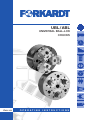
UBL / ABL
UNIVERSAL BALL-LOK
CHUCKS
E NGLISH
OPERATING
INSTRUCTIONS
BA-Nr.: UBL/ABL.E
CONTENTS
Edition: 01/2014
Contents
1.0
1.1
General information on documentation . . . . . . . . . . . . . . . . . . . . . . . . . . . . . . . . . .3
Explanation of the symbols . . . . . . . . . . . . . . . . . . . . . . . . . . . . . . . . . . . . . . . . . . . . . .3
2.0
2.1
2.2
2.3
2.4
2.5
2.6
General safety advice . . . . . . . . . . . . . . . . . . . . . . . . . . . . . . . . . . . . . . . . . . . . . . . . .4
General . . . . . . . . . . . . . . . . . . . . . . . . . . . . . . . . . . . . . . . . . . . . . . . . . . . . . . . . . . . . .4
Intended Use . . . . . . . . . . . . . . . . . . . . . . . . . . . . . . . . . . . . . . . . . . . . . . . . . . . . . . . . .4
Transport, handling and storage . . . . . . . . . . . . . . . . . . . . . . . . . . . . . . . . . . . . . . . . . .5
Operating information . . . . . . . . . . . . . . . . . . . . . . . . . . . . . . . . . . . . . . . . . . . . . . . . . .5
Maintenance and repair . . . . . . . . . . . . . . . . . . . . . . . . . . . . . . . . . . . . . . . . . . . . . . . . .5
Safety technology conditions for clamping devices . . . . . . . . . . . . . . . . . . . . . . . . . . .6
3.0
3.1
3.2
3.3
3.4
3.5
3.6
3.7
3.7.1
Set up and function . . . . . . . . . . . . . . . . . . . . . . . . . . . . . . . . . . . . . . . . . . . . . . . . . . .7
Description . . . . . . . . . . . . . . . . . . . . . . . . . . . . . . . . . . . . . . . . . . . . . . . . . . . . . . . . . .7
Jaws and grippers . . . . . . . . . . . . . . . . . . . . . . . . . . . . . . . . . . . . . . . . . . . . . . . . . . . . .7
Maintenance . . . . . . . . . . . . . . . . . . . . . . . . . . . . . . . . . . . . . . . . . . . . . . . . . . . . . . . . .7
Installation . . . . . . . . . . . . . . . . . . . . . . . . . . . . . . . . . . . . . . . . . . . . . . . . . . . . . . . . . . .8
Disassembly . . . . . . . . . . . . . . . . . . . . . . . . . . . . . . . . . . . . . . . . . . . . . . . . . . . . . . . . .9
Assembly . . . . . . . . . . . . . . . . . . . . . . . . . . . . . . . . . . . . . . . . . . . . . . . . . . . . . . . . . . . .9
Troubleshooting and grease information . . . . . . . . . . . . . . . . . . . . . . . . . . . . . . . . . .12
Recommended Chucking Ranges . . . . . . . . . . . . . . . . . . . . . . . . . . . . . . . . . . . . . . .13
4.0
4.1
4.2
4.3
4.4
4.5
4.6
4.7
Assembly . . . . . . . . . . . . . . . . . . . . . . . . . . . . . . . . . . . . . . . . . . . . . . . . . . . . . . . . . .14
Introduction . . . . . . . . . . . . . . . . . . . . . . . . . . . . . . . . . . . . . . . . . . . . . . . . . . . . . . . .14
Index . . . . . . . . . . . . . . . . . . . . . . . . . . . . . . . . . . . . . . . . . . . . . . . . . . . . . . . . . . . . . .14
Disassembled illustration - Each part's name . . . . . . . . . . . . . . . . . . . . . . . . . . . . . .15
Disassembling procedure of UBL chuck - ① ~ ⑩ . . . . . . . . . . . . . . . . . . . . . . . . . . .16
Component parts of jaw actuator - ① ~ ③ . . . . . . . . . . . . . . . . . . . . . . . . . . . . . . . .21
Checking of the condition of component parts - ① ~ ④ . . . . . . . . . . . . . . . . . . . . . .23
Re-assembling of UBL chuck - ① ~ ⑥
(Placing of housing / actuator / eccentric ball) . . . . . . . . . . . . . . . . . . . . . . . . . . . . .25
Re-assembling of UBL chuck - ① ~ ⑥ . . . . . . . . . . . . . . . . . . . . . . . . . . . . . . . . . . . . .
(Jaw actuator part) . . . . . . . . . . . . . . . . . . . . . . . . . . . . . . . . . . . . . . . . . . . . . . . . . . .28
Re-assembling of UBL chuck - ① ~ ⑤
(Placing jaw actuator into housing) . . . . . . . . . . . . . . . . . . . . . . . . . . . . . . . . . . . . . . .31
Re-assembling of UBL chuck - ① ~ ③ . . . . . . . . . . . . . . . . . . . . . . . . . . . . . . . . . . . . .
(Placing back plate) . . . . . . . . . . . . . . . . . . . . . . . . . . . . . . . . . . . . . . . . . . . . . . . . . . .34
4.8
4.9
4.10
2
5.0
5.1
5.2
Spare parts and service . . . . . . . . . . . . . . . . . . . . . . . . . . . . . . . . . . . . . . . . . . . . . .36
Spare parts . . . . . . . . . . . . . . . . . . . . . . . . . . . . . . . . . . . . . . . . . . . . . . . . . . . . . . . . .36
Customer service . . . . . . . . . . . . . . . . . . . . . . . . . . . . . . . . . . . . . . . . . . . . . . . . . . . .36
6.0
Declaration of incorporation . . . . . . . . . . . . . . . . . . . . . . . . . . . . . . . . . . . . . . . . . .37
BA-Nr.: UBL/ABL.E
Edition: 01/2014
GENERAL INFORMATION ON
DOCUMENTATION
1.0 General information on documentation
This user manual contains the essential information for the proper use of the clamping
device. It is addressed to technically qualified people.
Qualified people are:
• those who have received instruction on using the clamping device.
• those who have received training on setting up and repairing clamping devices,
and work as repair and servicing staff.
☞
For the operation, maintenance and repair of the clamping device it is
essential that the information in this manual is read and understood.
We reserve the right to make technical changes to the descriptions and statements in
this instruction manual that are essential to improve the clamping device.
The manual may not be copied, disseminated or used for competitive purposes in full
or in part.
The copyright for this manual belongs to FORKARDT DEUTSCHLAND GMBH.
1.1 Explanation of the symbols
Safety advice to prevent danger to life or reduce damage to property is shown in this
manual by the symbols and pictograms indicated here.
indicates potential risk. Death, severe physical injury or substantial damage to property may occur if the precautions are not undertaken or the
safety advice not adhered to.
☞
i
indicates important information on avoiding damage to property or undesirable operating states.
indicates information on handling or additional information.
3
BA-Nr.: UBL/ABL.E
GENERAL SAFETY ADVICE
Edition: 01/2014
2.0 General safety advice
2.1 General
Clamping devices may produce risks if the use and handling do not meet the requirements for safety technology. The clamping device is produced to the current state of
the technology and is safe to operate. Even so this clamping device may produce risks
if it is used improperly by unqualified people. The following information is to be used
for personal safety and to prevent damage to the product described or the connected
devices.
Read this manual before working with the clamping device and observe
all safety information. Not adhering to the instructions contained in this
manual may result in danger to life, severe personal injury or substantial
damage to property.
• Only qualified people may work with the clamping device.
• It is not permitted to change or alter the clamping device yourself.
• Only use the clamping device when it is in perfect condition.
• Before working on the clamping device, switch the machine off and ensure it can not
be switched on again.
• Only use original manufacturer components and spare parts. The warranty lapses if
parts from other manufacturers are used.
• Before starting to use the clamping device check whether all protective devices have
been attached.
• The "lathe – clamping device – work piece" system is primarily influenced by the
work piece being produced, which may result in a remaining risk. The operator must
assess the remaining risk.
The manufacturer is not liable for damage arising from not adhering to the manual.
2.2 Intended Use
The clamping device may only be used to clamp workpieces on machine tools. When
doing so the maximum axial force, clamping force and revolutions of the clamping
device may not be exceeded. The required clamping force must be determined for the
application in line with the applicable technical rules (e.g. VDI 3106). If in doubt or if
accessories are used that were not provided by the manufacturer, the manufacturer
must approve or restate the thresholds.
The following must be considered:
4
• Variable adhesion coefficients between work piece and top jaw
• Relationship between clamping diameter and working diameter
BA-Nr.: UBL/ABL.E
GENERAL SAFETY ADVICE
Edition: 01/2014
•
•
•
•
•
Size of cutting force on the cutting tool
Top jaws overhang from the clamping location
Reduction in clamping force via the centrifugal force for external clamping
The maximum revs stated only apply to hard standard top jaws
For special top jaws that are to be used for this chuck the maximum revs are
engraved on the jaws
Proper use includes adhering to the manufacturer's prescribed assembly, set-up, operation and maintenance terms. All other uses are considered to be unauthorised.
The manufacturer is not liable for damage thus caused.
2.3 Transport, handling and storage
Notify the forwarder if there is transport damage. Notify the manufacturer in writing
without delay if parts are missing. If the clamping device is not assembled immediately after delivery it must be stored in a protected location. Cover the parts properly and
protect from dust and moisture.
In order to protect all the blank parts, the clamping device and pressure oil cylinder,
and all accessories are covered with a protective substance on delivery.
2.4 Operating information
As per the regulations of the trade association, revolving clamping devices must be
secured from touching using appropriate covers or protective doors.
If faults occur on the clamping device during operation, the machine must
be switched off immediately and only restarted when the fault has been
resolved.
After switching off the clamping power the work piece may release itself from the
clamping device.
The local safety regulations and accident prevention rules of the appropriate trade
association apply to operating the clamping device.
2.5
Maintenance and repair
For maintenance and monitoring work ensure the clamping device is without
pressure.
At the high revs that are common on lathes, the clamping device is exposed to high
loads. It can be damaged during collisions between the tool and clamping device that
may occur occasionally, e.g. if the program process has faults damage may occur.
5
BA-Nr.: UBL/ABL.E
GENERAL SAFETY ADVICE
Edition: 01/2014
After a collision switch off the lathe immediately and check the clamping
device for damage. In addition to easily recognised damage, hidden
damage may also occur, e.g. hairline fractures in the chuck body or the
base jaws. Remove the clamping device immediately from the machine
spindle.
Analyse the affected parts of the clamping device with an appropriate, non-destructive testing procedure to ensure there are no fractures and exchange it if damage has
occurred.
☞
2.6
Only use original parts.
Safety technology conditions for clamping devices
The safety technology conditions for operating clamping devices under pressure are
defined in the trade association's testing guidelines and the DIN, VDE and VDI guidelines.
The individual test conditions are ensured via the following activities:
6
Test condition
Ensured via:
The machine spindle may only start when
the minimum clamping pressure in the
clamping cylinder has been built up.
Pressure switch in the clamping lines
The machine spindle may only start
if the jaw stroke clamping is in the
permitted range.
Clamping route monitoring on the
actuating cylinder
The clamping may only be released when
the machine spindle has stopped.
Standstill monitoring on the
machine spindle
If the clamping energy fails
the work piece remains clamped until
the spindle stops.
Unlockable non-return valve
in actuating cylinder
If the power fails and restarts the switching
detent positions do not change.
Impulse-controlled way valve with
end positions
If the clamping energy fails, a signal to
automatically or manually stop the spindle
is given.
At 1/5 of the maximum activation power the
clamping device used must open and close.
Pressure switch in the clamping line
BA-Nr.: UBL/ABL.E
SET UP AND FUNCTION
Edition: 01/2014
3.0
Set up and function
3.1
Description
The 3 jaw centralizing or compensating
chuck is a sealed unit, designed for
excellent performance, durability and
ease of maintenance. Its chucking action
is achieved by a ball joint mechanism.
Utilizing its radial and pull-back jaw stroke, draft angles of up to 5 degrees can be
safely gripped.
3.2
Jaws and grippers
Jaw safety screws (see chuck schematic)
retain the t-nuts in the ball arms. It is very
important that they are not removed and
remain fully tightened.
Special jaws can be designed to enhance the utilization of the chuck. Please consult
the Forkardt sales office for further information. Part prints and process sheets will be
required to complete the design.
The UBL is now available with post style arm quick change jaw solution. Please contact our sales office for more information.
3.3
Maintenance
At a minimum drawbar pull, check to ensure the chuck actuates smoothly. If this test
results in a rough or uneven actuation, apply the recommended grease, Chevron
Coupling Grease or equivalent, until the relief valve shows signs of excess grease. It is
recommended to establish a preventive maintenance schedule.
Visual inspection, operator care and periodic PM will enhance and extend the life of
the unit. Depending on the severity of this environment, it is recommended that the
chuck be disassembled and visually inspected for wear signs in the arms, bearings and
actua- tor every 6 months. If considerable wear is detected, replace the parts immediately.
Replacement arm kits and seal kits are available upon request. The Forkardt service
department offers repair services with original manufacturers warranty covering all
parts and labor.
7
BA-Nr.: UBL/ABL.E
SET UP AND FUNCTION
Edition: 01/2014
3.4
Installation
1.
Remove dust cap and top tooling as required to make mounting screw holes
accessible.
2.
Position machine drawbar in the fully retracted position.
3.
Support the chuck with a sling or eye bolt.
4.
Mount basic chuck assembly to machine spindle SECURELY. If a chuck adapter
is included, mount securely to your spindle first, then mount chuck to adapter.
5.
Insert the chuck mounting screws and tighten per the table 1 enclosed.
6.
Position machine drawbar in the full forward position. Fasten chuck actuator to
the machine drawbar
SECURELY with the drawbar bolt furnished.
Set machine drawbar operation pressure as specified on assembly drawing to
produce proper chucking pressure.
DO NOT EXCEED RECOMMENDED MAX PRESSURE SHOWN ON ASSEMBLY PRINT.
Check the installation and jaw stroke by opening and closing the chuck.
7.
Retighten the drawbar bolt and replace dust cap and top tooling.
8.
Make sure the unit is well lubricated using Chevron Coupling Grease or equivalent, and fully actuate the chuck a few times before use. For chucks with stiraround truing feature, follow above instructions while also adding these additional steps 9-12.
9.
After performing steps 1-3 above, remove the sub adapter from the chuck and
mount securely to the machine spindle.
10. Mount the chuck assembly to the sub adapter by HAND TIGHTENING the mounting screws. When tightening the draw bolt, only HAND TIGHTEN for now.
11. Set machine drawbar pressure at a low setting. Use the set screws spaced around
the OD of the chuck adapter to adjust the chuck to run true, while indicating the
central ID of the chuck body or a master part.
(Set up master furnished at extra cost).
Loosen the stir screw once the chuck is positioned. NEVER leave stir screws in
a high torque state.
12. Once chuck is running true, tighten the mounting screws per Table 1. Open the
chuck and tighten the drawbar bolt SECURELY.
Very carefully snug up the stir screws. DO NOT overtighten.
13. Follow instructions 7 & 8 above.
8
BA-Nr.: UBL/ABL.E
SET UP AND FUNCTION
Edition: 01/2014
3.5
3.6
Disassembly
1.
Remove all top tooling and clean the outside of the chuck. Set chuck on its face.
2.
Remove back adapter plate (spindle adapter should still be on machine).
3.
Remove exposed grease from inside of the chuck.
4.
Remove caps, at base of arms, and springs (if applicable).
5.
Place chuck on its side to remove the arms.
6.
To remove the arms, first remove the 4 SHCS from upper bearing and tap the bottom of the arm to remove it. Make sure to keep the bearings, homing pins, spring
and restrictor pin in sets. Repeat for each arm.
7.
Remove actuator from housing (remove actuator support from actuator, if applicable) by removing the tru-arc ring and spacer.
8.
Remove lower ball (eccentric ball) out of actuator. Removal is done by twisting the
ball to proper location and pulling outward.
9.
Clean all details for inspection.
Assembly
1.
Place the lower ball (eccentric ball) into the actuator, making sure balls move
freely.
2.
If compensating model, mount center actuator support and assemble with spacer and tru-arc ring.
3.
Install actuator into housing. Actuator on centralizing models has two positioning
lugs on 1 ear of actuator. This ear (with lugs) must be loaded into #1 bore (marked on top face of housing) of housing. On compensating models, the two positioning lugs are removed, but this ear must still be positioned into the #1 bore as
well.
4.
Once actuator is properly place into housing, turn over for assembly of arms and
upper bearing. Place key in lower shaft of arm.
5.
Place seal on arm, with Teflon cover facing the ball of the arm.
6.
Place restrictor pin, into restrictor spring, and then place both into center hole of
arm ball.
7.
Place homing pins into center hole of arm ball, with flat face to top arm platform.
8.
Vice clamps or equivalent will be required. Place the upper bearing around the
arm (making sure that the seal is seating within the seal groove). Using aforementioned clamps, squeeze the bearing together, ensuring that homing pins are
pushed in. Using a hose clamp (or similar), make sure that bearing is clamped
securely around arm.
9
BA-Nr.: UBL/ABL.E
SET UP AND FUNCTION
Edition: 01/2014
9.
Set the arm assembly into the arm cavity making sure the key in the arm and the
key-way in lower ball are in line. Remove hose clamp and slide arm assembly into
place and tap upper bearing down until arm and bearing are flush with top face
of housing. Secure this assembly in place with 4 mounting screws. Repeat with
remaining arms.
10. Place chuck on its face.
11. Fill the back side of chuck (with inner actuator exposed) with Chevron Coupling
Grease or equivalent. Replace cap and springs.
12. Place the adapter back onto chuck body.
Precaution must be taken to secure all items against the
effect of rotation.
10
BA-Nr.: UBL/ABL.E
SET UP AND FUNCTION
Edition: 01/2014
Service Kits
#1 Hardware Kit
#2 ECC Ball Kit
#3 Arm Kit
#4 Tee Nut Kit
#5 Upper Bearing Kit #6 Compensating Kit
(3) arm seal
(3) eccentric bearing
(1) front bearing
(3) t-nut
(3) front bearing
(1) retaining spacer
(3) arm key
(1) arm seal
(3) safety screw
(3) arm seal
(1) retaining ring
3) restrictor pin
(1) restrictor pin
(6) jaw screw
(3) homing spring
(1) homing spring
(3) spring cap
(1) spring cap
(3) arm key
(1) arm key
(1) pipe plug
(1) arm
(3) arm spring
(1) arm spring
(4) grease fittings
(2) homing pin
(6) homing pin
(1) centralizing pin
*When ordering service kits, please reference chuck type and size and kit number.
If your chuck requires repair beyond replacement of wear parts, please contact our
service department for assistance.
11
BA-Nr.: UBL/ABL.E
SET UP AND FUNCTION
Edition: 01/2014
METRIC SCREWS PROPERTY CLASS: 12.9
SCREW SIZE
M4 (.7)
M5 (.8)
M6 (1.0)
TORQUE N-m
4.6
9.5
16
M8 (1.25) M10 (1.5) M12 (1.75)
39
M14 (2.0)
M16 (2.0)
M18 (2.5)
M20 (2.5)
M22 (2.5)
135
215
330
455
650
870
5/8-11
3/4-10
7/8-9
1.0-8
43,500
3,400
6,000
8,400
12,500
77
INCH SCREWS PROPERTY CLASS: SAE J429 BLADE S
SCREW SIZE
TORQUE IN-LBS
1/4-20
5/16-18
3/8-16
200
425
300
7/16-14 1 1/2-13
1200
JAW FORCE AND RPM SPECS
CHUCK DIAMETER (IN)
6
8
10
12
15
18
MAX RPM
3,000
2,400
1,875
1,650
1,275
1,025
JAW FORCE PER JAW (LBS)
6,100
8,100
10,000
12,100
15,100
15,100
3.7
Troubleshooting and grease information
Grease your chuck at regular intervals. Grease will dissipate based on cycles. It is
recommended to grease the chuck daily. Indications of low grease, or lack of greasing
are run out and / or loss of grip force (possible part slippage).
12
•
Recommended grease for the UBL chuck is Chevron Coupling grease (factory
supplied).
•
Without a part in place, apply grease to each arm fitting (3 - 5 shots) along the
outside diameter, until grease is released from the pipe plug. The lower fitting
should get more grease as this is the one that will pop the pressure valve.
•
Actuate the chuck at full stroke approx. 5 to 10 times. This will further distribute
grease throughout the chuck.
•
Re-apply grease to the chuck until the grease is released.
•
Another source of part slippage is cylinder pressure. Ensure that cylinder
pressure is at the recommended level.
•
If part roundness is deteriorating, the jaw homing may not be functioning properly. To check this, use a wrench to “twist” the arm, without a part loaded. If the jaw
does not snap back into position. Loosen the screws that hold the top bearing in
place. Clamp the part and re-tighten the screws. Run a test part to ensure that
the issue has been resolved.
•
If you hear a noise, similar to a clunk, during actuation, this could be an indication your drawbar has become loose and is not secure.
BA-Nr.: UBL/ABL.E
SET UP AND FUNCTION
Edition: 01/2014
3.7.1 Recommended Chucking Ranges
„A“ Diameter
External Mode
„B“ Diameter
UBL size
Internal Mode
”A” Diameter
External Chucking Range
(Recommended)
”B” Diameter
Internal Chucking Range
(Recommended)
maximum / minimum
maximum / minimum
160
120 / 14
150 / 70
200
150 / 16
200 / 80
250
200 / 50
230 / 85
300
240 / 65
300 / 130
380
315 / 80
380 / 165
460
390 / 90
455 / 245
All sizes are in millimeters
13
BA-Nr.: UBL/ABL.E
ASSEMBLY
Edition: 01/2014
4.0
4.1
Assembly
Introduction
• Thank you very much for purchasing our UBL chuck.
• Our UBL chuck has different type components from general power chuck, contains
complex component parts such as sliding portion including spherical parts. A proper maintenance will allow high accuracy of a chuck for a long-term.
• This SERVICE MANUAL is as a means of supplementing of our INSTRUCTION
MANUAL illustrating with pictures. This must be used with our INSTRUCTION
MANUAL when assembling, exchanging component parts, or overhaul of a chuck.
Therefore please follow our INSTRUCTION MANUAL for final adjustment method
etc.
• In the procedures, please observe safety precautions etc. fully and do proper disassembling, assembling, and final inspection before using the chuck.
• In case the chuck does not move properly or normally at assembling and final
inspection, please contact us immediately.
• It is not guaranteed that the recovery of a chuck to initial condition by exchanging of
component parts and overhaul by using this SERVICE MANUAL.
4.2
Index
• Disassembled illustration - Each part's name
• Disassembling procedure of UBL chuck - ① ~ ⑩
• Component parts of jaw actuator - ① ~ ③
• Checking of the condition of component parts - ① ~ ④
• Re-assembling of UBL chuck
( Placing of housing / actuator / eccentric ball ) - ① ~ ⑥
• Re-assembling of UBL chuck
( Jaw actuator part ) - ① ~ ⑥
• Re-assembling of UBL chuck
( Placing jaw actuator into housing ) - ① ~ ⑤
• Re-assembling of UBL chuck
( Placing of back plate ) - ① ~ ③
14
BA-Nr.: UBL/ABL.E
ASSEMBLY
Edition: 01/2014
4.3 DISASSEMBLED ILLUSTRATION - EACH PART'S NAME
4.3.1 Centralizing type - 3 jaw
• When placing an order please indicate
which housing and actuator should be used,
as 2-jaw chuck with such housing and
actuator is different from in case of 3-jaw
chuck.
• [ ] means another name.
Your requests or orders without the name
in such [ ] are acceptable.
ATTENTION:
Pay special attention to problems that damage of T·nut and deformation of jaw
actuator will be happened, if understand dimention of jaw bolt is different from
one to another.
4.3.2 Compensating type - 3 jaw
• Only the parts of the Compensating type shown in this figure are different from those of the
Centralizing type. Also, a different type of pressure cap spring is employed by the
Compensating type. All the other parts are the same with the Centralizing type.
• As for the 2-jaw model, different types of housing and actuator are employed.
15
BA-Nr.: UBL/ABL.E
ASSEMBLY
Edition: 01/2014
4.4 DISASSEMBLING PROCEDURE OF UBL CHUCK - ① ~ ⑩
4.4.1 Disassembling procedure of UBL chuck - ①
Before disassembling
Disassembling procedure
of general UBL chuck
Remove all of the old top toolings (Jaw,
Stopper, Stopper ring etc.) before disassembling the chuck.
Left upper picture shows the front of
the chuck.
Left lower picture shows the back of
the chuck.
4.4.2 Disassembling procedure of UBL chuck - ②
How to remove back plate
After removing all of the old top tooling,
turn over the chuck body and remove
the 6 fixing bolts attaching the back
plate and the chuck body by L-wrench
and plastic hammer.
16
BA-Nr.: UBL/ABL.E
ASSEMBLY
Edition: 01/2014
4.4.3 Disassembling procedure of UBL chuck - ③
How to remove back plate
After removing all fixing bolts, remove
the adapter plate using jack bolts or
other kinds of bolts to jack bolt holes
(2 positions) (refer to left picture).
4.4.4 Disassembling procedure of UBL chuck - ④
Left picture shows the back plate is
removed from the chuck.
Clean all grease off inside of the chuck
by using the cup.
CAUTION:
If grease does not fill inside
of the housing, it would
cause seizure or broken of sliding portion of the actuator and the eccentric
ball. Make sure grease fills inside of the
chuck body securely.
After removing of grease, remove
• 1- the pressure cup,
• 2- the pressure cup spring
at the back side of the jaw
actuator from the chuck body.
17
BA-Nr.: UBL/ABL.E
ASSEMBLY
Edition: 01/2014
4.4.5 Disassembling procedure of UBL chuck - ⑤
How to remove jaw actuator part
Position the housing front side, remove
the fixing bolts (4 each) of the each
bearing race.
4.4.6 Disassembling procedure of UBL chuck - ⑥
How to remove jaw actuator part
After removing all the bearing race
fixing bolts ( 4pcs X 3 Jaws), remove
the jaw actuator + the bearing race part
from the front side of the chuck while
tapping the rear side of the chuck by a
plastic hammer.
18
BA-Nr.: UBL/ABL.E
ASSEMBLY
Edition: 01/2014
4.4.7 Disassembling procedure of UBL chuck - ⑦
How to remove jaw actuator part
After removing the jaw actuator part,
remove the actuator by tapping using a
fixing bolt etc. on the chuck central
portion of the housing surface.
4.4.8 Disassembling procedure of UBL chuck - ⑧
How to remove eccentric ball
The eccentric ball is built in the wing
portion of the actuator. Pay attention
since there is a little trick to it when
removing the eccentric ball.
First, push the OD of the eccentric ball
softly into inside (refer to left picture).
When pushing it to the half position
exactly (being turned right above), rotate it 180 degrees.
19
BA-Nr.: UBL/ABL.E
ASSEMBLY
Edition: 01/2014
4.4.9 Disassembling procedure of UBL chuck - ⑨
How to remove eccentric ball
The eccentric ball is built in the wing
portion of the actuator. Pay attention
since there is a little trick to it when
removing the eccentric ball.
First, push the OD of the eccentric ball
softly into inside (refer to left picture).
When pushing it to the half position
exactly (being turned right above), rotate it 180 degrees.
4.4.10 Disassembling procedure of UBL chuck - ⑩
How to remove eccentric ball
Left picture shows the eccentric ball is
removed from the actuator.
Remove all 3 eccentric balls from the
actuator.
20
BA-Nr.: UBL/ABL.E
ASSEMBLY
Edition: 01/2014
4.5 COMPONENT PARTS OF JAW ACTUATOR - ① ~ ③
4.5.1 Component parts of jaw actuator - ①
How to remove other small parts
around jaw actuator part
After removing the jaw actuator part
from the housing, remove all small
parts from the jaw actuator.
Remove the bearing race which is attached as holding around the jaw actuator.
4.5.2 Component parts of jaw actuator - ②
How to remove other small parts
around jaw actuator part
Remove all small parts inside of the jaw
actuator.
Component parts (each):
Element
Jaw actuator
1 pc.
Bearing race
1 set
(divided to 2 pcs)
Restrictor pin
2 pcs.
Restrictor rod
1 pc.
Restrictor spring
1 pc.
21
BA-Nr.: UBL/ABL.E
ASSEMBLY
Edition: 01/2014
4.5.3 Component parts of jaw actuator - ③
How to remove other small parts
around jaw actuator part
The bearing race is molded in one
piece and divided to 2 pcs as 1 set.
Attaching portion of each is slightly different and has some individual differences so make sure to keep them in sets
as left picture.
22
BA-Nr.: UBL/ABL.E
ASSEMBLY
Edition: 01/2014
4.6 CHECKING OF THE CONDITION OF COMPONENT PARTS - ① ~ ④
4.6.1 Checking of the condition of component parts - ①
Now disassembling has finished then
do inspection of each component
parts.
To use parts having run-out or seizurewould be a factor of broken or causing
severe damages to chuck's accuracy
and function.
If grease is not circulating in the inside
of spherical surface of the actuator and
outside of sliding part of the eccentric
ball, those portion will get seizure
(seems like plated) and it would make
the move of the jaw worse and affect
the chuck's accuracy.
4.6.2 Checking of the condition of component parts - ②
Also inspect the spherical portion of
the actuator and the bearing race. If
seizure is found on them, those surfaces would seem plated.
Check rust and sliding mark on them
too.
23
BA-Nr.: UBL/ABL.E
ASSEMBLY
Edition: 01/2014
4.6.3 Checking of the condition of component parts - ③
Example of defective parts
The surface of this jaw actuator of left
picture has rust. Need to change to
new one immediately.
Also the surface of this eccentric ball
has seizure.
4.6.4 Checking of the condition of component parts - ④
Example of defective parts
Left picture shows a broken bearing
race.
Definitely needs all broken parts to
change.
24
BA-Nr.: UBL/ABL.E
ASSEMBLY
Edition: 01/2014
4.7
RE-ASSEMBLING OF UBL CHUCK - ① ~ ⑥
PLACING OF HOUSING / ACTUATOR / ECCENTRIC BALL
4.7.1 Re-assembling of UBL chuck - ①
PLACING OF HOUSING / ACTUATOR / ECCENTRIC BALL
How to re-assemble
Check the number of parts as left picture if each of them does not have any
abnormality at the inspection of them
after the chuck is disassembled.
And change all defective parts which
has rust, worn-out, broken to new products.
First, assemble the actuator part.
Spread high-adhesive grease on inside
of the actuator. (We sell grease as a
product for repair.)
4.7.2 Re-assembling of UBL chuck - ②
PLACING OF HOUSING / ACTUATOR / ECCENTRIC BALL
How to re-assemble
Spread grease on the sliding portion of
the eccentric ball likewise.
After that, place the eccentric ball into
inside of the actuator. (Refer to disassembling procedure)
25
BA-Nr.: UBL/ABL.E
ASSEMBLY
Edition: 01/2014
4.7.3 Re-assembling of UBL chuck - ③
PLACING OF HOUSING / ACTUATOR / ECCENTRIC BALL
How to re-assemble
Left picture shows that the eccentric
ball is placed into the actuator. Make
sure that the eccentric ball is in a right
position. On OD clamping chuck, set
the key ditch outside. And on ID clamping chuck, set the key ditch inside.
After placing the eccentric ball into the
actuator, spread high-adhesive grease
on inside of the eccentric ball.
4.7.4 Re-assembling of UBL chuck - ④
PLACING OF HOUSING / ACTUATOR / ECCENTRIC BALL
How to re-assemble
Turn the housing over and place parts
of inside of the chuck.
Spread high-adhesive grease on the
actuator's sliding hole of the center of
the housing.
26
BA-Nr.: UBL/ABL.E
ASSEMBLY
Edition: 01/2014
4.7.5 Re-assembling of UBL chuck - ⑤
PLACING OF HOUSING / ACTUATOR / ECCENTRIC BALL
How to re-assemble
Now place the actuator into the housing.
Spread high-adhesive grease on the
sliding portion of wing part on 1 point
of outer of the actuator.
Spread high-adhesive grease on the
actuator shaft portion likewise.
4.7.6 Re-assembling of UBL chuck - ⑥
PLACING OF HOUSING / ACTUATOR / ECCENTRIC BALL
How to re-assemble
When placing of the actuator into the
housing of CENT chuck, pay attention
since the actuator can be placed into
only 1 position of where sliding portion
is bigger.
27
BA-Nr.: UBL/ABL.E
ASSEMBLY
Edition: 01/2014
4.8
RE-ASSEMBLING OF UBL CHUCK - ① ~ ⑥
JAW ACTUATOR PART
4.8.1 Re-assembling of UBL chuck - ①
JAW ACTUATOR PART
How to re-assemble
Next, place all of the parts of the jaw
actuator part.
First, place the bearing arm seal into
the jaw actuator.
Place the restrictor spring + restrictor
rod into the cavity of the center of the
actuator.
Spread small amount of grease referring to left picture.
4.8.2 Re-assembling of UBL chuck - ②
JAW ACTUATOR PART
How to re-assemble
Left picture shows all necessary parts
are placed into the jaw actuator.
If the chuck is 3 Jaw type, do the same
for 3 of the jaw actuator.
And then place the bearing race into
spherical portion of the jaw actuator
but before that, need to spread highadhesive grease on the sliding surface
of the spherical portion.
28
BA-Nr.: UBL/ABL.E
ASSEMBLY
Edition: 01/2014
4.8.3 Re-assembling of UBL chuck - ③
JAW ACTUATOR PART
How to re-assemble
ATTENTION:
The bearing race has a
ditch so that the arm seal
fits in. Place the arm seal into that ditch
securely.
Left picture shows that the arm seal
securely placed into the ditch of the
bearing race.
4.8.4 Re-assembling of UBL chuck - ④
JAW ACTUATOR PART
How to re-assemble
Next, set this assemble of the jaw actuator into the chuck by special installing
jig of left picture.
(We sell this special installing jig as an
optional extra.)
Put together the bearing race by a vice
as making sure that the restrictor pin
can fit into it well. (Refer to next page)
29
BA-Nr.: UBL/ABL.E
ASSEMBLY
Edition: 01/2014
4.8.5 Re-assembling of UBL chuck - ⑤
JAW ACTUATOR PART
How to re-assemble
Sandwich the bearing race portion by
your fingers as left picture, then fasten
them up by vice till the gap (connected
portion) of the bearing race fits perfectly.
If the arm seal sticks out or does not fit
in the bearing race, need to replace
them again in accordance with
“Re-assembling of UBL chuck - ③ Jaw
actuator part".
4.8.6 Re-assembling of UBL chuck - ⑥
JAW ACTUATOR PART
How to re-assemble
After placing the arm seal into the bearing race and fastening by the vice correctly, set the special installing jig referring to left picture.
After setting, fix it by fixing bolt and
remove from the vice.
30
BA-Nr.: UBL/ABL.E
ASSEMBLY
Edition: 01/2014
4.9
RE-ASSEMBLING OF UBL CHUCK - ① ~ ⑤
PLACING JAW ACTUATOR INTO HOUSING
4.9.1 Re-assembling of UBL chuck - ①
PLACING JAW ACTUATOR PART INTO HOUSING
How to re-assemble
After assembling the bearing race + the
jaw actuator, place them into the housing.
ATTENTION:
Before insert bearing race
set into housing, housing
round ditch must be seal to protect
enter water during using by water protection base material.
If not such sealing, water easy to enter
inside of chuck body then make
serious problem for the chuck even
change new parts.See left picture.
4.9.2 Re-assembling of UBL chuck - ②
PLACING JAW ACTUATOR PART INTO HOUSING
How to re-assemble
Before placing the jaw actuator into the
housing, spread high-adhesion grease
on the sliding portion of the ball.
Left picture shows the jaw actuator is
placed in.
CAUTION:
Place the key of the actuator into the key ditch of the
eccentric ball securely.
31
BA-Nr.: UBL/ABL.E
ASSEMBLY
Edition: 01/2014
4.9.3 Re-assembling of UBL chuck - ③
PLACING JAW ACTUATOR PART INTO HOUSING
How to re-assemble
After setting the jaw actuator into the
eccentric ball, loosen the bolts of the
installing jig and place the jaw actuator
setting portion into the housing by a
plastic hammer.
4.9.4 Re-assembling of UBL chuck - ④
PLACING JAW ACTUATOR PART INTO HOUSING
How to re-assemble
After placing the jaw actuator part, fix
each of them by the fixing bolts of the
bearing race.
Turn the housing over after fixing by all
of bolts.
32
BA-Nr.: UBL/ABL.E
ASSEMBLY
Edition: 01/2014
4.9.5 Re-assembling of UBL chuck - ⑤
PLACING JAW ACTUATOR PART INTO HOUSING
How to re-assemble
Set the pressure cup spring + cup into
the hole of the rear side of the jaw actuator.
After setting 3 places, fill the space
inside of the housing with Esso EP-1
High-pressure grade grease.
33
BA-Nr.: UBL/ABL.E
ASSEMBLY
Edition: 01/2014
4.10
RE-ASSEMBLING OF UBL CHUCK - ① ~ ③
PLACING BACK PLATE
4.10.1 Re-assembling of UBL chuck - ①
PLACING BACK PLATE
How to re-assemble
After filling with grease, place the back
plate on. Make sure that the fitting
marks surely fit.
Set all of fixing bolts, and fasten them
up evenly 1 by 1 in order.
4.10.2 Re-assembling of UBL chuck - ②
PLACING BACK PLATE
How to re-assemble
After fastening all of bolts evenly,
fasten again by a plastic hammer.
34
BA-Nr.: UBL/ABL.E
ASSEMBLY
Edition: 01/2014
4.10.3 Re-assembling of UBL chuck - ③
PLACING BACK PLATE
How to re-assemble
After fastening again, reassembling has
finished.
35
SPARE PARTS AND
SERVICE
5.0
Spare parts and service
5.1
Spare parts
☞
BA-Nr.: UBL/ABL.E
Edition: 01/2014
For reasons of safety and for the proper functioning only use original
FORKARDT parts. Refer to the component list for the item numbers.
Manufacturer's warranty only for FORKARDT original parts.
There is no product liability for damage incurred as a result of using third party parts
in our products.
5.2
Customer service
To order spare parts, please state the following information:
i
Name
Quantity
Ident. number
FORKARDT DEUTSCHLAND GMBH
Heinrich-Hertz-Straße 7
D-40684 Erkrath
36
Phone:
+49 211 2506 334
+49 211 2506 284
Fax:
+49 211 2506 236
Mr. Neuenfeldt
Mr. Herr Cordes
BA-Nr.: UBL/ABL.E
DECLARATION
OF INCORPORATION
Edition: 01/2014
6.0
Declaration of incorporation
The manufacturer
FORKARDT Deutschland GmbH
Heinrich-Hertz-Str. 7
D - 40699 Erkrath
herewith declares the following incomplete machines with the designations:
Type designation::
Universal Ball-Lok power chucks
Type:
UBL / ABL
• The general health and safety requirements according to Appendix I
of the aforementioned directive have been referred to and observed.
• The special technical documents according to Appendix VII B
have been prepared.
• The aforementioned special technical documents will be submitted
to the responsible authority as required.
• Commissioning is forbidden until it has been verified that the
machine in which the aforementioned machines are to be incorporated
comply with the specifications of the machinery directive.
Responsible for the documentation:
Oskar Weinert
Heinrich-Hertz-Str. 7
D - 40699 Erkrath
Date/Manufacturer's signature:
24.01.2014
Place: Erkrath
.............................................................
(Head of Design Mr Weinert)
Declaration of incorporation number:
UBL / ABL.E
As we are constantly engaged in improving our products, the dimensions and data given in this catalogue cannot always
correspond to latest design features and are subject to alteration without notice.
37
Speed meets
precision.
OUR BRANDS
O
C
A
T
I
O
N
S
FORKARDT DEUTSCHLAND GMBH
Heinrich-Hertz-Str. 7
D-40699 Erkrath
Phone: (+49) 211 25 06-0
Fax:
(+49) 211 25 06-221
E-Mail: [email protected]
FORKARDT FRANCE S.A.R.L.
28 Avenue de Bobigny
F-93135 Noisy le Sec Cédex
Phone: (+33) 1 4183 1240
Fax:
(+33) 1 4840 4759
E-Mail: [email protected]
FORKARDT USA
2155 Traversefield Drive
Traverse City, MI 49686, USA
Phone: (+1) 800 544-3823
(+1) 231 995-8300
Fax:
(+1) 231 995-8361
E-Mail: [email protected]
Website: www.forkardt.us
FORKARDT CHINA
Precision Machinery (Shanghai) Co Ltd
1F, #45 Building, No. 209 Taigu Road,
Waigaoqiao FTZ CHINA 200131,
CHINA
Phone: (+86) 21 5868 3677
E-Mail: [email protected]
Website: www.forkardt.us
© 2015 FORKARDT, Errors and omissions excepted.
W
O
R
L
D
W
I
D
E
FORKARDT INDIA LLP
Plot No. 39 D.No.5-5-35
Ayyanna Ind. Park
IE Prasanthnagar, Kukatpally
Hyderabad - 500 072
India
Tel:
(+91) 40 400 20571
Fax:
(+91) 40 400 20576
E-Mail: [email protected]
www.forkardt.com
www.forkardt.us
UBL ABL E 11/14 0.0 FK Edition 01/14
L
Printed in Germany
Innovative Technology by