1
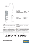
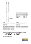
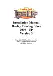
Kit Contents
11 Note!
Please note that there can be small differences
between your product and the images in
these instructions.
11 Note!
Please note that during storage and transport,
especially at high ambient temperature, some
of the oil and grease used for assembly may
leak and stain the packaging. This will not
cause damage to the product, wipe off the
excessive oil or grease with a cloth.
Description
Part No
Pcs
Cartridge kit
FKC101
1
Sticker top cap screw
00191-49
2
Sticker
01185-04
2
Owner’s manual
07288-01
1
Top out spring
21801-01
1
Oil lock sleeve
21802-01
1
11 Note!
Before you install this product, check the kit
contents. If anything is missing, please contact
an Öhlins dealer.
⚠⚠ Warning!
Before you install this product, read the Öhlins
Owner’s manual. This product is an important
part of the vehicle and the vehicle stability.
Cartridge kit for Harley-Davidson Touring FLHx/ FLTx 1997 - 2013
fkc 101
Mounting Instructions
mounting instructions
⚠⚠ Warning!
Before you begin
We strongly recommend to let an Öhlins dealer
install this product.
The kit consists of one compression cartridge
⚠⚠ Warning!
install each cartridge in the correct fork leg.
and one rebound cartridge. Make sure you
If you work with a lifted vehicle, make sure that it
is safely supported to prevent it from tipping over.
Compression cartridge
in the left side fork leg
11 Note!
Rebound cartridge
in the right side
fork leg
When you work with this product, see the
vehicle service manual for vehicle specific
procedures and important data.
11 Note!
Before you install this product clean the vehicle.
Tool
Part no
Pull-up tool
01765-08
Stopper plate
02810-03
Wrench
13 mm
Open end wrench
13/16’’
Open end torque wrench
13/16’’
Allen key
6 mm
Allen key torque wrench
6 mm
Remove the original damping system
1
YM 2002-2005 specific tools
Remove the front fork from the vehicle
according to the vehicle service manual.
Wrench 14 mm
Appropriate flat-head screwdriver to remove oil seal clip
Oil seal installation tool 41 mm
Oil seal grease according to vehicle service manual
2
mounting instructions
11 Note!
For MY 2002-2005 see the procedure on
pages 4-5.
3
2
⚠⚠ Warning!
Spring compression creates a potential danger
because of the violent force that loaded springs
are capable of. Important: When you remove the top cap push
down the top cap and at the same time pull up
the inner tube to prevent uncontrolled release.
2
Use a 13/16’’ open end wrench to loosen
and remove the top cap from the inner tube.
Important: When you remove the top cap push
down the top cap and at the same time pull up
the inner tube to prevent uncontrolled release.
3
A
B
Remove the main spring.
11 Note!
When you work with the fork leg, make sure
that the inner tube (A) is at lowest position to
keep the oil lock sleeve (B) correctly positioned
inside the inner tube.
4
Drain the fork leg from oil.
5
Use a 6 mm Allen key to remove the bottom
6
screw. Make sure not to lose the washer.
6
Remove the damping rod from the fork leg.
Do not remove the top out spring. If the top
out spring falls out with the damping rod, put it
back in the fork leg.
Lowering kit 08865-01 only:
Install the spacer (21803-01) (A) and the top
out spring (B) in the fork leg.
✋✋ Caution!
Make sure to install
the spacer and
the spring in the
correct order.
Lowering kit
08865-01:
B
A
5
3
mounting instructions
Remove the damping system MY 2002-2005
2
⚠⚠ Warning!
3
4
Spring compression creates a potential danger
because of the violent force that loaded springs
are capable of. Important: When you remove the top cap push
down the top cap and at the same time pull up
the inner tube to prevent uncontrolled release.
2
Use a 13/16’’ open end wrench to loosen the
top cap from the inner tube.
Important: When you remove the top cap push
down the top cap and at the same time pull up
the inner tube to prevent uncontrolled release.
3
Use a 14 mm wrench and a 13/16’’ open end
wrench to loosen and remove the top cap from
Remove the damping system MY 2002-2005
the shaft.
4
Remove the main spring.
5
Drain the fork leg from oil.
7
6
Use a 6 mm Allen key to remove the bottom
screw. Make sure not to lose the washer.
7
Remove the cartridge from the fork leg.
6
4
mounting instructions
8
Use appropriate tool to carefully remove the oil
8
seal clip.
9
Remove the inner tube from the outer tube,
refer to the vehicle service manual.
10
Examine the oil seal, bushings and oil seal clip
for wear. Replace if needed.
11
Apply oil seal grease according to the vehicle
9
service manual on the oil seal surfaces inside
the outer tube, and, on the outside of the oil
seal.
12
Put the oil lock sleeve (21802-01) in the outer
12
Remove the damping system MY 2002-2005
tube. Make sure to install it correctly.
13
Install the inner tube in the outer tube. Make
sure that the inner tube is completely inserted
in the outer tube. Make sure that the oil lock
sleeve is installed correctly.
14
Install the oil seal and bushing according to the
14
vehicle manual.
15
Install the oil seal clip.
13
16
Install the top out spring (21801-01) in the fork leg.
Lowering kit 08865-01 only:
Install the spacer (21803-01) (A) and the top
out spring (B) in the fork leg.
16
✋✋ Caution!
Make sure to install
the spacer and
the spring in the
correct order.
Lowering kit
08865-01:
B
A
5
mounting instructions
Install the Öhlins cartridge kit (all models)
2
1
1
Remove the screw top cap, top cap and the
guide sleeve external from the shaft.
2
Adjust the shaft nut as far up as possible on
the shaft, leave enough threads on the shaft to
install the pull up tool.
3
Install the pull up tool (01765-08) on the shaft.
Tighten with your hand.
✋✋ Caution!
Keep the fork leg in a vertical position during
the installation procedure.
4
3
Make sure that the oil lock sleeve is in correct
5
position.
✋✋ Caution!
Make sure that the guide sleeve internal
touches the seal head. Make sure that the guide sleeve internal is
correctly positioned during the installation
procedure, steps 5-11.
5
Put the cartridge in the fork leg.
6
Make sure that the cartridge is in bottom
4
position. Apply threadlocker (see the vehicle
service manual) on the bottom screw. Insert
the washer and the bottom screw. Use a 6 mm
Allen key to tighten the bottom screw. Tighten
according to the vehicle service manual.
7
Pour approximately 300 ml Öhlins front fork
fluid (01309-XX) in the fork leg.
If the oil level comes near the upper end of the
inner tube, move the steel tube up and down to
let out all air from the fork leg.
6
8
Pull the inner tube up and down approximately
10 times to aerate the fork leg.
6
mounting instructions
9
Pull the shaft up and down approximately 10
10
times to aerate the cartridge.
X
10
Make sure that the shaft assembly is in the
bottom of the fork leg and that the outer tube
is in bottom position. Measure the oil level with
a ruler. For recommended oil level, see setup
data in this folder.
11
Make sure that the guide sleeve internal is
correctly positioned. Make sure that the mark
11
on the main spring is up. Install the main spring
12
over the pull up tool (01765-08).
12
Carefully install the guide sleeve external.
✋✋ Caution!
The guide sleeve external is easily damaged.
13
Push the spring and the guide sleeve external
down, and at the same time pull up the
shaft.Carefully insert the stopper plate tool
(02810‑03) below the shaft nut.
14
Remove the pull up tool from the shaft.
15
13
Make sure that the stopper plate tool stays in
place. Use a 13 mm wrench to adjust the shaft
14
nut until bottomed.
16
Install the top cap on the shaft until stop.
11 Note!
16
Make sure that the top cap is completely
bottomed.
17
Use a 13/16 open end torque wrench and
a 13 mm wrench to tighten the shaft nut to the
top cap. Tighten the shaft nut to 15 Nm.
7
15
18
Push down the guide sleeve external and
carefully remove the stopper plate tool. Make
19
sure not to damage the guide sleeve external.
19
Pull up the inner tube and at the same time
push down the top cap. Use a 13/16” open
end torque wrench to tighten the top cap to
the inner tube. Tighten the top cap, refer to the
vehicle service manual.
20
Install the fork legs in the vehicle, refer to the
vehicle manual.
⚠⚠ Warning!
Make sure to install all removed parts in
the same positions as they were before the
installation of the öhlins cartridge kit.
11 Note!
After you have installed the cartridge in the fork
leg, place the sticker (01185-04) on the top cap.
Setup data
Spring guide
Öhlins Front fork fluid
01309-xx
Recommended oil level
80
mm
Make sure you choose the correct spring for
your rider weight, driving style and preferences.
Contact an authorized Öhlins service center
for advice.
Ride height
Spring
part no
Spring rate
N/mm
One driver, no extra load
Recommended spring
08419-10
10
Lowering kit 25 mm*
08865-01
13
* For best handling characteristics, we recommend to combine
this kit with a lowered rear (12 mm). To lower the rear, contact an
authorized Öhlins service center.
Öhlins products are subject to
continuous improvement and
development, therefore, although
these instructions include the most
up-to-date information available at
the time of printing, minor updates
may occur.
© Öhlins Racing AB. All rights
reserved. Any reprinting or
unauthorized use without the written
permission of Öhlins Racing AB
is prohibited.
To find the latest information
contact an Öhlins distributor.
Please contact Öhlins if you have
any questions regarding the
contents in this document.
Öhlins Racing AB
Box 722
S-194 27 Upplands Väsby, Sweden
Phone +46 8 590 025 00
fax +46 8 590 025 80
Part no. MI_FKC101_0
Issued 2014-04-16