1
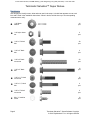
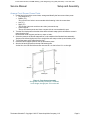
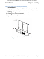
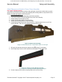
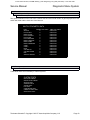
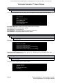
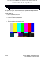
To Purchase This Item, Visit BMI Gaming | www.bmigaming.com | (800) 746-2255 | +1.561.391.7200 Super Deluxe Setup and Operation Service Manual Software Version 1.20.00 Terminator Salvation™ Copyright © 2010 T Asset Acquisition Company, LLC Terminator Salvation™ Game Software Copyright © 2010 PlayMechanix™ Inc. All rights reserved. This software is based in part on the work of the Independent JPEG Group. This product includes software developed by the OpenSSL Project for use in the OpenSSL Toolkit. (http://www.openssl.org/) This product includes cryptographic software written by Eric Young ([email protected]) To Purchase This Item, Visit BMI Gaming | www.bmigaming.com | (800) 746-2255 | +1.561.391.7200 Terminator Salvation™ Super Deluxe Table of Contents Safety........................................................................................................................................................... 3 Product Specifications................................................................................................................................. 5 Hardware..................................................................................................................................................... 6 Setup and Assembly.................................................................................................................................... 8 Diagnostic Menu System........................................................................................................................... 24 Maintenance.............................................................................................................................................. 40 Wiring......................................................................................................................................................... 43 Parts.......................................................................................................................................................... 49 Troubleshooting......................................................................................................................................... 53 Contact Information.................................................................................................................................... 56 Page 2 Terminator Salvation™ Game Software Copyright © 2010 PlayMechanix™ Inc. All rights reserved. To Purchase This Item, Visit BMI Gaming | www.bmigaming.com | (800) 746-2255 | +1.561.391.7200 Service Manual Safety Safety OPERATION Before operating game, read this manual. Failure to properly install and operate this game could result in malfunction or accident. Operate the game in accordance with the manual. TRANSPORTING The cabinet is very heavy. Because the monitor is high, the cabinet is also very top-heavy. Use appropriate care when moving or transporting cabinet. It contains fragile glass and electronic components. Avoid rough handling. PROXIMITY TO NEON LIGHTS Locating the cabinet near neon lights may reduce the ability of the IR sensors to accurately track the guns. It is recommended that the cabinet be placed far away from neon lights or that any nearby neon lights be turned off. HANDLING COMPONENTS Many components are extremely sensitive to handling, environmental and Electrostatic Discharge (ESD) events, especially the computer. Do not handle it roughly. Before servicing, call your distributor and inquire about the PC warranty. Use proper ESD procedures when servicing. Protect components from harmful environmental conditions, such as extreme temperatures, excessive moisture or other damaging effects. DISCONNECT POWER Always turn the power off and unplug the unit before servicing or making adjustments unless otherwise instructed. Installing or repairing components while power is on can damage the components and void the warranty. GROUNDING Avoid electrical shock. Do not plug in AC power until you have inspected and properly grounded the unit. Only plug into a grounded, three-wire outlet. Do not use a “cheater” plug or cut off the ground pin on the line cord. ELECTRICAL SHOCKS There is no isolation transformer in the cabinet. Disconnect AC power before servicing. However, be aware that lethal voltages can remain in the electronic components even when AC power is disconnected. Use extreme caution when servicing. Verify that there is a working ground connection. If the unit sustains water damage, cease using it immediately and unplug AC power. MONITOR Extremely high voltages exist in the video monitor at all times. These high voltages exist even when the monitor is off and the AC line cord is disconnected. These voltages are extremely lethal and will cause death. The monitor contains no user serviceable parts. Do not attempt to service the monitor. POWER SELECTOR Before installing game, ensure the voltage on the PC is set properly. There is a 115/230 VAC selector switch that must be set for the correct voltage for your site. Verify the fluorescent lamp rating. The rating must match the line voltage at the installation site. POWER CORD If the power cord is damaged or lost, replace it with an identical cord as supplied by the manufacturer or an authorized service agent. Terminator Salvation™ Copyright © 2010 T Asset Acquisition Company, LLC Page 3 To Purchase This Item, Visit BMI Gaming | www.bmigaming.com | (800) 746-2255 | +1.561.391.7200 Terminator Salvation™ Super Deluxe CONNECTORS Ensure all connectors mate properly. If connectors do not slip in easily, do not force them. Connectors are often keyed and only connect one way. Check for correct orientation. COMPUTER The computer contains sensitive components, including a hard drive. Do not handle it roughly. Call your distributor before servicing its internal components. Ask about warranty information as it relates to the PC. Do not turn the PC power switch on or off. It should remain permanently in the ON position. Cycle AC power on or off with the cabinet power switch. A dongle has been inserted into one of the USB ports. This is required for game play. Do not remove the dongle except for troubleshooting purposes. FLUORESCENT TUBES A dropped fluorescent tube may break and implode. Shattered glass from the implosion can travel long distances and cause bodily injury. Use proper procedures when handling broken materials, as these items can contain hazardous material such as mercury or lead. WATER JETS Do not install or operate game within operating perimeter of a water jet. Do not clean equipment using water jet. HAZARD TO EPILEPTICS A small portion of the population has an epileptic condition that may cause seizures. Affected persons experience seizure while watching some television pictures or playing certain video games. People who have not had seizures may still have an undetected epileptic condition. If anyone in your family has experienced epilepsy symptoms (seizures or loss of awareness), consult your physical before using video games. While children play video games, a parent should observe. Be alert to the following symptoms: dizziness, altered vision, eye or muscle twitching, involuntary movements, loss of awareness, disorientation or convulsions. If you or your child experiences these symptoms, discontinue use immediately and consult your physician. MANUAL Keep this manual available and ready for use. If the game fails to function properly, turn off the machine and unplug the AC line cord. Contact your local distributor. Your warranty, when applicable, lasts 60 days from your purchase date. You may not reproduce this document or any of its contents without written authorization from Raw Thrills, Inc. or Play Mechanix™ Inc. SPECIFICATIONS For reasons such as performance, this product’s specifications may change without notice. Federal patent, copyright and other intellectual property laws protect the content, devices and design of the game and its equipment. Page 4 Terminator Salvation™ Game Software Copyright © 2010 PlayMechanix™ Inc. All rights reserved. To Purchase This Item, Visit BMI Gaming | www.bmigaming.com | (800) 746-2255 | +1.561.391.7200 Service Manual Product Specifications Product Specifications Electrical Power Domestic, international users and Japan 120 VAC @60 Hz, 5 amps 240 VAC @ 50 Hz, 2.5 amps 100 VAC @ 50 Hz, 5 amps DC Power Fuse Guide +5 VDC +12 VDC 2 amp Slow Blow 7 amp Slow Blow Temperature 32 degrees F to 100 degrees F (0 degrees C to 38 degrees C) Humidity Must not exceed 95% relative humidity Dimensions Screen assembly: height: 121” when fully assembled width: 97.5” depth: 18.5” Screen marquee: height: 16” Gun pedestal/outriggers: height: 37.25” width: 76” depth: 31” Carton Specs 37" x 50" x 85" tall - 456 lbs 26" x 98" x 27" tall - 305 lbs 33" x 47" x 46.5" tall - 257 lbs Terminator Salvation™ Copyright © 2010 T Asset Acquisition Company, LLC Page 5 To Purchase This Item, Visit BMI Gaming | www.bmigaming.com | (800) 746-2255 | +1.561.391.7200 Terminator Salvation™ Super Deluxe Hardware Use this page to identify screws, bolts and nuts used in the setup. A circled letter appears next to each item and is used in the installation instructions. When in doubt, hold the item up to its corresponding measurement to verify. ¼-20 black washer 24 pcs. ¼-20 nylon insert nut 4 pcs. ¼-20 x ¾" black bolt 38 pcs. ¼-20 x 2" black bolt 4 pcs. ¼-20 x 2” black torx screw 20 pcs. ¼-20 x 3" black bolt ¼-20 x 1 ¼" black torx screw 12 pcs. ¼-20 x 1 ½” black bolt 4 pcs. ¼-20 x ¾” black torx screw 4 pcs. #8 x ½” machine screw 10 pcs. Page 6 10 pcs. Terminator Salvation™ Game Software Copyright © 2010 PlayMechanix™ Inc. All rights reserved. To Purchase This Item, Visit BMI Gaming | www.bmigaming.com | (800) 746-2255 | +1.561.391.7200 Service Manual Terminator Salvation™ Copyright © 2010 T Asset Acquisition Company, LLC Page 7 To Purchase This Item, Visit BMI Gaming | www.bmigaming.com | (800) 746-2255 | +1.561.391.7200 Terminator Salvation™ Super Deluxe Setup and Assembly Unpack Carton 1. 2. 3. 4. 5. 6. 7. Move shipping carton near assembly site. Remove banding straps and open carton. Remove boxes from the top of the carton. Remove corrugated sides and corners from container. Unpack remaining boxes. Set hardware bag aside. Remove all contents from boxes and inspect. For this assembly, you will need • One or two assistants, • • Two six-foot ladders, • • Phillips head screwdriver, • • 3/8 socket wrench, 7/16 socket wrench, T-25 security torx screwdriver (included in kit) Level Assemble Screen Base USES HARDWARE KIT A 1. Identify a site for the game that: • Has a grounded AC outlet • Has about 10 horizontal feet of unobstructed wall space with no windows, Light may shine through behind the screen or cast shadows • Has about 20 feet of open space from the wall • Has at least nine feet ceiling clearance, in order to raise the front screen frame assembly cleanly over the screen base • Is moderately dark • Is away from neon lights (which impair the IR sensors) • Has a relatively flat floor 2. Position the screen base halves about 3 feet from the wall so that the 12 infrared (IR) sensors face away from the wall. 3. Remove the screws holding the access doors on the left and right screen base halves. 4. Remove the access doors and set aside. 5. 6. 7. 8. Page 8 Figure 1: Screen Base Assembly Using four bolts, fasten the left and right screen base halves together. Connect the IR LED Board power cables Place a level on top of the screen base. Adjust the six leg levelers beneath the screen base until it is level front to back as well as left to right. Turn the knobs at the base of the levelers to raise and lower the screen base. Terminator Salvation™ Game Software Copyright © 2010 PlayMechanix™ Inc. All rights reserved. To Purchase This Item, Visit BMI Gaming | www.bmigaming.com | (800) 746-2255 | +1.561.391.7200 Service Manual Setup and Assembly Arrange Front Screen Frame Posts 1. On the floor in front of the screen base, arrange and identify the front screen frame posts: • Top (stamped “A”), • Bottom (“B”), This post has four holes to accommodate bolts fastening it into the screen base. • Left (“C”), • Right (“D”) The left and right posts each have two holes just near the top. • Center support The top and bottom posts each have a square hole to accommodate this post. 2. Turn the four black posts so that the sides with the female snaps (which will hold the screen in place) face the floor. Note that the center support post has no snaps or holes. 3. Orient the posts so the female snaps will be on the outside of the finished frame assembly. Snaps on the left and right posts form a straight line with snaps on the top and bottom posts. 4. Turn all the posts so the snaps face the floor. 5. Insert the center support post into the top and bottom posts. 6. Abut the left and right posts to the top and bottom posts. On the floor, the right and left posts are reversed. D is on the left and C is on the right. Figure 2: Front Screen Assembly During final assembly orientation is reversed. In this image, the right post “D”is on the left. Terminator Salvation™ Copyright © 2010 T Asset Acquisition Company, LLC Page 9 To Purchase This Item, Visit BMI Gaming | www.bmigaming.com | (800) 746-2255 | +1.561.391.7200 Terminator Salvation™ Super Deluxe Assemble Front Screen Frame USES HARDWARE KIT B 1. Align holes of “A” corner bracket with holes in top and right posts. The perpendicular wing should point up. See Figure 2A. 2. Insert four bolts through “A” corner bracket into posts. Do not tighten. 3. Repeat steps 1-2 for corner “B” bracket and top and left posts. 4. 5. 6. 7. 8. 9. 10. Figure 2a: Front Screen Assembly – Corner Bracket Close-up of right and top posts and “A” corner bracket. Align holes in brackets with holes in posts and fasten bolts. Note orientation of perpendicular flap on the right of the assembly. Align T bracket with right and bottom posts. Insert five bolts through T bracket. Do not tighten. Repeat steps 4-5 with left and bottom posts. Tighten all bolts. Align hole in a cross joiner with hole in perpendicular flap of an “A” corner bracket. Affix one bolt through the corner bracket flap into the cross joiner. Tighten bolt. See Figure 3. Repeat steps 8-9 with remaining cross joiner into a “B” corner bracket. Page 10 Terminator Salvation™ Game Software Copyright © 2010 PlayMechanix™ Inc. All rights reserved. To Purchase This Item, Visit BMI Gaming | www.bmigaming.com | (800) 746-2255 | +1.561.391.7200 Service Manual Setup and Assembly Attach Front Screen Frame Assembly to Screen base USES HARDWARE KIT B 1. With an assistant, carefully insert the left and right posts of the front screen frame assembly into holes on top of screen base. Snaps face away from the wall; cross joiners point to the wall. See Figure 3. 2. Lift the left post slightly to align the top holes on the side of the screen base with the top hole in the left post. 3. Affix one bolt with washers through screen base into the left post. 4. Repeat steps 2-3 for right post. Do not tighten bolts. 5. Insert four bolts with through holes of bottom post into screen base. 6. Tighten all bolts. Figure 3: Screen Base Assembly with Front Screen Assembly Image is oriented from the rear with an access panel removed. Terminator Salvation™ Copyright © 2010 T Asset Acquisition Company, LLC Page 11 To Purchase This Item, Visit BMI Gaming | www.bmigaming.com | (800) 746-2255 | +1.561.391.7200 Terminator Salvation™ Super Deluxe Assemble Rear Screen Frame USES HARDWARE KIT B 1. Identify the three rear screen frame posts: • The top post, marked “G,” has four evenly spaced holes. • The left (“E”) and right (“F”) posts have two holes at the top and one near the bottom. 2. Lay out three posts of rear screen frame on the ground according to Figure 4. When laid out properly, the bolt holes on the left and right posts face outward. 3. Align holes of remaining “A” corner bracket with holes of top and left posts. See Figure 2A. 4. Insert four bolts through the “A” bracket into posts. Do not tighten. 5. Repeat steps 3-4 for the remaining “B” corner bracket and top and right posts. 6. Tighten all bolts. Figure 4: Rear Screen Frame Assembly Page 12 Terminator Salvation™ Game Software Copyright © 2010 PlayMechanix™ Inc. All rights reserved. To Purchase This Item, Visit BMI Gaming | www.bmigaming.com | (800) 746-2255 | +1.561.391.7200 Service Manual Setup and Assembly Attach Rear Screen Frame Assembly to Screen Base USES HARDWARE KIT B 1. Align holes at bottom of rear screen frame assembly posts with holes in rear of screen base. The perpendicular flaps on the rear screen frame assembly should be very near the cross joiners. See Figure 5. 2. Affix two bolts through each post into the screen base. Do not tighten bolts. 3. Align hole on left cross joiner with hole on “A” corner bracket on rear screen frame. 4. Insert bolt through flap into cross joiner. Do not tighten. 5. Repeat steps 3-4 through “B” corner bracket. 6. Tighten all bolts. Figure 5: Screen Base Assembly with Rear Screen Assembly Image is oriented from the rear with an access panel removed. Attach Lower Screen Spacer to Frame Assembly USES HARDWARE KIT C 1. Lift the lower screen spacer panel sub-assembly into place. Z-brackets should rest on bottom of front screen assembly. 2. Tighten down z-brackets on spacer panel. 3. Position lower right snap bracket on top of spacer panel. 4. Affix five screws through snap bracket into spacer panel. Do not tighten. 5. Insure snaps form a straight line and tighten all bolts and screws. Figure 6: Lower Screen Spacer Image is oriented from the rear. Snap bracket shown is on the left. Terminator Salvation™ Copyright © 2010 T Asset Acquisition Company, LLC Page 13 To Purchase This Item, Visit BMI Gaming | www.bmigaming.com | (800) 746-2255 | +1.561.391.7200 Terminator Salvation™ Super Deluxe Assemble Screen Frame Panels USES HARDWARE KIT C 1. Align holes of left side panel with holes on left of screen frame assembly. 2. Affix six screws with washers through left side panel into screen frame assembly. Tighten screws. 3. Repeat steps 1-2 for right side panel. Figure 7: Screen Panel Assembly Page 14 Terminator Salvation™ Game Software Copyright © 2010 PlayMechanix™ Inc. All rights reserved. To Purchase This Item, Visit BMI Gaming | www.bmigaming.com | (800) 746-2255 | +1.561.391.7200 Service Manual Setup and Assembly Attach Marquee and Heads to Screen Frame Assembly Use Caution Climbing Ladders The marquee assembly and heads are heavy, bulky and fragile. Use extreme caution when you and a partner lift them to the top of the screen frame assembly while climbing ladders or step stools. Ensure ladders are stable and located on solid, flat ground. USES HARDWARE KIT C 1. Lift terminator head sub-assembly atop screen frame assembly. 2. Lift second terminator head sub-assembly atop screen frame assembly. 3. Position heads to left and right of center. 4. Locate 5V head power cable in left screen base. 5. Thread cable up through base to connect to heads. 6. Lift marquee assembly atop screen frame assembly. Z-brackets should rest on top of front screen assembly. Take care not to snag the connected power cable. Figure 8: Marquee Sub-Assembly Image is oriented from the rear. Snap bracket shown is on the right. 7. Affix upper left snap bracket using to marquee using screws. Do not tighten. 8. Insure snaps align correctly to form straight lines and tighten all bolts and screws. Figure 8a: Upper Left Snap Bracket Assembly Insure snaps form a straight line before tightening into place. 9. Connect marquee power cable to matching cable from left screen base. Terminator Salvation™ Copyright © 2010 T Asset Acquisition Company, LLC Page 15 To Purchase This Item, Visit BMI Gaming | www.bmigaming.com | (800) 746-2255 | +1.561.391.7200 Terminator Salvation™ Super Deluxe Affix Screen to Screen Frame Assembly 1. Unroll screen so that male snaps face the wall and the label is in the bottom left corner. 2. Starting at top corners, snap screen onto front of screen frame assembly. Use ladders as needed. Screen material stretches to fit frame. Attach Floor Supports to Screen base USES HARDWARE KIT D 1. Position floor support sections along side the screen base. Figure 9: Floor Support Assembly 2. Thread cables from the screen base into the short bent segment of the floor support. Left side will have two cables while right side will have only one. 3. Align holes on floor support flange with holes on side of screen base. 4. Insert two bolts with washers through flange into screen base. Do not tighten bolts. 5. Thread cables from short bent segment through long straight segment of floor support. Figure 9a: Routing Floor Support Cables 6. Connect the long segment onto the metal connector sleeve. 7. Affix segments together by inserting four bolts through long straight segment into connector sleeve. Take care to avoid the cables within the floor support. Do not tighten bolts. 8. Repeat steps 1-7 for right floor support. 9. Replace both screen base access doors. 10. Replace screws to secure access doors. Page 16 Terminator Salvation™ Game Software Copyright © 2010 PlayMechanix™ Inc. All rights reserved. To Purchase This Item, Visit BMI Gaming | www.bmigaming.com | (800) 746-2255 | +1.561.391.7200 Service Manual Setup and Assembly Open Gun Pedestal Coin Door 1. Remove the coin door key from the coin return chute. 2. Open gun pedestal coin door. Note the position of the Service Button Panel. 3. Locate the keys for the projector access door and lower access door on the inside of the coin door. Remove the projector remote control from the cash box. Connect Floor Support Cables to Gun Pedestal 1. 2. 3. 4. 5. Position gun pedestal near floor supports. Remove gun pedestal lower door. Connect the 2-pin 5V IR cables from the left floor support to its mate inside the gun pedestal. Connect the 2-pin AC plug from the left floor support to its mate inside the gun pedestal. Connect power cable from right floor support to gun pedestal power outlet. Attach Outrigger Braces to Outriggers USES HARDWARE KIT ATTACHED TO OUTRIGGER 1. Position outrigger to near gun pedestal. torx screws. Connect upper outrigger brace to outrigger using four torx screws. 2. Connect lower outrigger brace to outrigger using two Do not tighten. 3. Do not tigthen. Be sure to match the angle of lower brace. 4. Verify outrigger braces line up correctly to gun pedestal. 5. Tighten down screws. 6. Repeat steps 1-5 for second outrigger. Connect Outrigger Cables 1. Remove six screws from rear door of outrigger. 2. Remove outrigger rear door and set aside. 3. Locate outrigger power cables inside gun pedestal. There are 5 connectors needed for each outrigger. 4. Thread cables from gun pedestal through upper outrigger brace into outrigger. 5. Connect the three 2-pin connectors and two three pin-connectors. 6. Repeat steps 1-5 for second outrigger. Terminator Salvation™ Copyright © 2010 T Asset Acquisition Company, LLC Page 17 To Purchase This Item, Visit BMI Gaming | www.bmigaming.com | (800) 746-2255 | +1.561.391.7200 Terminator Salvation™ Super Deluxe Attach Outriggers to Gun Pedestal USES HARDWARE KIT ATTACHED TO OUTRIGGER 1. Align outrigger brace with gun pedestal. screws. Connect upper outrigger brace to gun pedestal using four torx screws. 2. Connect lower outrigger brace to gun pedestal using two 3. 4. 5. 6. 7. Replace outrigger door. Fasten six screws to hold door to outrigger. Repeat steps 1-5 for second outrigger. Tighten all screws. Figure 10: Gun Pedestal with Outriggers Attach Floor Supports to Gun Pedestal USES HARDWARE KIT D 1. Move gun pedestal to floor supports flanges. 2. Position gun pedestal so that posts on gun pedestal mounting plate protrude through holes on floor supports flanges. 3. Fasten a nut and a washer over each post. Do not tighten nuts. 4. Adjust gun pedestal leg levelers to raise the wheels just above the floor to keep the pedestal stable. Leveling does not need to be perfect yet. 5. Adjust outrigger leg levelers to match gun pedestal. 6. Tighten all floor support bolts. Page 18 Terminator Salvation™ Game Software Copyright © 2010 PlayMechanix™ Inc. All rights reserved. To Purchase This Item, Visit BMI Gaming | www.bmigaming.com | (800) 746-2255 | +1.561.391.7200 Service Manual Setup and Assembly Access the Screen Adjustment Grid 1. Check that the voltage switch is set properly. 2. Turn cabinet AC switch on rear of gun pedestal to ON. 3. Make sure all lights are on and projector is on. Projector may take a moment to turn on. See Troubleshooting if anything fails. 4. Darken as many lights in the room as possible. 5. Press the TEST button on the Service Button Panel to access the Diagnostic Menu System. 6. Use the left gun pump to highlight the System Tests Menu. 7. 8. 9. 10. 11. Press the left Start button to select System Tests Menu. Pump the gun to highlight Screen Tests. Press the Start button to select Screen Tests. Pump the gun to highlight Screen Adjustment Press the Start button to select Screen Adjustment. The following grid appears. ADJUST GRID PRESS START TO FIT SCREEN TO EXIT Terminator Salvation™ Copyright © 2010 T Asset Acquisition Company, LLC Page 19 To Purchase This Item, Visit BMI Gaming | www.bmigaming.com | (800) 746-2255 | +1.561.391.7200 Terminator Salvation™ Super Deluxe Level the Projector 1. Adjust focus control (front ring near lens) on projector to sharpen screen image. Figure 11: Projector Focus dial highlighted on left Projector Zoom dial highlighted on right 2. Raise or lower the gun pedestal leg levelers to center the grid on the screen. Grid lines should be parallel to the screen borders all around. Gun pedestal wheels should not touch the ground. 3. Adjust the zoom control (rear ring) to enlarge the image on screen as much as possible without touching the screen edges. 4. If necessary, make horizontal adjustments to the projector by loosening the screws that hold the projector support tray to the gun pedestal shelf and moving the tray left or right. 5. Tighten screws when finished. 6. Make further, minor vertical adjustments by loosening the red thumbscrews on the projector support tray and lowering or raising the tray. 7. Tighten thumbscrews when finished. 8. While observing screen, close projector access door. When door is closed, image should remain crisp and unobstructed. 9. Close and lock projector access door. 10. Press the Start button to exit the Screen Adjustment Menu. 11. Turn cabinet AC switch to OFF. 12. Tighten bolts at front and rear flanges of floor supports into base and pedestal. Take care not to tilt base or pedestal. Figure 12: Projector on support tray Page 20 Terminator Salvation™ Game Software Copyright © 2010 PlayMechanix™ Inc. All rights reserved. To Purchase This Item, Visit BMI Gaming | www.bmigaming.com | (800) 746-2255 | +1.561.391.7200 Service Manual Setup and Assembly Make Final Adjustments 1. Turn cabinet AC switch to ON. 2. If necessary, repeat Screen Adjustment as described previously to ensure grid is still parallel to screen after attaching outriggers. 3. Press the Menu button on the projector remote control. Refer to projector manual for details on adjusting the projector and using the remote. 4. Scroll to the Settings menu. 5. Highlight and adjust keystone to correct any trapezoidal shape to the screen. 6. Scroll to the Extended menu. 7. 8. 9. 10. Verify that the Link21L setting is ON. Scroll to Signal menu. Verify that the Aspect setting is 16:9. Scroll to the Reset menu. Terminator Salvation™ Copyright © 2010 T Asset Acquisition Company, LLC Page 21 To Purchase This Item, Visit BMI Gaming | www.bmigaming.com | (800) 746-2255 | +1.561.391.7200 Terminator Salvation™ Super Deluxe 11. Highlight and execute Reset Lamp Hours. Execute the Reset Lamp Hours function every time the projector bulb is replaced. 12. Exit the Projector menu system. 13. Further projector adjustment can be made in Diagnostic Mode under the Projector menu. Calibrate Guns 1. 2. 3. 4. 5. 6. Press the TEST button inside the coin door to enter the Diagnostic System. From the Main Menu, scroll to highlight Gun Calibration. Press a Start button to enter calibration. Pull the trigger on the left gun to indicate that it is Player 1. Stand directly in front of the gun pedestal. Aiming the left gun at the “+” sign, pull trigger to shoot. Follow on-screen instructions for gun tracking. The dot indicates the spot where the gun is aimed. Verify accuracy by pointing at different areas of the screen. 7. Accept calibration by pressing the left Start button. 8. Repeat steps 5-9 for right gun. 9. Press Start button when finished. Test Gun Functionality 1. 2. 3. 4. 5. 6. 7. From Main Menu, pull gun trigger to cycle through choices until you reach System Tests. Press a Start button to select System Tests. Scroll to highlight the Gun Tests Menu. Press the Start button to select the Gun Camera Test. Scroll to highlight the Gun Sensor Test. Press the Start button to select the Gun Sensor Test. Sweep the gun from left to right and back again and watch the squares on screen to ensure they all turn green. If any squares remain red, that particular IR sensor may be dirty or damaged. 8. Press the Start button to return to the System Tests menu. 9. Squeeze the trigger to highlight Gun Camera Test. 10. Press the Start button to begin the test. You may use one or both guns for this test. Each gun controls a dual-track of colored dots. As you tilt each gun, the orientation of the tracks rotates, as the sensors perceive the change in angle. Note whether any of the dots disappear or flicker when near the center of the screen. This may indicate a dirty or poorly functioning gun camera. Page 22 Terminator Salvation™ Game Software Copyright © 2010 PlayMechanix™ Inc. All rights reserved. To Purchase This Item, Visit BMI Gaming | www.bmigaming.com | (800) 746-2255 | +1.561.391.7200 Service Manual 11. 12. 13. 14. 15. 16. 17. 18. Setup and Assembly Press the Start button to return to the System Tests menu Scroll to highlight the Gun Electronics Test. Press the Start button to begin the test. Squeeze the trigger to see additional test results. Ensure the guns pass all tests. Press the Start button to conclude the test and return to the System Tests menu. Press the Start button again to return to the Main Menu. Using the Diagnostic system, described later in this manual, run other diagnostics and make desired adjustments. Other Tests See the Diagnostic Section for further information. 1. 2. 3. 4. 5. 6. 7. Enter the Switch Test menu and verify all switches function. Enter the Screen Test menu and verify that video is acceptable. Enter the Sound Test menu and verify the audio works and is not distorted. Enter the Coin Meter Test menu and verify the operation of the coin meter. Enter the Cabinet Lamps Test menu and verify that all cabinet lights work correctly. Enter the Watchdog Test menu, which reboots the game. Upon a successful reboot, you are ready to make adjustments to pricing, volume and other functions found in the Adjustments section of Diagnostics. Terminator Salvation™ Copyright © 2010 T Asset Acquisition Company, LLC Page 23 To Purchase This Item, Visit BMI Gaming | www.bmigaming.com | (800) 746-2255 | +1.561.391.7200 Terminator Salvation™ Super Deluxe Diagnostic Menu System The Service Button Panel should have four buttons, three of which can navigate the menu system. But it is easiest to navigate with a Start button and trigger/ pump. • Service Panel TEST button enters diagnostic system • Either Start button or TEST button selects the highlighted option Service Panel VOL - button or Squeezing either trigger moves down through menu or setting choices Service Panel VOL + button or Pumping either gun moves up through menu or setting choices • • • Highlight and select Exit to return to previous screen. An on-screen message acknowledges changes or when you exit a selection without making a change. At the bottom of each screen there is a brief description of the menu option’s function. A complete description is available here for all menu functions. Page 24 Terminator Salvation™ Game Software Copyright © 2010 PlayMechanix™ Inc. All rights reserved. To Purchase This Item, Visit BMI Gaming | www.bmigaming.com | (800) 746-2255 | +1.561.391.7200 Service Manual Diagnostic Menu System Menu Screens and Descriptions Main Menu MAIN MENU EXIT OPERATOR ADJUSTMENTS AUDITS PROJECTOR MENU ONLINE MENU GUN CALIBRATION RESET MENU SYSTEM INFORMATION MENU SYSTEM TESTS MENU COLLECTIONS VIEW LOG For clarity, all menu screens exclude the header, footer, and background image. Main Menu Operator Adjustments Menu This menu controls gameplay, coinage and sound adjustments. OPERATOR ADJUSTMENTS EXIT GAME ADJUSTMENTS COIN ADJUSTMENTS PLAYER COST VOLUME You can improve collections by customizing performance with game adjustments. Each variable on an adjustment menu changes an aspect of game play or appearance. Optimizing these settings can maintain player interest and improve earnings. Monitor the effects of adjustments by comparing audit information and earnings before and after changes. Terminator Salvation™ Copyright © 2010 T Asset Acquisition Company, LLC Page 25 To Purchase This Item, Visit BMI Gaming | www.bmigaming.com | (800) 746-2255 | +1.561.391.7200 Terminator Salvation™ Super Deluxe Main Menu Operator Adjustments Menu Game Adjustments Menu This controls elements of the player experience and the time the game contacts the tournament server. GAME ADJUSTMENTS EXIT SKILL LEVEL MINIMUM GAME LENGTH EXPERT MODE PROMPT RELOAD OFFSCREEN VIOLENCE SHOOTING MODE TRAINING MODE NORMAL 120 OFF OFF NORMAL DEFAULT OFF Settings, Defaults and Choices Setting Description Default Choices Normal Normal / Easy Skill Level Adjusts game difficulty by changing how gun reloads. EASY. Ammunition is restored whenever clip runs out. NORMAL. After each 60 shots, player must reload by pumping gun magazine clip. Minimum Game Length Adjusts length of game in seconds and adjusts damage amounts. The time can be changed in five-second increments. 120 0-300 Expert Mode Prompt Disables/Enables access to expert mode of game and the associated leader board. Off Off / On Reload Offscreen Turning this function on allows players to shoot the gun off screen to reload their weapon. This may be useful while you are awaiting a replacement part. Off Off / On Normal Normal / Low Violence Toggles the display of certain violent scenes in the game Shooting Mode Enables gun sight and tracer bullets for all guns Training Mode Shows extra training videos at start of game Page 26 Default Off Default, Sight Only, Tracer Only, Gun Sight & Tracer Off / On Terminator Salvation™ Game Software Copyright © 2010 PlayMechanix™ Inc. All rights reserved. To Purchase This Item, Visit BMI Gaming | www.bmigaming.com | (800) 746-2255 | +1.561.391.7200 Service Manual Diagnostic Menu System Main Menu Operator Adjustments Menu Coin Settings Menu This menu does not set game price, but specifies how much game credit is given for money added to the machine. The smallest accepted coin is a quarter, the typical setting for both coin values in the U.S. The DBV value is also a multiple of 25¢. COIN SETTINGS EXIT FREEPLAY CURRENCY TYPE CURRENCY UNIT VALUE COIN 1 VALUE COIN 2 VALUE COIN 3 VALUE/DBV PULSE MAXIMUM CREDITS BONUS AWARD UNITS FOR BONUS OFF Dollar $0.25 $0.25 $0.25 $0.25 $500.00 $0.00 $0.00 Settings, Defaults and Choices Setting Freeplay Currency Type Currency Unit Value Coin 1 Value Coin 2 Value Coin 3 Value / DBV Pulse Maximum Credits Bonus Award Units for Bonus Description Players can start games without money by pressing START. Use this for promotions, noncommercial applications or to test the machine. Changing currency type resets coin door values. The denomination symbol changes on screen with each currency. Lets you set base value per coin Lets you set coin slot pricing. Lets you set coin slot pricing. The bill validator (DBV) translates bills into electronic pulses. Every $1 bill results in four pulses; each $5 bill is 20 pulses; $10 bill is 40 pulses, etc. This setting determines how much game credit is awarded per pulse. With default setting of $0.25, every $1 bill will award $1 in game credit. Set to $0.50, every $1 bill will award $2 in game credit. The highest number of unplayed credits allowed. The amount of credit awarded per bonus unit (see below). The value a player must enter to get bonus credit. Default Choices Off On / Off $0.25 $0.25 $0.25 Yen, Won, Ruble, Real, Peso, Krona, Guilder, Franc, Can. Dollar, Coins, Euro, NZ Dollar, Rand, Pound, Aus. Dollar $0.25 - $63.75 in $.25 increments $0.25 - $63.75 in $.25 increments $0.25 - $63.75 in $.25 increments $0.25 $0.25 - $63.75 in $.25 increments Dollar $500.00 $125 - $500 in $.25 increments $0.00 $0.00 - $63.75 in $.25 increments $0.00 $0.00 - $50.00 in $.25 increments Bonus Award/Units for Bonus example To give players $1.25 in credit for every dollar put in the DBV, set Bonus award to $.25 and Units for Bonus to $1. Terminator Salvation™ Copyright © 2010 T Asset Acquisition Company, LLC Page 27 To Purchase This Item, Visit BMI Gaming | www.bmigaming.com | (800) 746-2255 | +1.561.391.7200 Terminator Salvation™ Super Deluxe Main Menu Operator Adjustments Menu Player Cost Menu PLAYER COST TYPE- - - - - - - - - - - - - - - - - OPER FEE- - - - - - COINUP FEE - - - -TOTAL EXIT START COST $1.00 $0.00 $1.00 CONTINUE COST $1.00 $0.00 $1.00 Settings, Defaults and Choices Setting Description Default Choices Start Cost The amount of money required to begin a game. $1.00 $0.00 - $63.75 in $0.25 increments Continue The amount of money required for a player to continue a game. $1.00 $0.00 - $63.75 in $0.25 increments FEE ADJUSTMENT Note that CoinUp® fee cannot be adjusted by the operator. Main Menu Operator Adjustments Menu Volume Menu Rather than requiring a manual dial or up/down buttons, all volume adjustments can be made digitally with this menu. However, during Attract Mode, pressing the Service Panel Vol + and Vol – buttons only adjust Attract Mode volume. VOLUME EXIT GAME VOLUME ATTRACT VOLUME MINIMUM VOLUME ATTRACT SOUNDS 9 7 4 OCCASIONALLY Settings, Defaults and Choices Setting Game Volume Attract Volume Minimum Volume Attract Sounds Page 28 Description Default This affects sound only while game is played. This can be silenced or turned up as an advertisement to draw in players. Determines the lowest setting possible for both Game and Attract Volumes This determines how often the game’s “advertising” sounds will be heard. 9 0 – 32 7 0 – 32 4 0 – 32 Occasionally Choices Off/Occasionally/Always Terminator Salvation™ Game Software Copyright © 2010 PlayMechanix™ Inc. All rights reserved. To Purchase This Item, Visit BMI Gaming | www.bmigaming.com | (800) 746-2255 | +1.561.391.7200 Service Manual Diagnostic Menu System Main Menu Audits Menu Audit screens help assess game performance, find intermittent problems, decide whether to adjust game difficulty and free game award and help maximize game earnings. AUDITS EXIT GENERAL AUDITS SYSTEM AUDITS COIN AUDITS Main Menu Audits Menu General Audits GENERAL AUDITS EXIT PLAYER STARTS PLAYER CONTINUES PLAYER CONTINUES OFFERED GAMES STARTED GAMES ENDED (NOT WON) GAMES COMPLETED (WON) AVERAGE GAME TIME (SHOOTING) AVERAGE GAME TIME (TOTAL) 0 0 0 0 0 0 0 0 Main Menu Audits Menu System Audits SYSTEM AUDITS EXIT PLAY TIME UP TIME WATCHDOGS EXCEPTIONS BAD TRAPS 0 yr 0 dy—0:00:00 0 yr 0 dy—0:00:00 0 0 0 Terminator Salvation™ Copyright © 2010 T Asset Acquisition Company, LLC Page 29 To Purchase This Item, Visit BMI Gaming | www.bmigaming.com | (800) 746-2255 | +1.561.391.7200 Terminator Salvation™ Super Deluxe Main Menu Audits Menu Coin Audits Menu COIN AUDITS EXIT TOTAL COIN 1 TOTAL COIN 2 TOTAL COIN 3 DBV BONUS COINS LIFETIME COIN COUNT SERVICE CREDITS $0.00 $0.00 $0.00 $0.00 $0.00 $0.00 Main Menu Projector Menu PROJECTOR MENU EXIT BRIGHTNESS CONTRAST VERTICAL KEYSTONE LAMP SAVING MODE OFF TIME ON TIME LAMP HOURS ERROR STATUS 0 0 0 OFF 10:00 PM 7:00 AM 0 NO ERROR Brightness – Sets the brightness level of the projector Contrast – Sets the contrast level of the projector Vertical Keystone – Adjusts the vertical keystone to best fit the screen Lamp Saving Mode – Set the projector to dim during attract mode to extend life of lamp Off Time – Sets time for lamp to automatically turn off On Time – Sets time for lamp to automatically turn on – Not displayed when Off Time is set to NEVER Lamp Hours – Tracks the number of hours the lamp has been in use Error Status – Displays if the projector is in an error state Main Menu Online Menu These menus are used by games connected to CoinUp®. Main Menu Gun Calibration Menu This is the same procedure described earlier in the First Calibration section. Page 30 Terminator Salvation™ Game Software Copyright © 2010 PlayMechanix™ Inc. All rights reserved. To Purchase This Item, Visit BMI Gaming | www.bmigaming.com | (800) 746-2255 | +1.561.391.7200 Service Manual Diagnostic Menu System Main Menu Reset Menu RESET MENU EXIT RESET GAME AUDITS RESET ADVENTURE AUDITS RESET CREDITS RESET COIN COUNTERS RESET ADJUSTMENTS RESET HIGH SCORES FACTORY RESET Reset Game Audits - zeroes out game audits, system audits and game purchase audits Reset High Scores - zeroes out high score tables Reset Credits - zeroes out money in Reset Coin Counters - zeroes out coin audits, but leaves lifetime and service credits Reset Adjustments - sets operator adjustments to defaults Factory Reset - performs all the above resets Main Menu System Information Menu These submenus can give you information on how the system has been functioning and on various settings and updates. SYSTEM INFORMATION EXIT VERSION LIST DIP SWITCH SETTINGS TELEMETRY DATA SWITCH TELEMETRY Main Menu System Information Menu Version List Menu For troubleshooting purposes, this menu gives you information on the latest update of various components. VERSIONS EXIT SOUND JAMMA PMNET SOFTWARE LEFT GUN RIGHT GUN 19.3 25q.H8b.Fd1.U2a R 00.00.00 1.08.00.US – Build: Dec 8 1009 11:39:04 9e 9e Terminator Salvation™ Copyright © 2010 T Asset Acquisition Company, LLC Page 31 To Purchase This Item, Visit BMI Gaming | www.bmigaming.com | (800) 746-2255 | +1.561.391.7200 Terminator Salvation™ Super Deluxe Main Menu System Information Menu DIP Switch Test Menu This checks the DIP Switch settings on the I/O Board DIP SWITCH SETTINGS DIPSWITCH 1 DIPSWITCH 2 DIPSWITCH 3 DIPSWITCH 4 DIPSWITCH 5 DIPSWITCH 6 DIPSWITCH 7 DIPSWITCH 8 OFF OFF OFF OFF OFF OFF OFF OFF RESOLUTION GUN SCAN CGA HSYNC/VSYNC POLARITY UNUSED UNUSED UNUSED UNUSED UNUSED PRESS START TO EXIT Main Menu System Information Menu Telemetry Stats These tests check thermal qualities and electrical conductivity. Generally, only Core Temps 1 and 2 function. The rest should read N/A. TELEMETRY DATA EXIT SYSTEM TEMPERATURE CORE TEMP1 CORE TEMP2 TEMPERATURE STATE CPU FAN SPEED CASE FAN SPEED +3.3V: +5.0V: +12V: -5.0V: -12.0v Page 32 N/A 23C 26c N/A N/A N/A N/A N/A N/A N/A N/A Terminator Salvation™ Game Software Copyright © 2010 PlayMechanix™ Inc. All rights reserved. To Purchase This Item, Visit BMI Gaming | www.bmigaming.com | (800) 746-2255 | +1.561.391.7200 Service Manual Diagnostic Menu System Main Menu System Information Menu Switch Telemetry Data This gives information on the time since a switch was last used in both number of games played since the switch was used and the clock time since last use. SWITCH TELEMETRY DATA EXIT SWITCH LEFT START RIGHT START LEFT TRIGGER LEFT PUMP LEFT GRENADE RIGHT TRIGGER RIGHT PUMP RIGHT GRENADE COIN 1 COIN 2 DIAG VOLUME UP VOLUME DOWN DBV SERVICE CREDIT GAMES NOT SEEN 0 0 0 0 0 0 0 0 0 0 0 0 0 0 0 0 TIME LAST SEEN 0d00.02.22 0d00.02.22 0d00.02.22 0d00.02.22 0d00.02.22 0d00.02.22 0d00.02.22 0d00.02.22 0d00.02.22 0d00.02.22 0d00.02.22 0d00.02.22 0d00.02.22 0d00.02.22 0d00.02.22 0d00.02.22 Main Menu System Tests Menu These tests check the functionality of cabinet systems. SYSTEM TESTS GUN TESTS MENU ONLINE TESTS MENU SWITCH TEST SCREEN TESTS SOUND TEST FILE TEST COIN METER TEST CABINET LAMPS TEST WATCHDOG TEST Terminator Salvation™ Copyright © 2010 T Asset Acquisition Company, LLC Page 33 To Purchase This Item, Visit BMI Gaming | www.bmigaming.com | (800) 746-2255 | +1.561.391.7200 Terminator Salvation™ Super Deluxe Main Menu System Tests Menu Gun Tests Menu Some gun test descriptions can be found in the First Calibration section earlier in this this manual. GUN TESTS EXIT GUN STATUS MESSAGES GUN CAMERA TEST GUN CLICK TEST GUN ELECTRONICS TEST GUN CALIBRATION Gun Status Messages - displays continually updated status messages Gun Camera Test - checks light array visibility. Gun Click Test – is described below. Gun Electronics - reports the status of the electronic components. Gun Calibration - is described elsewhere in this manual. Main Menu System Tests Menu Gun Tests Menu Gun Click Tests This tests the various click mechanics of the gun. GUN CLICK TEST GUN #1 CLICK MODE: NO CLICK (PRESS LEFT PLAYER START TO CYCLE MODES) GUN #2 CLICK MODE: NO CLICK (PRESS RIGHT PLAYER START TO CYCLE MODES) Pressing the START button cycles through “NO CLICK,” “SINGLE CLICK ON TRIGGER PULL” and AUTO CLICK ON TRIGGER PULL.” Main Menu System Tests Menu Online Tests Menu These tests verify components of the online system. ONLINE TESTS EXIT ETHERNET PORT TEST CARD TEST Page 34 Terminator Salvation™ Game Software Copyright © 2010 PlayMechanix™ Inc. All rights reserved. To Purchase This Item, Visit BMI Gaming | www.bmigaming.com | (800) 746-2255 | +1.561.391.7200 Service Manual Diagnostic Menu System Main Menu System Tests Menu Ethernet Port Test If Ethernet is used, this test sends attempts to send data packets to the server and reports on how many were received and how many were dropped. Note that running this test requires a loopback adapter. Main Menu System Tests Menu Card Test Insert a valid card to reveals the card type (player or operator) and the cardholder’s name. CARD TEST EXIT PLEASE INSERT CARD CARD FOUND: Card Type NAME: Cardholder Name Main Menu System Tests Menu Switch Test Menu This checks input switch performance. The activated switch is highlighted on screen and the system generates a “switch active” alert sound. SWITCH TEST COIN1 START 1 VOLUME DOWN TEST TRIGGER1 RELOAD1 GRENADE1 SERVICE COIN2 START 2 VOLUME UP BILL TRIGGER2 RELOAD2 GRENADE2 The Switch Test menu has a unique exit procedure because it checks the switches normally used for navigation. To exit to the main menu, simultaneously press a Start button and squeeze a trigger. Main Menu System Tests Menu Screen Tests Menu SCREEN TESTS EXIT COLOR ADJUSTMENT SCREEN ADJUSTMENT COLOR SCREENS Terminator Salvation™ Copyright © 2010 T Asset Acquisition Company, LLC Page 35 To Purchase This Item, Visit BMI Gaming | www.bmigaming.com | (800) 746-2255 | +1.561.391.7200 Terminator Salvation™ Super Deluxe Main Menu System Tests Menu Screen Tests Menu Color Adjustment This color bar screen of gray, yellow, cyan, green, magenta, red and blue helps identify missing colors. Missing color bars may indicate bad video RAM in the PC, or a problem with the projector. Consult the projector manual for information on how to correct problems. Color bars can also help • Peak the brightness and black levels • Balance red, green and blue drives • Check purity problems (color contamination) • Compensate for barrel or pincushion distortion • Adjust size controls • Test for video noise sources (such as bad cables) Page 36 Terminator Salvation™ Game Software Copyright © 2010 PlayMechanix™ Inc. All rights reserved. To Purchase This Item, Visit BMI Gaming | www.bmigaming.com | (800) 746-2255 | +1.561.391.7200 Service Manual Diagnostic Menu System Main Menu System Tests Menu Screen Tests Menu Screen Adjustment Menu This crosshatch screen helps adjust width and height, static convergence and purity, brightness and focus. This test is the best way to align the projector image with the screen assembly. See projector manual for information on making adjustments. Width and Height Adjust height and width of the crosshatch pattern until the grid fills the screen. Keep all the lines visible, though. If part of the grid goes off the screen, then the game image will, too. Static Convergence and Purity All lines in the crosshatch pattern must be white. Else, there is a convergence or purity problem. Slight color tinges at the extreme edges of the screen are okay. Brightness Ensure the bars are a fairly strong white. Focus Bars with fuzzy edges indicate a focus problem. Adjust the focus control for best sharpness. ADJUST GRID PRESS START TO FIT SCREEN TO EXIT Main Menu System Tests Menu Screen Tests Menu Color Screens These are solid, one-color images that help adjust color drive controls for proper intensity. The screens are black, white, red, green and blue. Press the Start button to cycle through the screens. The white screen helps adjust brightness and color output balance. Terminator Salvation™ Copyright © 2010 T Asset Acquisition Company, LLC Page 37 To Purchase This Item, Visit BMI Gaming | www.bmigaming.com | (800) 746-2255 | +1.561.391.7200 Terminator Salvation™ Super Deluxe Main Menu System Tests Menu Sound Test Menu This checks sound volume and quality. Missing sounds indicated digital flaws. Distorted sounds suggest analog flaws. Lack of sound suggests disconnected or bad cables or speakers. SOUND TESTS EXIT STREAMING SOUND SPEECH CALL GUN FX SOUND FX SOUND FX 100 Hz SINE WAVE 1000 Hz SINE WAVE • • • • • • STREAMING SOUND is a sample of the game music. SPEECH CALL includes talking commentary. GUN FX is the shotgun blast. The first Sound FX is a whistle. The second Sound FX is a guitar riff. 100 and 1000 Hz Sine Waves generate specific frequency sounds. Cancel these sounds by selecting another test. Main Menu System Tests Menu File Tests This tests the integrity of the contents of the hard drive, searching for corrupt or missing game files. Damaged or missing files register as failed and are listed. The only solution to this problem is to restore the system from the DVD-ROM, as described in the Restore the Hard Drive section. Main Menu System Tests Menu Coin Meter Test In this test, the System Tests Menu is the bottom-level menu. Watch the mechanical coin meter, which should increment by one count. If it does, it has passed the test. If it does not, it may not be receiving a pulse from the game. See Troubleshooting for more details. Main Menu System Tests Menu Cabinet Lamps Test This test turns the various cabinet light lines on and off, cycling through left and right start buttons, the left and right holsters, the T-600 eyes and outriggers, and the gun butt lights. Page 38 Terminator Salvation™ Game Software Copyright © 2010 PlayMechanix™ Inc. All rights reserved. To Purchase This Item, Visit BMI Gaming | www.bmigaming.com | (800) 746-2255 | +1.561.391.7200 Service Manual Diagnostic Menu System Main Menu System Tests Menu Watchdog Test This tests the Watchdog circuit, which protects the game against screen freezes (infinite loops). After a countdown, the game resets. To exit before the reset, press either Start or Volume button, squeeze a trigger or pump a gun. See the Troubleshooting Chapter if watchdog test does not cause game to reset. Main Menu View Log Menu This lists history of significant events or errors in file system. Main Menu Collections COLLECTIONS EXIT SEND COLLECTIONS MESSAGE SHOW COINUP FEE DETAILS LAST COLLECTION DATE GROSS COLLECTIONS COINUP FEES NET COLLECTION NEVER $0.00 $0.00 $0.00 Send Collections Message contacts the server and delivers the latest collections information. Main Menu Collections Menu CoinUp Fee Details COINUP FEE DETAILS EXIT LAST COLLECTION DATE 2009-07-30 11:21:45 ADVERTISEMENT DOWNLOADS $0.00 COMMUNICATIONS CHARGE $0.00 UPGRADE CHARGE $0.00 TOTAL COINUP FEES $0.00 Terminator Salvation™ Copyright © 2010 T Asset Acquisition Company, LLC Page 39 To Purchase This Item, Visit BMI Gaming | www.bmigaming.com | (800) 746-2255 | +1.561.391.7200 Terminator Salvation™ Super Deluxe Maintenance Regular Gun Maintenance Terminator Salvation™ is equipped with two state-of-the-art custom-designed gun controllers. In order to maximize income potential, keep the guns in optimal working order by performing the following fivestep procedure every time you empty the cash box. 1. Check the camera lens Observe the clear lens at the tip of the gun to ensure it has no cracks, scratches or dirt. Clean or replace the lens, if necessary. 2. Visually and manually inspect gun cable connections Open the coin door to see them. Reach in and ensure the USB and data/power cables are fully connected and are not pinched by any components. 3. Verify switch functionality Press the Test button on the service panel, select System Tests and then select Switch Test (described earlier in this manual) to ensure all the gun switches are functioning properly. Switches in the gun include: Trigger, Reload clip, Grenade 4. Calibrate, calibrate, calibrate Return to the Main Menu screen and select Gun Calibration. Follow the instructions earlier in this manual or on screen to recalibrate both guns. 5. Check the I/R sensors The sensors are directly below and above the printed marquee on the monitor assembly. From the Main Menu, select System Tests, then select Camera Test to ensure all the I/R sensors are working. If any of the IR LEDs are not working, remove the corresponding I/R sensor covers and check the I/R cables for breaks or bad connections. Recalibrate the guns any time the game is moved or the guns are repaired, replaced or swapped. Note: It is not advisable to replace or swap guns while power is on. Shut AC power off before connecting or disconnecting any components. If, for some reason, guns are changed while power is on, shut off AC power and reboot after the guns are connected again. Failure to do so may confuse the system so it does not recognize the guns. Following These Procedures Is Critical To Maintaining Guns and Maximizing Revenue. Perform regular gun maintenance to keep your game in top working order. Page 40 Terminator Salvation™ Game Software Copyright © 2010 PlayMechanix™ Inc. All rights reserved. To Purchase This Item, Visit BMI Gaming | www.bmigaming.com | (800) 746-2255 | +1.561.391.7200 Service Manual Maintenance Hard Drive Recovery Symptoms requiring hard drive recovery include • File Test reports bad or missing files. • Game fails to finish loading during startup. • After resetting the AC power, an error is reported. • You are prompted to insert a boot DVD. • Erratic Game or Attract Mode. • The following screen: WARNING! DATA Files Corrupted. (Game Operation May Become Unstable.) Use “Test” Switch to Enter Test Mode and Run “File Test” Press Start to Continue To identify corrupt files, press Test, choose System Test Menu and run the File Test. The only way to repair corrupt files is to recover the hard drive, as detailed below. Computer The computer contains sensitive components, including a hard drive. Do not handle roughly. Call your distributor before servicing its internal components. Ask about warranty information as it relates to the PC. Do not use the PC on/off switch. Turn AC power on or off with the cabinet power switch. 1. With game and PC on, verify that the I/O board has power. If not, see Troubleshooting. 2. Open the Coin door. 3. Open the PC DVD-ROM tray by pressing the Open/Close button on the drive bay. 4. Insert the recovery DVD marked as Disc 1 into the tray. 5. Close the tray by pressing the Open/Close button again. 6. Turn cabinet power switch to OFF. Wait 30 seconds. 7. Turn cabinet power switch to ON. 8. Turn projector power switch to ON so as to monitor recovery process. 9. Recovery begins automatically when PC boots up. 10. If recovery does not begin, check to ensure disc is inserted correctly and is not damaged. 11. Monitor restoration progress. Do not interrupt power or reset the game during recovery. 12. A message indicates remove disc 1 and insert disc 2. 13. Remove disc 1 as indicated – open DVD-ROM tray if necessary. 14. Insert recovery DVD marked as Disc 2 into the tray. 15. Close the tray by pressing the Open/Close button. 16. Recovery will continue automatically after verifying the disc. If recovery does not continue or an error message appears, disc may be faulty or damaged. 17. Monitor restoration progress. Do not interrupt power or reset the game during recovery. 18. A message indicates that recovery is complete. When instructed to remove disk, open DVD-ROM tray and remove disc. 19. Turn cabinet power switch off. 20. After 30 seconds, turn cabinet power switch on. 21. Game will reboot and enter calibration mode. 22. Re-calibrate guns. 23. Settings will now be factory defaults – make changes as needed. Terminator Salvation™ Copyright © 2010 T Asset Acquisition Company, LLC Page 41 To Purchase This Item, Visit BMI Gaming | www.bmigaming.com | (800) 746-2255 | +1.561.391.7200 Terminator Salvation™ Super Deluxe BIOS Settings/Power Management Notice The PC ships with correct BIOS settings. Making changes to the BIOS different from the description below may adversely affect game functions. This BIOS setting lets the PC automatically power up. With the setting enabled, the PC reboots when it detects AC power. This eliminates the need to manually turn the PC back on after power disruption. Do not use the PC on/off switch. Turn AC power on or off with the cabinet power switch. 1. 2. 3. 4. 5. Turn cabinet power switch off. Open rear of cabinet. Connect a USB keyboard to the PC. While holding the Delete key on the keyboard down, turn cabinet power switch on. When the BIOS menu screen appears, make the following adjustments. Feature.............................................................................Set to Standard CMOS Feaures > Drive A..................................[none] Standard CMOS Features > HALT ON.............................[No Errors] Advanced BIOS Features > Boot Sequence.....................1st CD-ROM 2nd Hard Disk Advanced BIOS Features > APIC Mode...........................Disabled Advanced Chipset Features > Frame Buffer.....................[16M] Advanced Chipset Features > PMU > CPU Frequency....[200.0] Power Management Setup > PWRON After PWR-Fail.....[On] 6. Follow instructions on screen to save and exit. 7. PC will reset and load the game. Page 42 Terminator Salvation™ Game Software Copyright © 2010 PlayMechanix™ Inc. All rights reserved. To Purchase This Item, Visit BMI Gaming | www.bmigaming.com | (800) 746-2255 | +1.561.391.7200 Service Manual Wiring Wiring I/O Board Connector Table JAMMA Edge Connector Component Side JAMMA Edge Connector Solder Side Function Wire Color Pin Pin Wire Color Function Ground Ground 5 Volts 5 Volts Black Black Red Red Ground Ground 5 Volts 5 Volts Orange Orange Brown Yellow Violet Orange Orange Violet Brown Violet Red 12 Volts 12 Volts P1 Lamp P2 Lamp Speaker (+) Brown Red Brown Black Speaker (-) Violet White Service Test Coin 1 P1 Start Blue Gray Brown White Brown Gray Blue Green Brown Coin 2 P2 Start Volume (+) DBV Orange Red Gray Orange Orange Green Volume (-) Ground Ground Black Black A B C D E F H J K L M N P R S T U V W X Y Z a b c d e f Black Black Red Red 12 Volts 12 Volts Coin Meter Reset 1 2 3 4 5 6 7 8 9 10 11 12 13 14 15 16 17 18 19 20 21 22 23 24 25 26 27 28 Black Black Ground Ground Terminator Salvation™ Copyright © 2010 T Asset Acquisition Company, LLC Page 43 Service Manual Page 44 To Purchase This Item, Visit BMI Gaming | www.bmigaming.com | (800) 746-2255 | +1.561.391.7200 Wiring Terminator Salvation™ Game Software Copyright © 2010 PlayMechanix™ Inc. All rights reserved. To Purchase This Item, Visit BMI Gaming | www.bmigaming.com | (800) 746-2255 | +1.561.391.7200 Terminator Salvation™ Super Deluxe Terminator Salvation™ Copyright © 2010 T Asset Acquisition Company, LLC Page 45 Service Manual Page 46 To Purchase This Item, Visit BMI Gaming | www.bmigaming.com | (800) 746-2255 | +1.561.391.7200 Wiring Terminator Salvation™ Game Software Copyright © 2010 PlayMechanix™ Inc. All rights reserved. To Purchase This Item, Visit BMI Gaming | www.bmigaming.com | (800) 746-2255 | +1.561.391.7200 Service Manual Wiring Gun Wiring Diagram Terminator Salvation™ Copyright © 2010 T Asset Acquisition Company, LLC Page 47 To Purchase This Item, Visit BMI Gaming | www.bmigaming.com | (800) 746-2255 | +1.561.391.7200 Terminator Salvation™ Super Deluxe Gun Functional Block Diagram Page 48 Terminator Salvation™ Game Software Copyright © 2010 PlayMechanix™ Inc. All rights reserved. To Purchase This Item, Visit BMI Gaming | www.bmigaming.com | (800) 746-2255 | +1.561.391.7200 Service Manual Parts Parts Guns and Holsters Item # Qty. Item # 1 Gun Description 820-00011-00 Part No. 2 6 Gun LED Strip Description 500-00045-01 2 2 Plastic Holster Left 603-00060-01 1 7 Holster Edge Glow Left 600-00180-01 1 3 Plastic Holster Right 603-00061-01 1 8 Holster Edge Glow Right 500-00180-01 1 4 Plywood Holster Left 601-00078-01-L 1 9 Gun Bracket 2 5 Plywood Holster Right 601-00078-01-R 1 Terminator Salvation™ Copyright © 2010 T Asset Acquisition Company, LLC Part No. 600-000172-01 Qty. Page 49 To Purchase This Item, Visit BMI Gaming | www.bmigaming.com | (800) 746-2255 | +1.561.391.7200 Terminator Salvation™ Super Deluxe Gun Part List Page 50 Item # Qty. Part Number Description 1 1 96-0974-00 Rifle Half Left F/Raw Thrills 2 1 96-0973-00 Rifle Half Right F/Raw Thrills 3 2 95-4142-10 4 1 77-2L12-300SPCL 5 1 96-0985-00 Barrel Cap 6 1 96-0988-00 Trigger Raw Thrills Rifle 7 1 96-0981-00 Plastic Butt Cap 8 1 96-0983-00 Plastic Reload Cap Trigger Spring Switch Assy Ball Detect IPB SM Cir Red Vlt Red Cap 6V Lamp DA3 MS No Printing 9 1 96-1045-00 10 1 77-2014-00 Nut F/Vlt PB 11 12 43-0095-00 Screw 6-32 x 3/8 BHMS T-10 TORX 12 7 43-1247-00 Screw 6-32 x 5/8 BH TORX Black 13 1 96-1047-20 Hose and Harness Assembly USB 12 Cond 14 1 820-00010-01 Camera Assembly (Complete) 15 1 500-00038-01 Kick Board 16 1 96-1106-00 Urethane Bumper 5/16 ID x 5/8 OD x ¾ L 17 1 96-1041-00 Recoil Rod for Raw Thrills Rifle 18 2 43-2365-00 Bushing Flange JFI-0506-06 19 2 96-1049-00 Miner General Bumper Ref. # GBA-098S 20 2 43-0995-00 #10 Flat Washer 21 2 43-0740-00 Screw 10-32 x ½ BHCS 22 1 96-1044-00 Recoil Rod Spring for Raw Thrills Rifle 23 4 43-0172-00 Screw, #2 x ½ Type B. PPH 24 1 43-0067-00 Screw, 8 x 3/8 Phil Hi-Low PH 25 2 43-0436-00 Screw #4 x ¼ PH Pan Head 26 1 96-1051-00 Reload Spring F/Raw Thrills Rifle 27 2 96-1109-00 Urethane Stop F/Raw Thrills Reload 28 1 95-4372-00 Grommet for ¼ Dia. Hole .44 OD x .44 LG 29 13 43-0429-00 Washer, M3 Split Ring Lock Washer 30 5 43-0492-00 Screw, 4-40 x .25 PH Pan Head 31 8 43-1061-00 Screw, M3 x 6 mm 32 1 95-4466-00 Grommet Bumper F/.25 dia. Hole .50 OD x .15 LG 33 1 96-0987-00 Brass Knocker 34 1 96-0986-00 Solenoid Housing Bracket F/Raw Thrills Rifle 35 1 96-1040-00 Solenoid F/Raw Thrills Rifle 36 7 43-0375-00 Nut 6-32 Hex Nylock Black 37 1 96-0985-10 Front Cap Upper F/T4 Rifle 38 1 43-2927-00 Threaded Snap 10-32 F/T4 Rifle 39 1 43-2350-00 Nut Hex 10-32 Jam Nylock Black Oxide 40 1 90272A112 Screw 4-40 x 11/16 Torx Black Oxide 41 1 43-1322-10 Nut Nylock, 4-40 Hex Black Oxide 42 1 500-00083-01 1 96-0019-00 Right Side Decal 1 96-0019-10 Left Side Decal 1 96-1074-00 Shoulder Strap LED PCB F/T4 Rifle Terminator Salvation™ Game Software Copyright © 2010 PlayMechanix™ Inc. All rights reserved. To Purchase This Item, Visit BMI Gaming | www.bmigaming.com | (800) 746-2255 | +1.561.391.7200 Service Manual Parts Guns Terminator Salvation™ Copyright © 2010 T Asset Acquisition Company, LLC Page 51 To Purchase This Item, Visit BMI Gaming | www.bmigaming.com | (800) 746-2255 | +1.561.391.7200 Terminator Salvation™ Super Deluxe Terminator Head Page 52 Terminator Salvation™ Game Software Copyright © 2010 PlayMechanix™ Inc. All rights reserved. To Purchase This Item, Visit BMI Gaming | www.bmigaming.com | (800) 746-2255 | +1.561.391.7200 Service Manual Troubleshooting Troubleshooting Warning: Review safety chapter before making any adjustments to game. General Problem Game will not power up Possible Cause Game not plugged in. Game not turned on. Solution Plug game into outlet. Turn on main power switch. Game fuse is blown. Check and replace fuse. No power to receptacle. Test outlet and plug game into powered outlet. Turn PC power switch on. Ensure IEC cable tightly plugged in. Trace cable back to source to ensure continuity. See BIOS Settings chapter. PC not turned on. PC BIOS set incorrectly. Scrambled or scrolling display Sync Polarity incorrect. Change DIPswitch settings for HSYNC and VSYNC. No video display No power or signal to projector. Check and secure all cables to projector. Consult projector manual for more information. No sound Bad Connection Check connection to speakers. Cold cathode tubes flicker or fail to light. Bad connection Loose end caps Check for snug connection at inverter or under topper bracket. Tighten end caps Hard drive failure Recover hard drive. Game does not load Hard drive test reports “bad” or “missing” files. Game fails to finish loading. After resetting, game still reports an error. Game suggests inserting a boot DVD. Erratic game mode or attract mode. WARNING! Data Files Corrupted. (Game Operation May Become Unstable.) Use “Test” Switch to Enter Test Mode and Run “File Test.” Press Start To Continue. See procedure at end of this chapter. Terminator Salvation™ Copyright © 2010 T Asset Acquisition Company, LLC Page 53 To Purchase This Item, Visit BMI Gaming | www.bmigaming.com | (800) 746-2255 | +1.561.391.7200 Terminator Salvation™ Super Deluxe Message Possible Cause Solution Game resets Bad file. Run File Test. Restore hard drive. Coin meter does not click during Test No pulse to meter Check all wiring from meter to I/O board Replace coin meter Faulty meter Exits Test Mode every 3 seconds Test button stuck in ON position Slide or toggle button off after Test Menu appears No Signal Video cable not secure. Check and secure cable. PC not turned on. Turn PC power switch on. Ensure IEC cable tightly plugged in. Trace cable back to source to ensure continuity. Change DIPswitch settings for HSYNC and VSYNC. Sync Polarity incorrect. Dongle Not Present Dongle missing or disconnected Faulty USB port Connect I/O Board or I/O Board Missing USB cable disconnected No power to JAMMA I/O board Watchdog Disabled or Watchdog Failed Watchdog defeated by JAMMA I/O DIP switch No power to Reset PCB Reset input to motherboard disconnected Violet or black wire from Reset PCB disconnected or faulty Page 54 Find dongle and reseat in USB port Insert dongle in different USB port Check USB connection from PC to I/O board Check for proper voltage (+5V, +12V) at JAMMA connector Set DIP switch 8 to OFF Connect power to Reset PCB Connect 2-pin reset connector from Reset PCB to motherboard reset pin input Check reset wire connection to JAMMA connector. Terminator Salvation™ Game Software Copyright © 2010 PlayMechanix™ Inc. All rights reserved. To Purchase This Item, Visit BMI Gaming | www.bmigaming.com | (800) 746-2255 | +1.561.391.7200 Service Manual Troubleshooting Gun Troubleshooting Note: Do not replace or swap guns while power is on. Shut AC power off before connecting or disconnecting any components. If, for some reason, guns are changed while power is on, shut off AC power and reboot after the guns are connected again. Failure to do so may confuse the system so it does not recognize the guns. Problem Guns won’t register, or function poorly Possible Cause Bad calibration No power to JAMMA I/O board Dirty/damaged lens Faulty/dirty IR sensors Gun disconnected Faulty USB port Disconnected USB cable Display out of adjustment Left gun misidentified as 2nd player Internal wires pinched by housing Bad solenoid Bad power supply to solenoid Camera board in gun disconnected Gun LEDs not working Solution Calibrate guns Check for proper voltage (+5V, +12V) at JAMMA connector Clean gun lens. Replace lens, if necessary. Clean IR sensors and run Gun Camera Test to look for flickering or missing lights. Remove sensor covers and check cables and connections inside cabinet. Check USB connections. Reboot game to let software re-identify guns. Swap gun to another USB port to test. Reboot game to let software re-identify guns. Check connections at PC and at junction between monitor assembly and front pedestal. Enter display diagnostics menu and repair. Calibrate guns, making sure to validate left gun as first player in first step. Reboot game to let software re-identify guns. Disassemble gun and carefully route wiring through channels. Run Gun Click Test. Replace solenoid, if necessary. Check 12V power supply. Check gun wiring cables and connectors. Check cables inside gun. Check 12V power supply and cables. Open gun and check for pinched or disconnected cable. Terminator Salvation™ Copyright © 2010 T Asset Acquisition Company, LLC Page 55