1
ESIE05-04
5.9
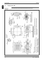
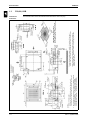
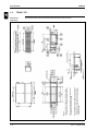
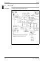
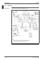
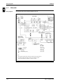
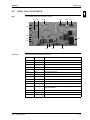
Switch Box Layout
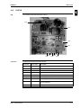
FUQ71, 100, 125B
1
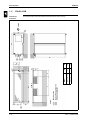
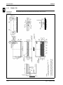
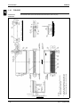
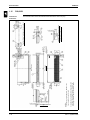
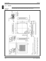
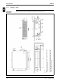
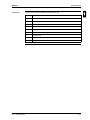
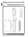
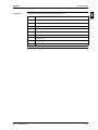
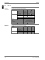
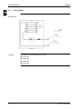
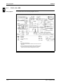
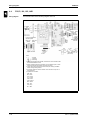
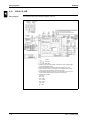
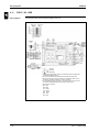
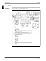
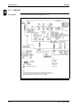
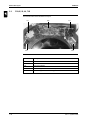
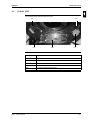
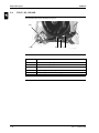
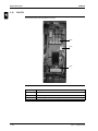
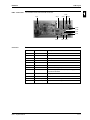
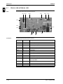
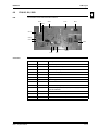
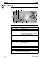
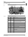
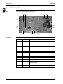
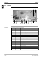
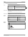
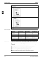
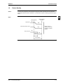
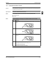
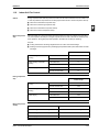
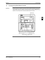
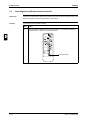
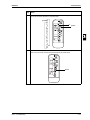
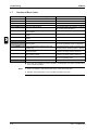
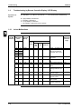
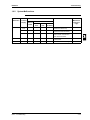
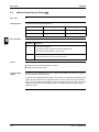
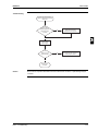
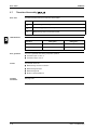
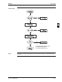
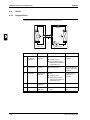
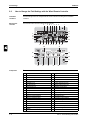
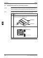
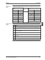
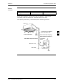
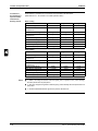
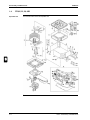
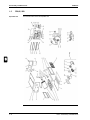
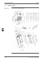
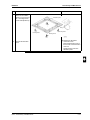
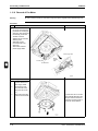
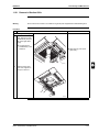
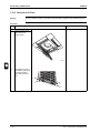
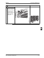
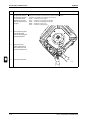
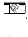
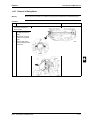
The illustration below shows the switch box layout:
PCB
T1R
3
4
X2M
X1M
C1R
5
Part 1 – System Outline
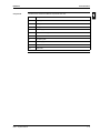
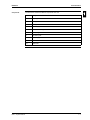
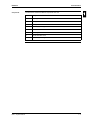
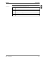
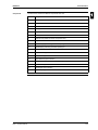
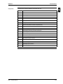
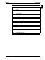
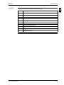
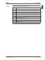
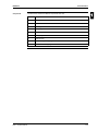
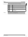
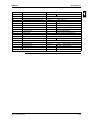
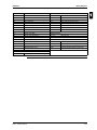
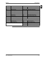
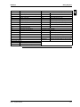
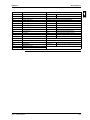
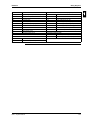
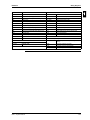
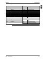
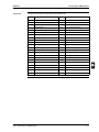
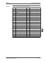
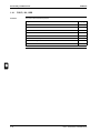
Item
Description
PCB
Printed circuit board
T1R
Transformer
C1R
Fan motor capacitor
X1M
Terminal strip (for remote control P1/P2)
X2M
Terminal strip (interconnection wiring)
1–103