1
ESIE05-04
Service Manual
R-410A Sky-Air Indoor
ESIE05-04
Table of Contents
1
1
Introduction
1.1
1.2
About This Manual ..................................................................................
Combination Overview ............................................................................
i–i
i–ii
Part 1
System Outline
1
2
3
General Outline
1.1
1.2
1.3
1.4
1.5
1.6
1.7
1.8
1.9
1.10
1.11
1.12
1.13
1.14
1.15
1.16
1.17
1.18
1.19
1.20
1.21
What Is in This Chapter? ........................................................................
FCQ35, 50, 60, 71B ................................................................................
FCQ100, 125B ........................................................................................
FCQ71D ..................................................................................................
FCQ100, 125, 140D ................................................................................
FFQ25, 35, 50, 60B ................................................................................
FBQ35, 50B ............................................................................................
FBQ60, 71B ............................................................................................
FBQ100, 125B ........................................................................................
FDQ125B ................................................................................................
FDQ200, 250B ........................................................................................
FHQ35, 50B ............................................................................................
FHQ60, 71B ............................................................................................
FHQ100B ................................................................................................
FHQ125B ................................................................................................
FUQ71B ..................................................................................................
FUQ100, 125B ........................................................................................
FAQ71B ..................................................................................................
FAQ100B ................................................................................................
FDEQ71, 100B........................................................................................
FDEQ125B..............................................................................................
1–3
1–4
1–6
1–8
1–10
1–12
1–14
1–16
1–18
1–20
1–22
1–24
1–26
1–28
1–30
1–32
1–34
1–36
1–38
1–40
1–42
2.1
2.2
2.3
2.4
2.5
2.6
2.7
2.8
2.9
2.10
What Is in This Chapter? ........................................................................
FCQ – B ..................................................................................................
FCQ – D ..................................................................................................
FFQ – B ..................................................................................................
FBQ – B ..................................................................................................
FDQ – B ..................................................................................................
FHQ – B ..................................................................................................
FUQ – B ..................................................................................................
FAQ – B ..................................................................................................
FDEQ – B................................................................................................
1–45
1–46
1–47
1–48
1–49
1–50
1–51
1–52
1–53
1–54
Specifications
Table of Contents
i
4
5
ESIE05-04
1
3
Functional Diagrams
3.1
3.2
3.3
3.4
4
4
5
5
What Is in This Chapter? .........................................................................
FCQ35, 50, 60B .......................................................................................
FCQ71, 100, 125B ...................................................................................
FCQ71, 100, 125, 140D...........................................................................
FFQ25, 35, 50, 60B .................................................................................
FBQ35, 50, 60B .......................................................................................
FBQ71B ...................................................................................................
FBQ100, 125B .........................................................................................
FDQ125, 200, 250B .................................................................................
FHQ35, 50, 60B .......................................................................................
FHQ71, 100, 125B ...................................................................................
FUQ71, 100, 125B ...................................................................................
FAQ71B ...................................................................................................
FAQ100B .................................................................................................
FDEQ71B ................................................................................................
FDEQ100B ..............................................................................................
FDEQ125B ..............................................................................................
1–61
1–62
1–64
1–66
1–68
1–70
1–72
1–74
1–76
1–78
1–80
1–82
1–84
1–86
1–88
1–90
1–92
What Is in This Chapter? .........................................................................
FCQ35, 50, 60, 71B .................................................................................
FCQ100, 125B .........................................................................................
FCQ71, 100, 125 140D............................................................................
FFQ25, 35, 50, 60B .................................................................................
FBQ35, 50, 60, 71, 100, 125B .................................................................
FDQ125, 200, 250B .................................................................................
FHQ35, 50, 60, 71, 100, 125B .................................................................
FUQ71, 100, 125B ...................................................................................
FAQ71B ...................................................................................................
FAQ100B .................................................................................................
FDEQ71, 100, 125B ................................................................................
1–95
1–96
1–97
1–98
1–99
1–100
1–101
1–102
1–103
1–104
1–105
1–106
Switch Box Layout
5.1
5.2
5.3
5.4
5.5
5.6
5.7
5.8
5.9
5.10
5.11
5.12
ii
1–55
1–56
1–58
1–59
Wiring Diagrams
4.1
4.2
4.3
4.4
4.5
4.6
4.7
4.8
4.9
4.10
4.11
4.12
4.13
4.14
4.15
4.16
4.17
3
What Is in This Chapter? .........................................................................
Indoor Piping............................................................................................
Pipe Connection Diameters .....................................................................
Piping Components .................................................................................
Table of Contents
ESIE05-04
6
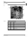
PCB Layout
1
6.1
6.2
6.3
6.4
6.5
6.6
6.7
6.8
6.9
6.10
6.11
6.12
6.13
What Is in This Chapter? ........................................................................
FCQ35, 50, 60B ......................................................................................
FCQ71, 100, 125B ..................................................................................
FCQ71, 100, 125, 140D ..........................................................................
FFQ25, 35, 50, 60B ................................................................................
FBQ35, 50, 60, 71B & FDEQ71B ...........................................................
FBQ100, 125B & FDEQ100, 125B .........................................................
FDQ125, 200, 250B ................................................................................
FHQ35, 50, 60B ......................................................................................
FHQ71, 100, 125B ..................................................................................
FUQ71, 100, 125B ..................................................................................
FAQ71B ..................................................................................................
FAQ100B ................................................................................................
1–107
1–108
1–109
1–110
1–112
1–113
1–114
1–115
1–116
1–117
1–118
1–119
1–120
3
4
5
Table of Contents
iii
ESIE05-04
1
Part 2
Functional Description
1
Functional concept
1.1
1.2
1.3
1.4
1.5
1.6
1.7
1.8
1.9
1.10
1.11
1.12
1.13
1.14
1.15
1.16
1.17
1.18
3
4
What Is in This Chapter? .........................................................................
Functions of Thermistors .........................................................................
Forced Operating Mode (Emergency Operation).....................................
Outdoor Unit Identification Function ........................................................
Simulated Operation Function .................................................................
Restart Standby .......................................................................................
Automatic Restart ....................................................................................
Using Conditions for Remote Controller Thermostat ...............................
Forced Thermostat OFF ..........................................................................
Freeze Prevention Function.....................................................................
PMV Control ...........................................................................................
Thermostat Control .................................................................................
Drain Pump Control ................................................................................
Condensation Avoidance Control ...........................................................
Draft Avoidance Control 1 .......................................................................
Draft Avoidance Control 2 .......................................................................
Fan and Flap Operations ........................................................................
Indoor Unit Fan Control ..........................................................................
2–3
2–4
2–5
2–7
2–8
2–9
2–10
2–11
2–13
2–14
2–15
2–16
2–17
2–19
2–20
2–21
2–22
2–23
5
iv
Table of Contents
ESIE05-04
Part 3
Troubleshooting
1
Troubleshooting
1.1
1.2
1.3
1.4
1.5
1.6
1.7
1.8
1.9
1.10
2
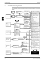
What Is in This Chapter? ........................................................................
General Troubleshooting Flowchart ........................................................
Overview of General Problems ...............................................................
Procedure of Self-Diagnosis by Remote Controller ................................
Fault-diagnosis by Wired Remote Controller ..........................................
Fault-diagnosis by Wireless Remote Controller ......................................
Overview of Error Codes.........................................................................
Troubleshooting by LED Indications on the Indoor Unit..........................
Troubleshooting by Remote Controller Display / LED Display................
Overview of the Indoor Safety Devices ..................................................
3–3
3–4
3–5
3–20
3–21
3–22
3–26
3–27
3–28
3–30
What Is in This Chapter? ........................................................................
Malfunctioning Indoor PCB ..............................................................(A1)
Malfunction of Drain Water Level System ........................................(A3)
Malfunctioning Drain System .......................................................... (AF)
Indoor Unit Fan Motor Lock .............................................................(A6)
Malfunctioning Capacity Setting .......................................................(AJ)
Thermistor Abnormality ...................................................... (C4, C5, C9)
Malfunctioning Remote Controller Air Thermistor ............................ (CJ)
Malfunctioning of Moisture Sensor System..................................... (CC)
3–31
3–32
3–33
3–35
3–36
3–38
3–40
3–42
3–43
Error Codes: System Malfunctions
3.1
3.2
3.3
3.4
3.5
3.6
Table of Contents
3
4
Error Codes
2.1
2.2
2.3
2.4
2.5
2.6
2.7
2.8
2.9
3
1
What Is in This Chapter? ........................................................................
Malfunction of Transmission between Indoor and
Outdoor Unit (U4 or UF)..........................................................................
Malfunction of Transmission between Indoor Unit and
Remote Controller (U5) ..........................................................................
Malfunction of Transmission between MAIN Remote Controller
and SUB Remote Controller
(U8)
Malfunctioning Field Setting Switch ................................................ (UA)
Centralized Address Setting Error ..................................................(UC)
3–45
3–46
3–48
3–49
3–50
3–52
v
5
ESIE05-04
1
4
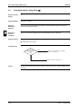
Additional Checks for Troubleshooting
4.1
4.2
4.3
4.4
4.5
4.6
4.7
4.8
What Is in This Chapter? .........................................................................
Indoor Unit: Checking the Fan Motor Hall IC ...........................................
Indoor Unit: Checking the Power Supply Wave Form..............................
Checking the Thermistors ........................................................................
Resistance Conversion Table (Ambient, Coil, Fin) .................................
Evaluation of Abnormal High Pressure ....................................................
Evaluation of Abnormal Low Pressure.....................................................
Checks .....................................................................................................
3–53
3–54
3–55
3–56
3–57
3–58
3–59
3–60
3
4
5
vi
Table of Contents
ESIE05-04
Part 4
Commissioning and Test Run
1
Pre-Test Run Checks
1.1
1.2
1.3
2
What Is in This Chapter? ........................................................................
Test Run Checks ....................................................................................
Setting the Wireless Remote Controller ..................................................
4–3
4–4
4–5
3
Field Settings
2.1
2.2
2.3
2.4
2.5
2.6
2.7
2.8
2.9
2.10
3
1
What Is in This Chapter? ........................................................................
How to Change the Field Settings with the Wired
Remote Controller ...................................................................................
How to Change the Field Settings with the Wireless
Remote Controller ...................................................................................
Overview of the Field Settings on the Indoor Units .................................
Overview of the Factory Settings on the Indoor Units.............................
Setting the Ceiling Height .......................................................................
Setting the Filter Counter ........................................................................
MAIN/SUB Setting when Using Two Remote Controllers .......................
Setting the Centralized Group No. ..........................................................
The Field Setting Levels .........................................................................
4–9
4–10
4–12
4–13
4–14
4–15
4–16
4–18
4–19
4–20
Test Run and Operation Data
3.1
Table of Contents
General Operation Data ..........................................................................
4–24
vii
4
5
ESIE05-04
1
Part 5
Disassembly and Maintenance
1
Disassembly and Maintenance
1.1
1.2
1.3
1.4
1.5
1.6
1.7
1.8
1.9
1.10
1.11
1.12
1.13
1.14
1.15
1.16
3
4
What Is in This Chapter? .........................................................................
5–3
FCQ35, 50, 60, 71B .................................................................................
5–4
FCQ100, 125B .........................................................................................
5–6
FFQ25, 35, 50, 60B .................................................................................
5–8
FBQ35, 50B ............................................................................................. 5–10
FBQ60, 71B ............................................................................................. 5–12
FBQ100, 125B ......................................................................................... 5–14
FDQ125, 200, 250B ................................................................................. 5–16
FDEQ71, 100B ........................................................................................ 5–18
FDEQ125B .............................................................................................. 5–20
FCQ71, 100, 125, 140D........................................................................... 5–22
FFQ25, 50, 60B ....................................................................................... 5–42
FHQ35, 50, 60, 71, 100, 125B ................................................................. 5–79
FUQ71, 100, 125B ................................................................................... 5–94
FAQ71B ................................................................................................... 5–111
FAQ100B ................................................................................................. 5–122
5
viii
Table of Contents
ESIE05-04
Introduction
Part 0
1
Introduction
1.1
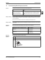
About This Manual
Target group
This service manual is intended for and should only be used by qualified engineers.
Purpose of this
manual
This service manual contains all the information you need to do the necessary repair and maintenance
tasks for the R-410A Sky Air Indoor Units.
Five parts
This service manual consists of an introduction, five parts and an index:
Introduction
overview
Part
See page
Part 1–System Outline
1–1
Part 2–Functional Description
2–1
Part 3–Troubleshooting
3–1
Part 4–Commissioning and Test Run
4–1
Part 5–Disassembly and Maintenance
5–1
4
5
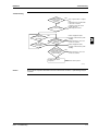
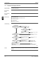
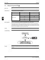
The introduction contains the following topics:
Topic
See page
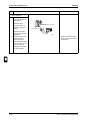
1.2–Combination Overview
ii
3
i
Introduction
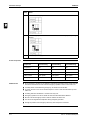
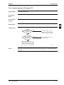
Combination Overview
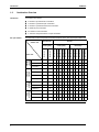
Q
“2” stands for symmetrical twin combination.
Q
“3” stands for symmetrical triple combination.
Q
“4“ stands for symmetrical double twin combination.
Q
“P” stands for pair combination
Q
‘’M’’ stands for multi combination
Q
‘’T’’ stands for assymmetrical twin or triple combination
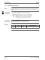
The table below contains the possible combinations between indoor units and pair split outdoor units.
Non Inverter
Inverter
950x950
cassette
standard
5
FCQ35B7V1
FCQ50B7V1
P
P
FCQ60B7V1
600X600
cassette
duct
standard
ceiling
suspended
FHQ60BUV1B
P
P
P
P
P
RXS35D(2)VMB
RXS25D(2)VMB
P
P
P
P
P
P
P
P
P
P
P
P
P
P
RSX60BVMB
P
P
P
P
RSX50BVMB
RXS35BVMB
RXS25BVMB
RKS35D(2)VMB
P
P
FHQ35BUV1B
FHQ50BUV1B
P
P
P
FBQ35B7V1
P
P
P
FBQ60B7V1
P
P
P
FFQ60B(7)V1B
FBQ50B7V1
P
P
FFQ35B(7)V1B
FFQ50B(7)V1B
Heat Pump
P
FFQ25B(7)V1B
ii
Cooling Only
RKS25BVMB
Indoor unit
RS60BVMB
4
RS50BVMB
Cooling Only
RKS25D(2)VMB
Outdoor unit
RKS60BVMB(9)
3
Pair split outdoor
In the tables in this section:
RKS50BVMB(9)
Introduction
RKS35BVMB
1
1.2
ESIE05-04
P
P
P
P
P
ESIE05-04
The table below contains the possible combinations between indoor units and multi split outdoor units.
Inverter
Outdoor unit
4MKS75BVMB
4MKS90BVMB
4MKS58DVMB
4MKS75DVMB
4MKS90DVMB
3MXS52BVMB
4MXS68BVMB
4MXS80BVMB
2MXS52DVMB
3MXS52DVMB
4MXS68DVMB
4MXS80DVMB
RMXS112D7V3B
RMXS140D7V3B
RMXS160D7V3B
FCQ35B7V1
M
M
M
M
M
M
M
M
M
M
M
M
M
M
M
M
FCQ50B7V1
M
M
M
M
M
M
M
M
M
M
M
M
M
M
M
M
M
M
M
M
M
M
M
M
M
M
M
600X600
cassette
950x950
cassette
standard
Indoor unit
FCQ60B7V1
FFQ25B(7)V1B
M
M
M
M
M
M
M
M
M
M
M
M
M
M
M
M
FFQ35B(7)V1B
M
M
M
M
M
M
M
M
M
M
M
M
M
M
M
M
FFQ50B(7)V1B
M
M
M
M
M
M
M
M
M
M
M
M
M
M
M
M
M
M
M
M
M
M
M
M
M
M
M
FFQ60B(7)V1B
duct
standard
Heat Pump
4MKS58BVMB
Cooling Only
ceiling
suspended
Multi split outdoor
Introduction
FBQ35B7V1
M
M
M
M
M
M
M
M
M
M
M
M
M
M
M
M
FBQ50B7V1
M
M
M
M
M
M
M
M
M
M
M
M
M
M
M
M
M
M
M
M
M
M
M
M
M
M
M
FBQ60B7V1
FHQ35BUV1B
M
M
M
M
M
M
M
M
M
M
M
M
M
M
M
M
FHQ50BUV1B
M
M
M
M
M
M
M
M
M
M
M
M
M
M
M
M
M
M
M
M
M
M
M
M
M
M
M
FHQ60BUV1B
iii
3
4
5
Introduction
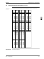
The table below contains the possible combinations between indoor units and Sky Air outdoor units.
Non Inverter
FCQ35B7V1
5
T
T
T
T
T
FCQ60B7V1
T
T
T
T
T
T
T
T
P
P
P
FCQ125B7V3B
P
4
4
2
3
3
P
P
P
2
P
600X600
standard
large
duct
P
T
T
T
2
T
T
T
T
FFQ60B(7)V1B
T
T
T
T
T
T
2
T
T
T
T
FBQ60B7V1
T
T
T
T
T
T
T
T
P
P
P
P
P
FDQ125B7V3B
P
P
P
SC30 duct
3
3
4
3
3
4
4
2
3
3
4
3
2
4
4
3
2
P
2
P
2
P
FDQ250B7V3B
iv
2
P
FDQ200B7V3B
FDEQ125B7V3B
4
P
P
P
4
2
P
FBQ125B7V3B
3
2
T
FBQ50B7V1
FDEQ100B7V3B
RZQ250B7W1B
P
FFQ50B(7)V1B
FDEQ71B7V3B
2
P
FCQ140DV3B
FBQ100B7V3B
RZQ200B7W1B
2
P
FCQ125DV3B
FBQ71B7V3B
4
3
P
FCQ100DV3B
FBQ35B7V1
4
3
P
FCQ71DV3B
FFQ35B(7)V1B
RZQ140B7W1B
RZQ125B7(8)V3B
RZQ125B7W1B
RZQ100B7(8)V3B
RZQ100B7W1B
3
2
P
P
RZQ71B7(8)V3B
2
T
FCQ71B7V3B
Heat Pump
REQ125B7W1B
RQ100B7V3B
RQ100B7W1B
RQ71B7V3B
RQ71B7W1B
RR125B7W1B
T
Heat Pump
FCQ50B7V1
FCQ100B7V3B
high COP
4
standard
950x950 cassette
3
T
RR100B7V3B
RR100B7W1B
Indoor unit
RR71B7V3B
RR71B7W1B
Cooling Only
Inverter
REQ100B7V3B
REQ100B7W1B
Outdoor unit
REQ71B7V3B
REQ71B7W1B
Sky Air outdoor
RQ125B7W1B
1
ESIE05-04
P
P
P
P
Wall
mounted
ceiling
suspended
cassette
ceiling suspended
Indoor unit
FHQ35BUV1B
FHQ71BUV3B
FUQ71BV3B
FAQ71BV3B
FAQ100BV3B
T
FHQ50BUV1B
T
T
T
T
FHQ60BUV1B
T
T
T
T
T
T
T
T
P
FHQ100BUV3B
P
FUQ100BV3B
P
FHQ125BUV3B
T
FUQ125BV3B
T
P
T
T
T
T
P
P
P
P
P
P
P
P
T
P
T
P
T
T
T
P
2
P
P
3
4
4
2
3
3
P
P
P
P
P
RZQ250B7W1B
RZQ200B7W1B
Heat Pump
RZQ140B7W1B
Non Inverter
RZQ125B7(8)V3B
RZQ125B7W1B
RZQ100B7(8)V3B
RZQ100B7W1B
RZQ71B7(8)V3B
REQ125B7W1B
REQ100B7V3B
REQ100B7W1B
REQ71B7V3B
REQ71B7W1B
Cooling Only
RQ125B7W1B
RQ100B7V3B
RQ100B7W1B
RQ71B7V3B
RQ71B7W1B
RR125B7W1B
RR100B7V3B
RR100B7W1B
RR71B7V3B
RR71B7W1B
ESIE05-04
Introduction
Outdoor unit
Inverter
Heat Pump
2
2
3
P
P
2
4
P
P
2
P
5
v
Introduction
1
ESIE05-04
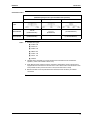
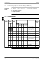
Combination matrix
Possible indoor combination
(Standard capacity for twin, triple and double twin operation)
Twin
Triple
Double Twin
Outdoor
models
3
RZQ71B8V3B
35-35
(KHRQ22M20TA7)
RZQ100B8V3B
RZQ100B7W1B
50-50
(KHRQ22M20TA7)
35-35-35
(KHRQ127H7)
RZQ125B8V3B
RZQ125B7W1B
60-60
(KHRQ22M20TA7)
50-50-50
(KHRQ127H7)
35-35-35-35
(3x KHRQ22M20TA7)
RZQ140B7W1B
71-71
(KHRQ22M20TA7)
50-50-50
(KHRQ127H7)
35-35-35-35
(3x KHRQ22M20TA7)
4
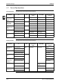
Notes:
1
5
vi
Possible indoor types:
Q
FCQ35~71
Q
FFQ35~60
Q
FHQ35~71
Q
FBQ35~71
Q
FUQ71
Q
FAQ71
2
Individual indoor capacities are not given because the combinations are for simultaneous
operation (=indoor units installed in same room).
3
When different indoor models are used in combination, designate the remote controller that is
equipped with the most functions as the main unit. In note 1 are the indoor units mentioned in order
of the possible function (most functions are on FCQ, less functions are on FAQ)
4
Between brackets are the required Refnet kits mentioned, that are necessary to install the
combination
ESIE05-04
Introduction
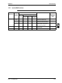
Combination matrix
Possible indoor combination
(Standard capacity for twin, triple and double twin operation)
Twin
Triple
Double Twin
RZQ200B7W1B
100-100
(KHRQ22M20TA7)
60-60-60
71-71-71
(KHRQ250H7)
50-50-50-50
(3x KHQ22M20TA7)
RZQ250B7W1B
125-125
(KHRQ22M20TA7)
_
60-60-60-60
(3x KHRQ22M20TA7)
Outdoor
models
Notes:
1
3
Possible indoor types:
Q
FCQ50~125
Q
FFQ50, 60
Q
FHQ50~125
Q
FBQ50~125
Q
FUQ71~125
Q
FAQ71, 100
Q
FDQ125
4
5
2
Individual indoor capacities are not given because the combinations are for simultaneous
operation (=indoor units installed in same room).
3
When different indoor models are used in combination, designate the remote controller that is
equipped with the most functions as the main unit. In note 1 are the indoor units mentioned in order
of the possible function (most functions are on FCQ, less functions are on FAQ)
4
Between brackets are the required Refnet kits mentioned, that are necessary to install the
combination
vii
Introduction
1
ESIE05-04
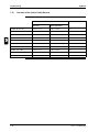
Combination matrix
Possible indoor combination
(Standard capacity for twin and triple operation)
Twin
Triple
Outdoor
models
3
RQ71B7V3/W1
RR71B7V3/W1
35-35
(KHRQ22M20TA7)
_
_
RQ100B7V3/W1
RR100B7V3/W1
50-50
(KHRQ22M20TA7)
50-60
(KHRQ22M20TA7)
RQ125B7W1
RR125B7W1
60-60
(KHRQ22M20TA7)
50-71
(KHRQ22M20TA7)
Notes:
1
4
5
viii
_
_
_
_
35-71
(KHRQ22M20TA7)
35-35-35
(KHRQ127H7)
_
_
_
_
50-50-50
(KHRQ127H7)
_
_
_
Possible indoor types:
Q
FCQ35~71
Q
FFQ35~60
Q
FUQ71
Q
FHQ35~71
Q
FAQ71
Q
FBQ35~71
2
Individual indoor capacities are not given because the combinations are for simultaneous
operation (=indoor units installed in same room).
3
When different indoor models are used in combination, designate the remote controller that is
equipped with the most functions as the main unit. In note 1 are the indoor units mentioned in order
of the possible function (most functions are on FCQ, less functions are on FBQ)
4
Between brackets are the required Refnet kits mentioned, that are necessary to install the
combination
5
For unit specification of the outdoor units and the indoor units refer to the unit specifications
mentioned for pair systems.
6
Nominal cooling capacities are based on the following conditions: indoor air temperature: 27°CDB,
19°CWB, outdoor temperature 35°CDB. Nominal heating capacities are based on the following
conditions: indoor air temperature: 20°CDB, outdoor temperature 7°CDB, 6°CWB.
ESIE05-04
1
4
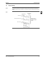
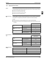
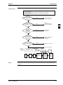
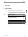
Part 1
System Outline
What is in this part?
3
This part contains the following chapters:
Chapter
See page
1–General Outline
1–3
2–Specifications
1–45
3–Functional Diagrams
1–55
4–Wiring Diagrams
1–61
5–Switch Box Layout
1–95
6–PCB Layout
1–107
4
5
Part 1 – System Outline
1–1
ESIE05-04
11
3
5
1–2
Part 1 – System Outline
ESIE05-04
General Outline
Part 1
1
1
General Outline
1.1
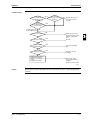
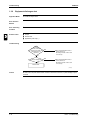
What Is in This Chapter?
Introduction
General outline
Part 1 – System Outline
This chapter contains the following information on the indoor units:
Q
Outlook and dimensions
Q
Components
3
This chapter contains the following general outlines:
General outline
See page
1.2–FCQ35, 50, 60, 71B
1–4
1.3–FCQ100, 125B
1–6
1.4–FCQ71D
1–8
1.5–FCQ100, 125, 140D
1–10
1.6–FFQ25, 35, 50, 60B
1–12
1.7–FBQ35, 50B
1–14
1.8–FBQ60, 71B
1–16
1.9–FBQ100, 125B
1–18
1.10–FDQ125B
1–20
1.11–FDQ200, 250B
1–22
1.12–FHQ35, 50B
1–24
1.13–FHQ60, 71B
1–26
1.14–FHQ100B
1–28
1.15–FHQ125B
1–30
1.16–FUQ71B
1–32
1.17–FUQ100, 125B
1–34
1.18–FAQ71B
1–36
1.19–FAQ100B
1–38
1.20–FDEQ71, 100B
1–40
1.21–FDEQ125B
1–42
4
5
1–3
see note 3
1–4
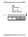
2. When installing an optional accessory, refer to the installation drawings.
- For the fresh air intake kit ..... an inspection port is necessary
- For the high efficiency filter ..... an inspection port is necessary
- For the branch duct chamber .... an inspection port is necessary
(Ceiling opening)
Branch duct
connection
Prepared hole
(Suspension position)
mo
re
or
mo
re
Branch duct
connection
Prepared hole
or
mo
re
VIEW D
REQUIRED INSTALLATION SPACE
WHEN THE DISCHARGE GRILL IS CLOSED,
THE REQUIRED SPACE IS 200 mm OR MORE.
or
VIEW B
Branch duct
connection
4. When the conditions exceed 30°C and RH 80% in the ceiling or fresh air is
inducted into the ceiling, an additional insulation is required (polyethylene foam,
thickness 10mm or more).
3. In case of using a wireless remote controller, this position will be a signal
receiver. Refer to the drawing of the wireless remote controller for more details.
or less
(Ceiling opening)
5
(Suspension position)
4
NOTES:
1. Location of the nameplates:
- Unit body: on the bell mouth at the inside of the suction grill.
- Decoration panel: on the panel frame at the inside of the suction grill.
VIEW C
Prepared hole
3
Hanging bolt
VIEW A
Prepared hole
or
mo
re
Outlook and
dimensions
Adjustable
1.2
or more
Installation space
11
For fresh air intake kit
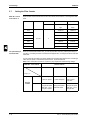
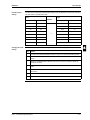
connection (direct
installation type)
General Outline
ESIE05-04
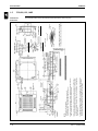
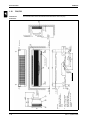
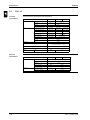
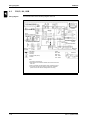
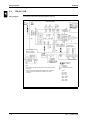
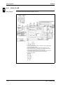
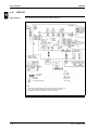
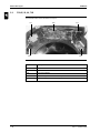
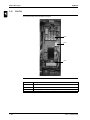
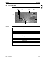
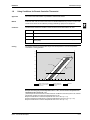
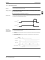
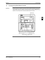
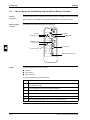
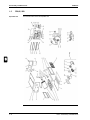
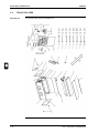
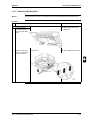
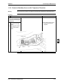
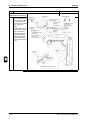
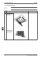
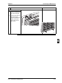
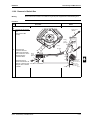
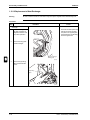
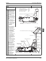
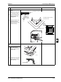
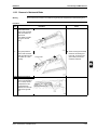
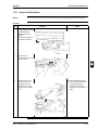
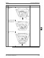
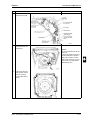
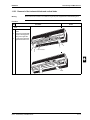
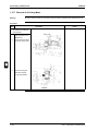
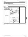
FCQ35, 50, 60, 71B
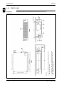
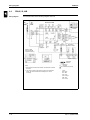
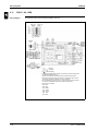
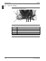
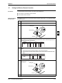
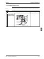
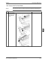
The illustration below shows the outlook and the dimensions of the unit (mm).
Part 1 – System Outline
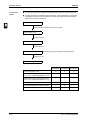
ESIE05-04
Components
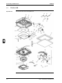
General Outline
1
The table below contains the different components of the unit.
No.
Component
1
Liquid pipe connection
2
Gas pipe connection
3
Drain pipe connection
4
Power supply connection
5
Transmission wiring connection
6
Air outlet
7
Air suction grille
8
Water supply intake for drain
9
Corner decoration cover
10
Drain hose
3
4
5
Part 1 – System Outline
1–5
1–6
see note 3
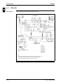
2. When installing an optional accessory, refer to the installation drawings.
- For the fresh air intake kit ..... an inspection port is necessary
- For the high efficiency filter ..... an inspection port is necessary
- For the branch duct chamber .... an inspection port is necessary
NOTES:
1. Location of the nameplates:
- Unit body: on the bell mouth at the inside of the suction grill.
- Decoration panel: on the panel frame at the inside of the suction grill.
Branch duct
connection
Prepared hole
Branch duct
connection
Prepared hole
(Suspension position)
(Ceiling opening)
or
VIEW B
re
m
or
o re
or
mo
Branch duct
connection
Prepared hole
re
or
mo
re
VIEW D
or
mo
REQUIRED INSTALLATION SPACE
WHEN THE DISCHARGE GRILL IS CLOSED,
THE REQUIRED SPACE IS 200 mm OR MORE.
mo
Prepared hole
Branch duct
connection
4. When the conditions exceed 30°C and RH 80% in the ceiling or fresh air is
inducted into the ceiling, an additional insulation is required (polyethylene foam,
thickness 10mm or more).
3. In case of using a wireless remote controller, this position will be a signal
receiver. Refer to the drawing of the wireless remote controller for more details.
(Suspension position)
4
Hanging bolt
VIEW A
or less
5
(Ceiling opening)
3
VIEW C
Prepared hole
re
Outlook and
dimensions
Adjustable
1.3
or more
Installation space
11
For fresh air intake kit
connection (direct
installation type)
General Outline
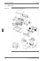
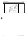
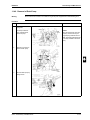
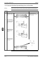
ESIE05-04
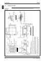
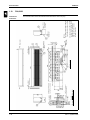
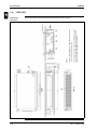
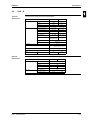
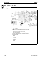
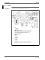
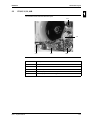
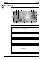
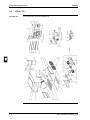
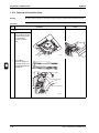
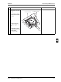
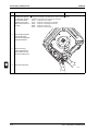
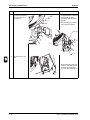
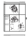
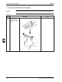
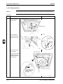
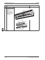
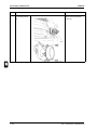
FCQ100, 125B
The illustration below shows the outlook and the dimensions of the unit (mm).
Part 1 – System Outline
ESIE05-04
Components
General Outline
1
The table below contains the different components of the unit.
No.
Component
1
Liquid pipe connection
2
Gas pipe connection
3
Drain pipe connection
4
Power supply connection
5
Transmission wiring connection
6
Air discharge outlet
7
Air suction grille
8
Water supply intake for drain
9
Corner decoration cover
10
Drain hose
3
4
5
Part 1 – System Outline
1–7
1–8
Adjustable (0~550)
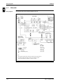
35 or less
4. Though the installation is acceptable up to maximum of 910mm square ceiling
opening, keep the clearance of 35mm or less between the main unit and the
ceiling opening so that the panel overlap allowance can be ensured.
3. When the temperature and humidity in the ceiling exceed 30°C and RH 80% or
the fresh air is inducted into the ceiling or the unit continues 24 hour operation,
an additional insulation (thickness 10mm or more of glasswool or polyethylene
form) is required.
2. In case of using wireless remote controller, this position will be a signal receiver.
Refer to the drawing of wireless remote controller for detail.
NOTES:
1. Location of unit’s name plate
for indoor unit : on the bell mouth inside suction grill
for decoration panel : on the inner frame inside suction grill
Suspension bolt
Branch duct
connection
hole
860-910 (Ceiling opening space)(Note 4)
780 (Suspension position)
35 or less
(Note 4)
Branch duct
connection
Branch duct
connection
*
1500mm
or more
*
D ARROW VIEW
*WHEN THE DISCHARGE GRILL IS
CLOSED, THE REQUIRED SPACE IS
200mm OR MORE.
*
*
1500mm
or more
1500mm or more
1500mm or more
•REQUIRED SPACE
C ARROW VIEW
Outdoor air intake
(Direct connection)
Branch duct
connection
12-M4 hole
12-M4 hole
4-M4 hole
B ARROW VIEW
4
12-M4 hole
5
860~910 (Ceiling opening space) (Note 4)
680 (Suspension position)
3
Pipe connection
side
Drain connection
side
300
or less
Outlook and
dimensions
1500 or more
(Required space)
From
the floor side 2500 or more
1.4
FOR HEIGHT INSTALLATION
11
(Note 2)
General Outline
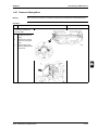
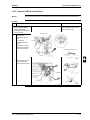
ESIE05-04
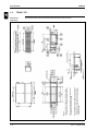
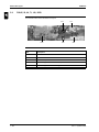
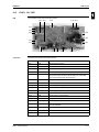
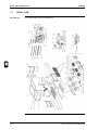
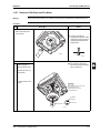
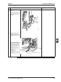
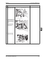
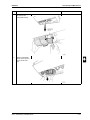
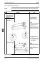
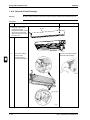
FCQ71D
The illustration below shows the outlook and the dimensions of the unit (mm).
Part 1 – System Outline
ESIE05-04
Components
General Outline
1
The table below contains the different components of the unit.
No.
Component
1
Liquid pipe connection
2
Gas pipe connection
3
Drain pipe connection
4
Power supply / Wiring / Remote controller connection
5
Air outlet
6
Suction grille
7
Corner decoration cover
8
Drain hose (accessory)
3
4
5
Part 1 – System Outline
1–9
1–10
Adjustable (0~055)
35 or less
4. Though the installation is acceptable up to maximum of 910mm square ceiling
opening, keep the clearance of 35mm or less between the main unit and the
ceiling opening so that the panel overlap allowance can be ensured.
3. When the temperature and humidity in the ceiling exceed 30°C and RH 80% or
the fresh air is inducted into the ceiling or the unit continues 24 hour operation,
an additional insulation (thickness 10mm or more of glasswool or polyethylene
form) is required.
2. In case of using wireless remote controller, this position will be a signal receiver.
Refer to the drawing of wireless remote controller for detail.
NOTES:
1. Location of unit’s name plate
for indoor unit : on the bell mouth inside suction grill
for decoration panel : on the inner frame inside suction grill
Suspension bolt
12-M4 hole
Branch duct
connection
860~910 (Ceiling opening space)(Note 4)
780 (Suspension position)
35 or less
(Note 4).
Branch duct
connection
12-M4 hole
4
*
*
more
*
1500mm or
1500mm or more
*
*WHEN THE DISCHARGE GRILL IS CLOSED,
THE REQUIRED SPACE IS 200 mm OR MORE.
or more
1500mm
1500mm or more
•REQUIRED SPACE
C ARROW VIEW
D ARROW VIEW
Branch duct
connection
12-M4 hole
Outdoor air intake
(Direct connection)
4-M4 hole
B ARROW VIEW
Branch duct
connection
12-M4 hole
3
Pipe connection
side
Drain connection
side
5
860~910 (Ceiling opening space) (Note 4)
300
or less
680 (Suspension position)
Outlook and
dimensions
1500 or more
(Required space)
From
the floor side 2500 or
1.5
FOR HEIGHT INSTALLATION
11
(Note 2)
General Outline
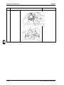
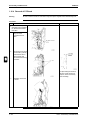
ESIE05-04
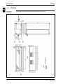
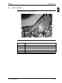
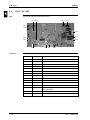
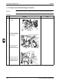
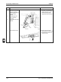
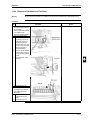
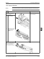
FCQ100, 125, 140D
The illustration below shows the outlook and the dimensions of the unit (mm).
Part 1 – System Outline
ESIE05-04
Components
General Outline
1
The table below contains the different components of the unit.
No.
Component
1
Liquid pipe connection
2
Gas pipe connection
3
Drain pipe connection
4
Power supply / Wiring / Remote controller connection
5
Power supply connection
6
Air-Outlet
7
Suction grille
8
Corner decoration cover
9
Drain hose (accessory)
3
4
5
Part 1 – System Outline
1–11
1–12
Adjustable
4. Though the installation is acceptable up to maximum of 910mm square ceiling
opening, keep the clearance of 35mm or less between the main unit and the
ceiling opening so that the panel overlap allowance can be ensured.
3. When the temperature and humidity in the ceiling exceed 30°C and RH 80% or
the fresh air is inducted into the ceiling or the unit continues 24 hour operation,
an additional insulation (thickness 10mm or more of glasswool or polyethylene
form) is required.
2. In case of using wireless remote controller, this position will be a signal receiver.
Refer to the drawing of wireless remote controller for detail.
NOTES:
1. Location of unit’s name plate
for indoor unit : on the bell mouth inside suction grill
for decoration panel : on the inner frame inside suction grill
or less
or less
(Note 4).
*
*
or more
*
or more
Outdoor air intake
(Direct connection)
Ceiling
*WHEN THE DISCHARGE GRILL IS CLOSE, THE
REQUIRED SPACE IS 200 mm OR MORE.
or more
or more
B ARROW VIEW
•REQUIRED SPACE
hole
3
Suspension bolt
A ARROW VIEW
Pipe connection side
Drain connection side
(Note 2)
(Ceiling opening space)
(Suspension position)
*
Outlook and
dimensions
(Suspension position)
or more
(Required space)
4
or more
(Ceiling opening space)
5
1.6
From the floor side
or more
FOR HEIGHT INSTALLATION
11
or less
General Outline
ESIE05-04
FFQ25, 35, 50, 60B
The illustration below shows the outlook and the dimensions of the unit (mm).
Part 1 – System Outline
ESIE05-04
Components
General Outline
1
The table below contains the different components of the unit.
No.
Component
1
Liquid pipe connection
2
Gas pipe connection
3
Drain pipe connection
4
Power supply connection
5
Remote control code and control wiring connection
6
Air discharge outlet
7
Suction grille
8
Drain hose
3
4
5
Part 1 – System Outline
1–13
1–14
3. For maintenance of the air filter, it is necessary to
provide a service access panel according to the
installation method. (Refer to the ‘Filter installation
method’ drawing)
2. The required ceiling depth varies according to the
configuration of the specific system.
(On circumference)
(Knock out hole)
VIEW C
P.C.D.
Fresh air intake position
5
NOTES:
1. Refer to ‘Outlook drawing for installing optional
accessories’ when installing optional accessories.
(Service Space)
3
or more
(Suspension bolt)
Outlook and
dimensions
(Air suction panel center)
VIEW B
1.7
VIEW A
11
(Suspension position)
General Outline
ESIE05-04
FBQ35, 50B
The illustration below shows the outlook and the dimensions of the unit (mm).
4
Part 1 – System Outline
ESIE05-04
Components
General Outline
1
The table below contains the different components of the unit.
No.
Component
1
Liquid pipe connection
2
Gas pipe connection
3
Drain pipe connection
4
Remote controller wiring connection
5
Power supply connection
6
Drain hole
7
Air filter
8
Air suction side
9
Air discharge side
10
Nameplate
3
4
5
Part 1 – System Outline
1–15
1–16
3. For maintenance of the air filter, it is necessary to
provide a service access panel according to the
installation method. (Refer to the ‘Filter installation
method’ drawing)
(On circumference)
(Knock out hole)
VIEW C
Fresh air intake position
5
2. The required ceiling depth varies according to the
configuration of the specific system.
P.C.D.
4
NOTES:
1. Refer to ‘Outlook drawing for installing optional
accessories’ when installing optional accessories.
(Service Space)
(Air suction panel center)
Outlook and
dimensions
or more
(Suspension bolt)
3
VIEW B
1.8
VIEW A
11
(Suspension position)
General Outline
ESIE05-04
FBQ60, 71B
The illustration below shows the outlook and the dimensions of the unit (mm).
Part 1 – System Outline
ESIE05-04
Components
General Outline
1
The table below contains the different components of the unit.
No.
Component
1
Liquid pipe connection
2
Gas pipe connection
3
Drain pipe connection
4
Remote controller wiring connection
5
Power supply connection
6
Drain hole
7
Air filter
8
Air suction side
9
Air discharge side
10
Nameplate
3
4
5
Part 1 – System Outline
1–17
1–18
3. For maintenance of the air filter, it is necessary to
provide a service access panel according to the
installation method. (Refer to the ‘Filter installation
method’ drawing)
2. The required ceiling depth varies according to the
configuration of the specific system.
(On circumference)
(Knock out hole)
P.C.D.
5
VIEW C
Fresh air intake position
(Service Space)
or more
Suspension bolt
4
VIEW B
Outlook and
dimensions
VIEW A
1.9
NOTES:
1. Refer to ‘Outlook drawing for installing optional
accessories’ when installing optional accessories.
(Suspension position)
11
(Suspension position)
General Outline
ESIE05-04
FBQ100, 125B
The illustration below shows the outlook and the dimensions of the unit (mm).
3
Part 1 – System Outline
or more
(Installation Space)
ESIE05-04
Components
General Outline
1
The table below contains the different components of the unit.
No.
Component
1
Liquid pipe connection
2
Gas pipe connection
3
Drain pipe connection
4
Remote controller wiring connection
5
Power supply connection
6
Drain hole
7
Air filter
8
Air suction side
9
Air discharge side
10
Nameplate
3
4
5
Part 1 – System Outline
1–19
General Outline
11
1.10
ESIE05-04
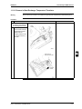
FDQ125B
The illustration below shows the outlook and the dimensions of the unit (mm).
VIEW A
Outlook and
dimensions
3
4
NOTE:
SERVICE SPACE
VIEW A
5
1–20
Part 1 – System Outline
ESIE05-04
Components
General Outline
1
The table below contains the different components of the unit.
No.
Component
1
Power supply instake
2
Drain connection
3
Gas pipe connection single union
4
Liquid pipe connection single union
5
Filter
3
4
5
Part 1 – System Outline
1–21
General Outline
11
1.11
ESIE05-04
FDQ200, 250B
The illustration below shows the outlook and the dimensions of the unit (mm).
VIEW A
Outlook and
dimensions
3
4
1–22
255
890
FDQ250B7V3B
285
830
FDQ200B7V3B
EXTRA SERVICE SPACE FOR
OPTIONAL DRAINPUMP
SERVICE SPACE
NOTES:
VIEW A
Model
A
B
5
Part 1 – System Outline
ESIE05-04
Components
General Outline
1
The table below contains the different components of the unit.
No.
Component
1
Power supply instake
2
Drain connection
3
Gas pipe connection
4
Liquid pipe connection
5
Filter
3
4
5
Part 1 – System Outline
1–23
1–24
(Required space)
Drain pipe
connection
(For left piping)
(Required space)
For height installation
2. In case of using wireless remote controller, this
position will be a signal receiver. Refer to the
drawing of wireless remote controller for detail.
The front
(Hanging position)
or more
Brand name plate
(Note 2)
(Service Space)
5
NOTES:
1. Location of unit’s Name plate: Bottom of fan
housing inside the suction grill.
Floor side
Obstacle
(Hanging position)
or more
(Service Space)
Hanging bolt
4
or more
3
From the floor side
Position of the hole in the wall for
piping straight trough the wall
(View from the front)
Outlook and
dimensions
or more
1.12
(Required space)
11
Position slit hole for taking out in piping back
(View from the front)
General Outline
ESIE05-04
FHQ35, 50B
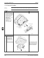
The illustration below shows the outlook and the dimensions of the unit (mm).
Part 1 – System Outline
ESIE05-04
Components
Part 1 – System Outline
General Outline
1
The table below contains the different components of the unit.
No.
Component
1
Air outlet
2
Air suction grille
3
Air filter
4
Gas pipe connection
5
Liquid pipe connection
6
Drain pipe connection
7
Earth terminal (Inside the electric components box)
8
Suspension bracket
9
Backward piping and wiring connection opening lid
10
Upward piping and wiring connection opening lid
11
Right side pipe connection
12
Back side drain pipe connection, left
13
Left side drain pipe connection
14
Right side drain pipe connection
15
Position of the hole in the wall for piping straight trough the wall
16
Upward drain pipe connection
17
Upward gas pipe connection
18
Upward liquid pipe connection
3
4
5
1–25
1–26
Drain pipe
connection
(For left piping)
(Required space)
or more
From the floor side 2500 or more
(Required space)
For height installation
2. In case of using wireless remote controller, this
position will be a signal receiver. Refer to the
drawing of wireless remote controller for detail.
Brand name plate
(Note 2)
4
Floor side
The front
or more
(Service Space)
3
NOTES:
1. Location of unit’s Name plate: Bottom of fan
housing inside the suction grill.
Obstacle
(Hanging position)
Position of the hole in the wall for
piping straight trough the wall
(View from the front)
Outlook and
dimensions
(Hanging position)
or more
(Service Space)
Hanging bolt
1.13
(Required space)
11
Position slit hole for taking out in piping back
(View from the front)
General Outline
ESIE05-04
FHQ60, 71B
The illustration below shows the outlook and the dimensions of the unit (mm).
5
Part 1 – System Outline
ESIE05-04
Components
Part 1 – System Outline
General Outline
1
The table below contains the different components of the unit.
No.
Component
1
Air outlet
2
Air suction grille
3
Air filter
4
Gas pipe connection
5
Liquid pipe connection
6
Drain pipe connection
7
Earth terminal (Inside the electric components box)
8
Suspension bracket
9
Backward piping and wiring connection opening lid
10
Upward piping and wiring connection opening lid
11
Right side pipe connection
12
Back side drain pipe connection, left
13
Left side drain pipe connection
14
Right side drain pipe connection
15
Position of the hole in the wall for piping straight trough the wall
16
Upward drain pipe connection
17
Upward gas pipe connection
18
Upward liquid pipe connection
3
4
5
1–27
1–28
(Required space)
or more
Floor side
Drain pipe
connection
(For left piping)
(Hanging position)
For height installation
From the floor side 2500 or more
(Required space)
2. In case of using wireless remote controller, this
position will be a signal receiver. Refer to the
drawing of wireless remote controller for detail.
The front
4
Brand name plate
(Note 2)
or more
(Service Space)
3
NOTES:
1. Location of unit’s Name plate: Bottom of fan
housing inside the suction grill.
Obstacle
(Hanging position)
Position of the hole in the wall for
piping straight trough the wall
(View from the front)
Outlook and
dimensions
or more
(Service Space)
Hanging bolt
1.14
(Required space)
11
Position slit hole for taking out in piping back
(View from the front)
General Outline
ESIE05-04
FHQ100B
The illustration below shows the outlook and the dimensions of the unit (mm).
5
Part 1 – System Outline
ESIE05-04
Components
Part 1 – System Outline
General Outline
1
The table below contains the different components of the unit.
No.
Component
1
Air outlet
2
Air suction grille
3
Air filter
4
Gas pipe connection
5
Liquid pipe connection
6
Drain pipe connection
7
Earth terminal (Inside the electric components box)
8
Suspension bracket
9
Backward piping and wiring connection opening lid
10
Upward piping and wiring connection opening lid
11
Right side pipe connection
12
Back side drain pipe connection, left
13
Left side drain pipe connection
14
Right side drain pipe connection
15
Position of the hole in the wall for piping straight trough the wall
16
Upward drain pipe connection
17
Upward gas pipe connection
18
Upward liquid pipe connection
3
4
5
1–29
1–30
(Required space)
or more
Floor side
Drain pipe
connection
(For left piping)
(Hanging position)
or more
(Required space)
For height installation
2. In case of using wireless remote controller, this
position will be a signal receiver. Refer to the
drawing of wireless remote controller for detail.
The front
Brand name plate
(Note 2)
or more
(Service Space)
4
NOTES:
1. Location of unit’s Name plate: Bottom of fan
housing inside the suction grill.
Obstacle
(Hanging position)
3
or more
(Service Space)
Hanging bolt
Position of the hole in the wall for
piping straight trough the wall
(View from the front)
Outlook and
dimensions
From the floor side
1.15
(Required space)
11
Position slit hole for taking out in piping back
(View from the front)
General Outline
ESIE05-04
FHQ125B
The illustration below shows the outlook and the dimensions of the unit (mm).
5
Part 1 – System Outline
ESIE05-04
Components
Part 1 – System Outline
General Outline
1
The table below contains the different components of the unit.
No.
Component
1
Air outlet
2
Air suction grille
3
Air filter
4
Gas pipe connection
5
Liquid pipe connection
6
Drain pipe connection
7
Earth terminal (Inside the electric components box)
8
Suspension bracket
9
Backward piping and wiring connection opening lid
10
Upward piping and wiring connection opening lid
11
Right side pipe connection
12
Back side drain pipe connection, left
13
Left side drain pipe connection
14
Right side drain pipe connection
15
Position of the hole in the wall for piping straight trough the wall
16
Upward drain pipe connection
17
Upward gas pipe connection
18
Upward liquid pipe connection
3
4
5
1–31
1–32
3. When closing the discharge grill (2 or 3 way discharge), direction of
pipe connecion will be limited, please refer to Installation manual.)
discharge grill, the
required space is 30mm
or more. (Note 3)
*
or more
or more
*When closing the
Height of suspension bracket
*
or more
Suspension bolt
*
or more
or more
(Required space)
4
2.In case of using wireless remote controller, this is the position for the
signal receiver. Refer to the drawing of wireless remote controller
for detail.
NOTES:
1. Location of unit’s name plate: on bell mouth.
be raised up to 350mm from the top surface of the product.
Brand name plate ( Note 2)
3
Required space
*
Outlook and
dimensions
*Drain pipe can
Drain
connection
location for rear
piping
1.16
Suspension position
11
Drain
connection
location for
upwards piping
General Outline
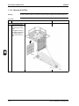
ESIE05-04
FUQ71B
The illustration below shows the outlook and the dimensions of the unit (mm).
5
Part 1 – System Outline
ESIE05-04
Components
General Outline
1
The table below contains the different components of the unit.
No.
Component
1
Liquid pipe connection
2
Gas pipe connection
3
Drain pipe connection
4
Air outlet
5
Air suction grille
6
Corner decoration cover
7
Right pipe and wiring connection
8
Rear pipe and wiring connection
9
Cover for upwards pipe and wiring connection
10
Accessory drain elbow
3
4
5
Part 1 – System Outline
1–33
1–34
3. When closing the discharge grill (2 or 3 way discharge), direction of
pipe connecion will be limited, please refer to Installation manual.)
discharge grill, the
required space is 30mm
or more. (Note 3)
*
or more
or more
*When closing the
Height of suspension bracket
*
or more
Suspension bolt
*
or more
or more
(Required space)
4
2.In case of using wireless remote controller, this is the position for the
signal receiver. Refer to the drawing of wireless remote controller
for detail.
NOTES:
1. Location of unit’s name plate: on bell mouth.
Brand name plate ( Note 2)
be raised up to 350mm from the top surface of the product.
3
Required space
*
Outlook and
dimensions
*Drain pipe can
Drain
connection
location for rear
piping
1.17
Suspension position
11
Drain
connection
location for
upwards piping
General Outline
ESIE05-04
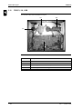
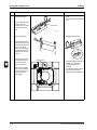
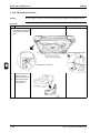
FUQ100, 125B
The illustration below shows the outlook and the dimensions of the unit (mm).
5
Part 1 – System Outline
ESIE05-04
Components
General Outline
1
The table below contains the different components of the unit.
No.
Component
1
Liquid pipe connection
2
Gas pipe connection
3
Drain pipe connection
4
Air outlet
5
Air suction grille
6
Corner decoration cover
7
Right pipe and wiring connection
8
Rear pipe and wiring connection
9
Cover for upwards pipe and wiring connection
10
Accessory drain elbow
3
4
5
Part 1 – System Outline
1–35
1–36
2. In case of using wireless
remote controller, this
position will be a signal
receiver. Refer to the drawing
of wireless remote controller
for detail.
hole
Mounting Location
5
Approx.
Approx.
Approx.
Name plate (Note 2)
50 OR MORE
(Required space)
2500 OR MORE
For installation in
50 or more
(Required space) high spaces
hole
(Piping and
Wiring intake)
Piping
direction
4
Outside line
Piping
direction
3
50 or more
(Required space)
Dimensions for
full open front
panel.
120 or less
Outlook and
dimensions
NOTES
1. Location of unit’s Name
Plate: Right side surface of
casing
Approx.
1.18
30 or more
(Required space)
11
Piping direction
General Outline
ESIE05-04
FAQ71B
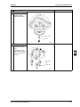
The illustration below shows the outlook and the dimensions of the unit (mm).
Part 1 – System Outline
ESIE05-04
Components
General Outline
1
The table below contains the different components of the unit.
No.
Component
1
Front panel
2
Front grille
3
Air outlet
4
Gas pipe
5
Liquid pipe
6
Drain hose
7
Grounding terminal
8
Right side pipe connection hole
9
Left side pipe connection hole
3
4
5
Part 1 – System Outline
1–37
or more
1–38
Detail A
(Mounting hole for installation plate)
Hole (For wood bolt)
Mounting Location
Approx.
Approx.
Approx.
5
Hole (For wood screw)
Ceiling surface
Oval hole (For wood screw)
Oval hole (For wood screw)
4
Brand name plate
(Note 2)
50 or more
(Required space)
hole
(Piping and
Wiring intake)
or more
(Service space
for air filter)
2. In case of using wireless remote
controller, this position will be a
signal receiver. Refer to the
drawing of wireless remote
controller for detail.
NOTES:
1. Location general rated name plate
Right side plate outside surface
Direction for air
filter draw out
3
or more
Outlook and
dimensions
(Required space)
11
1.19
(Required space)
Piping direction
General Outline
ESIE05-04
FAQ100B
The illustration below shows the outlook and the dimensions of the unit (mm).
Part 1 – System Outline
ESIE05-04
Components
General Outline
1
The table below contains the different components of the unit.
No.
Component
1
Front grille
2
Air filter
3
Discharge outlet
4
Gas piping connection
5
Gas piping connection
6
Drain piping connection
7
Earth terminal
8
Slit hole for right side piping connection
9
Slit hole for left side piping connection
3
4
5
Part 1 – System Outline
1–39
1–40
668 (Suspension position)
2. For maintenance of the air filter, it is necessary to provide a service
access panel according to the installation method. (Refer to the
‘Filter installation method’ drawing).
1. Refer to ‘Outlook drawing for installing optional accessories’ when
installing optional accessories.
NOTES:
300 or more
(Service space)
B
Suspension Bolt
Outlook and
dimensions
VIEW A
VIEW B
1.20
300 or more
(Installation space)
11
960 (Suspension
General Outline
ESIE05-04
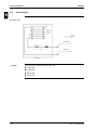
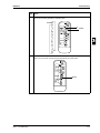
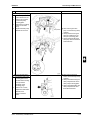
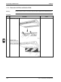
FDEQ71, 100B
The illustration below shows the outlook and the dimensions of the unit (mm).
3
4
5
Part 1 – System Outline
ESIE05-04
Components
General Outline
1
The table below contains the different components of the unit.
No.
Component
1
Liquid pipe connection
2
Gas pipe connection
3
Remote controller wiring connection
4
Power supply connection
5
Drain pipe connection
6
Air filter
7
Air suction side
8
Air discharge side
9
Nameplate
3
4
5
Part 1 – System Outline
1–41
4
1–42
2. For maintenance of the air filter, it is necessary to provide a
service access panel according to the installation method.
(Refer to the ‘Filter installation method’ drawing).
1. Refer to ‘Outlook drawing for installing optional accessories’
when installing optional accessories.
NOTES:
3
VIEW B
(Service space)
5
B
Suspension Bolt
Outlook and
dimensions
VIEW A
1.21
300 or more
(Installation space)
668 (Suspension position)
11
1360 (Suspension position)
General Outline
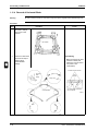
ESIE05-04
FDEQ125B
The illustration below shows the outlook and the dimensions of the unit (mm).
Part 1 – System Outline
ESIE05-04
Components
General Outline
1
The table below contains the different components of the unit.
No.
Component
1
Liquid pipe connection
2
Gas pipe connection
3
Remote controller wiring connection
4
Power supply connection
5
Drain pipe connection
6
Air filter
7
Air suction side
8
Air discharge side
9
Nameplate
3
4
5
Part 1 – System Outline
1–43
General Outline
ESIE05-04
11
3
4
5
1–44
Part 1 – System Outline
ESIE05-04
Specifications
Part 1
1
2
Specifications
2.1
What Is in This Chapter?
Introduction
Indoor units
Part 1 – System Outline
This chapter contains the following information:
Q
Technical specifications
Q
Electrical specifications
3
This chapter contains the following specifications:
Specifications
See page
2.2–FCQ – B
1–46
2.3–FCQ – D
1–47
2.4–FFQ – B
1–48
2.5–FBQ – B
1–49
2.6–FDQ – B
1–50
2.7–FHQ – B
1–51
2.8–FUQ – B
1–52
2.9–FAQ – B
1–53
2.10–FDEQ – B
1–54
4
5
1–45
Specifications
11
2.2
ESIE05-04
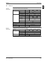
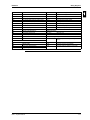
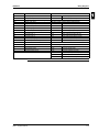
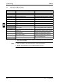
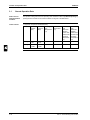
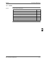
FCQ – B
Technical
specifications
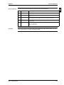
The table below contains the technical specifications.
Specification
Heat exchanger
FCQ35B7V1
FCQ50B7V1
Rows x stages x fin pitch
FCQ60B7V1
0.497 m²
HIXA diam. 7
HiXSS diam. 7
Fin type
Rhombus
Air flow rate cooling (high)
14 m³/min
15 m³/min
18 m³/min
18 m³/min
28 m³/min
31 m³/min
Air flow rate cooling (low)
10 m³/min
11 m³/min
14 m³/min
14 m³/min
21 m³/min
24 m³/min
Air flow rate heating (high)
14 m³/min
15 m³/min
18 m³/min
18 m³/min
28 m³/min
31 m³/min
Air flow rate heating (low)
10 m³/min
11 m³/min
14 m³/min
14 m³/min
21 m³/min
24 m³/min
Qty x model (rotor)
1 x QTS46B14M
Qty x model (motor)
1 x 19NFB6079
Fan speed
1 x QTS46A17M
1 x 19NFB6078
2 steps (direct drive)
Fan type
Refrigerant
FCQ125B7V3B
2 x 12 x 1.5 mm
0.331 m²
Tube type
3
FCQ100B7V3B
2 x 8 x 1.5 mm
Face area
Fan
FCQ71B7V3B
Turbo fan
Type
R410A
Safety and functional devices
Inline fuse (250V 5A)
4
Fan motor thermal protector
OFF: 130 +/- 5 °C
ON: 83 +/- 20 °C
OFF: 140 +/- 5 °C
ON: 45 +/- 15 °C
Drain pump thermal fuse
Air filter
Resin net (with mold resistant) - in decoration panel
Temperature control
Weight
5
Electrical
specifications
Computerized control
Unit
27.0 kg
The table below contains the electrical specifications.
Specification
Unit
Microprocessor thermostat for cooling and heating
23 kg
FCQ35B7V1
FCQ50B7V1
FCQ60B7V1
Phase
FCQ71B7V3B
Voltage
230V
Frequency
50 Hz
Power consumption
FCQ100B7V3B
FCQ125B7V3B
1~
140 W
161 W
_
Nominal running current
Fan motor
1–46
FLA (Full Load Amps)
0.6 A
1.0 A
No. of motors x output
1 x 45 W
1 x 90 W
Part 1 – System Outline
ESIE05-04
2.3
Specifications
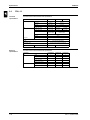
FCQ – D
Technical
specifications
1
The table below contains the technical specifications.
Specification
Heat exchanger
FCQ71DV3B
Rows x stages x fin pitch
Face area
FCQ100DV3B
FCQ140DV3B
2 x 12 x 1.2 mm
0.454 m²
0.544 m²
Tube type
Hi-XSS
Fin type
Fan
FCQ125DV3B
2 x 10 x 1.2 mm
Multi louver fin
Air flow rate cooling (high)
19 m³/min
Air flow rate cooling (low)
14 m³/min
30 m³/min
21 m³/min
24 m³/min
25 m³/min
Air flow rate heating (high)
Air flow rate heating (low)
Qty x model (rotor)
1 x QTS46F15M
1 x QTS46E17M
Qty x model (motor)
1x
EHDS50B30DK
(inverter)
1x
EHDS10B120DK
(inverter)
Fan speed
2
Fan type
Refrigerant
Turbo fan
Type
R410A
Safety and functional devices
_
Air filter
Electrical
specifications
Microcomputer control
Unit
24 kg
28 kg
The table below contains the electrical specifications.
Specification
Unit
FCQ71DV3B
Phase
FCQ100DV3B
FCQ125DV3B
FCQ140DV3B
1~
Voltage
230V
Frequency
50 Hz
Nominal running current
Fan motor
Part 1 – System Outline
4
Resin net (with mold resistant) - in decoration panel
Temperature control
Weight
3
_
FLA (Full Load Amps)
0.30 A
0.70 A
No. of motors x output
1 x 30 W
1 x 120 W
1–47
5
Specifications
11
2.4
ESIE05-04
FFQ – B
Technical
specifications
The table below contains the technical specifications.
Specification
Heat exchanger
FFQ25B7V1B
FFQ35B7V1B
Rows x stages x fin pitch
Face area
0.269 m²
Tube type
HiXSS diam. 7
Fin type
Fan
3
Multi louver fin
9.0 m³/min
10.0 m³/min
12.0 m³/min
15.0 m³/min
Air flow rate cooling (low)
6.5 m³/min
6.5 m³/min
8.0 m³/min
10.0 m³/min
Air flow rate heating (high)
9.0 m³/min
10.0 m³/min
–
15.0 m³/min
Air flow rate heating (low)
6.5 m³/min
6.5 m³/min
–
10.0 m³/min
Qty x model (rotor)
1 x QTS32C15M
Qty x model (motor)
1 x D16P52A23
2 steps
Fan type
Turbo fan
Type
R410A
Safety and functional devices
Inline fuse (250V 5A)
Fan motor thermal protector
4
Air filter
5
Electrical
specifications
Microcomputer control
Unit
17.5 kg
The table below contains the electrical specifications.
Specification
Unit
Fan motor
FFQ25B7V1B
FFQ35B7V1B
Phase
FFQ50B7V1B
FFQ60B7V1B
1~
Voltage
230V
Frequency
50 Hz
Power consumption
73 W
84 W
97 W
120 W
Nominal running current
0.37 A
0.40 A
0.49 A
0.61 A
FLA (Full Load Amps)
No. of motors x output
1–48
OFF: 130 +/- 5 °C
ON: 83 +/- 20 °C
Removable/washable/mildew proof/long life (in decoration panel)
Temperature control
Weight
FFQ60B7V1B
Air flow rate cooling (high)
Fan speed
Refrigerant
FFQ50B7V1B
2x10x1.5 mm
0.60 A
0.70 A
1 x 55 W
Part 1 – System Outline
ESIE05-04
2.5
Specifications
FBQ – B
Technical
specifications
1
The table below contains the technical specifications.
Specification
Heat exchanger
FBQ35B7V1
FBQ50B7V1
FBQ60B7V1
Rows x stages x fin pitch
0.132 m²
Tube type
0.221 m²
FBQ125B7V3B
0.338 m²
HI-XA diam. 7
Hi-XSS diam. 7
Fin type
Rhombus
Air flow rate cooling (high)
11.5 m³/min
14.0 m³/min
19.0 m³/min
19.0 m³/min
27.0 m³/min
Air flow rate cooling (low)
9.0 m³/min
10.0 m³/min
14.0 m³/min
14.0 m³/min
20.0 m³/min
24.0 m³/min
Air flow rate heating (high)
11.5 m³/min
14.0 m³/min
19.0 m³/min
19.0 m³/min
27.0 m³/min
35.0 m³/min
Air flow rate heating (low)
9.0 m³/min
10.0 m³/min
14.0 m³/min
14.0 m³/min
20.0 m³/min
24.0 m³/min
Qty x model (rotor)
Qty x model (motor)
1 x QD18G3BM
1 x CA-0513D
Fan speed
1 x CA-0514D
35.0 m³/min
2 x QD18G2BM
3 x QD18G2BM
1 x CA-0515SEK
1 x A37P135G20
2 steps (direct drive)
Sirocco
Type
R410A
Safety and functional devices
Inline fuse (250V 5A)
_
4
Fan motor thermal fuse 152 +/-2 °C
Air filter
Resin net (with mold resistant)
Temperature control
Weight
Computerized control
Unit
Electrical
specifications
30 kg
Fan motor
31 kg
Microprocessor thermostat for cooling and heating
41 kg
41 kg
51 kg
52 kg
FBQ71B7V3B
FBQ100B7V3B
FBQ125B7V3B
The table below contains the electrical specifications.
Specification
Unit
FBQ35B7V1
FBQ50B7V1
5
FBQ60B7V1
Phase
1~
Voltage
230 V
Frequency
50Hz
Power consumption
_
Nominal running current
_
FLA (Full Load Amps)
0.5 A
0.7 A
No. of motors x output
1 x 65 W
1 x 85 W
Part 1 – System Outline
3
3 steps (direct drive)
Fan type
Refrigerant
FBQ100B7V3B
3 x 14 x 1.75 mm
Face area
Fan
FBQ71B7V3B
0.9 A
1 x 125 W
1.0 A
1 x 125 W
1 x 135 W
1 x 225 W
1–49
Specifications
11
2.6
ESIE05-04
FDQ – B
Technical
specifications
The table below contains the technical specifications.
Specification
Heat exchanger
FDQ125B7V3B
Rows x stages x fin pitch
0.338 m²
0.634 m²
Tube type
Hi-XSS diam. 7
Hi-XSS (8)
Rhombus
43.0 m³/min
69 m³/min
89 m³/min
Air flow rate heating
43.0 m³/min
69 m³/min
89 m³/min
1x
DPA216-178NB
Fan speed
Sirocco
Type
R410A
Safety and functional devices
Fan motor thermal fuse: 160 °C
Air filter
Resin net (with mold resistant)
Temperature control
Weight
1x
DPC241-241NB
1 step (direct drive)
Fan type
Refrigerant
Non-symmetric fin
Air flow rate cooling
Qty x model (rotor + motor)
3
FDQ250B7V3B
3 x 24 x 2.00 mm
Face area
Fin type
Fan
FDQ200B7V3B
3 x 14 x 1.75 mm
Microprocessor thermostat for cooling and
heating
Unit
59.0 kg
93 Kg
4
Electrical
specifications
The table below contains the electrical specifications.
Specification
Unit
5
Fan motor
1–50
FDQ125B7V3B
FDQ200B7V3B
FDQ250B7V3B
Phase
1~
1~
1~
Voltage
230 V
230 V
230 V
Frequency
50Hz
50Hz
50Hz
Power consumption
_
_
_
Nominal running current
_
_
_
FLA (Full Load Amps)
4.2 A
6.8 A
7.6 A
No. of motors x output
1 x 500 W
1 x 650 W
1 x 1000 W
Part 1 – System Outline
ESIE05-04
2.7
Specifications
FHQ – B
Technical
specifications
1
The table below contains the technical specifications.
Specification
Heat exchanger
Rows x stages x fin pitch
FHQ35BUV1B
FHQ50BUV1B
FHQ60BUV1B
2 x 12 x 1.75 mm
3 x 12 x 1.75 mm
2 x 12 x 1.75 mm
Face area
0.182 m²
FHQ125BUV1B
0.293 m²
0.341 m²
N-Hix
Fin type
Multi louver
Air flow rate cooling (high)
13.0 m³/min
17.0 m³/min
17.0 m³/min
24.0 m³/min
30.0 m³/min
Air flow rate cooling (low)
10.0 m³/min
13.0 m³/min
14.0 m³/min
20.0 m³/min
25.0 m³/min
Air flow rate heating (high)
13.0 m³/min
16.0 m³/min
17.0 m³/min
24.0 m³/min
30.0 m³/min
Air flow rate heating (low)
10.0 m³/min
13.0 m³/min
14.0 m³/min
20.0 m³/min
25.0 m³/min
Qty x model (rotor)
2 x QD12K1AH
1 x QD12K1BH
3 x QD12K1AH
1 x QD12K1BH
Qty x model (motor)
Refrigerant
FHQ100BUV1B
3 x 12 x 1.75 mm
0.233 m²
Tube type
Fan
FHQ71BUV1B
3 x QD12K2AH
1 x QD12K2BH
D09P62A20
D10P130H23
Fan speed
2 steps
Fan type
Sirocco
Type
R410A
Safety and functional devices
Fuse (250V 5A)
–
4
OFF: 130 +/- 5 °C
Fan motor thermal protector
ON: 83 +/- 20 °C
Air filter
Removable/washable
Temperature control
Microcomputer control
Weight
Unit
Electrical
specifications
24 kg
25 kg
27 kg
35 kg
5
FHQ35BUV1B
FHQ50BUV1B
FHQ60BUV1B
FHQ71BUV1B
Phase
1~
Voltage
230 V
Frequency
Nominal running current
FLA (Full load amps)
No. of motors x output
Part 1 – System Outline
FHQ100BUV1B
FHQ125BUV1B
135 W
144 W
50Hz
Power consumption
Fan motor
32 kg
The table below contains the electrical specifications.
Specification
Unit
3
111 W
0.45 A
115 W
0.52 A
117 W
–
0.6 A
0.7 A
1 x 62 W
1 x 130 W
1–51
Specifications
11
2.8
ESIE05-04
FUQ – B
Technical
specifications
The table below contains the technical specifications.
Specification
Heat exchanger
FUQ71BUV1B
Rows x stages x fin pitch
Face area
0.353 m²
N-Hix
Fin type
Multi louver
Air flow rate cooling (high)
19.0 m³/min
29.0 m³/min
Air flow rate cooling (low)
14.0 m³/min
21.0 m³/min
23.0 m³/min
Air flow rate heating (high)
19.0 m³/min
29.0 m³/min
32.0 m³/min
14.0 m³/min
21.0 m³/min
23.0 m³/min
Air flow rate heating (low)
3
Qty x model (rotor)
1 x QTS48A10M
Qty x model (motor)
1 x D16P45R23
Fan speed
4
Fan motor thermal protector:
5
Microcomputer control
Unit
25 kg
31 kg
The table below contains the electrical specifications.
Specification
Unit
FUQ71BUV1B
1~
Voltage
220-240 V
Power consumption
FUQ125BUV1B
50 Hz
180 W
Nominal running current
Fan motor
FUQ100BUV1B
Phase
Frequency
1–52
ON: 130 +/- 5 °C
OFF: 83 +/- 20 °C
Resin net (with mold resistant)
Temperature control
Electrical
specifications
1 x D17P90J23
R410A
Air filter
Weight
1 x QTS50B15M
Turbo fan
Type
Safety and functional devices
32.0 m³/min
2 steps
Fan type
Refrigerant
FUQ125BUV1B
3 x 8 x 1.5 mm
0.265 m²
Tube type
Fan
FUQ100BUV1B
3 x 6 x 1.5 mm
289 W
_
FLA (Full load amps)
0.6 A
1.0 A
No. of motors x output
1 x 45 W
1 x 90 W
Part 1 – System Outline
ESIE05-04
2.9
Specifications
FAQ – B
Technical
specifications
1
The table below contains the technical specifications.
Specification
Heat exchanger
FAQ71BUV1B
FAQ100BUV1B
2 x 16 x 1.4 mm
2 x 12 x 1.4 mm
Face area
0.289 m²
0.332 m²
Tube type
Hi-XA
Rows x stages x fin pitch
Fin type
Fan
N-Hix
Multi louver
Air flow rate cooling (high)
19.0 m³/min
23.0 m³/min
Air flow rate cooling (low)
15.0 m³/min
19.0 m³/min
Air flow rate heating (high)
19.0 m³/min
23.0 m³/min
Air flow rate heating (low)
15.0 m³/min
19.0 m³/min
Qty x model (rotor)
1 x QCL9886M
1 x QCL1163MA +
1 x QCL1163MB
Qty x model (motor)
1x
(ARW30R8P43DA)
1 x D09P49A23
Fan speed
2 steps
Fan type
Refrigerant
Microcomputer control
Unit
13 kg
26 kg
The table below contains the electrical specifications.
Specification
Unit
FAQ71BUV1B
1~
Voltage
220-240 V
Power consumption
50 Hz
68 W
Nominal running current
Fan motor
101 W
_
FLA (Full load amps)
No. of motors x output
5
FAQ100BUV1B
Phase
Frequency
Part 1 – System Outline
4
Resin net (mildew proof)
Temperature control
Electrical
specifications
R410A
Fan motor thermal OFF: 130 +/- 5 °C
protector: ON: 83 +/- 20 °C
Air filter
Weight
Cross flow fan
Type
Safety and functional devices
3
0.4 A
1 x 43 W
1 x 49 W
1–53
Specifications
11
2.10
ESIE05-04
FDEQ – B
Technical
specifications
The table below contains the technical specifications.
Specification
Heat exchanger
FDEQ71B7V3B
Rows x stages x fin pitch
FDEQ100B7V3B
Face area
0.226 m²
Tube type
Rhombus
Air flow rate cooling (high)
16.0 m³/min
24.0 m³/min
Air flow rate cooling (low)
12.0 m³/min
17.0 m³/min
20.0 m³/min
Air flow rate heating (high)
19.0 m³/min
28.0 m³/min
35.0 m³/min
Air flow rate heating (low)
14.0 m³/min
20.0 m³/min
Qty x model (rotor)
3
Qty x model (motor)
MLA6027
MLA6028
Fan type
4
R410A
Fan motor thermal fuse: 152 +/-2 °C
Resin net (with mold resistant)
Temperature control
Electrical
specifications
5
Computerized control
Unit
38.1 kg
48.6 kg
The table below contains the electrical specifications.
Specification
Unit
FDEQ71B7V3B
1~
Voltage
230 V
Power consumption
195 W
415 W
_
FLA (Full load amps)
No. of motors x output
FDEQ125B7V3B
50 Hz
150 W
Nominal running current
Fan motor
FDEQ100B7V3B
Phase
Frequency
1–54
A37P225E23
Sirocco
Air filter
Weight
24.0 m³/min
2 steps, direct drive
Type
Safety and functional devices
30.0 m³/min
2 x QD18G2AM
1 x QD18G2BM
2 x QD18G3BM
Fan speed
Refrigerant
0.344 m²
Hi-XSS diam. 7
Fin type
Fan
FDEQ125B7V3B
3 x 14 x 1.75 mm
_
1 x 130 W
1 x 155 W
1 x 225 W
Part 1 – System Outline
ESIE05-04
Functional Diagrams
Part 1
1
3
Functional Diagrams
3.1
What Is in This Chapter?
Introduction
Functional
diagrams
This chapter contains the following information:
Q
Functional diagrams
Q
Pipe connection diameters.
3
This chapter contains the following functional diagrams:
Functional diagram
See page
3.2–Indoor Piping
1–56
3.3–Pipe Connection Diameters
1–58
3.4–Piping Components
1–59
4
5
Part 1 – System Outline
1–55
Functional Diagrams
11
3.2
ESIE05-04
Indoor Piping
All indoor units
2
R3T (*)
4
R1T
Heating
Cooling
R2T
3
Liquid piping
3
1a
Gas piping
4
1a
Indoor unit
5
(*) Remark
1–56
R3T only present on following types of indoor units:
Q
FCQ35~60B
Q
FFQ25~60B
Q
FBQ35~60B
Q
FHQ35~60B
Part 1 – System Outline
ESIE05-04
Piping components
(*) Remark
Functional Diagrams
1
The table below contains the different components of the functional diagrams.
No.
Component
Function / remark
1a
Flare connection
See pipe connection diameter.
2
Heat exchanger
The heat exchanger is of the multi louvre fin type. Hi-X -tubes and coated waffle louvre fins are
used.
3
Filter
The filter is used to collect impurities, which may enter the system during installation and is also
used to avoid blockage of the capillaries and other fine mechanical parts of the unit.
4
Fan
Depending on indoor unit type, an axial or centrifugal fan is used. See chapter on specifications
for the exact type.
5
Thermistor
Q
R1T: Air thermistor
Q
R2T: Liquid thermistor
Q
R3T: Coil thermistor (*)
3
Sensor R3T on indoor coil of FCQ35~60B, FFQ35~60B, FBQ35~60B & FHQ35~60BU is not used
when connected to sky-air outdoor units (RR, RQ, RZQ).
4
5
Part 1 – System Outline
1–57
Functional Diagrams
11
3.3
ESIE05-04
Pipe Connection Diameters
Indoor units
The table below contains the refrigerant pipe connection diameters.
∅ Gas pipe (flare)
∅ Liquid pipe (flare)
FCQ35B
9.5 mm
6.4 mm
FCQ50, 60B
12.7 mm
6.4 mm
FCQ71, 100, 125B
15.9 mm
9.5 mm
FCQ71, 100, 125D
15.9 mm
9.5 mm
FFQ25, 35B
9.5 mm
6.4 mm
FFQ50, 60B
12.7 mm
6.4 mm
FBQ35B
9.5 mm
6.4 mm
FBQ50, 60B
12.7 mm
6.4 mm
FBQ71, 100, 125B
15.9 mm
9.5 mm
FDQ125B
15.9 mm
9.5 mm
FDQ200B
28.6 mm
12.7 mm
FDQ250B
28.6 mm
15.9 mm
FHQ35B
9.5 mm
6.4 mm
FHQ50, 60B
12.7 mm
6.4 mm
FHQ71, 100, 125B
15.9 mm
9.5 mm
FUQ71, 100, 125B
15.9 mm
9.5 mm
FAQ71, 100B
15.9 mm
9.5 mm
FDEQ71, 100, 125B
15.9 mm
9.5 mm
Model
3
4
5
1–58
Part 1 – System Outline
Part 1 – System Outline
ESIE05-04
Component
Flare connection
Heat exchanger
Filter
Fan
Thermistor
No.
1a
2
3
4
5
Part 1
R3T: Discharge pipe thermistor
R2T: Coil thermistor
R1T: Air thermistor
1–59
The filter is used to collect impurities, which may enter the system during installation and is also
used to avoid blockage of the capillaries and other fine mechanical parts of the unit.
The heat exchanger is of the multi louvre fin type. Hi-X -tubes and coated waffle louvre fins are
used.
See pipe connection diameter.
Function / remark
The table below contains the different components of the functional diagrams.
Piping Components
Components
3.4
1–60
Part 1 – System Outline
ESIE05-04
ESIE05-04
Wiring Diagrams
Part 1
1
4
Wiring Diagrams
4.1
What Is in This Chapter?
Introduction
This chapter contains the wiring diagrams of the indoor units.
Indoor units:
This chapter contains the following wiring diagrams:
Part 1 – System Outline
3
Wiring diagram
See page
4.2–FCQ35, 50, 60B
1–62
4.3–FCQ71, 100, 125B
1–64
4.4–FCQ71, 100, 125, 140D
1–66
4.5–FFQ25, 35, 50, 60B
1–68
4.6–FBQ35, 50, 60B
1–70
4.7–FBQ71B
1–72
4.8–FBQ100, 125B
1–74
4.9–FDQ125, 200, 250B
1–76
4.10–FHQ35, 50, 60B
1–78
4.11–FHQ71, 100, 125B
1–80
4.12–FUQ71, 100, 125B
1–82
4.13–FAQ71B
1–84
4.14–FAQ100B
1–86
4.15–FDEQ71B
1–88
4.16–FDEQ100B
1–90
4.17–FDEQ125B
1–92
4
5
1–61
Wiring Diagrams
11
4.2
ESIE05-04
FCQ35, 50, 60B
Wiring diagram
The illustration below shows the wiring diagram of the unit.
indoor
Wired remote
controller
outdoor
Norm.emerg.
Note 3
Receiver / Display unit
3
Terminals for Operation
Indicator
Fan Operation
Compressor Operation
Remote
controller
(Slave)
4
(Master)
Outdoor
unit
Simultaneous Operation System
: Field wiring
: Connector
: Wire lamp
: Protective earth (screw)
: Terminal
5
Adaptor for
wiring
Colors:
BLK : Black
RED : Red
WHT : White
YLW : Yellow
Switch box
Notes:
1. Use copper conductors only.
2. When using the central remote controller, see manual for connection
to the unit.
3. X24A is connected when the wireless remote controller kit is used.
4. The remote controller model varies according to the combination
system. See technical data and catalogs before connecting.
1–62
Part 1 – System Outline
ESIE05-04
Wiring Diagrams
33H
Float switch
Wired remote controller
A1P
Printed circuit board
SS1
C1R
Capacitor (M2F)
1
Selector switch (Main/Sub)
F1U
Fuse (5A, 250V)
Receiver/display unit (attached to wireless remote controller)
HAP
Light emitting diode (Service monitor-green)
A2P, A3P
M1A
Motor (Swing flap)
BS
ON/OFF button
M2F
Motor (Indoor fan)
H1P
Light emitting diode (on-red)
M3P
Motor (Drain pump)
H2P
Light emitting diode (timer-green)
Q1F
Thermo switch (M2F embedded)
H3P
Light emitting diode (filter sign-red)
R1T
Thermistor (Air)
H4P
Light emitting diode (defrost-orange)
R2T
Thermistor (Liquid)
SS1
Selector switch (Main/Sub)
R3T
Thermistor (Coil)
SS2
Selector switch (Wireless address set)
RyP
Magnetic relay (M3P)
SS1
Selector switch (Emergency)
Adaptor for wiring
T1R
Transformer (220V~240V/22 V)
RyC, RyF
Printed circuit board
3
Magnetic relay
X1M
Terminal strip (Power)
X2M
Terminal strip (Control)
Connector for optional parts
PC
Phase control circuit
X60A, X61A
Connector (Interface adaptor for Sky Air series)
RC
Signal receiver circuit
X33A
Connector (Adaptor for wiring)
TC
Signal transmission circuit
X35A
Connector (Group control adaptor)
X40A
Connector (Remote ON/OFF, Forced OFF)
4
5
Part 1 – System Outline
1–63
Wiring Diagrams
11
4.3
ESIE05-04
FCQ71, 100, 125B
Wiring diagram
The illustration below shows the wiring diagram of the unit.
indoor
Wired Remote
Controller
outdoor
Norm.emerg.
Note 3
Receiver / Display unit
3
Terminals for Operation
Indicator
Fan Operation
Compressor Operation
Remote
controller
: Field wiring
: Connector
: Wire lamp
: Protective earth (screw)
: Terminal
5
(Slave)
4
(Master)
Outdoor
unit
Simultaneous Operation System
Remote
ON/OFF
Forced OFF
Adaptor for
wiring
Colors:
BLK : Black
RED : Red
WHT : White
YLW : Yellow
Switch box
Notes:
1. Use copper conductors only.
2. When using the central remote controller, see manual for connection
to the unit.
3. X24A is connected when the wireless remote controller kit is used.
4. The remote controller model varies according to the combination
system. See technical data and catalogs before connecting.
1–64
Part 1 – System Outline
ESIE05-04
Wiring Diagrams
S1L
Float switch
Receiver/display unit (attached to wireless remote controller)
A1P
Printed circuit board
A2P, A3P
Printed circuit board
C1R
Capacitor (M2F)
BS
ON/OFF button
HAP
Light emitting diode (Service monitor-green)
H1P
Light emitting diode (on-red)
M1A
Motor (Swing flap)
H2P
Light emitting diode (timer-green)
M2F
Motor (Indoor fan)
H3P
Light emitting diode (filter sign-red)
M3P
Motor (Drain pump)
H4P
Light emitting diode (defrost-orange)
Q1F
Thermo switch (M2F embedded)
SS1
Selector switch (Main/Sub)
R1T
Thermistor (Air)
SS2
Selector switch (Wireless address set)
R2T
Thermistor (Liquid)
RyP
Magnetic relay (M3P)
Adaptor for wiring
SS1
Selector switch (Emergency)
RyC, RyF
T1R
Transformer (220V~240V/22 V)
X1M
Terminal strip (Power)
Connector for optional parts
X2M
Terminal strip (Control)
X60A, X61A
Connector (Interface adaptor for Sky Air series)
PC
Phase control circuit
X33A
Connector (Adaptor for wiring)
RC
Signal receiver circuit
X35A
Connector (Group control adaptor)
TC
Signal transmission circuit
X40A
Connector (Remote ON/OFF, Forced OFF)
Magnetic relay
3
4
Wired remote controller
SS1
1
Selector switch (Main/Sub)
5
Part 1 – System Outline
1–65
Wiring Diagrams
11
4.4
ESIE05-04
FCQ71, 100, 125, 140D
Wiring diagram
The illustration below shows the wiring diagram of the unit.
Receiver / Display Unit
to Outdoor
Unit
Norm.Emg.
Note 5
Note 5
Note 2
Central
Remote
Controller
3
Wired Remote
Controller
to Outdoor Unit
In case of simultaneous
operation system
Indoor unit
Indoor unit
(Slave)
(Master)
4
Remote Controller
Switch box
(Indoor Unit)
Notes
1.
5
: Terminal
: Connector
: Field wiring
2. In case using central remote controller, connect it to the unit in accordance with
the attached installation manual.
3. Remote controller model varies according to the combination system, confirm
engineering materials and catalogs, etc. before connecting.
4. Confirm the method of setting the selector switch (SS1, SS2) by installation
manual and engineering data, etc.
5. Ground the shield of the remote controller cord to the indoor unit (in case of
using shield wire).
6. Symbols show as follows:
RED : Red
BLK : Black
WHT : White
YLW : Yellow
GRN : Green
ORG : Orange
BRN : Brown
PNK : Pink
GRY : Gray
BLU : Blue
1–66
Part 1 – System Outline
ESIE05-04
Wiring Diagrams
A1P
Printed circuit board (Power supply)
Receiver/display unit (attached to wireless remote controller)
A2P
Printed circuit board (Control)
A4P
Printed circuit board
A3P
Printed circuit board (Humidity sensor unit)
A5P
Printed circuit board
HAP
Light emitting diode (Service monitor-green)
BS1
Push button (ON/OFF)
KPR
Magnetic relay (M1P)
H1P
Light emitting diode (on-red)
M1F
Motor (Indoor fan)
H2P
Light emitting diode (timer-green)
M1P
Motor (Drain pump)
H3P
Light emitting diode (filter sign-red)
M1S
Motor (Swing flap)
H4P
Light emitting diode (defrost-orange)
R1T
Thermistor (Air)
SS1
Selector switch (Main/Sub)
R2T
Thermistor (Coil)
SS2
Selector switch (Wireless address set)
S1L
Float switch
SS1
Selector switch (Emergency)
Wired remote controller
X1M
Terminal strip
R1T
Thermistor (Air)
X2M
Terminal strip
SS1
Selector switch (Main/Sub)
Z1C
Noise filter
Z2C
Noise filter
Connector for optional parts
PC
Power circuit
X33A
Connector (Adaptor for wiring)
RC
Signal receiver circuit
X35A
Connector (Control adaptor)
TC
Signal transmission circuit
1
3
4
5
Part 1 – System Outline
1–67
Wiring Diagrams
11
4.5
ESIE05-04
FFQ25, 35, 50, 60B
Wiring diagram
The illustration below shows the wiring diagram of the unit.
to Outdoor Unit
In case of simultaneous operation system
Indoor unit Indoor unit
(Master) (Slave)
to Outdoor Unit
: Connector discrimination colour for components.
: Connector colour for components.
: Connector colour for printed circuit board.
Remote
Controller
3
Note 3
4
Note 5
Wired Remote
Controller
Note 3
Receiver / Display unit
Notes
5
1.
: Terminal
: Connector
: Field wiring
2. In case using central remote controller, connect it to the unit in accordance with
the attached installation manual.
3. X24A is connected when the wireless remote controller kit is being used.
4. Remote controller model varies according to the combination system, confirm
engineering materials and catalogs, etc. before connecting.
5. Ground the shield of the remote controller cord to the indoor unit (in case of
using shield wire).
6. Symbols show as follows:
BLK : Black
WHT : White
YLW : Yellow
PRP : Purple
GRY : Gray
BLU : Blue
1–68
Control box
Part 1 – System Outline
ESIE05-04
Wiring Diagrams
A1P
Printed circuit board
Wired remote controller
C1
Capacitor (M1F)
R1T
Thermistor (Air)
F1U
Fuse (F5A, 250V)
SS1
Selector switch (Main/Sub)
HAP
Light emitting diode (Service monitor-green)
1
KPR
Magnetic relay (M1P)
Wireless remote controller (Receiver/display unit)
M1F
Motor (Indoor fan)
A3P
Printed circuit board
M1P
Motor (Drain pump)
A4P
Printed circuit board
M1S
Motor (Swing flap)
BS1
Push button (ON/OFF)
Q1M
Thermo switch (M1F embedded)
H1P
Light emitting diode (on-red)
R1T
Thermistor (Air)
H2P
Light emitting diode (timer-green)
R2T
Thermistor (Coil~1)
H3P
Light emitting diode (filter sign-red)
R3T
Thermistor (Coil~2)
H4P
Light emitting diode (defrost-orange)
S1L
Float switch
SS1
Selector switch (Main/Sub)
T1R
Transformer (220~240V/22 V)
SS2
Selector switch (Wireless address set)
V1TR
Phase control circuit
X1M
Terminal strip
Connector for optional parts
X2M
Terminal strip
X33A
RC
Signal receiver circuit
X35A
Connector (Group control adaptor)
TC
Signal transmission circuit
X40A
Connector (Remote ON/OFF, Forced OFF)
X60A, X61A
Connector (Interface adaptor for Sky Air series)
3
Connector (Adaptor for wiring)
4
5
Part 1 – System Outline
1–69
Wiring Diagrams
11
4.6
ESIE05-04
FBQ35, 50, 60B
Wiring diagram
The illustration below shows the wiring diagram of the unit.
35,50,60,CLASS
outdoor
indoor
Wired Remote
Controller
3
Details of Wired
Remote Controller
(Optional accessory)
5
Compressor
Operation
4
Fan
Operation
Terminals for
Operation Indicator
Adaptor for wiring
Switch box
Notes:
1. When using the central remote controller, see manual for connection
to the unit.
2. The remote controller model varies according to the combination
system. See technical materials and catalogues, etc. before
connecting.
1–70
: Field wiring
: Terminal
: Connector
: Wire lamp
: Protective earth (screw)
Colors:
BLK : Black
BLU : Blue
GRY : Gray
ORG : Orange
RED : Red
WHT : White
Part 1 – System Outline
ESIE05-04
Wiring Diagrams
33H
Float switch
Wired remote controller
A1P
Printed circuit board
BS1
ON/OFF button
C1R
Capacitor (Fan)
BS2
Timer mode start/stop button
F1U
Fuse (5A, 250V)
BS3, BS8
Programming time button
F1T
Thermal fuse (152°C) (M1F embedded)
BS4, BS9
Temperature setting button
HAP
Light emitting diode (Service monitor-green)
BS6
Operation mode selector button
M1F
Motor (Fan)
BS7
Timer ON/OFF button
M1P
Motor (Drain pump)
BS11
Fan speed control button
R1T
Thermistor (Air)
BS12
Inspection/test operation button
R2T
Thermistor (Liquid)
BS14
Filter sign reset button
R3T
Thermistor (Coil)
H1P
Light emitting diode (Service monitor-red)
RyF1-4
Magnetic relay (Fan)
LCD
Liquid cristal display
RyP
Magnetic relay (Drain pump)
SS1
Selector switch (Main/sub)
1
3
SS1
Selector switch (Emergency)
T1R
Power supply transformer (220~240V/21.8V)
Connector for optional parts
X1M
Terminal strip
X60A, X61A
X2M
Terminal strip
Connector (Interface adaptor for Sky Air/US
series)
RC
Signal receiver circuit
X33A
Connector (Adaptor for wiring)
TC
Signal transmission circuit
X35A
Connector (Group control adaptor)
X40A
Connector (Remote ON/OFF, Forced OFF)
4
Adaptor for wiring
RyC, RyF
Magnetic relay
5
Part 1 – System Outline
1–71
Wiring Diagrams
11
4.7
ESIE05-04
FBQ71B
Wiring diagram
The illustration below shows the wiring diagram of the unit.
71 CLASS
outdoor
indoor
Wired Remote
Controller
3
Fan
Operation
Details of Wired
Remote Controller
(Optional accessory)
Remote
ON/OFF
Forced OFF
5
Compressor
Operation
Terminals for
Operation Indicator
4
Adaptor for wiring
Switch box
Notes:
1. When using the central remote controller, see manual for connection
to the unit.
2. The remote controller model varies according to the combination
system. See technical materials and catalogues, etc. before
connecting.
1–72
: Field wiring
: Terminal
: Connector
: Wire lamp
: Protective earth (screw)
Colors:
BLK : Black
BLU : Blue
GRY : Gray
ORG : Orange
RED : Red
WHT : White
Part 1 – System Outline
ESIE05-04
Wiring Diagrams
S1L
Float switch
Wired remote controller
A1P
Printed circuit board
BS1
ON/OFF button
C1R
Capacitor (Fan)
BS2
Timer mode start/stop button
F1T
Thermal fuse (152°C) (M1F embedded)
BS3, BS8
Programming time button
HAP
Light emitting diode (Service monitor-green)
BS4, BS9
Temperature setting button
M1F
Motor (Fan)
BS6
Operation mode selector button
M1P
Motor (Drain pump)
BS7
Timer ON/OFF button
R1T
Thermistor (Air)
BS11
Fan speed control button
R2T
Thermistor (Coil)
BS12
Inspection/test operation button
1
RyF1-4
Magnetic relay (Fan)
BS14
Filter sign reset button
RyP
Magnetic relay (Drain pump)
H1P
Light emitting diode (Service monitor-red)
SS1
Selector switch (Emergency)
LCD
Liquid cristal display
T1R
Power supply transformer (220~240V/21.8V)
SS1
Selector switch (Main/sub)
X1M
Terminal strip
X2M
Terminal strip
Connector for optional parts
RC
Signal receiver circuit
X60A, X61A
TC
Signal transmission circuit
Connector (Interface adaptor for Sky Air/US
series)
X33A
Connector (Adaptor for wiring)
Adaptor for wiring
RyC, RyF
Magnetic relay
X35A
Connector (Group control adaptor)
X40A
Connector (Remote ON/OFF, Forced OFF)
3
4
5
Part 1 – System Outline
1–73
Wiring Diagrams
11
4.8
ESIE05-04
FBQ100, 125B
Wiring diagram
The illustration below shows the wiring diagram of the unit.
100,125 CLASS
outdoor
indoor
Wired Remote
Controller
3
Fan
Operation
4
Details of Wired
Remote Controller
(Optional accessory)
Remote
ON/OFF
Forced OFF
5
Compressor
Operation
Terminals for
Operation Indicator
Adaptor for wiring
Switch box
Notes:
1. When using the central remote controller, see manual for connection
to the unit.
2. The remote controller model varies according to the combination
system. See technical materials and catalogues, etc. before
connecting.
1–74
: Field wiring
: Terminal
: Connector
: Wire lamp
: Protective earth (screw)
Colors:
BLK : Black
BLU : Blue
GRY : Gray
ORG : Orange
RED : Red
WHT : White
BRN : Brown
Part 1 – System Outline
ESIE05-04
Wiring Diagrams
S1L
Float switch
Wired remote controller
A1P
Printed circuit board
BS1
ON/OFF button
C1R
Capacitor (Fan)
BS2
Timer mode start/stop button
F1T
Thermal fuse (152°C) (M1F embedded)
BS3, BS8
Programming time button
HAP
Light emitting diode (Service monitor-green)
BS4, BS9
Temperature setting button
M1F
Motor (Fan)
BS6
Operation mode selector button
M1P
Motor (Drain pump)
BS7
Timer ON/OFF button
R1T
Thermistor (Air)
BS11
Fan speed control button
R2T
Thermistor (Coil)
BS12
Inspection/test operation button
1
RyF1-4
Magnetic relay (Fan)
BS14
Filter sign reset button
RyP
Magnetic relay (Drain pump)
H1P
Light emitting diode (Service monitor-red)
SS1
Selector switch (Emergency)
LCD
Liquid cristal display
T1R
Power supply transformer (220~240V/21.8V)
SS1
Selector switch (Main/sub)
X1M
Terminal strip
X2M
Terminal strip
Connector for optional parts
RC
Signal receiver circuit
X60A, X61A
TC
Signal transmission circuit
Connector (Interface adaptor for Sky Air/US
series)
X33A
Connector (Adaptor for wiring)
Adaptor for wiring
RyC, RyF
Magnetic relay
X35A
Connector (Group control adaptor)
X40A
Connector (Remote ON/OFF, Forced OFF)
3
4
5
Part 1 – System Outline
1–75
Wiring Diagrams
11
4.9
ESIE05-04
FDQ125, 200, 250B
Wiring diagram
The illustration below shows the wiring diagram of the unit.
125 CLASS
outdoor
Wired Remote
Controller
indoor
3
4
Details of Wired
Remote Controller
5
Switch box
Remote
ON/OFF
Forced OFF
Compressor
Operation
Fan
Operation
Terminals for
Operation Indicator
Adaptor for wiring
: Terminal
: Field wiring
1–76
Notes:
: Protective earth (screw)
1. When using the central remote controller, see manual for
connection to the unit.
2. Be sure that the power supply is switched off before
opening the switch box.
* L-TAP is not available for 250 Class.
: Connector
Colors:
BLK : Black
BLU : Blue
RED : Red
WHT : White
YLW : Yellow
Part 1 – System Outline
ESIE05-04
Wiring Diagrams
A1P
Printed circuit board
BS4
Temperature setting button up
A3P
Printed circuit board
BS9
Temperature setting button down
C1R
Capacitor (Fan)
BS6
Operation mode selector button
F1T
Thermal fuse (M1F embedded)
BS7
Timer ON/OFF button
HAP
Light emitting diode (Service monitor-green)
BS12
Inspection/test operation button
K1F
Magnetic contactor (M1F)
BS14
Filter sign reset button
M1F
Motor (Fan)
H1P
Light emitting diode (Service monitor-red)
R1T
Thermistor (Air)
LCD
Liquid cristal display
R2T
Thermistor (Coil)
SS1
Selector switch (Main/sub)
RyF1
Magnetic relay (Fan)
SS1
Selector switch (Emergency)
Adaptor for wiring
T1R
Transformer (230V/21.8V)
RyC, RyF
X1M
Terminal strip
RC
Signal receiver circuit
Connector for optional parts
TC
Signal transmission circuit
X60A, X61A
1
Magnetic relay
3
Connector (Interface adaptor for Sky Air/US
series)
Wired remote controller
X33A
Connector (Adaptor for wiring)
BS1
ON/OFF button
X35A
Connector (Group control adaptor)
BS2
Timer mode start/stop button
X40A
Connector (Remote ON/OFF, Forced OFF)
BS3, BS8
Programming time button
4
5
Part 1 – System Outline
1–77
Wiring Diagrams
11
4.10
ESIE05-04
FHQ35, 50, 60B
Wiring diagram
The illustration below shows the wiring diagram of the unit.
to Outdoor Unit
In case of simultaneous operation system
Indoor unit
Indoor unit
(Master)
(Slave)
: Connector discrimination colour for components.
: Connector colour for components.
: Connector colour for printed circuit board.
Remote
Controller
3
to Outdoor
Unit
Note 4
4
Wired Remote
Controller
Note 6
Note 4
Receiver / Display unit
Note 6
5
Control box
Notes
1.
: Terminal
: Connector
2.
: Field wiring
3. In case using central remote controller, connect it to the unit in accordance with
the attached installation manual.
4. X24A is connected when the wireless remote controller kit is being used.
5. Remote controller model varies according to the combination system, confirm
engineering materials and catalogs, etc. before connecting.
6. In case installing the drain pump (M1P), remove the jumper connector of X15A
and execute the additional wiring for float switch and drain pump.
7. Symbols show as follows:
RED : Red
BLK : Black
WHT : White
YLW : Yellow
PRP : Purple
GRY : Gray
BLU : Blue
1–78
Part 1 – System Outline
ESIE05-04
Wiring Diagrams
A1P
Printed circuit board
Wired remote controller
C1
Capacitor (M1F)
R1T
Thermistor (Air)
F1U
Fuse (F5A, 250V)
SS1
Selector switch (Main/Sub)
HAP
Light emitting diode (Service monitor-green)
KAR
Magnetic relay (M1S)
KPR
Magnetic relay (M1P)
A3P
Printed circuit board
M1F
Motor (Indoor fan)
A4P
Printed circuit board
M1S
Motor (Swing flap)
BS1
Push button (ON/OFF)
Q1M
Thermo switch (M1F embedded)
H1P
Light emitting diode (on-red)
R1T
Thermistor (Air)
H2P
Light emitting diode (timer-green)
R2T
Thermistor (Coil~1)
H3P
Light emitting diode (filter sign-red)
R3T
Thermistor (Coil~2)
H4P
Light emitting diode (defrost-orange)
S1Q
Limit switch (Swing flap)
SS1
Selector switch (Main/Sub)
T1R
Transformer (220~240V/22 V)
SS2
Selector switch (Wireless address set)
V1TR
Phase control circuit
X1M
Terminal block
Connector for optional parts
X2M
Terminal block
X15A
RC
Signal receiver circuit
X25A
Connector (Drain pump)
TC
Signal transmission circuit
X33A
Connector (Adaptor for wiring)
1
Wireless remote controller (Receiver/display unit)
3
Connector (Float switch)
4
X35A
Connector (Group control adaptor)
X40A
Connector (Remote ON/OFF, Forced OFF)
X60A, X61A
Connector (Interface adaptor for Sky Air series)
5
Part 1 – System Outline
1–79
Wiring Diagrams
11
4.11
ESIE05-04
FHQ71, 100, 125B
Wiring diagram
The illustration below shows the wiring diagram of the unit.
to Outdoor Unit
In case of simultaneous operation system
Indoor unit
Indoor unit
(Master)
(Slave)
Remote
Controller
3
to Outdoor
Unit
Note 4
Wired Remote
Controller
4
Note 6
Note 4
Receiver / Display unit
Note 6
5
Notes
Control
box
1.
: Terminal
: Connector
2.
: Field wiring
3. In case using central remote controller, connect it to the unit in accordance with
the attached installation manual.
4. X24A is connected when the wireless remote controller kit is being used.
5. Remote controller model varies according to the combination system, confirm
engineering materials and catalogs, etc. before connecting.
6. In case installing the drain pump (M1P), remove the jumper connector of X15A
and execute the additional wiring for float switch and drain pump.
7. Symbols show as follows:
RED : Red
BLK : Black
WHT : White
YLW : Yellow
PRP : Purple
GRY : Gray
BLU : Blue
1–80
Part 1 – System Outline
ESIE05-04
Wiring Diagrams
A1P
Printed circuit board
Wireless remote controller (Receiver/display unit)
C1
Capacitor (M1F)
A2P
HAP
Light emitting diode (Service monitor-green)
A3P
Printed circuit board
KAR
Magnetic relay (M1S)
BS1
Push button (ON/OFF)
KPR
Magnetic relay (M1P)
H1P
Light emitting diode (on-red)
M1F
Motor (Indoor fan)
H2P
Light emitting diode (timer-green)
M1S
Motor (Swing flap)
H3P
Light emitting diode (filter sign-red)
Q1M
Thermo switch (M1F embedded)
H4P
Light emitting diode (defrost-orange)
R1T
Thermistor (Air)
SS1
Selector switch (Main/Sub)
R2T
Thermistor (Coil)
SS2
Selector switch (Wireless address set)
S1Q
Limit switch (Swing flap)
1
Printed circuit board
T1R
Transformer (220~240V/22 V)
V1TR
Phase control circuit
Connector for optional parts
X15A
Connector (Float switch)
X1M
Terminal block
X25A
Connector (Drain pump)
X2M
Terminal block
X33A
Connector (Adaptor for wiring)
RC
Signal receiver circuit
X35A
Connector (Group control adaptor)
TC
Signal transmission circuit
X40A
Connector (Remote ON/OFF, Forced OFF)
X60A, X61A
Connector (Interface adaptor for Sky Air series)
3
Wired remote controller
R1T
Thermistor (Air)
SS1
Selector switch (Main/Sub)
4
5
Part 1 – System Outline
1–81
Wiring Diagrams
11
4.12
ESIE05-04
FUQ71, 100, 125B
Wiring diagram
The illustration below shows the wiring diagram of the unit.
In case of simultaneous operation system
Indoor unit
(Master)
to Outdoor Unit
Indoor unit
(Slave)
Remote
Controller
3
to Outdoor
Unit
Wired Remote
Controller
Note 4
Norm.Emg.
4
Note 4
Receiver / Display unit
5
Notes
1.
2.
: Terminal
: Connector
: Field wiring
3. In case using central remote controller, connect it to the unit in accordance with
the attached installation manual.
4. X24A is connected when the wireless remote controller kit is being used.
5. Remote controller model varies according to the combination system, confirm
engineering materials and catalogs, etc. before connecting.
6. Symbols show as follows:
RED : Red
BLK : Black
WHT : White
YLW : Yellow
GRN : Green
BLU : Blue
Control box
7. Confirm the method of setting the selector switch (SS1, SS2) by installation
manual and engineering materials, etc.
1–82
Part 1 – System Outline
ESIE05-04
Wiring Diagrams
A1P
Printed circuit board
Wired remote controller
C1
Capacitor (M1F)
R1T
Thermistor (Air)
HAP
Light emitting diode (Service monitor-green)
SS1
Selector switch (Main/Sub)
KAR
Magnetic relay (M1S)
1
KPR
Magnetic relay (M1P)
Wireless remote controller (Receiver/display unit)
M1F
Motor (Indoor fan)
A2P
Printed circuit board
M1P
Motor (Drain pump)
A3P
Printed circuit board
M1S
Motor (Swing flap)
BS1
Push button (ON/OFF)
Q1M
Thermo switch (M1F embedded)
H1P
Light emitting diode (on-red)
R1T
Thermistor (Air)
H2P
Light emitting diode (timer-green)
R2T
Thermistor (Coil)
H3P
Light emitting diode (filter sign-red)
S1L
Float switch
H4P
Light emitting diode (defrost-orange)
S1Q
Limit switch (Swing flap)
SS1
Selector switch (Main/Sub)
SS1
Selector switch (Emergency)
SS2
Selector switch (Wireless address set)
T1R
Transformer (220~240V/22 V)
V1TR
Phase control circuit
X1M
Terminal block
X35A
Connector (Group control adaptor)
X2M
Terminal block
X60A, X61A
Connector (Interface adaptor for Sky Air series)
RC
Signal receiver circuit
TC
Signal transmission circuit
3
Connector for optional parts
4
5
Part 1 – System Outline
1–83
Wiring Diagrams
11
4.13
ESIE05-04
FAQ71B
Wiring diagram
The illustration below shows the wiring diagram of the unit.
Receiver / Display unit
Attached to Wireless Remote Controller)
to Outdoor
Unit
Note 4
Note 4
In case of simultaneous
operation system
Indoor unit
Indoor unit
(Master)
(Slave)
Input from outside
Note 2
Transmission wiring
Central Remote Controller
to Outdoor Unit
3
Norm.Emg.
Wired Remote Controller
4
Remote
Controller
Notes
1.
5
Front
Side
: Terminal
: Connector
: Field wiring
Control box
2. In case using central remote controller, connect it to the unit in accordance with
the attached installation manual.
3. Remote controller model varies according to the combination system, confirm
engineering materials and catalogs, etc. before connecting.
4. X24A is connected when the wireless remote controller kit is being used.
5.
Shows short circuit connector.
6. Symbols show as follows:
RED : Red
WHT : White
GRN : Green
BLK : Black
ORG : Orange
BRN : Brown
BLU : Blue
YLW : Yellow
PNK : Pink
7. Confirm the method of setting the selector switch (SS1, SS2) of wired remote
controller and wireless remote controller by installation manual and engineering
data, etc.
1–84
Part 1 – System Outline
ESIE05-04
Wiring Diagrams
A1P
Printed circuit board
Wireless remote controller (Receiver/display unit)
HAP
Light emitting diode (Service monitor-green)
A2P
Printed circuit board
M1F
Motor (Indoor fan)
A3P
Printed circuit board
M1S
Motor (Swing flap)
BS1
Push button (ON/OFF)
R1T
Thermistor (Air)
H1P
Light emitting diode (on-red)
R2T
Thermistor (Coil)
H2P
Light emitting diode (timer-green)
SS1
Selector switch (Emergency)
H3P
Light emitting diode (filter sign-red)
X1M
Terminal block
H4P
Light emitting diode (defrost-orange)
X2M
Terminal block
SS1
Selector switch (Main/Sub)
PS
Power supply
SS2
Selector switch (Wireless address set)
RC
Signal receiver circuit
TC
Signal transmission circuit
Wired remote controller
R1T
Thermistor (Air)
SS1
Selector switch (Main/Sub)
1
Connector for optional parts
X15A
Connector (Float switch)
X35A
Connector (Group control adaptor)
3
4
5
Part 1 – System Outline
1–85
Wiring Diagrams
11
4.14
ESIE05-04
FAQ100B
Wiring diagram
The illustration below shows the wiring diagram of the unit.
In case of simultaneous
operation system
Indoor unit
(Slave)
to Outdoor Unit
Indoor unit
(Master)
3
Remote
Controller
Wired Remote
Controller
to Outdoor
Unit
Note 4
Norm.
Emg.
4
5
Control box
Notes
1.
: Terminal
: Connector
2.
: Field wiring
3. In case using central remote controller, connect it to the unit in accordance with
the attached installation manual.
Receiver / Display unit
4. X24A is connected when the wireless remote controller kit is being used.
5. Remote controller model varies according to the combination system, confirm
engineering materials and catalogs, etc. before connecting.
6. Symbols show as follows:
RED : Red
BLK : Black
WHT : White
YLW : Yellow
ORG : Orange
GRY : Gray
PRP : Purple
BLU : Blue
7. Confirm the method of setting the selector switch (SS1, SS2) by installation
manual and engineering data, etc.
8. X15A, X25A are connected when the drain up kit is being used. Connect it to the
kit in accordance with the attached installation manual.
1–86
Part 1 – System Outline
ESIE05-04
Wiring Diagrams
A1P
Printed circuit board
Wireless remote controller (Receiver/display unit)
A2P
Printed circuit board (Transformer 230V/16V)
A3P
Printed circuit board
C1
Capacitor (M1F)
A4P
Printed circuit board
HAP
Light emitting diode (Service monitor-green)
BS1
Push button (ON/OFF)
KAR
Magnetic relay (M1S)
H1P
Light emitting diode (on-red)
KPR
Magnetic relay (M1P)
H2P
Light emitting diode (timer-green)
M1F
Motor (Indoor fan)
H3P
Light emitting diode (filter sign-red)
1
M1S
Motor (Swing flap)
H4P
Light emitting diode (defrost-orange)
Q1M
Thermo switch (M1F embedded)
SS1
Selector switch (Main/Sub)
R1T
Thermistor (Air)
SS2
Selector switch (Wireless address set)
R2T
Thermistor (Coil)
S1Q
Limit switch (Swing flap)
Connector for optional parts
SS1
Selector switch (Emergency)
X15A
V1TR
Phase control circuit
X25A
Connector (Drain pump)
X1M
Terminal block
X35A
Connector (Group control adaptor)
X2M
Terminal block
X60A, X61A
Connector (Interface adaptor for Sky Air series)
RC
Signal receiver circuit
TC
Signal transmission circuit
Connector (Float switch)
3
Wired remote controller
R1T
Thermistor (Air)
SS1
Selector switch (Main/Sub)
4
5
Part 1 – System Outline
1–87
Wiring Diagrams
11
4.15
ESIE05-04
FDEQ71B
Wiring diagram
The illustration below shows the wiring diagram of the unit.
71 CLASS
outdoor
indoor
Wired Remote
Controller
3
4
Details of Wired
Remote Controller
(Optional Accessory)
Compressor
Operation
Fan
Operation
Terminals for
Operation Indicator
Remote
ON/OFF
Forced OFF
5
Adaptor for wiring
Switch box
: Field wiring
: Terminal
: Connector
: Wire Clamp
: Protective earth (screw)
Colors:
BLK : Black
BLU : Blue
GRY : Grey
ORG : Orange
RED : Red
WHT : White
Notes:
1. When using the central remote controller, see manual for connection to the unit.
2. The remote controller model varies according to the combination system.
See technical materials and catalogues, etc. before connecting.
1–88
Part 1 – System Outline
ESIE05-04
Wiring Diagrams
A1P
Printed circuit board
Wired remote controller
C1R
Capacitor (Fan)
BS1
ON/OFF button
F1T
Thermal fuse (136°C) (T1R embedded)
BS2
Timer mode start/stop button
HAP
Light emitting diode (Service monitor-green)
BS3, BS8
Programming time button
M1F
Motor (Fan)
BS4, BS9
Temperature setting button
R1T
Thermistor (Air)
BS6
Operation mode selector button
R2T
Thermistor (Coil)
BS7
Timer ON/OFF button
RyF1-4
Magnetic relay (Fan)
BS11
Fan speed control button
RyP
Magnetic relay (Drain pump)
BS12
Inspection/test operation button
SS1
Selector switch (Emergency)
BS14
Filter sign reset button
T1R
Power supply transformer (220~240V/21.8V)
H1P
Light emitting diode (Service monitor-red)
X1M
Terminal strip
LCD
Liquid cristal display
X2M
Terminal strip
SS1
Selector switch (Main/sub)
RC
Signal receiver circuit
TC
Signal transmission circuit
Magnetic relay
3
Connector for optional parts
X60A, X61A
Connector (Interface adaptor for Sky Air/US
series)
X33A
Connector (Adaptor for wiring)
Adaptor for wiring
RyC, RyF
1
X35A
Connector (Group control adaptor)
X40A
Connector (Remote ON/OFF, Forced OFF)
4
5
Part 1 – System Outline
1–89
Wiring Diagrams
11
4.16
ESIE05-04
FDEQ100B
Wiring diagram
The illustration below shows the wiring diagram of the unit.
100 CLASS
outdoor
indoor
Wired Remote
Controller
3
Fan
Operation
4
Details of Wired
Remote Controller
(Optional Accessory)
Compressor
Operation
Terminals for
Operation Indicator
Remote
ON/OFF
Forced OFF
5
Adaptor for wiring
Switch box
: Field wiring
: Terminal
: Connector
: Wire Clamp
: Protective earth (screw)
Colors:
BLK : Black
BLU : Blue
GRY : Grey
ORG : Orange
RED : Red
WHT : White
BRN : Brown
Notes:
1. When using the central remote controller, see manual for connection to the unit.
2. The remote controller model varies according to the combination system.
See technical materials and catalogues, etc. before connecting.
1–90
Part 1 – System Outline
ESIE05-04
Wiring Diagrams
A1P
Printed circuit board
Wired remote controller
C1R
Capacitor (Fan)
BS1
ON/OFF button
F1T
Thermal fuse (136°C) (T1R embedded)
BS2
Timer mode start/stop button
HAP
Light emitting diode (Service monitor-green)
BS3, BS8
Programming time button
M1F
Motor (Fan)
BS4, BS9
Temperature setting button
R1T
Thermistor (Air)
BS6
Operation mode selector button
R2T
Thermistor (Coil)
BS7
Timer ON/OFF button
RyF1-4
Magnetic relay (Fan)
BS11
Fan speed control button
RyP
Magnetic relay (Drain pump)
BS12
Inspection/test operation button
SS1
Selector switch (Emergency)
BS14
Filter sign reset button
T1R
Power supply transformer (220~240V/21.8V)
H1P
Light emitting diode (Service monitor-red)
X1M
Terminal strip
LCD
Liquid cristal display
X2M
Terminal strip
SS1
Selector switch (Main/sub)
RC
Signal receiver circuit
TC
Signal transmission circuit
Magnetic relay
3
Connector for optional parts
X60A, X61A
Connector (Interface adaptor for Sky Air/US
series)
X33A
Connector (Adaptor for wiring)
Adaptor for wiring
RyC, RyF
1
X35A
Connector (Group control adaptor)
X40A
Connector (Remote ON/OFF, Forced OFF)
4
5
Part 1 – System Outline
1–91
Wiring Diagrams
11
4.17
ESIE05-04
FDEQ125B
Wiring diagram
The illustration below shows the wiring diagram of the unit.
125 CLASS
outdoor
indoor
Wired Remote
Controller
3
4
Details of Wired
Remote Controller
(Optional Accessory)
Compressor
Operation
Fan
Operation
Terminals for
Operation Indicator
Remote
ON/OFF
Forced OFF
5
Adaptor for wiring
Switch box
: Field wiring
: Terminal
: Connector
: Wire Clamp
: Protective earth (screw)
Colors:
BLK : Black
BLU : Blue
GRY : Grey
ORG : Orange
RED : Red
WHT : White
BRN : Brown
Notes:
1. When using the central remote controller, see manual for connection to the unit.
2. The remote controller model varies according to the combination system.
See technical materials and catalogues, etc. before connecting.
1–92
Part 1 – System Outline
ESIE05-04
Wiring Diagrams
A1P
Printed circuit board
Wired remote controller
C1R
Capacitor (Fan)
BS1
ON/OFF button
F1T
Thermal fuse (136°C) (T1R embedded)
BS2
Timer mode start/stop button
HAP
Light emitting diode (Service monitor-green)
BS3, BS8
Programming time button
M1F
Motor (Fan)
BS4, BS9
Temperature setting button
R1T
Thermistor (Air)
BS6
Operation mode selector button
R2T
Thermistor (Coil)
BS7
Timer ON/OFF button
RyF1-4
Magnetic relay (Fan)
BS11
Fan speed control button
RyP
Magnetic relay (Drain pump)
BS12
Inspection/test operation button
SS1
Selector switch (Emergency)
BS14
Filter sign reset button
T1R
Power supply transformer (220~240V/21.8V)
H1P
Light emitting diode (Service monitor-red)
X1M
Terminal strip
LCD
Liquid cristal display
X2M
Terminal strip
SS1
Selector switch (Main/sub)
RC
Signal receiver circuit
TC
Signal transmission circuit
Magnetic relay
3
Connector for optional parts
X60A, X61A
Connector (Interface adaptor for Sky Air/US
series)
X33A
Connector (Adaptor for wiring)
Adaptor for wiring
RyC, RyF
1
X35A
Connector (Group control adaptor)
X40A
Connector (Remote ON/OFF, Forced OFF)
4
5
Part 1 – System Outline
1–93
Wiring Diagrams
ESIE05-04
11
3
4
5
1–94
Part 1 – System Outline
ESIE05-04
Switch Box Layout
Part 1
1
5
Switch Box Layout
5.1
What Is in This Chapter?
Introduction
This chapter shows the switch box components.
Indoor units
This chapter contains the following switch box layouts:
Part 1 – System Outline
3
PCB layout
See page
5.2–FCQ35, 50, 60, 71B
1–96
5.3–FCQ100, 125B
1–97
5.4–FCQ71, 100, 125 140D
1–98
5.5–FFQ25, 35, 50, 60B
1–99
5.6–FBQ35, 50, 60, 71, 100, 125B
1–100
5.7–FDQ125, 200, 250B
1–101
5.8–FHQ35, 50, 60, 71, 100, 125B
1–102
5.9–FUQ71, 100, 125B
1–103
5.10–FAQ71B
1–104
5.11–FAQ100B
1–105
5.12–FDEQ71, 100, 125B
1–106
4
5
1–95
Switch Box Layout
11
5.2
ESIE05-04
FCQ35, 50, 60, 71B
The illustration below shows the switch box layout:
T1R
PCB
C1R
3
4
X1M
5
1–96
X2M
Item
Description
PCB
Printed circuit board
T1R
Transformer
C1R
Fan motor capacitor
X1M
Terminal strip (for remote control P1/P2)
X2M
Terminal strip (interconnection wiring)
Part 1 – System Outline
ESIE05-04
5.3
Switch Box Layout
FCQ100, 125B
1
The illustration below shows the switch box layout:
X2M
X1M
3
PCB
C1R
Part 1 – System Outline
Item
Description
PCB
Printed circuit board
T1R
Transformer
C1R
Fan motor capacitor
X1M
Terminal strip (for remote control P1/P2)
X2M
Terminal strip (interconnection wiring)
4
T1R
5
1–97
Switch Box Layout
11
5.4
ESIE05-04
FCQ71, 100, 125 140D
The illustration below shows the switch box layout:
PCB1
3
PCB2
PCB3 X1M
X2M
4
5
1–98
Item
Description
PCB1
Printed circuit board (A1P), power circuit
PCB2
Printed circuit board (A2P), control circuit
PCB3
Printed circuit board (A3P)
X1M
Teminal strip (for P1/P2, F1/F2)
X2M
Teminal strip ( for interconnection wiring)
Part 1 – System Outline
ESIE05-04
5.5
Switch Box Layout
FFQ25, 35, 50, 60B
1
The illustration below shows the switch box layout:
C1R
3
T1R
4
X1M
PCB
X2M
5
Part 1 – System Outline
Item
Description
PCB
Printed circuit board
T1R
Transformer
C1R
Fan motor capacitor
X1M
Terminal strip (for remote control P1/P2)
X2M
Terminal strip (interconnection wiring)
1–99
Switch Box Layout
11
5.6
ESIE05-04
FBQ35, 50, 60, 71, 100, 125B
The illustration below shows the switch box layout:
PCB
3
C1R
4
T1R
X1M
X2M
5
1–100
Item
Description
PCB
Printed circuit board
T1R
Transformer
C1R
Fan motor capacitor
X1M
Terminal strip (for remote control P1/P2)
X2M
Terminal strip (interconnection wiring)
Part 1 – System Outline
ESIE05-04
5.7
Switch Box Layout
FDQ125, 200, 250B
1
The illustration below shows the switch box layout:
PCB
C1R
3
4
T1R
X1M
X2M
5
Part 1 – System Outline
Item
Description
PCB
Printed circuit board
T1R
Transformer
C1R
Fan motor capacitor
X1M
Terminal strip (for remote control P1/P2)
X2M
Terminal strip (interconnection wiring)
1–101
Switch Box Layout
11
5.8
ESIE05-04
FHQ35, 50, 60, 71, 100, 125B
The illustration below shows the switch box layout:
C1R
3
PCB
4
5
1–102
Item
Description
PCB
Printed circuit board
T1R
Transformer
C1R
Fan motor capacitor
X1M
Terminal strip (for remote control P1/P2)
X2M
Terminal strip (interconnection wiring)
X1M
T1R
X2M
Part 1 – System Outline
ESIE05-04
5.9
Switch Box Layout
FUQ71, 100, 125B
1
The illustration below shows the switch box layout:
PCB
T1R
3
4
X2M
X1M
C1R
5
Part 1 – System Outline
Item
Description
PCB
Printed circuit board
T1R
Transformer
C1R
Fan motor capacitor
X1M
Terminal strip (for remote control P1/P2)
X2M
Terminal strip (interconnection wiring)
1–103
Switch Box Layout
11
5.10
ESIE05-04
FAQ71B
The illustration below shows the switch box layout:
3
X2M
PCB
4
5
X1M
1–104
Item
Description
PCB
Printed circuit board
X1M
Terminal strip (for remote control P1/P2, F1/F2, T1/T2)
X2M
Terminal strip (interconnection wiring)
Part 1 – System Outline
ESIE05-04
5.11
Switch Box Layout
FAQ100B
1
The illustration below shows the switch box layout:
PCB
X1M
X2M
3
Item
Description
PCB
Printed circuit board
X1M
Terminal strip (for remote control P1/P2)
X2M
Terminal strip (interconnection wiring)
4
5
Part 1 – System Outline
1–105
Switch Box Layout
11
5.12
ESIE05-04
FDEQ71, 100, 125B
The illustration below shows the switch box layout:
T1R
X2M
T1M
3
4
PCB
5
1–106
Item
Description
PCB
Printed circuit board
T1R
Transformer
X1M
Terminal strip (for remote control P1/P2)
X2M
Terminal strip (interconnection wiring)
Part 1 – System Outline
ESIE05-04
PCB Layout
Part 1
1
6
PCB Layout
6.1
What Is in This Chapter?
Introduction
Indoor units
Part 1 – System Outline
This chapter contains the following information:
Q
It describes which unit uses which PCB types
Q
It shows the PCB connectors
3
This chapter contains the following PCB layouts:
PCB layout
See page
6.2–FCQ35, 50, 60B
1–108
6.3–FCQ71, 100, 125B
1–109
6.4–FCQ71, 100, 125, 140D
1–110
6.5–FFQ25, 35, 50, 60B
1–112
6.6–FBQ35, 50, 60, 71B & FDEQ71B
1–113
6.7–FBQ100, 125B & FDEQ100, 125B
1–114
6.8–FDQ125, 200, 250B
1–115
6.9–FHQ35, 50, 60B
1–116
6.10–FHQ71, 100, 125B
1–117
6.11–FUQ71, 100, 125B
1–118
6.12–FAQ71B
1–119
6.13–FAQ100B
1–120
4
5
1–107
PCB Layout
11
6.2
ESIE05-04
FCQ35, 50, 60B
PCB
The illustration below shows the PCB connectors.
X20A X27A X11A
X10A
X33A
X19A
X60A X61A
X5A
X35A
X24A
3
X15A
X25A
X18A
X36A
X40A
X17A
4
Connectors
5
1–108
The table below describes the PCB connectors.
Connector
Connected to
Description
X5A
X1M
Terminal strip for P1/P2
X10A
T1R
Transformer secondary side
X11A
T1R
Transformer primary side
X15A
33H
Float switch
X17A
R3T
Coil thermistor
X18A
R2T
Coil thermistor (liquid)
X19A
R1T
Air thermistor
X20A
M2F
Fan motor (power supply)
X24A
X2A on A3P
X24A is connected when the wireless remote control is used.
X25A
M3P
Drain pump motor
X27A
X2M
Power supply & communication
X33A
X1A on KRP1B
Connector for wiring adaptor KRP1B
X35A
X1A on KRP4
Connector to group control adaptor power supply (16VDC) for
optional PCB KRP4
X36A
M1A
Swing flap motor
X40A
–
Connector for remote ON/OFF, Forced OFF
X60A
X1A on DTA112
Connector for interface adaptor
X61A
X2A on DTA112
Connector for interface adaptor
Part 1 – System Outline
ESIE05-04
6.3
PCB Layout
FCQ71, 100, 125B
PCB
1
The illustration below shows the PCB connectors.
X27A X11A
X10A
X33A X19A
X60A X61A
X5A
X35A
X20A
X24A
X15A
X18A
X25A
Connectors
Part 1 – System Outline
X36A
3
X40A
4
The table below describes the PCB connectors.
Connector
Connected to
Description
X5A
X1M
Terminal strip for P1/P2
X10A
T1R
Transformer secondary side
X11A
T1R
Transformer primary side
X15A
S1L
Float switch
X18A
R2T
Coil thermistor (liquid)
X19A
R1T
Air thermistor
X20A
M2F
Fan motor (power supply)
X24A
X2A on A3P
X24A is connected when the wireless remote control is used.
X25A
M3P
Drain pump motor
X27A
X2M
Power supply & communication
X33A
X1A on KRP1B
Connector for wiring adaptor KRP1B
X35A
X1A on KRP4
Connector to group control adaptor power supply (16VDC) for
optional PCB KRP4
X36A
M1A
Swing flap motor
X40A
–
Connector for remote ON/OFF, Forced OFF
X60A
X1A on DTA112
Connector for interface adaptor
X61A
X2A on DTA112
Connector for interface adaptor
5
1–109
PCB Layout
11
6.4
ESIE05-04
FCQ71, 100, 125, 140D
PCB1 - Power PCB
The illustration below shows the PCB1 connectors.
X56A
X54A
X27A
3
X25A
X55A
X20A
4
Connectors
5
1–110
The table below describes the PCB connectors.
Connector
Connected to
Description
X20A
M1F
Fan motor (Power supply & feedback)
X25A
M1P
Drain pump motor
X27A
X2M
Power supply & communications
X54A
X57A (on A2P)
PCB interconnection wire
X55A
X57A (on A2P)
PCB interconnection wire
X56A
X57A (on A2P)
PCB interconnection wire
Part 1 – System Outline
ESIE05-04
PCB2 - Control PCB
PCB Layout
1
The illustration below shows the PCB2 connectors.
X36A
X40A
X57A
X16A
X30A
X24A
X18A
X35A
X15A
3
X58A
Connectors
Part 1 – System Outline
X6A X33A
4
The table below describes the PCB connectors.
Connector
Connected to
Description
X6A
_
Not used
X15A
S1L
Float switch
X16A
A3P
Humidity sensor
X18A
R2T
Coil thermistor
X24A
X2A on A4P
X24A is connected when the wireless remote control used
5
X30A
X1M
Terminal strip for P1/P2 and F1/F2
X33A
X1A on KRP1B
Connector for wiring adaptor KRP1B
X35A
X1A on KRP4
Connector to group control adaptor power supply (16VDC)
for optional PCB KRP4
X36A
M1S
Swing flap motor
X40A
_
Not used
X57A
X54A/X55A (on A1P)
PCB interconnection wiring
X58A
X56A (on A1P)
PCB interconnection wiring
1–111
PCB Layout
11
6.5
ESIE05-04
FFQ25, 35, 50, 60B
PCB
The illustration below shows the PCB connectors.
X27A
X11A
X10A
X33A
X60A X61A
X19A
X20A
X5A
X35A
X24A
3
X15A
X25A
X18A
X36A X40A
X17A
4
Connectors
5
1–112
The table below describes the PCB connectors.
Connector
Connected to
Description
X5A
X1M
Terminal strip for P1/P2
X10A
T1R
Transformer secondary side
X11A
T1R
Transformer primary side
X15A
S1L
Float switch
X17A
R3T
Coil thermistor (gas). Not used on 71~125 class.
X18A
R2T
Coil thermistor (liquid)
X19A
R1T
Air thermistor
X20A
M1F
Fan motor (power supply)
X24A
X2A on A3P
X24A is connected when the wireless remote control is used.
X25A
M1P
Drain pump motor
X27A
X2M
Power supply & communication
X33A
X1A on KRP1B
Connector for wiring adaptor KRP1B
X35A
X1A on KRP4
Connector to group control adaptor power supply (16VDC) for
optional PCB KRP4
X36A
M1S
Swing flap motor
X40A
–
Connector for remote ON/OFF, Forced OFF
X60A
X1A on DTA112
Connection for interface adaptor
X61A
X2A on DTA112
Connection for interface adaptor
Part 1 – System Outline
ESIE05-04
6.6
PCB Layout
FBQ35, 50, 60, 71B & FDEQ71B
PCB
1
The illustration below shows the PCB connectors.
X61A X60A
X33A
X11A
X25A
X27A
X15A
X18A
X19A
X21A
3
X17A
4
X10A
X35A
Connectors
Part 1 – System Outline
X5A
X40A
The table below describes the PCB connectors.
Connector
Connected to
Description
X5A
X1M
Terminal strip for P1/P2
X10A
T1R
Transformer secondary side
X11A
T1R
Transformer primary side
X15A
33H
Float switch
X17A
R3T
Coil thermistor
X18A
R2T
Coil thermistor (liquid)
X19A
R1T
Air thermistor
X21A
M1F
Fan motor (power supply)
X25A
M1P
Drain pump motor
X27A
X2M
Power supply & communication
X33A
X1A on KRP1B
Connector for wiring adaptor KRP1B
X35A
X1A on KRP4
Connector to group control adaptor power supply (16VDC) for
optional PCB KRP4
X40A
–
Connector for remote ON/OFF, Forced OFF
X60A
X1A on DTA112
Connection for interface adaptor
X61A
X2A on DTA112
Connection for interface adaptor
5
1–113
PCB Layout
11
6.7
ESIE05-04
FBQ100, 125B & FDEQ100, 125B
PCB
The illustration below shows the PCB connectors.
X61A X60A
X33A
X11A
X25A
X27A
X15A
3
X18A
X21A
X19A
4
X10A
X35A
Connectors
5
1–114
X40A
X5A
The table below describes the PCB connectors.
Connector
Connected to
Description
X5A
X1M
Terminal strip for P1/P2
X10A
T1R
Transformer secondary side
X11A
T1R
Transformer primary side
X15A
S1L
Float switch
X18A
R2T
Coil thermistor (liquid)
X19A
R1T
Air thermistor
X21A
M1F
Fan motor (power supply)
X25A
M1P
Drain pump motor
X27A
X2M
Power supply & communication
X33A
X1A on KRP1B
Connector for wiring adaptor KRP1B
X35A
X1A on KRP4
Connector to group control adaptor power supply (16VDC) for
optional PCB KRP4
X40A
–
Connector for remote ON/OFF, Forced OFF
X60A
X1A on DTA112
Connection for interface adaptor
X61A
X2A on DTA112
Connection for interface adaptor
Part 1 – System Outline
ESIE05-04
6.8
PCB Layout
FDQ125, 200, 250B
PCB
1
The illustration below shows the PCB connectors.ì
X61A
X33A
X11A
X27A
X60A
X31A
X18A
3
X19A
X21A
X40A
X10A
X35A
Connectors
Part 1 – System Outline
4
X5A
The table below describes the PCB connectors.
Connector
Connected to
Description
X5A
X1M
Terminal strip for P1/P2
X10A
T1R
Transformer secondary side
X11A
T1R
Transformer primary side
X18A
R2T
Coil thermistor (liquid)
X19A
R1T
Air thermistor
X21A
K1F
Magnetic contactor of fan motor
X27A
X2M
Power supply & communication
X31A
A3P
PCB
X33A
X1A on KRP1B
Connector for wiring adaptor KRP1B
X35A
X1A on KRP4
Connector to group control adaptor power supply (16VDC) for
optional PCB KRP4
X40A
–
Connector for remote ON/OFF, Forced OFF
X60A
X1A on DTA112
Connection for interface adaptor
X61A
X2A on DTA112
Connection for interface adaptor
5
1–115
PCB Layout
11
6.9
ESIE05-04
FHQ35, 50, 60B
PCB
The illustration below shows the PCB connectors.
X61A X60A
X33A
X11A X27A
X14A
X15A
X40A
X20A
X23A
3
X29A
X18A
X25A
X19A
X17A
4
X35A
Connectors
5
1–116
X10A X5A
X24A
X26A
The table below describes the PCB connectors.
Connector
Connected to
Description
X5A
X1M
Terminal strip for P1/P2
X10A
T1R
Transformer secondary side
X11A
T1R
Transformer primary side
X14A
S1Q
Limit switch (Swing flap)
X15A
–
Connector for float switch. When installing the drain pump,
remove the jumper connector of X15A and carry out the additional wiring for float switch and drain pump.
X17A
R3T
Coil thermistor (gas). Not used on 71~125 class.
X18A
R2T
Coil thermistor (liquid)
X19A
R1T
Air thermistor
X20A
M1F
Fan motor (power supply)
X24A
X2A on A3P
X24A is connected when the wireless remote control is used.
X25A
–
Drain pump (option)
X26A
M1F
Fan motor (feedback signal)
X27A
X2M
Power supply & communication
X29A
M1S
Swing flap motor
X33A
X1A on KRP1B
Connector for wiring adaptor KRP1B
X35A
X1A on KRP4
Connector to group control adaptor power supply (16VDC) for
optional PCB KRP4
X40A
–
Connector for remote ON/OFF, Forced OFF
X60A
X1A on DTA112
Connection for interface adaptor
X61A
X2A on DTA112
Connection for interface adaptor
Part 1 – System Outline
ESIE05-04
6.10
PCB Layout
FHQ71, 100, 125B
PCB
1
The illustration below shows the PCB connectors.
X61A X60A
X33A
X11A X27A
X14A
X15A
X40A
X20A
X29A
X18A
X35A
Connectors
Part 1 – System Outline
3
X25A
X19A
X10A X5A
X24A
4
X26A
The table below describes the PCB connectors.
Connector
Connected to
Description
X5A
X1M
Terminal strip for P1/P2
X10A
T1R
Transformer secondary side
X11A
T1R
Transformer primary side
X14A
S1Q
Limit switch (Swing flap)
X15A
–
Connector for float switch. When installing the drain pump,
remove the jumper connector of X15A and carry out the additional wiring for float switch and drain pump.
X18A
R2T
Coil thermistor (liquid)
X19A
R1T
Air thermistor
X20A
M1F
Fan motor (power supply)
X24A
X2A on A2P
X24A is connected when the wireless remote control is used.
X25A
–
Drain pump (option)
X26A
M1F
Fan motor (feedback signal)
X27A
X2M
Power supply & communication
5
X29A
M1S
Swing flap motor
X33A
X1A on KRP1B
Connector for wiring adaptor KRP1B
X35A
X1A on KRP4
Connector to group control adaptor power supply (16VDC) for
optional PCB KRP4
X40A
–
Connector for remote ON/OFF, Forced OFF
X60A
X1A on DTA112
Connection for interface adaptor
X61A
X2A on DTA112
Connection for interface adaptor
1–117
PCB Layout
11
6.11
ESIE05-04
FUQ71, 100, 125B
PCB
The illustration below shows the PCB connectors.
X61A X60A
X11A
X27A
X14A
X15A
X20A
3
X29A
X18A
X25A
X19A
4
X35A
Connectors
5
1–118
X10A X5A
X24A
The table below describes the PCB connectors.
Connector
Connected to
Description
X5A
X1M
Terminal strip for P1/P2
X10A
T1R
Transformer secondary side
X11A
T1R
Transformer primary side
X14A
S1Q
Limit switch swing flap
X15A
S1L
Float switch
X18A
R2T
Coil thermistor (liquid)
X19A
R1T
Air thermistor
X20A
M1F
Fan motor (power supply)
X24A
X2A on A3P
X24A is connected when the wireless remote control is used.
X25A
M1P
Drain pump motor
X27A
X2M
Power supply & communication
X29A
M1S
Swing flap motor
X35A
X1A on KRP4
Connector to group control adaptor power supply (16 VDC) for
optional PCB KRP4
X60A
X1A on DTA112
Connector for interface adaptor
X61A
X2A on DTA112
Connector for interface adaptor
Part 1 – System Outline
ESIE05-04
6.12
PCB Layout
FAQ71B
PCB
1
The illustration below shows the PCB connectors.
X27A
X20A
3
X30A
4
X36A
5
X18A
X19A
Connectors
The table below describes the PCB connectors.
Connector
Connected to
X15A
Part 1 – System Outline
X35A
X15A
X24A
Description
Connector float switch
X18A
R2T
Coil thermistor (liquid)
X19A
R1T
Air thermistor
X20A
M1F
Fan motor (power supply)
X24A
X2A on A2P
Wireless remote controller connector
X27A
X2M
Power supply & communication
X30A
X1M
Terminal strip for P1/P2
X35A
X1A on KRP4
Connector to group control adaptor power supply (16 VDC) for
optional PCB KRP4
X36A
M1S
Swing flap motor
1–119
PCB Layout
11
6.13
ESIE05-04
FAQ100B
PCB
The illustration below shows the PCB connectors.
X61A X60A
X27A
3
X11A
X19A
4
X98A
X20A
X24A X35A
X25A X29A
X5A X10A
Connectors
5
X14A X15A
X18A
The table below describes the PCB connectors.
Connector
Connected to
Description
X5A
X1M
Terminal strip for P1/P2
X10A
X2A on A2P
Transformer PCB (secondary side)
X11A
X1A on A2P
Transformer PCB (primary side)
X14A
S1Q
Limit switch swing flap
X15A
1–120
X26A
Connector float switch
X18A
R2T
Coil thermistor (liquid)
X19A
R1T
Air thermistor
X20A
M1F
Fan motor (power supply)
X24A
X2A on A3P
X24A is connected when the wireless remote control is used.
X25A
M1P
Drain pump motor
X26A
M1F
Fan motor( feedback signal)
X27A
X2M
Power supply & communication
X29A
M1S
Swing flap motor
X35A
X1A on KRP4
Connector to group control adaptor power supply (16 VDC) for
optional PCB KRP4
X60A
X1A on DTA112
Connector for interface adaptor
X61A
X2A on DTA112
Connector for interface adaptor
X98A
C1
Capacitor for fan motor
Part 1 – System Outline
ESIE05-04
4
Part 2
Functional Description
What is in this part?
This part contains information on the functions used to control the system. Understanding these
functions is vital when diagnosing a malfunction that is related to the functional control.
Overview
This part contains the following chapters:
2
3
Chapter
See page
1–Functional concept
2–3
4
5
Part 2 – Functional Description
2–1
ESIE05-04
1
2
3
5
2–2
Part 2 – Functional Description
ESIE05-04
Functional concept
Part 2
1
1
Functional concept
2
1.1
What Is in This Chapter?
Introduction
Overview
This chapter will explain more details about the various functions that are programmed for the
Sky - Air R410A indoor units.
3
This chapter contains the following topics:
Topic
See page
1.2–Functions of Thermistors
2–4
1.3–Forced Operating Mode (Emergency Operation)
2–5
1.4–Outdoor Unit Identification Function
2–7
1.5–Simulated Operation Function
2–8
1.6–Restart Standby
2–9
1.7–Automatic Restart
2–10
1.8–Using Conditions for Remote Controller Thermostat
2–11
1.9–Forced Thermostat OFF
2–13
1.10–Freeze Prevention Function
2–14
1.11–PMV Control
2–15
1.12–Thermostat Control
2–16
1.13–Drain Pump Control
2–17
1.14–Condensation Avoidance Control
2–19
1.15–Draft Avoidance Control 1
2–20
1.16–Draft Avoidance Control 2
2–21
1.17–Fan and Flap Operations
2–22
1.18–Indoor Unit Fan Control
2–23
Part 2 – Functional Description
4
5
2–3
Functional concept
1
1.2
ESIE05-04
Functions of Thermistors
Locating the
thermistors
R3T
2
R1T
3
R2T
4
5
Remark
Sensor R3T on indoor coil of FCQ35~60B7V1, FFQ35~60BV1, FBQ35~60B7V1 & FHQ35~60BUV1
is not used when the indoor units are connected to sky-air outdoor units (RR, RQ, RZQ).
Functions of the
thermistors
Thermistor
1
Location
Indoor air
return
Wiring
symbol
Mode
Function
R1T
Cooling
Q
Thermostat control
Q
PMV control
Q
General frequency control
Q
Thermostat control
Q
PMV control
Q
General frequency control
Q
Compressor frequency control (target Te)
Q
Inverter current protection control
Q
Freeze-up control
Q
Compressor frequency control (target Tc)
Q
Inverter current protection control
Q
Hot start control
Q
Peak cut-off
Q
Peak cut-off
Heating
2
Indoor
heat
exchanger
R2T
Cooling
Heating
3
2–4
Indoor
heat
exchanger
R3T
Heating
Part 2 – Functional Description
ESIE05-04
1.3
Functional concept
Forced Operating Mode (Emergency Operation)
Purpose
The table below describes the purpose of the forced operating mode.
If...
Starting conditions
1
Then...
Q
R/C is defective
Q
Indoor PCB is defective
Q
Outdoor PCB is defective
Forced operating mode can be used to go to cooling or heating. In forced operating mode, the compressor is forced to
operate until the defective indoor or outdoor PCB is back
online.
You can operate the system manually by changing the emergency switch on the indoor and outdoor
PCB from "normal" to "emergency". When the system is operating in "emergency" it can not control
the room temperature.
2
3
Both the indoor and outdoor unit must be set to "emergency" while the power is off.
Ending conditions
Emergency
operation
You can end the emergency operation by changing the "emergency" switch back to "normal" while the
power is OFF.
Below table explains what will happen when the switch is set to "emergency":
Changing the switch to "emergency" for the…
Switches ON the…
Indoor unit
Q
Indoor fan(s)
Q
Drain pump
Q
Compressor
Q
Outdoor fan(s)
Outdoor unit
How to set
Emergency
Operation
4
5
To set emergency operation, proceed as follows:
Step
Action
1
Turn OFF the power.
2
Switch ON the emergency switch (SS1) on the indoor PCB.
Normal
Emergency
Part 2 – Functional Description
2–5
Functional concept
ESIE05-04
1
Step
Action
3
Switch ON the emergency switch on the outdoor PCB.
4
Set the emergency switch on the outdoor PCB to the forced mode you prefer (Cooling or
Heating).
5
Turn ON the power supply.
2
3
4
5
Active components
Additional info
2–6
Component
Forced cooling
Forced heating
Forced defrosting
Compressor
ON
ON
ON
4-way valve
OFF
ON
OFF
Outdoor unit fan
H fan speed
H fan speed
OFF
Indoor unit fan
H fan speed
H fan speed
H fan speed
Drain pump
ON
OFF
ON
Q
During emergency operation, do not attempt to operate the equipment from the remote controller.
The remote controller shows "88" while the emergency operation is active on the indoor unit
Q
If a safety device is activated during emergency, all actuators are turned OFF
Q
In cooling, the unit runs for 20 min and then stops for 10 min in order to avoid freeze-up of the
indoor coil.
Q
In heating, defrost is activated for 3 minutes once every hour.
Q
Emergency operation can not be carried out when the PCB board itself is defective.
Q
Be sure to set the emergency switch on both the outdoor and indoor unit.
Q
The unit will not regulate the temperature during emergency operation.
Q
Change the position of the emergency switch only when the power is turned off.
Part 2 – Functional Description
ESIE05-04
1.4
Functional concept
Outdoor Unit Identification Function
1
Purpose
The purpose of the outdoor unit identification function is to enable the indoor unit to automatically
determine which operating mode has to be set in function of the type of connected outdoor unit (c/o or
h/p).
Operating modes
The possible operating modes are:
Outdoor unit
Operating modes
h/p
Q
Fan
Q
Cooling
Q
Dry keep
Q
Heating
Q
Fan
Q
Cooling
Q
Dry keep
c/o
2
3
4
Used input
The outdoor unit identification function uses the following inputs:
Input
Connection on
indoor PCB
Connection on
outdoor PCB
Indoor PCB
TC & RC
—
Outdoor PCB
—
TC & RC
5
TC: Transmission circuit
RC: Receiving circuit
Part 2 – Functional Description
2–7
Functional concept
1
2
1.5
ESIE05-04
Simulated Operation Function
Outline
When a malfunction on one of the below thermistors occurs, operation will continue while displaying
the applicable alarm on the remote-controller. Fin thermistor malfunction is only displayed when
pressing the "Inspection" button on the remote-controller.
Sensors
Q
Outside temperature thermistor
Q
Outdoor heat exchanger thermistor
Q
Fin thermistor
Q
Discharge pipe thermistor
Q
Indoor unit air suction thermistor
Q
Indoor heat exchanger thermistor
3
Remark
Simulated operation will not be conducted in case the low pressure sensor or suction thermistor is
malfunctioning.
4
5
2–8
Part 2 – Functional Description
ESIE05-04
1.6
Outline
Functional concept
Restart Standby
1
To prevent the compressor from frequently turning ON and OFF and allow pressure equalization,
forced thermostat OFF will be conducted for 3 minutes after compressor stopping (compressor guard
timer).
2
Graph
Thermostat OFF
Compressor
Restart standby
complete
ON
OFF
Electronic expansion valve
OFF
Oudoor unit fan
3
Moves to “Stop” or
“Starting control” after
completion of “Restart
standby”.
ON
OFF
4
Residual
operation
For 3 minutes
5
Part 2 – Functional Description
2–9
Functional concept
1
1.7
ESIE05-04
Automatic Restart
Purpose
The purpose of the auto-restart function is to automatically resume the same operating mode as when
the unit was operating when the power supply is restored after a power failure.
Do not use the "Automatic Restart" function to daily start/stop the unit.
2
Precautions when
turning OFF power
3
Q
When you have to turn OFF the power supply in order to carry out maintenance, make sure to turn
the remote control's ON/OFF switch OFF firstly.
Q
If you turn OFF the power supply while the remote control's ON/OFF switch is still ON, the
"automatic restart function" automatically starts the indoor fan immediately and the outdoor unit fan
starts automatically 3 minutes after the power supply is turned back ON.
Q
Do not start/stop the unit by disconnecting the power supply.Stop the unit by stop commando from
the remote controller or optional controller before disconnecting the power supply. Be sure that the
compressor and the outdoor fans are stopped before disconnecting the power supply so the
"Refrigerant Recovery function" has been finished correctly.
Q
When restarting the unit after the power was disconnected for a longer period leave the unit OFF
with the power supply connected for about half an hour.
4
5
2–10
Part 2 – Functional Description
ESIE05-04
1.8
Functional concept
Using Conditions for Remote Controller Thermostat
1
Applicable
The remote control thermostat is only available in wired remote controls.
Method
Unlike with VRV units, the remote control sensor is standard disabled for sky-air units. The use of the
remote control sensor can be enabled by changing field setting 10(20)-2-02 to 10(20)-2-01.
Conditions
Cooling
2
The table below contains the condition in which the remote control thermostat is not used:
Condition
The remote controller thermostat is not used when...
1
The remote controller thermostat malfunctions.
2
Group control is used.
3
The set temperature / air suction temperature combination is out of range. (See
below graph)
3
The diagram below shows the operation range of the set temperature / air suction temperature
combination in cooling operation:
4
35
34
TH1=Tsñ1
32
5
TH1=Tsñ1
30
28
TH1=Tsñ3
TH1=Tsñ3
26
A
B
C
D
E
F
24
22
20
12
14
16
18
20
Range in which thermostat
sensor in remote controller
can be used
22
24
26
28
Range in which body
thermostat sensor can
be used
30
32
34
Differential
Example: Assuming the preset temperature above is 24°C, and the suction temperature has
changed from 18°C to 30°C (A --> F):
(This example also assumes there are several other air conditioners, the VRV system is off, and that
temperature changes even when the thermostat sensor is off.)
Body thermostat sensor is used for temperatures from 18°C to 23°C (A --> C).
Remote controller thermostat sensor is used for temperatures from 23°C to 27°C (C --> E).
Body thermostat sensor is used for temperatures from 27°C to 30°C (E --> F).
Part 2 – Functional Description
2–11
Functional concept
ESIE05-04
And assuming suction temperature has changed from 30°C to 18°C (F --> A):
Body thermostat sensor is used for temperatures from 30°C to 25°C (F --> D).
Remote controller thermostat sensor is used for temperatures from 25°C to 21°C (D --> B).
Body thermostat sensor is used for temperatures from 21°C to 18°C (B --> A).
1
Heating
2
The diagram below shows the operation range of the set temperature / air suction temperature
combination in heating operation:
32
30
28
TH1=Tsñ1
3
26
A
B
C
D
24
22
4
<
TH1=Ts+131C
=
20
TH1=Ts+12<
33C
=
18
TH1=Ts+10<
31C
=
16
15
12
5
14
16
18
Range in which thermostat
sensor in remote controller
can be used
20
22
24
26
28
Range in which body
thermostat sensor can
be used
30
32
34
Differential
Example: Assuming the preset temperature above is 24°C, and the suction temperature has
changed from 18°C to 28°C (A --> F):
(This example also assumes there are several other air conditioners, the VRV system is off, and that
temperature changes even when the thermostat sensor is off.)
Body thermostat sensor is used for temperatures from 18°C to 25°C (A --> C).
Remote controller thermostat sensor is used for temperatures from 25°C to 28°C (C --> E).
And assuming suction temperature has changed from 28°C to 18°C (D --> A):
Remote controller thermostat sensor is used for temperatures from 28°C to 23°C (D --> B).
Body thermostat sensor is used for temperatures from 23°C to 18°C (B --> A).
2–12
Part 2 – Functional Description
ESIE05-04
1.9
Functional concept
Forced Thermostat OFF
Outline
The unit will perform the forced thermostat off function in following conditions:
Condition 1
(cooling)
Thermostat off due to freeze-up prevention.
1
Prevent the indoor unit heat exchanger from freezing in cooling operation when one of the below
conditions is applicable:
Condition 2
(heating)
Q
Indoor unit heat exchanger temperature < -5°C for 1 minute continuously.
Q
Indoor unit heat exchanger temperature < -1°C for 40 minutes accumulated.
2
3
Thermostat off due to high outdoor temperature.
When the outside temperature is > 30°CDB in heating mode, the unit will conduct a forced thermostat
off operation to protect the system.
Reference
"Freeze Prevention Function". Refer to page 2-14.
4
5
Part 2 – Functional Description
2–13
Functional concept
1
2
1.10
ESIE05-04
Freeze Prevention Function
Purpose
In order to avoid formation of ice on the indoor unit heat exchanger in cooling and dry mode, the
system automatically starts up a freeze prevention cycle when a number of specific conditions are
fulfilled.
Freeze Prevention
start conditions
Freeze prevention start decided by the indoor unit (factory setting):
Q
Indoor coil temperature ≤ -1°C for 40 minutes accumulated
OR
&
3
Freeze Prevention
stop conditions
4
Q
Indoor coil temperature < A°C for 1 minute continuous
Q
Compressor is running for minimum 8 minutes since
operation start or end of previous freeze up cycle.
Freeze prevention stop decided by the indoor unit (factory setting):
Q
Indoor coil temperature > 7°C for 10 minutes continuous
Parameters
A
FAQ
FHQ
All except FAQ & FHQ
-1°C
-3°C
-5°C
5
2–14
Part 2 – Functional Description
ESIE05-04
1.11
Functional concept
PMV Control
1
Applicable units
All inverter R410A sky-air
Outline
When the automatic mode is selected on the remote-controller, the unit will automatically activate the
PMV control.
The PMV index is a calculated average comfort level.
2
Refer to ISO 7730 for details.
Function
An optimized indoor temperature will be calculated using the following inputs:
Q
Outdoor air temperature
Q
Indoor air temperature
Q
Remote controller set temperature
3
In practice, the set point will be moved with 1 or 2 degrees whenever the conditions change. This will
result in a combination of power saving and increased comfort level.
PMV control can be disabled by changing the field settings:
From: 11(21)-4-01 to: 11(21)-4-02
4
5
Part 2 – Functional Description
2–15
Functional concept
1
2
1.12
ESIE05-04
Thermostat Control
Purpose
Based on the information received from the air return sensor, the thermostat control will decide the
required operation status of the system.
Thermostat control
Cooling mode:
Set point
Thermostat ON
–0.5 K
+1 K
Thermostat OFF
3
Heating mode:
Set point
Thermostat ON
4
+0.5 K
Thermostat OFF
–1 K
Cool / heat changeover in automatic mode:
Set point
5
–2 K
Automatic heating
Preventing
thermostat OFF
conditions
Automatic cooling
+2 K
The thermostat control prevents the thermostat from turning OFF in the following conditions:
Q
For the 2.5 minutes after operations starts, or
Q
Defrosting, or
Q
Forced operating mode, or
Q
Within the first 6 hours after power ON, initial operation for the first 10 minutes (See note)
Note: To protect the compressor, make sure to turn on the power supply 6 hours before starting
operation.
2–16
Part 2 – Functional Description
ESIE05-04
1.13
Functional concept
Drain Pump Control
1
Purpose
Control the water draining from the drain pan.
Starting conditions
The drain pump control starts the drain pump motor when one of the following conditions is fulfilled:
Normal control
Q
Cooling operation is activated
Q
Abnormal high water level is detected in the drain pan
2
In normal control, the drain pump is turned ON at compressor starting and turned OFF 5 minutes after
the compressor has stopped (residual operation).
3
5 min
ON
Drain pump
OFF
4
ON
Compressor
OFF
Float switch
activation during
thermostat OFF
5
When an abnormal drain level is detected in the drain pan, the float switch opens:
1
The thermostat stays forced OFF.
2
The drain pump starts to operate for minimum 10 minutes (even if abnormality is solved within the
10 minutes).
3
If the float switch closes again within 80 seconds, cooling operation can restart within the 10
minutes recovery period.
Water level
abnormality
Float switch
Normal
ON
Compressor
Drain pump
OFF
ON
OFF
5 min
5s
5 min
Abnormal
Error processing
Part 2 – Functional Description
Normal
1 min 20
2–17
Functional concept
1
Float switch
activation during
thermostat ON
ESIE05-04
1
The thermostat is immediately turned OFF.
2
The drain pump continues to operate for minimum 10 minutes (even if abnormality is solved within
the 10 minutes).
3
If the float switch closes again within 80 seconds, cooling operation can restart within the 10
minutes recovery period.
2
Water level
abnormality
Float switch
Normal
ON
Compressor
3
OFF
ON
Drain pump
OFF
5 min
5s
5 min
Abnormal
Error processing
4
Normal
Used inputs
Input
Connection on indoor PCB
Float switch (33H)
X15A
Connection on outdoor PCB
—
5
2–18
Part 2 – Functional Description
ESIE05-04
1.14
Functional concept
Condensation Avoidance Control
1
Purpose
Avoid condensation on the swing flap when the most downward position of the swing flap (position 4)
is selected on the remote controller.
Applicable units
This function is applicable for the FHQ units only.
Method
The condensation avoidance control will function in the following operating modes:
Method
Q
Cooling (automatic)
Q
Dry keep.
2
3
To avoid condensation on the swing flap, the condensation avoidance control is activated:
Stage
Description
1
The fan operates in cooling mode with the blade in downward position (set on the remote
control).
4
2
After 30 min, the blade moves to a horizontal position.
3
After 1 h operation in horizontal position, the blade moves back to its downward position
for 30 min.
4
The unit operation is reset by:
Part 2 – Functional Description
Q
Changing the operating mode into “heating” or “fan”
Q
Changing the air flow direction
Q
Turning the unit operation OFF and ON.
5
2–19
Functional concept
1
2
1.15
ESIE05-04
Draft Avoidance Control 1
Purpose
Avoid draft for the customer by delaying transfer of the flap to the Po0 (horizontal) position for a certain
amount of time when defrosting and in heating thermostat OFF.
Heating thermostat
OFF
The time chart below illustrates the draft avoidance control 1 in heating thermostat OFF.
When the flap starts to move, there can be
a draft. The fan speed decreases to LL
speed but it takes some time because of
its inertia.
Setting
Fan
3
LL
Setting
Flap
Po0
Po0
20 s
ON
Thermostat
Flap motor starts
to drive the flap.
OFF
Flap moves from
setting position to Po0
4
Defrosting
The time chart below illustrates the draft avoidance control 1 in defrosting.
Fan
5
Flap
When the flap starts to move, there can be
a draft. The fan speed decreases to LL
speed but it takes some time because of
its inertia.
Setting
Off
Setting
Po0
Po0
20 s
Defrosting
Used inputs
2–20
Yes
Flap motor starts
to drive the flap.
No
Flap moves from
setting position to Po0
The draft avoidance control 1 uses the following inputs:
Input
Connection on
indoor PCB
Connection on
outdoor PCB
Limit switch for flap
33S
—
No. of fan turns
X26A
—
Outdoor heat exchanger thermistor (defrost control)
—
R2T
Part 2 – Functional Description
ESIE05-04
1.16
Functional concept
Draft Avoidance Control 2
1
Purpose
The purpose of the draft avoidance control 2 is to avoid draft when the flap is moving.
Starting conditions
The draft avoidance control 2 is activated when:
Time chart
Q
Hot start is finished, or
Q
Cold air prevention control is finished.
2
If the fan speed is set to "H", the fan turns at low speed for a certain amount of time.
Fan
H
3
L
OFF/LL
Flap
Setting
T = 24 s
FCQ: T = 5s
Po0
T
4
Hot start finished
Used input
Draft avoidance control 2 uses the following inputs:
Input
Connection on
indoor PCB
Connection on
outdoor PCB
Limit switch for flap
33S
—
No. of fan turns
X26A
—
Part 2 – Functional Description
2–21
5
Functional concept
1
1.17
Fan and Flap Operations
Cooling operation
Function
2
3
4
ESIE05-04
The table below contains the fan and flap operations.
In…
Thermostat ON
in Dry Keep
Mode
Swing operation
Thermostat
OFF in Dry
Keep Mode
Swing operation
Thermostat
OFF in Cooling
Mode
Swing operation
Stop (Error)
Swing operation
Fan
L
Airflow direction setting
OFF
Airflow direction setting
Set
Airflow direction setting
OFF
Airflow direction setting
Freeze-prevention
Swing operation
OFF(*)
Airflow direction setting
Flap (FCQ and
FHQ)
Flap (FAQ)
Remote control
indication
Swing
Swing
Swing
Set position
Set position
Set position
Horizontal
Horizontal
Swing
Set position
Set position
Set position
Horizontal
Horizontal
Swing
Set position
Set position
Set position
Horizontal
Downward
---
Set position
Downward
Horizontal
Horizontal
Swing
Set position
Set position
Set position
(*) LL operation on cassette type units
5
Heating operation
Function
The table below contains the fan and flap operations.
In…
Fan
OFF
Flap (FCQ and
FHQ)
Horizontal
Flap (FAQ)
Horizontal
Remote control
indication
Hot start after
defrost
Swing operation
Swing
Airflow direction setting
Set position
Defrost
Swing operation
Swing
Airflow direction setting
Set position
Thermostat
OFF
Swing operation
LL
Airflow direction setting
Set position
Hot start after
thermostat OFF
(cold air prevention)
Swing operation
Swing
Airflow direction setting
Set position
Stop (error)
Swing operation
OFF
Airflow direction setting
Overload thermostat OFF
2–22
Swing operation
Airflow direction setting
Swing
Fully closed (horizontal)
---
Fully closed
LL
Horizontal
Swing
Set position
Part 2 – Functional Description
ESIE05-04
1.18
Functional concept
Indoor Unit Fan Control
Outline
Before compressor
stop
1
During compressor start and stop control, the indoor fan will receive instruction from the outdoor unit
in order to protect the compressor from receiving liquid and to assure a smooth compressor start up:
Q
Indoor fan control before compressor stop
Q
Indoor fan control during compressor stop
Q
Indoor fan control before compressor startup
Q
Indoor fan control at compressor startup
2
After thermostat off or remote-controller signal off has been sent from the outdoor unit to the indoor
unit, the compressor will keep on running for a period of time in order to execute the "residual pump
down operation". During this pump down operation, the indoor fan will keep on operating.
3
Purpose:
Q
Cooling: Minimize the remaining refrigerant amount in indoor unit heat exchanger
Q
Heating: Lower the high pressure by avoiding high temperature build up around the indoor unit heat
exchanger.
4
Indoor fan tap
Indoor cooling / Automatic
cooling
Thermostat OFF
L
Remote controller OFF
LL
Indoor heating / Automatic
heating
Thermostat OFF
LL
Remote controller OFF
LL
Indoor drying
Thermostat OFF
LL
Remote conntrolle OFF
LL
5
During compressor
stop
Indoor fan tap
Indoor cooling / Automatic
cooling
Thermostat OFF
Remote controller setting
Indoor heating / Automatic
heating
Thermostat OFF
Remote controller OFF
OFF
Indoor drying
Thermostat OFF
OFF
Remote controller OFF
OFF
Remote controller OFF
OFF
LL
Before compressor
startup
Indoor fan tap
Indoor cooling / Automatic cooling
Remote controller setting
Indoor heating / Automatic heating
OFF
Indoor drying
Part 2 – Functional Description
L
2–23
Functional concept
1
At compressor
startup
ESIE05-04
Q
In cooling: The indoor fan is operated at low speed until the low-pressure value reaches 6 bar.
Q
In heating: Hot startup controlWhen performing a startup, or after the defrosting cycle has been
completed, the indoor fan will be controlled as to prevent cold air draft and secure the starting
performance (quick pressure build-up).
Indoor unit fan: OFF
2
Heating operation is turend on with remote controller.
Indoor unit fan: LL tap
3
Condition A is met.
Indoor unit fan: L tap
4
Condition B is met.
Indoor unit fan: M tap
(Continuing L tap on indoor unit without M tap equipped)
Condition C is met.
5
Indoor unit fan: Set fan speed
2–24
Condition A
Condition B
Condition C
Indoor unit h/e temp > 34°C
O
O
O
Indoor unit h/e temp > indoor suction air temp
+17°C (+12°C if outside temperature is < 5°C)
O
O
---
Indoor unit h/e temp > indoor suction air temp
+22°C (+20°C if outside temperature is < 5°C)
---
---
O
3 minutes elapsed after compressor startup
O
---
---
5.5 minutes elapsed after compressor startup
---
O
---
10.5 minutes elapsed after compressor startup
---
---
O
Part 2 – Functional Description
ESIE05-04
4
Part 3
Troubleshooting
What is in this part?
33
This part contains the following chapters:
Chapter
See page
1–Troubleshooting
3–3
2–Error Codes
3–31
3–Error Codes: System Malfunctions
3–45
4–Additional Checks for Troubleshooting
3–53
4
5
Part 3 – Troubleshooting
3–1
ESIE05-04
1
33
5
3–2
Part 3 – Troubleshooting
ESIE05-04
Troubleshooting
Part 3
1
1
Troubleshooting
1.1
What Is in This Chapter?
Introduction
When a problem occurs, you have to check all possible malfunctions. This chapter gives a general idea
of where to look for malfunctions.
Not all repair procedures are described. Some procedures are considered common practice.
Overview
Part 3 – Troubleshooting
33
This chapter contains the following topics:
Topic
See page
1.2–General Troubleshooting Flowchart
3–4
1.3–Overview of General Problems
3–5
1.4–Procedure of Self-Diagnosis by Remote Controller
3–20
1.5–Fault-diagnosis by Wired Remote Controller
3–21
1.6–Fault-diagnosis by Wireless Remote Controller
3–22
1.7–Overview of Error Codes
3–26
1.8–Troubleshooting by LED Indications on the Indoor Unit
3–27
1.9–Troubleshooting by Remote Controller Display / LED Display
3–28
1.10–Overview of the Indoor Safety Devices
3–30
4
5
3–3
Troubleshooting
1
1.2
ESIE05-04
General Troubleshooting Flowchart
Find out the situation according to the following procedure when there is a request for service from the
customer.
Troubleshooting by remote
controller malfunction
code.
Turn the power supply
switch ON or replace
the fuse.
Wait until
power failure
is over.
Refer to "Remote controller display
malfunction code and contents".
YES
Units equipped with liquid
crystal remote controllers only
YES
YES
Doesn't run at all
Is there a
power
failure?
NO
The power supply switch is NO
OFF or the switch's fuse is
burnt.
33
YES
Runs
4
Set the remote
controller's temperature
setting to:
(1)When
cooling:Minimum
(2)When
heating:Maximum
Units equipped with liquid
crystal remote controllers only
Is the remote controller's
operation lamp blinking?
NO
Machines equipped with
wireless remote controllers only.
Doesn't run
Units equipped with wireless
remote controller only.
Is the operation lamp of the
indoor unit's signal receiving
section blinking?
Ask for the character
code of the malfunction
code.
5
YES
Units equipped with liquid
crystal remote controllers only
Cooling starts but
stops right away.
Is the remote
controller's operation
lamp blinking?
NO
Cooling
Units equipped with wireless
remote controllers only
Is the operation lamp of
the indoor unit's signal
receiving section
blinking?
Heating
Nomal
The unit won't run
again for a while
after stopping.
Try turning the
Operation switch OFF
and On.
Did you allow 3 minutes to
elapse after turning ON?
NO
Runs
Is there something causing the
indoor load to be large, such as
an open window or door?
Measure the suction
/disharge temperature.
(11) Thermostat is broken.
(12) The cool/heat selector is broken.
(13) The operation switch is broken.
(14) The compressor's magnetic swich is
broken.
(15) Over-charged with refrigerant.
(16) Air is mixed inside the refrigerant
circuit.
(17) The pressure switch is broken.
(18) The outdoor unit fan motor's magnetic
switch is broken.
(19) The outdoor unit fan motor's auxiliary
relay is broken.
(20) The outdoor unit's heat exchanger is
dirty.
(21) There is something blocking the
outdoor unit's air flow.
(22) Malfunction of the outdoor unit's fan.
(23) The indoor unit's air filter is dirty.
(24) The indoor unit's heat exhanger is
dirty.
(25) There is something blocking the indoor
unit's air flow.
(26) Malfunction of the indoor unit's fan.
YES
Operation is
normal.
The unit runs but
doesn't cool the
room.
NO
Units equipped with wireless
remote controllers only
Is the operation lamp of the
indoor unit's signal receiving
section blinking?
Troubleshooting by remote
controller malfunction
code.
Nomal
The fan comes on
but the
compressor
doesn't run.
Is the remote
controller's operation
lamp blinking?
(1) The operation circuit fuse is
disconnected or is making poor contact.
(2) The operation swich is broken or its
contact is defective.
(3) The high pressure switch is broken.
(4) The fan motor's magnetic switch is
broken.
(5) The fan motor's overcurrent relay is
being actuated or is broken.
(6) The compressor's overcurrent relay is
broken.
(7) The compressor's protective thermostat
is broken.
(8) The electrical system insulation is
defective.
(9) The compressor's magnetic switch's
contact is defective.
(10) The compressor is broken.
YES
Temperature
differential is 8~18˚C
NO
(Temperature differential
=suction temperature - discharge temperature)
(27) Overcurrent relay (for compressor)
(28) Compressor's protective themostat
(29) The causes for the overcurrent relay
(for compressor) being actuated are:
(29)-1 Power supply voltage is lower than
prescribed.
(29)-2 High pressure is too high.
(29)-3 The power supply cord is too small.
(29)-4 The compressor is broken.
(30) The causes for the compressor's
protective thermostat
(30)-1 Internal leak of the-4way valve
(No substantial difference between
suction and discharge temperature.
(30)-2 Unsatisfactory compression from
the compressor
(30)-3 Different kind of refrigerant is charged.
(30)-4 Malfunction of the expansion valve
(30)-5 Unsatisfactory refrigerant circulation
Operation is
normal.
Is there something causing the
indoor heat load to be large, such
as an open window or door?
The units runs but
doesn't heat the
room.
Measure the suction
/discharge temperature.
YES
Temperature
differential is 14~30˚C
(Temperature differential
=discharge temperature - suction temperature)
NO
OK.We'll be right over.
(Service work required)
(S1989)
3–4
Part 3 – Troubleshooting
ESIE05-04
1.3
Troubleshooting
Overview of General Problems
1
Overview
Equipment Condition
Remedy
1
Equipment does not operate.
See page 3-6
2
3
Fan operates, but compressor does not.
Cooling/heating operation starts but stops
immediately.
See page 3-8
See page 3-10
4
Equipment operates but does not provide
heating.
See page 3-12
7
8
Equipment discharges white mist.
See page 3-14
Equipment produces loud noise or shakes. See page 3-15
9
10
Equipment discharges dust.
Remote controller LCD displays “88.”
See page 3-16
See page 3-17
11
12
Indoor swing flap does not operate.
Equipment emits odor.
See page 3-18
Room smell and cigarette odors accumulated inside the indoor unit are discharged
with air. Inside of the indoor unit must be
cleaned.
13
Flap operates when power is turned on.
14
Change of operation mode causes flap to
move.
It is normal. The flap initializes for accurate
positioning.
It is normal. There is a control function that
moves the flap when operation mode is
changed.
15
Fan operates in “M” mode during heating
even if remote controller is set to “Low.”
Flap automatically moves during cooling.
16
33
It is normal. It is caused by the activation of
the overload control (airflow shift control).
It is normal. It is caused by the activation of
the dew prevention function or ceiling soiling prevention function.
17
Indoor unit fan operates in “L” mode for 1 It is normal. The monitoring function forciminute in microcomputer-controlled dry
bly operates the fan for one minute.
mode even if compressor is not operating.
18
In simultaneous ON/OFF multi-system
It is normal. It is caused by a signal transsetup, indoor unit (sub) does not operate in mission lag.
sync with the other indoor unit (main).
(Flat, fan, etc.)
19
Indoor unit fan operates after heating oper- It is normal. The fan operates in the “LL”
ation stops.
mode for 60 to 100 seconds to dissipate
the residual heat in the heater.
20
Drain pump operates when equipment is
not operating.
It is normal. The drain pump continues to
operate for several minutes after equipment is turned off.
21
Horizontal swing sends air to different
directions in cooling and heating even if it
is set to the same position.
Flap remains horizontal even if it is set to
Swing.
It is normal. The airflow direction in cooling/dry operation is different from that in
heating/fan operation.
It is normal. The flap does not swing in the
thermostat OFF mode.
22
Part 3 – Troubleshooting
3–5
4
5
Troubleshooting
1
1.3.1
ESIE05-04
Equipment does not operate
Applicable Model
All models of SkyAir series
Error Detection
Method
Error Generating
Condition
33
Possible Causes
4
5
3–6
Q
Fuse blown or disorder of contact in operation circuit
Q
Faulty operation switch or contact point
Q
Faulty high pressure switch
Q
Faulty magnetic switch for fan motor
Q
Activation or fault of overcurrent relay for fan motor
Q
Faulty overcurrent relay for compressor
Q
Faulty compressor protection thermostat
Q
Insufficient insulation in electric system
Q
Faulty contact point of magnetic switch for compressor
Q
Malfunction of compressor
Q
Defective remote controller or low batteries (wireless)
Q
Check if address is set correctly on wireless R.C.
Part 3 – Troubleshooting
ESIE05-04
Troubleshooting
1
Troubleshooting
Is power
switch OFF or fuse for
power switch
blown?
NO
Is there power failure?
YES
YES
Turn on power switch or replace
fuse.
If high-harmonics circuit breaker
is not used on inverter
compressor, have the circuit
breaker replaced.
Wait until power returns.
NO
Is
operation switch pressed
repeatedly?
NO
Is
thermostat changed and
reset again?
NO
YES
Is
operation lamp on
LCD remote controller
flashing?
YES
NO
YES
Wireless
remote controller
YES
Is operation lamp on indoor
unit signal receiving
section flashing?
Normal. Equipment starts
operation 3 minutes later (3-min
standby).
33
Diagnose based on error code
on remote controller.
Normal. Equipment starts
operation 3 minutes later (3-min
standby).
4
Diagnose based on error code
on remote controller.
NO
Possibly faulty electric
component
Check electric system.
5
(S2575)
Caution
Part 3 – Troubleshooting
Be sure to turn off power switch before connect or disconnect connector, or parts damage may be
occurred.
3–7
Troubleshooting
1
1.3.2
ESIE05-04
Indoor fan operates, but compressor does not
Applicable Model
All models of SkyAir series
Method of
Malfunction
Detection
Malfunction
Decision
Conditions
33
Possible Causes
4
Q
Faulty thermistor
Q
Faulty indoor/outdoor unit PCB
Q
Faulty magnetic switch
Q
Faulty power transistor
Q
Faulty compressor
5
3–8
Part 3 – Troubleshooting
ESIE05-04
Troubleshooting
1
Troubleshooting
· Indoor unit fan runs at set airflow rate.
· (In cooling operation)
When air thermistor ambient temperature is higher than set temperature
· (In heating operation)
When air thermistor ambient temperature is lower than set temperature
Is the power
switch OFF or the fuse for
power switch
blown?
YES
Turn on the power
switch or replace fuse.
NO
Is the heating
switch turned on at outdoor
temperature >30˚C
Normal.
(Thermostat OFF by
outdoor temperature)
YES
33
NO
c
Is rated voltage
applied at
the compressor
terminals?
YES
Replace the
compressor.
4
NO
d
Is rated voltage
output from the magnetic
switch or power
transistor?
YES
Replace the magnetic
switch or power
transistor.
NO
e
Is rated voltage output
from the PC board?
5
YES
Replace the PC board.
NO
Air sensor
Indoor unit
PC board
Input
to PC
board
Output
from
PC
board
Check the thermistor.
Outdoor unit
PC board
Relay
Input
to PC
board
Magnetic
switch
e
Output from
relay or
microcomputer
COMP
d
Output from
magnetic
switch or SW
circuit of
power
transistor
c
Output from
magnetic
switch or
U,V,W of
power
transistor
(S2576)
Caution
Part 3 – Troubleshooting
Be sure to turn off power switch before connect or disconnect connector, or parts damage may be
occurred.
3–9
Troubleshooting
1
1.3.3
ESIE05-04
Cooling/heating operation starts but stops immediately
Applicable Model
All models of SkyAir series
Error Detection
Method
Error Generating
Condition
33
Possible Cause
4
5
3–10
Q
Excess charge of refrigerant
Q
Air intrudes into refrigerant system
Q
Faulty pressure switch
Q
Faulty magnetic switch for outdoor unit fan motor
Q
Faulty aux. relay for outdoor unit fan motor
Q
Soiled heat exchanger of outdoor unit
Q
There is an interfering item in air flow of outdoor unit
Q
Malfunction of outdoor unit fan
Q
Soiled air filter of indoor unit
Q
Soiled heat exchanger of indoor unit
Q
There is some interfering item in airflow of indoor unit
Q
Malfunction of indoor unit fan
Part 3 – Troubleshooting
ESIE05-04
Troubleshooting
1
Troubleshooting
Is
wired
the operation
Is the type of
lamp of remote controller
remote controller wired or
flashing?
wireless?
Wireless
YES
Diagnose based on the
error code on remote
controller
Is the
operation lamp
YES
of indoor unit photo-sensing
section flashing?
[ Heating: Indoor unit ] NO
Cooling: Outdoor unit
NO
Does the fan rotate?
YES
Is the filter soiled?
YES
Malfunction of fan motor
Check the magnetic switch
and aux. switch for fan
motor
33
Cleaning
NO
Is there any item
disturbing airflow?
YES
Remove the disturbing
item
4
NO
Is the heat
exchanger soiled?
NO
Possible causes as follows:
∗ Refrigerant overcharge
∗ Mixing of air in refrigerant
system
∗ Faulty pressure switch
YES
Cleaning of the heat
exchanger
After vacuum drying,
charge correct amount of
refrigerant
Check the pressure switch
(S1992)
Caution
Part 3 – Troubleshooting
Be sure to turn off power switch before connect or disconnect connector, or parts damage may be
occurred.
3–11
5
Troubleshooting
1
1.3.6
ESIE05-04
Equipment operates but does not provide heating
Applicable Model
All models of SkyAir series
Error Detection
Method
Error Generating
Condition
33
Possible Cause
4
5
3–12
Q
Excess charge of refrigerant
Q
Air intrudes into refrigerant system
Q
Faulty pressure switch
Q
Faulty magnetic switch for outdoor unit fan motor
Q
Faulty aux. relay for outdoor unit fan motor
Q
Soiled heat exchanger of outdoor unit
Q
There is an interfering item in air flow of outdoor unit
Q
Malfunction of outdoor unit fan
Q
Soiled air filter of indoor unit
Q
Soiled heat exchanger of indoor unit
Q
There is some interfering item in airflow of indoor unit
Q
Malfunction of indoor unit fan
Part 3 – Troubleshooting
ESIE05-04
Troubleshooting
1
Troubleshooting
YES
Is the unit
in defrost mode?
Wait for a while.
No abnormality
NO
Measure the temperature of
suction air and supply air.
Temperature difference =
Suction air temp. – Supply air
temp.
Temperature
difference for heating
should be between 14
and 30˚C.
NO
YES
Does the
heat load increase after
installation of the
unit?
NO
∗ Incorrect selection of model
∗ Affection of sunlight
∗ Affection of excessive fresh
air into room
Is the operation
YES Gas shortage possibly
current less than specified
generates trouble.
level?
YES
No abnormality
33
Additional unit installation
should be considered
After vacuum drying, charge
correct amount of refrigerant.
4
NO
Does indoor
unit air flow
rate down?
NO
Is the level
of high pressure lower
than normal level?
NO
∗ Insufficient compression of
compressor
∗ Insufficient circulation of
refrigerant
∗ Faulty expansion valve
Caution
Part 3 – Troubleshooting
∗ Clogged air filter
YES ∗ Soiled heat exchanger
∗ Malfunction of indoor fan
motor (Refer error code “A6”)
Check each item
∗ Refrigerant overcharge
∗ Soiled heat exchanger
YES ∗ Short circuit of discharge air
∗ Disturbing item in air flow
∗ Malfunction of fan motor of
outdoor unit
(Refer error code “E7”, “H7”)
Check each item
5
Check each item
(S1995)
Be sure to turn off power switch before connect or disconnect connector, or parts damage may be
occurred.
3–13
Troubleshooting
1
1.3.7
ESIE05-04
Equipment discharges white mist
Applicable Model
All models of SkyAir series
Error Detection
Method
Error Generating
Condition
33
4
Possible Cause
Q
Humid installation site
Q
Installation site is dirty and with dense oil mists.
Q
Soiled heat exchanger
Q
Clogged air filter
Q
Malfunction of fan motor
Troubleshooting
Is the room
temperature higher than
set value in cooling
operation?
5
YES
Continue unit operation.
NO
Is white fog coming
out from the unit?
NO
Normal
YES
Is the heat
exchanger of indoor
unit soiled?
It may be necessary to
remove the source of humid
condition.
Remove the source of humid
condition.
YES
Cleaning of heat exchanger
is necessary.
NO
Is the site
dusty or with dense
oil mist?
YES Dust or oil mists should be
removed.
Remove the source of oil
mist or dust.
NO
Is the
airflow rate too small?
NO
Did the trouble generate on
switching to heating mode
after complete of defrosting
during heating?
YES Possible causes as follows
∗ Clogged air filter
∗ Malfunction of fan motor
Cleaning of air filter
Check fan motor
(Refer error code “A6”)
Normal
(Fog is generated due to
defrosting operation)
(S1996)
Caution
3–14
Be sure to turn off power switch before connect or disconnect connector, or parts damage may be
occurred.
Part 3 – Troubleshooting
ESIE05-04
1.3.8
Troubleshooting
Equipment produces loud noise or shakes
Applicable Model
1
All models of SkyAir series
Error Detection
Method
Error Generating
Condition
Possible Cause
Q
Excess charge of refrigerant
Q
Air intrudes into refrigerant system
Q
Flushing noise due to refrigerant shortage. (Sound of shoo...)
33
Troubleshooting
Does
the noise generate
with vibration of whole
ceilings and
walls?
NO
Does
the noise generate
with vibration of unit
mounting section?
[Installation work side]
YES
[Power supply side]
NO
YES
NO
Does the
pipe contact with
casing?
Continuous
slight noise of "shoo..."
during cooling or
defrosting
NO
Sound of
"shoo..." generates
just after operation start or
stop, or defrosting
start or stop.
YES
Does the
fan contact with other
parts?
Insert shock absorber in
mounting section, or
strengthen the mounting
section.
YES
NO
Is the piping secured?
Correction of installation
Reinforcement for ceilings or
walls
YES
NO
Is
the noise
YES
flushing sound from
pressure reducing valve
or capillary
tube?
NO
YES
YES
NO
Sound of
"shoo..." generates
during cooling or after
operation
stop.
NO
Creak during
heatingand after operation
stop
NO
Normal. The sound is flushing
noise of gas (refrigerant)
inside air conditioning unit
Insert cushion materials to the
pipe support such as saddle.
Normal. The noise is a sound
generated at the time of gas
(refrigerant) flow change or
stop
Disassemble and remove
parts contact.
YES
Normal. Operation sound of
draining device
Correct piping manually or
attach a dead weight to pipe
YES
Normal. Creak generates by
shrinkage of resin parts due to
temperature change.
Normal.
∗ Excess charge of refrigerant
∗ Air intrudes into refrigerant
YES
system
After vacuum drying, charge
∗ Flushing noise due to
correct amount of refrigerant.
refrigerant shortage. (Sound
of shoo...)
(S1997)
Caution
Part 3 – Troubleshooting
Be sure to turn off power switch before connect or disconnect connector, or parts damage may be
occurred.
3–15
4
5
Troubleshooting
1
1.3.9
ESIE05-04
Equipment discharges dust
Applicable Model
All models of SkyAir series
Error Detection
Method
Error Generating
Condition
33
Possible Cause
Q
Carpet
Q
Animal's hair
Q
Application (cloth shop,...)
Troubleshooting
4
Does
the trouble
generate at the time
YES
of operation start again after
extended period of
operation?
Dust collected inside the indoor
unit are blown out.
Cleaning for inside of indoor unit
is necessary.
NO
5
Is air filter equipped?
NO
YES
Dust collected inside the indoor
unit are blown out.
Cleaning for inside of indoor unit
is necessary.
Install air filter.
(S1998)
Caution
3–16
Be sure to turn off power switch before connect or disconnect connector, or parts damage may be
occurred.
Part 3 – Troubleshooting
ESIE05-04
Troubleshooting
1.3.10 Remote controller LCD displays "88"
Applicable Model
1
All models of SkyAir series
Error Detection
Method
Error Generating
Condition
Possible Cause
33
Troubleshooting
Trouble
generates just after power
supply ON
YES
NO
Is the
position of (SS 1) on
indoor unit PCB at
"Emergency"?
The unit is checking to confirm
that remote controller is normal.
Indication appears for short time.
4
YES
Turn the switch to "Normal", and
reset power supply.
NO
5
Check the unit based on
indoor unit LED and outdoor
unit LED. (Trouble Shooting)
(S1999)
Caution
Part 3 – Troubleshooting
Be sure to turn off power switch before connect or disconnect connector, or parts damage may be
occurred.
3–17
Troubleshooting
1
33
ESIE05-04
1.3.11 Swing flap does not operate
Applicable Models
FUQ, FHQ, FAQ100
Method of
Malfunction
Detection
Utilizes ON/OFF of the limit switch when the motor turns.
Malfunction
Decision
Conditions
When ON/OFF of the micro switch for positioning cannot be reversed even through the swing flap
motor for a specified amount of time (about 30 seconds).
Remark
Some functions can force the swing flap into a fixed position, altough swing mode is selected on the
remote controller. This is not an unit error, but a control function to prevent draft to the customer.
Before starting the troubleshooting, make sure the swing flap is not forced into such a fixed position.
(e.g. Hot start, defrost operation, thermostat OFF in heating operation or freeze prevention in cooling
operation. For details see "Fan and Flap Operations" on page 2-22 )
4
Possible Causes
5
3–18
Q
Faulty swing motor
Q
Faulty micro switch
Q
Faulty connector connection
Q
Faulty indoor unit PC board
Part 3 – Troubleshooting
ESIE05-04
Troubleshooting
1
Troubleshooting
Are
the connectors
correctly connected to
X29A and X14A on
the PC board?
NO
YES
Is
the limit
switch’s transfer
connector correctly
connected?
NO
Connect correctly.
Connect correctly.
YES
Turn the power supply off once
and back on, and check
whether the swing flap motor
swings when the power supply
is turned back on.
Does the flap swing?
33
Disconnect X14A, turn the
YES power supply off once and back
on, and check if the limit switch
has continuity when the power
supply it turned back on.
NO
Turn the power supply off once
and back on, and measure the
output voltage of connector
X29A when the power supply is
turned back on.
Is continuity/no
continuity reversed?
4
YES
NO
220 - 240 VAC?
YES
NO
5
Replace the indoor unit
PC board.
Replace the swing
motor assembly.
(S2577)
Caution
Part 3 – Troubleshooting
Be sure to turn off power switch before connect or disconnect connector, or parts damage may be
occurred.
3–19
Troubleshooting
1
1.4
ESIE05-04
Procedure of Self-Diagnosis by Remote Controller
The inspection/test
button
The following modes can be selected by using the [Inspection/Test Operation] button on the
remote control.
Indoor unit settings can be made.
Q
Filter sign time
Q
Air flow direction
Q
Others
33
Depress Inspection/Test Operation
button for more than 4 seconds.
Local
setting
mode
Service
mode
Service data can be obtained.
Q
Malfunciton code history
Q
Temperature data of various sections
Service settings can be made.
Q
Forced fan ON
Q
Air flow direction/volume setting
Press Inspection/Test Operation button once.
Depress Inspection/Test Operation
button for more than 4 seconds.
Normal
mode
Press Inspection/Test Operation button once.
Or after 30 minutes.
Press Inspection/Test Operation
button once.
4
After 10 seconds
Following codes can be checked.
5
Q
Malfunction codes
Q
Indoor model code
Q
Outdoor model code
Inspection
mode
Test
operation
mode
Thermostat is forcibly turned on.
Press Inspection/Test Operation button once.
3–20
Part 3 – Troubleshooting
ESIE05-04
1.5
Troubleshooting
Fault-diagnosis by Wired Remote Controller
Explanation
1
If operation stops due to malfunction, the remote controller’s operation LED blinks, and malfunction
code is displayed. (Even if stop operation is carried out, malfunction contents are displayed when
inspection mode is entered.) The malfunction code enables you to tell what kind of malfunction caused
operation to stop. See page 3-26 for malfunction code and malfunction contents.
Operation lamp
33
4
5
Inspection / test button
Inspection display
Part 3 – Troubleshooting
Indoor unit No. in which
a malfunction occurs
Malfunction code
3–21
Troubleshooting
1
1.6
ESIE05-04
Fault-diagnosis by Wireless Remote Controller
Introduction
Contrary to the wired remote controller, the wireless remote controller does not display the error code.
Instead, the operation LED on the light reception section flashes.
Checking
To find the error code, proceed as follows:
Step
Action
1
Press the INSPECTION/TEST button to select “inspection”. The equipment enters the
inspection mode. “0” flashes in the UNIT No. display.
33
0
4
INSPECTION/TEST
5
3–22
Part 3 – Troubleshooting
ESIE05-04
Troubleshooting
Step
Action
2
Press the UP or DOWN button and change the UNIT No. until the receiver of the remote
controller starts to beep.
1
UP
DOWN
33
4
If you hear...
Then...
3 short beeps
Follow all steps below.
1 short beep
Follow steps 3 and 4. Continue the
operation in step 4 until you hear a continuous beep. This continuous beep
indicates that the error code is confirmed.
1 continuous beep
3
5
There is no abnormality.
Press the MODE selector button.The left “0” (upper digit) indication of the error code
flashes.’
MODE
Part 3 – Troubleshooting
3–23
Troubleshooting
1
ESIE05-04
Step
Action
4
Press the UP or DOWN button to change the error code upper digit until the receiver of
the remote controller starts to beep.
DOWN
UP
DOWN
33
UP
4
5
5
If you hear...
Then...
2 short beeps
The upper digit matches.
1 short beep
No digits match.
1 continuous beep
Both upper and lower digits match.
Press the MODE selector button.The right “0” (lower digit) indication of the error code
flashes.
MODE
3–24
Part 3 – Troubleshooting
ESIE05-04
Troubleshooting
Step
Action
6
Press the UP or DOWN button and change the error code lower digit until the receiver of
the remote controller generates a continuous beep.
1
DOWN
UP
DOWN
33
UP
7
4
Press the MODE button to return to normal status. If you do not press any button for at
least 1 min, the remote controller returns automatically to normal status.
5
MODE
Part 3 – Troubleshooting
3–25
Troubleshooting
1
1.7
ESIE05-04
Overview of Error Codes
Malfunction Code
A1
Contents/Processing
Failure of PC board ass’y for indoor unit
A3
A6
Malfunction of drain water level system
Indoor unit fan motor overload / overcurrent / lock (Note 1)
AF
AJ
Abnormal drain water level
Failure of capacity setting
C4
Malfunction of heat exchanger temperature
sensor system
Malfunction of gas piping temperature sensor
system
C5
C9
33
FCQ-D only.
Malfunction of remote control air temperature
sensor system
Failure of transmission (between indoor and
outdoor unit)
Failure of remote controller air thermistor.
Unit can be operated by indoor unit thermistor.
Transmission between indoor and outdoor unit is
not being correctly carried out. (Note 1, Note 2)
Failure of transmission (between indoor unit and
remote controller)
Failure of transmission (between “main” and
“sub” remote controller
Transmission between indoor and remote
controller is not being correctly carried out.
Transmission between “main” and “sub” remote
controller is not being correctly carried out.
UA
Failure of fieldsetting
System fieldsetting error pair, twin, triple, double
twin or wrong capacity class.
UC
Address error of central remote controller
CJ
U4/UF
U5
U8
5
Notes:
3–26
Activation of float switch during compressor off.
Either capacity data is set incorrectly, or capacity
has not been set for the data IC
Malfunction of suction air temperature sensor
system
Malfunction of humidity sensor system
CC
4
Remarks
Q
In the case of the shaded error codes, “inspection” is not displayed. The system operates, but be
sure to inspect and repair it.
1
There is a possibility of open phase power supply, check power supply also.
2
Operation when a malfunction occurs may differ according to the model.
Part 3 – Troubleshooting
ESIE05-04
1.8
Troubleshooting
Troubleshooting by LED Indications on the Indoor Unit
Foreword
1
Troubleshooting can be carried out by service monitor LED (green). (Blinks when normal)
w : LED on
Part 3 – Troubleshooting
x : LED off
/
c : LED blinks
/ — : No connection with troubleshooting
Microcomputer
Normal Monitor
Transmission
Normal Monitor
HAP (LED-A)
HBP (LED-B)
c
c
c
w
Indoor unit normal → Outdoor unit trouble shooting
x
If outdoor unit’s LED-A is off, proceed outdoor unit’s
trouble shooting. If outdoor unit’s LED-A blinks, failure of
wiring or indoor or outdoor unit P.C board ass’y. (Note 4)
—
Failure of indoor unit PC board ass’y (Note 5)
w
x
Notes:
/
Contents/Processing
Incorrect transmission wiring between indoor and outdoor unit
Malfunction of power supply or failure of PC board ass’y
or broken transmission wire between indoor and outdoor
unit. (Note 5)
1
When the INSPECTION/TEST button of remote controller is pushed, INSPECTION display blinks
entering INSPECTION mode.
2
In the INSPECTION mode, when the ON/OFF button is pushed and held for 5 seconds or more,
the aforementioned malfunctioning history display is off. In this case, after the malfunction code
blinks 2 times, the code display turns to “00” (=Normal) and the unit No. turns to “0”. The
INSPECTION mode automatically switches to the normal mode (set temperature display).
3
Operation halts due to malfunction depending on the model or condition.
4
If LED-B is off, the transmission wiring between indoor and outdoor unit may be incorrect or
disconnected. Before performing the previously described troubleshooting, check the transmission
wiring.
5
Troubleshoot by turning off the power supply for a minimum of 5 seconds, turning it back on, and
then rechecking the LED display.
3–27
33
4
5
Troubleshooting
1
1.9
ESIE05-04
Troubleshooting by Remote Controller Display / LED Display
c : LED blinks
Explanation for
Symbols
/
w : LED on
/
x : LED off
/ — : No connection with troubleshooting
: High probability of malfunction
{ : Possibility of malfunction
: Low probability of malfunction
— : No possibility of malfunction (do not replace)
1.9.1
Indoor Malfunctions
33
Indoor
Indoor Unit
Unit Mal- LED Display
functions
Note 2
H1P
Remote
Controller
Display
H2P
Other
than PC
Board
4
5
3–28
Location of Malfunction
Contents of Malfunction
PC Board
Outdoor
Unit
Details of
Malfunction
(Reference
Page)
Indoor Remote
Unit
Controller
c
c
c
w
x
c
c
w
x
—
—
c
*Note 1
A1
—
—
—
—
—
{
—
—
Normal → to outdoor unit —
Malfunction indoor unit PC 3–32
board (For troubleshooting by LED, refer to p.27.)
A3
—
—
—
c
c
AF
—
—
—
c
c
c
c
A6
AJ
—
—
{
—
—
c
c
C4
—
—
c
c
C5
—
—
c
c
C9
—
—
c
c
CC
—
—
—
—
c
c
CJ
—
—
—
Malfunction of drain water
level system
Malfunction of drain system
Indoor unit fan motor lock
Malfunction of capacity
setting
Malfunctioning heat
exchanger thermistor system.
Malfuncioning gaspipe
thermistor system.
Malfunctioning suction air
thermistor system.
Malfunctioning of humidity
sensor system
Malfunctioning remote
controller air thermisto
3–33
3–35
3–36
3–38
3–40
3–40
3–40
3–43
3–42
Part 3 – Troubleshooting
ESIE05-04
1.9.2
Troubleshooting
System Malfunctions
Outdoor Unit
Remote
Malfunction Controller
Display
1
Location of Malfunction
Other
than PC
Board
Contents of Malfunction
Details of
Malfunction
(Reference
Page)
Transmission error (between
indoor and outdoor unit)
Transmission error (between
indoor and remote controller)
Transmission error between
“main” remote controller and
“sub” remote controller
Excessive indoor units connected
to this system.
Centralized address setting error
3–46
PC Board
Outdoor
Unit
Indoor
Unit
Remote
Controller
U4
or UF
U5
{
{
—
—
{
{
U8
—
{
{
UA
—
{
—
UC
—
—
{
3–48
3–49
3–50
33
3–52
4
5
Part 3 – Troubleshooting
3–29
Troubleshooting
1
1.10
ESIE05-04
Overview of the Indoor Safety Devices
Thermal protector
33
4
Thermal fuse fan motor
Abnormal
Reset (automatic)
FCQ35, 50, 60, 71B
>130°C +/-5°C
<83°C +/-20°C
N.A.
FCQ100, 125B
>140°C +/-5°C
<45°C +/-15°C
N.A.
FCQ71, 100, 125, 140D
N.A.
N.A.
N.A.
FFQ25, 35, 50, 60B
>130°C +/-5°C
<83°C +/-20°C
N.A.
FBQ35, 50, 60, 71,100, 125B
N.A.
N.A.
>152 +/-2°C
FDQ125, 200, 250B
N.A.
N.A.
>160 °C
FHQ35, 50, 60, 71, 100, 125B
>130°C +/-5°C
<83°C +/-20°C
N.A.
FUQ71, 100, 125B
>130°C +/-5°C
<83°C +/-20°C
N.A.
FAQ71, 100B
>130°C +/-5°C
<83°C +/-20°C
N.A.
FDEQ71, 100, 125B
N.A.
N.A.
>152 +/-2°C
5
3–30
Part 3 – Troubleshooting
ESIE05-04
Error Codes
Part 3
1
2
Error Codes
2.1
What Is in This Chapter?
Introduction
In the first stage of the troubleshooting sequence, it is important to correctly interpret the error code on
the remote controller display. The error code helps you to find the cause of the problem.
Shutdown
For some errors, the system only shuts down when the error occurs several times. This means that
you have to wait until the system shuts down to be able to see the flashing LED on the front panel and
the error code on the remote controller.
Overview
This chapter contains the following topics:
Part 3 – Troubleshooting
33
4
Topic
See page
2.2–Malfunctioning Indoor PCB (A1)
3–32
2.3–Malfunction of Drain Water Level System (A3)
3–33
2.4–Malfunctioning Drain System (AF)
3–35
2.5–Indoor Unit Fan Motor Lock (A6)
3–36
2.6–Malfunctioning Capacity Setting (AJ)
3–38
2.7–Thermistor Abnormality (C4, C5, C9)
3–40
2.8–Malfunctioning Remote Controller Air Thermistor (CJ)
3–42
2.9–Malfunctioning of Moisture Sensor System (CC)
3–43
5
3–31
Error Codes
1
2.2
ESIE05-04
Malfunctioning Indoor PCB (A1)
Error code
A1
LED indications
The table below shows the LED indications.
Operation
Normal
Malfunctioning
33
Error generation
4
5
HAP (green)
HBP (green)
c
c
c
w
c
x
w
—
x
—
The error is generated when the data from the EEPROM is not received correctly.
EEPROM (Electrically Erasable Programmable Read Only Memory): A memory chip that holds its
content without power. It can be erased, either within the computer or externally and usually requires
more voltage for erasure than the common +5 volts used in logic circuits. It functions like non-volatile
RAM, but writing to EEPROM is slower than writing to RAM.
Causes
The possible cause is a malfunctioning indoor PCB.
Troubleshooting
Caution
3–32
Be sure to turn off power switch before connect or disconnect connector, or parts damage may be
occurred.
Part 3 – Troubleshooting
ESIE05-04
2.3
Error Codes
Malfunction of Drain Water Level System (A3)
Error code
A3
LED indications
The table below shows the LED indications.
Operation
1
HAP (green)
HBP (green)
Normal
c
c
Malfunctioning
c
c
Error generation
The error is generated when the water level reaches its upper limit and when the float switch turns
OFF.
Causes
The possible causes are:
Q
Malfunctioning drain pump
Q
Improper drain piping work
Q
Drain piping clogging
Q
Malfunctioning float switch
Q
Malfunctioning indoor unit PCB
Q
Malfunctioning short-circuit connector X15 on PCB.
3
4
5
Part 3 – Troubleshooting
3–33
Error Codes
1
ESIE05-04
Troubleshooting
Begin
Istheunita
cassetteorbuilt-in
type?
Isthe
optionaldrain
raisingmechanism
connected?
No
No
Istheshortcircuitconnector
connectedtoX15Aonthe
indoorunit
PCB?
Yes
Connectthe
Short-circuit
connector.
No
Yes
Yes
Checkthecontinuityofthe
short-circuitconnector.
33
Yes
Isa
drainpump
connectedtothe
indoorunit
PCB?
No
Isthere
continuity?
Connectthe
drainpump.
4
Replacethe
Short-circuit
connector
No
Yes
Yes
Replacethe
indoorunitPCB.
Does
thedrainpump
workafterrestarting
operation?
5
Setto
"emergency"and
checkthevoltage
ofX25A.
No
Yes
Isthe
drainwater
levelabnormally
high?
No
Isthe
floatswitch
connectedto
X15A?
No
Connect
floatswitch
220-240
VAC?
Yes
Yes
Yes
Thereisamalfunction
ofthedrainsystem.
Removethefloatswitchfrom
X15A,short-circuitX15A,and
restartoperation.
Replacethe
drainpump.
Does"A3"
appearontheremote
controllerdisplay?
No
No
Replaceindoor
unitPCB.
Replacefloat
switch.
Yes
Replaceindoor
unitPCB.
Remark
If "A3" is detected by a PC board which is not mounted with X15A, the PC board is defective.
Caution
Be sure to turn off power switch before connect or disconnect connector, or parts damage may be
occurred.
3–34
Part 3 – Troubleshooting
ESIE05-04
2.4
Error Codes
Malfunctioning Drain System (AF)
1
Error code
AF
LED indications
The table below shows the LED indications.
Operation
HAP (green)
HBP (green)
Normal
c
c
Malfunctioning
c
c
Error generation
The error is generated when the float switch changes from ON to OFF while the compressor is OFF.
Causes
The possible causes are:
Q
Error in the drain pipe installation
Q
Malfunctioning float switch
Q
Malfunctioning indoor unit PCB.
3
4
Troubleshooting
Are float
switch and drain
pipe normal?
Possible failure of float switch.
Check to see if drain-up height
and horizontal pipe length
exceed specifications.
NO
YES
Is water
drainage system
normal?
∗ In FHQ and FAQ problems can also
occur in the optional drain-up kit.
Is drain-up
kit installed?
YES
NO
NO
5
Clogged drain water discharge
system
Clogged drain pump
Faulty float switch
Replace indoor unit PCB.
Check to see if drain-up height
and horizontal pipe length
exceed specifications.
Check jumper connector X15A.
YES
Is drain pump
normal?
NO
Check drain pump and drain
YES
Is
amount
of circulated drain
water excessive after
pump stops
operation?
NO
Check water drainage system.
Check to see if drain-up height
and horizontal pipe length
exceed specifications.
YES
Does drain
water flow in reverse
during nonoperation?
YES
Caution
Part 3 – Troubleshooting
NO
Faulty trap in water drainage
system
Replace indoor unit PCB.
Be sure to turn off power switch before connect or disconnect connector, or parts damage may be
occurred.
3–35
Error Codes
1
2.5
ESIE05-04
Indoor Unit Fan Motor Lock (A6)
Error code
A6
LED indications
The table below shows the LED indications.
Operation
33
HAP (green)
HBP (green)
Normal
c
c
Malfunctioning
c
c
Error generation
The error is generated when the fan rotations are not detected while the output voltage to the fan is at
its maximum.
Causes
The possible causes are:
4
Q
Malfunctioning indoor unit fan motor
Q
Broken or disconnected wire
Q
Malfunctioning contact
Q
Malfunctioning indoor unit PCB.
5
3–36
Part 3 – Troubleshooting
ESIE05-04
Error Codes
1
Troubleshooting
3
4
5
Caution
Part 3 – Troubleshooting
Be sure to turn off power switch before connect or disconnect connector, or parts damage may be
occurred.
3–37
Error Codes
1
2.6
ESIE05-04
Malfunctioning Capacity Setting (AJ)
Error code
AJ
LED indications
The table below shows the LED indications.
Operation
33
Error generation
4
5
HAP (green)
HBP (green)
Normal
c
c
Malfunctioning
c
c
The error is generated when the following conditions are fulfilled:
Condition
Description
1
Q
The unit is in operation.
Q
The PCB’s memory IC does not contain the capacity code.
Q
The capacity setting adaptor is not connected.
Q
The unit is in operation.
Q
The capacity that is set, does not exist for that unit.
2
Causes
Capacity setting
adaptor
The possible causes are:
Q
Malfunctioning capacity setting adaptor connection
Q
Malfunctioning indoor unit PCB.
The capacity is set in the PCB’s memory IC. A capacity setting adaptor that matches the capacity of
the unit is required in the following case:
In case the indoor PCB installed at the factory is for some reason changed at the installation site, the
capacity will not be contained in the replacement PCB. To set the correct capacity for the PCB you
have to connect a capacity setting adaptor with the correct capacity setting to the PCB. The capacity
setting for the PCB will become the capacity setting of the adaptor because the capacity setting
adaptor has priority.
3–38
Part 3 – Troubleshooting
ESIE05-04
Error Codes
1
Troubleshooting
Checkifthecapacitysetting
adapterispluggedintoX23Aofthe
indoorPCB.
Isthe
capacitysetting
adapterpluggedinto
X23Aoftheindoor
unitPCB?
No
Plugacapacitorsetting
adapterthatmatchesthe
capacityoftheunitintoX23A.
Yes
3
Switchthepower
supplyoffand
backonagain.
Is"AJ"
displayedonthe
remotecontroller?
No
4
Themalfunctionwascausedbya
missingcapacityresistor.
Yes
5
Replaceindoor
unitPCB.
Caution
Part 3 – Troubleshooting
Be sure to turn off power switch before connect or disconnect connector, or parts damage may be
occurred.
3–39
Error Codes
1
2.7
Thermistor Abnormality (C4, C5, C9)
Error code
33
4
5
ESIE05-04
LED indications
The table below describes the two thermistor abnormalities.
Error
Description
C4
Malfunctioning heat exchanger thermistor system.
C5
Malfuncioning gaspipe thermistor system.
C9
Malfunctioning suction air thermistor system.
The table below shows the LED indications.
Operation
Error generation
Causes
Checking
thermistors
3–40
HAP (green)
HBP (green)
Normal
c
c
Malfunctioning
c
c
The error is generated when during compressor operation:
Q
Thermistor input > 4.96 V, or
Q
Thermistor output < 0.04 V.
The possible causes are:
Q
Malfunctioning connector connection
Q
Malfunctioning thermistor
Q
Malfunctioning PCB
Q
Broken or disconnected wire.
See page 3–56.
Part 3 – Troubleshooting
ESIE05-04
Error Codes
1
Troubleshooting
3
4
5
C4: Indoor liquid pipe thermistor (R2T).
C5: Gaspipe thermistor (R3T)
C9: Air suction thermistor (R1T).
Caution
Part 3 – Troubleshooting
Be sure to turn off power switch before connect or disconnect connector, or parts damage may be
occurred.
3–41
Error Codes
1
2.8
ESIE05-04
Malfunctioning Remote Controller Air Thermistor (CJ)
Error code
CJ
LED indications
The table below shows the LED indications.
Operation
33
Error generation
HAP (green)
HBP (green)
Normal
c
c
Malfunctioning
c
c
The error is generated when the remote controller thermistor becomes disconnected or shorted while
the unit is running.
Even if the remote controller thermistor is malfunctioning, the system can operate with the system
thermistor.
4
Causes
The possible causes are:
Q
Malfunctioning thermistor
Q
Broken wire.
Troubleshooting
5
Caution
3–42
Be sure to turn off power switch before connect or disconnect connector, or parts damage may be
occurred.
Part 3 – Troubleshooting
ESIE05-04
2.9
Error Codes
Malfunctioning of Moisture Sensor System (CC)
Remote
controller
display
1
CC
Applicable
models
FCQ-D
Method of
malfunction
detection
Even if a malfunction occurs, operation still continues.
Malfunction is detected according to the moisture (output voltage) detected by the moisture
sensor.
Malfunction
decision
conditions
When the moisture sensor is disconnected or short-circuited
Supposed
causes
Q
Faulty sensor
Q
Disconnection
3
4
Troubleshooting
Turnthepowersupply
offonceandbackon.
Isthe
code"CC"displayed
ontheremote
controller?
5
Yes
ReplacethemoisturesensorPC
boardassembly(A4P).
No
Problemcouldbecausedbyexternal
factor(noise,etc.)otherthanmalfunction.
Caution
Part 3 – Troubleshooting
Be sure to turn off power switch before connect or disconnect connector, or parts damage may be
occurred.
3–43
Error Codes
ESIE05-04
1
33
4
5
3–44
Part 3 – Troubleshooting
ESIE05-04
Error Codes: System Malfunctions
Part 3
1
3
Error Codes: System Malfunctions
3.1
What Is in This Chapter?
Introduction
Overview
Part 3 – Troubleshooting
In the first stage of the troubleshooting sequence, it is important to correctly interpret the error code on
the remote controller display. The error code helps you to find the cause of the problem.
33
This chapter contains the following topics:
Topic
See page
3.2–Malfunction of Transmission between Indoor and Outdoor Unit (U4 or UF)
3–46
3.3–Malfunction of Transmission between Indoor Unit and Remote Controller (U5)
3–48
3.4–Malfunction of Transmission between MAIN Remote Controller and SUB
Remote Controller (U8)
3–49
3.5–Malfunctioning Field Setting Switch (UA)
3–50
3.6–Centralized Address Setting Error (UC)
3–52
4
5
3–45
Error Codes: System Malfunctions
1
3.2
ESIE05-04
Malfunction of Transmission between Indoor and Outdoor Unit (U4 or UF)
Error code
U4 or UF
Error generation
The error is generated when the microprocessor detects that the transmission between the indoor and
the outdoor unit is not normal over a certain amount of time.
Causes
The possible causes are:
33
Troubleshooting 1
Q
Wiring indoor-outdoor transmission wire is incorrect
Q
Malfunctioning indoor unit PCB
Q
Malfunctioning outdoor unit PCB
Q
Outside cause (noise...).
Diagnosis of incorrect or broken/disconnected wiring. If the LEDs on the indoor unit PC board are off,
it indicates that the transmission wiring between indoor and outdoor units may be incorrect or
broken/disconnected.
4
IsHAPflashing?
Checkof
indoorunit
microcomputer
normal
HAP
5
NO(ONorOFF)
YES
Turnthepowersupplyoff
onceandthenbackon.
NO
FailureofindoorunitPCBor
malfunctionofpowersupply
system.
IsH1Pflashing?
YES
Resetsnormally.
Couldbeoutsidecause(noise...).
NO
IsHAPflashing?
Checkof
indoorunit
transmission
malfunction
HBP
YES
FailureofindoorunitPCB.
IsH2Pon?
YES
NO(OFF)
NO
Does
outdoorunit
microcomputer
normalH1P
flash?
YES
Tooutdoorunit
(nextpage)
Caution
3–46
YES
Is
indoor-outdoor
transmissionwire
connected
correctly?
NO
Wirecorrectly.
Be sure to turn off power switch before connect or disconnect connector, or parts damage may be
occurred.
Part 3 – Troubleshooting
ESIE05-04
Error Codes: System Malfunctions
1
Troubleshooting 2
33
4
5
Caution
Part 3 – Troubleshooting
Be sure to turn off power switch before connect or disconnect connector, or parts damage may be
occurred.
3–47
Error Codes: System Malfunctions
1
3.3
ESIE05-04
Malfunction of Transmission between Indoor Unit and Remote Controller (U5)
Error code
U5
Error generation
The error is generated when the microprocessor detects that the transmission between the indoor unit
and the remote controller is not normal over a certain amount of time.
Causes
The possible causes are:
33
Q
Malfunctioning remote controller
Q
Malfunctioning indoor PCB
Q
Outside cause (noise...)
Q
Connection of two master remote controllers (when using two remote controllers).
Troubleshooting
4
5
Caution
3–48
Be sure to turn off power switch before connect or disconnect connector, or parts damage may be
occurred.
Part 3 – Troubleshooting
ESIE05-04
3.4
Error Codes: System Malfunctions
Malfunction of Transmission between MAIN Remote Controller
and SUB Remote Controller (U8)
Error code
1
U8
Error generation
The error is generated when, in case of controlling with two remote controllers, the microprocessor
detects that the transmission between the indoor unit and the remote controllers (MAIN and SUB) is
not normal over a certain amount of time.
Causes
The possible causes are:
Q
Transmission error between MAIN remote controller and SUB remote controller
Q
Connection among SUB remote controllers
Q
Malfunctioning remote controller PCB.
33
Troubleshooting
Controllingwith
2-remotecontroller
NO
YES
SS-1switch
onremotecontroller
PCBisturned
toMAIN
4
NO
TurntheSS-1switchofone
remotecontrollertoMAIN.
TurnOFFthepowersupply,
andrestartoperation.
YES
5
BothSS-1
switchesonremote
controllersareturned
toSUB
NO
TurnOFFthepoweronceand
restartoperation.
ReplaceremotecontrollerPCB
ifanyerrorisgenerated.
YES
TurntheSS-1switchofone
remotecontrollertoMAIN.
TurnOFFthepowersupply,
andrestartoperation.
Caution
Part 3 – Troubleshooting
Be sure to turn off power switch before connect or disconnect connector, or parts damage may be
occurred.
3–49
Error Codes: System Malfunctions
1
3.5
ESIE05-04
Malfunctioning Field Setting Switch (UA)
Error code
UA
Error generation
The error is generated when incorrect field settings have been set for pair/twin/triple/double twin.
Causes
33
The possible causes are:
Q
Malfunctioning indoor or outdoor unit PCB
Q
Malfunctioning power supply PCB
Q
Indoor-outdoor, indoor-indoor unit transmission wiring
Q
Malfunctioning remote controller wiring.
4
5
3–50
Part 3 – Troubleshooting
ESIE05-04
Error Codes: System Malfunctions
1
Troubleshooting
Isthe
remotecontrol
connectedtomorethan
oneindoor
unit?
YES
Connect the remote controller
correctly.
NO
Isthe
outdoorunitusedfor
Twinsystem?
NO
Check setting "No. of Connected
Twin System Indoor Units" of
indoor unit.
YES
Isthe
settingof
Pair/Twin/Tripleset
correctly?
NO
33
Set correctly.
YES
Arethe
microcomputernormal
monitors(HAP)ofall
indoorunitPCB
flashing?
NO
Isthe
indoor-indoorand
indoor-outdoorjumper
correctly
connected?
NO
Connect correctly.
4
YES
YES
Arethe
transmissionnormal
montiors(HBP)ofall
indoorunitPCB
flashing?
NO
NO
Connect correctly.
5
YES
Isthere
220-240VAC
betweenNo.1andNo.3of
X2M(indoorUnit)?
YES
Turnthepoweroffonce,then
backon,andrestartoperation.
NO
Replace the transformer.
YES
NO
Operatingnormally?
Isthepower
supplyPCBcorrectly
connected?
Isthe
indoor-indoorand
indoor-outdoorjumper
correctly
connected?
Wiring could be incorrect,
recheck.
NO
Connect correctly.
YES
YES
Indoor unit PCB replacement.
Operates normally.
Caution
Part 3 – Troubleshooting
Be sure to turn off power switch before connect or disconnect connector, or parts damage may be
occurred.
3–51
Error Codes: System Malfunctions
1
3.6
Centralized Address Setting Error (UC)
Remote Controller
Display
33
ESIE05-04
UC
Applicable Models
All indoor unit models
Method of
Malfunction
Detection
Indoor unit microcomputer detects and judges the centralized address signal according to the
transmission between indoor units.
Malfunction
Decision
Conditions
When the microcomputer judges that the centralized address signal is duplicated
Supposed Causes
Q
Faulty centralized address setting
Q
Faulty indoor unit PC board
4
Troubleshooting
Are
devices relating to
centralized control connected
to the indoor
unit?
5
YES
Change the setting so that the centralized
address is not duplicated.
NO
Replace the indoor unit PC board.
Caution
3–52
Be sure to turn off power switch before connect or disconnect connector, or parts damage may be
occurred.
Part 3 – Troubleshooting
ESIE05-04
Additional Checks for Troubleshooting
Part 3
1
4
Additional Checks for Troubleshooting
4.1
What Is in This Chapter?
Introduction
This chapter explains how you must check the units to carry out troubleshooting correctly.
Overview
This chapter contains the following topics:
Part 3 – Troubleshooting
33
Topic
See page
4.2–Indoor Unit: Checking the Fan Motor Hall IC
3–54
4.3–Indoor Unit: Checking the Power Supply Wave Form
3–55
4.4–Checking the Thermistors
3–56
4.5–Resistance Conversion Table (Ambient, Coil, Fin)
3–57
4.6–Evaluation of Abnormal High Pressure
3–58
4.7–Evaluation of Abnormal Low Pressure
3–59
4.8–Checks
3–60
4
5
3–53
Additional Checks for Troubleshooting
1
4.2
Indoor Unit: Checking the Fan Motor Hall IC
Applicable units
Units using phase cut controlled fan motor with feedback signal.
Checking
To check the indoor unit fan motor hall IC, proceed as follows:
33
4
ESIE05-04
Step
Action
1
Make sure connector S7 on PCB 1 is properly connected.
2
Make sure the power is ON and that there is no operation.
3
Measure the voltage between pin 1 and 3 of S7.
4
Turn the fan one rotation with your hand and measure the generated pulses.
5
Proceed as follows:
If...
Then...
The measured voltage between pin 1 and 3 does
not equal 5 V
Replace the PCB 1.
The generated pulses do not equal 3 pulses
between pin 2 and 3
Replace the fan motor.
The measured voltage does not equal 5 V and
the generated pulses do not equal 3 pulses
between pin 2 and 3
Replace the PCB 1.
5
3–54
Part 3 – Troubleshooting
ESIE05-04
4.3
Additional Checks for Troubleshooting
Indoor Unit: Checking the Power Supply Wave Form
Checking
1
To check the power supply wave form, proceed as follows:
Step
Action
1
Measure the power supply wave form between pin 1 and 2 of X1M for the outdoor units or
between pin 1 and 2 of X2M for the indoor units.
2
Check whether the power supply wave form is a sine wave:
33
3
4
Check whether there is wave form disturbance near the zero cross:
5
4
Part 3 – Troubleshooting
Adjust the supply voltage.
3–55
Additional Checks for Troubleshooting
1
4.4
ESIE05-04
Checking the Thermistors
Thermistors
If the cause of the problem is related to the thermistors, then the thermistors should be checked prior
to changing the PCB.
For more information about these thermistors, see:
Overview of
thermistors
Q
“Wiring Diagrams’’
Q
“Functions of Thermistors” on page 2-4.
The table below contains an overview of the thermistors:
Thermistor
33
4
Indoor
Checking
5
3–56
Description
R1T
Suction air thermistor
R2T
Heat exchanger thermistor
R3T
Gas pipe thermistor
To check the thermistors, proceed as follows:
Step
Action
1
Disconnect the thermistor from the PCB.
2
Read the temperature and the resistor value.
3
Check if the measured values correspond with the values in the table on the next pages.
Part 3 – Troubleshooting
ESIE05-04
4.5
Additional Checks for Troubleshooting
Resistance Conversion Table (Ambient, Coil, Fin)
Temperature –
resistance
The table below is the thermistor (R1T and R2T) temperature – resistance conversion table.
Temp.
(°C)
Applicable sensors
Part 3 – Troubleshooting
1
A (kΩ)
Temp.
(°C)
A (kΩ)
Temp.
(°C)
A (kΩ)
-20
197.81
20
25.01
60
4.96
-19
-18
-17
-16
-15
-14
-13
-12
-11
186.53
175.97
166.07
156.80
148.10
139.94
132.28
125.09
118.34
21
22
23
24
25
26
27
28
29
23.91
22.85
21.85
20.90
20.00
19.14
18.32
17.54
16.80
61
62
63
64
65
66
67
68
69
4.79
4.62
4.46
4.30
4.16
4.01
3.88
3.75
3.62
-10
111.99
30
16.10
70
3.50
-9
-8
-7
-6
-5
-4
-3
-2
-1
106.03
100.41
95.14
90.17
85.49
81.08
76.93
73.01
69.32
31
32
33
34
35
36
37
38
39
15.43
14.79
14.18
13.59
13.04
12.51
12.01
11.52
11.06
71
72
73
74
75
76
77
78
79
3.38
3.27
3.16
3.06
2.96
2.86
2.77
2.68
2.60
0
65.84
40
10.63
80
2.51
1
2
3
4
5
6
7
8
9
62.54
59.43
56.49
53.71
51.09
48.61
46.26
44.05
41.95
41
42
43
44
45
46
47
48
49
10.21
9.81
9.42
9.06
8.71
8.37
8.05
7.75
7.46
10
39.96
50
7.18
11
12
13
14
15
16
17
18
19
38.08
36.30
34.62
33.02
31.50
30.06
28.70
27.41
26.18
51
52
53
54
55
56
57
58
59
6.91
6.65
6.41
6.65
6.41
6.18
5.95
5.74
5.14
33
4
5
—
A: Indoor: R1T, R2T, R3T
3–57
Additional Checks for Troubleshooting
1
4.6
ESIE05-04
Evaluation of Abnormal High Pressure
Abnormally high pressure level is mostly caused by the condenser side. The following contents are
provided by service engineer based on their field checks. Further, the number is listed in the order of
degree of influence.
In cooling operation
33
4
5
Check items (Possible causes)
Judgment
Does the outdoor unit fan run normally?
Visual inspection
Is the outdoor unit heat exchanger clogged?
Visual inspection
Is there clogging before or after the EV (capillary)?
Check if there is a temperature difference
before and after EV (capillary).
Check if the main valve unit of EV operates
(by noise, vibration).
Is the check valve clogged?
*Heat pump model only
Check if there is a temperature difference
before and after check valve.
→ If YES, the check valve is caught.
Is the HPS normal?
Check continuity by using a tester.
Is the outdoor unit installed under such conditions that short circuit easily occurs?
Visual inspection
Is the piping length 5 meters or less?
Visual inspection
Does air enter the refrigerant system?
Conduct refrigerant collection and vacuum drying, and then add proper amount refrigerant.
Is the refrigerant overcharged?
Conduct refrigerant collection and vacuum drying, and then add proper amount refrigerant.
Check items (Possible causes)
Judgment
Does the indoor unit fan run normally?
Visual inspection
Is the indoor unit heat exchanger clogged?
Visual inspection
Is the indoor unit installed under such conditions
that short circuit easily occurs?
Visual inspection
Is there clogging before or after the EV (capillary)?
Check if there is a temperature difference
before and after EV (capillary).
Check if the main valve unit of EV operates
(by noise, vibration).
Is the check valve clogged?
Check if there is a temperature difference
before and after check valve.
→ If YES, the check valve is caught.
Is the HPS normal?
Check continuity using a tester.
Is the piping length 5 meters or less?
Visual inspection
Does air enter the refrigerant system?
Conduct refrigerant collection and vacuum drying, and then add proper amount refrigerant.
Is the refrigerant overcharged?
Conduct refrigerant collection and vacuum drying, and then add proper amount refrigerant.
In heating operation
3–58
Part 3 – Troubleshooting
ESIE05-04
4.7
Additional Checks for Troubleshooting
Evaluation of Abnormal Low Pressure
1
Abnormally low pressure level is mostly caused by the evaporator side. The following contents are
provided based on field checking of service engineer. Further, the number is listed in the order of
degree of influence.
In cooling operation
Check items (Possible causes)
Judgment
Does the outdoor unit fan run normally?
Visual inspection
Is the indoor unit filter clogged?
Visual inspection
Is there clogging before or after the EV (capillary)?
Check if there is a temperature difference
before and after EV (capillary).
Check if the main valve unit of EV operates (by
noise, vibration).
Is the check valve clogged?
*Heat pump model only
Check if there is a temperature difference
before and after check valve.
→ If YES, the check valve is caught.
Is the LPS normal?
Check continuity using a tester.
Is the indoor unit installed under such conditions
that short circuit easily occurs?
Visual inspection
Is the refrigerant gas short?
Conduct refrigerant collection and vacuum drying, and then add proper amount refrigerant.
4
5
In heating operation
Part 3 – Troubleshooting
33
Check items (Possible causes)
Judgment
Does the outdoor unit fan run normally?
Visual inspection
Is the outdoor unit heat exchanger clogged?
Visual inspection
Is the outdoor unit installed under such conditions that short circuit easily occurs?
Visual inspection
Is there clogging before or after the EV (capillary)?
Check if there is a temperature difference
before and after EV (capillary).
Check if the main valve unit of EV operates (by
noise, vibration).
Is the check valve clogged?
Check if there is a temperature difference
before and after check valve.
→ If YES, the check valve is caught.
Is the LPS normal?
Check continuity using a tester.
Is the refrigerant gas short?
Conduct refrigerant collection and vacuum drying, and then add proper amount refrigerant.
3–59
Additional Checks for Troubleshooting
1
4.8
Checks
4.8.1
Clogged Points
ESIE05-04
Temperature differences must occur before or after the clogged points!
1
3
3
33
4
5
2
RAC
4
Indoor Unit
5
3–60
COMP
Outdoor Unit
Check points
Check factor
Causes
1
Temperature
difference
Q
Dust
Q
Choked moisture
Q
Reduced effective pipe
diameter due to adherent
contamination, etc.
Around
expansion
mechanism
Remedies
Replace the expansion valve.
2
Accumulator
Frosting
Q
Choked moisture
Blow a nitrogen gas,
and then replace the
refrigerant.
3
Distributor
Temperature
difference
Q
Dust
Q
Choked moisture
Replace the heat
exchanger or
distributor.
Q
Reduced effective pipe
diameter due to adherent
contamination, etc.
4
Field piping
Temperature
difference
Q
Collapsed pipe
Replace the pipe.
5
Stop valve
Temperature
difference
Q
The stop valve is not fully
open.
Open the stop valve
fully.
Part 3 – Troubleshooting
ESIE05-04
4.8.2
Additional Checks for Troubleshooting
Indoor Unit: Fan Motor Checks (Phase Controlled Motor)
1
(1) Turn the power supply off.
With the relay connector disconnected, measure the resistance between UVW phases of the
connector (3 cores) at the motor side, then make sure that the resistance between each phase is
balanced and not short-circuited.
Red
U
White
V
Black
W
33
Measure the resistance between
each phase.
4
(S2675)
5
Part 3 – Troubleshooting
3–61
Additional Checks for Troubleshooting
ESIE05-04
1
33
4
5
3–62
Part 3 – Troubleshooting
ESIE05-04
4
Part 4
Commissioning and Test
Run
3
What is in this part?
This part contains the following chapters:
Chapter
See page
1–Pre-Test Run Checks
4–3
2–Field Settings
4–9
3–Test Run and Operation Data
4–23
44
5
Part 4 – Commissioning and Test Run
4–1
ESIE05-04
1
3
4
5
4–2
Part 4 – Commissioning and Test Run
ESIE05-04
Pre-Test Run Checks
Part 4
1
1
Pre-Test Run Checks
1.1
What Is in This Chapter?
Introduction
Overview
This chapter contains the following information:
Q
Checks before test run
Q
Test run checks
Q
Setting the address for the receiver of the wireless remote controller
Q
Setting the address for the wireless remote controller
3
4
This chapter contains the following topics:
Topic
See page
1.2–Test Run Checks
4–4
1.3–Setting the Wireless Remote Controller
4–5
5
Part 4 – Commissioning and Test Run
4–3
Pre-Test Run Checks
1
1.2
ESIE05-04
Test Run Checks
Checks before test
run
Before carrying out a test run, proceed as follows:
Step
Action
1
Make sure the voltage at the primary side of the safety breaker is:
Q
2
Test run checks
3
4
5
4–4
230 V ± 10%
Fully open the liquid and the gas stop valve.
To carry out a test run, check the following:
Q
Check that the temperature setting of the remote controller is at the lowest level in cooling mode
or use test mode.
Q
Go through the following checklist:
Checkpoints
Cautions or warnings
Are all units securely installed?
Q
Dangerous for turning over during
storm.
Q
Possible damage to pipe
connections.
Is the earth wire installed according to the applicable
local standard?
Dangerous if electric leakage occurs.
Are all air inlets and outlets of the indoor and outdoor
units unobstructed?
Q
Poor cooling.
Q
Poor heating.
Does the drain flow out smoothly?
Water leakage.
Is piping adequately heat-insulated?
Water leakage.
Have the connections been checked for gas leakage?
Q
Poor cooling.
Q
Poor heating.
Q
Stop.
Is the supply voltage conform to the specifications on
the name plate?
Incorrect operation.
Are the cable sizes as specified and according to local
regulations?
Damage of cables.
Are the remote controller signals received by the unit?
No operation.
Part 4 – Commissioning and Test Run
ESIE05-04
1.3
Pre-Test Run Checks
Setting the Wireless Remote Controller
Introduction
Setting the address
for the receiver
1
To set the wireless remote controller, you have to set the address for:
Q
The receiver of the wireless remote controller
Q
The wireless remote controller.
The address for the receiver of the wireless remote controller is factory set to 1. To change this setting,
proceed as follows:
Step
Action
1
Turn OFF the power.
2
Remove the sealing pad on the top of the receiver.
3
Sealing pad
2
3
M
S
SS
Small opening
1
1
SS
2
4
Receiver
3
Set the wireless address switch (SS2) according to the table below. You can find the wireless address switch attached on the PCB of the receiver and it is visible through the small
opening on the back of the receiver.
No. 1
No. 2
No. 3
Unit No.
1 2 3
1 2 3
4
1 2 3
SS2
If you use a wired and a wireless remote controller for one indoor unit, proceed as follows:
1. Set the wired remote controller to MAIN: On the remote controller.
2. Set the wireless remote controller to SUB: On the receiver with the MAIN/SUB switch
(SS1).
MAIN/SUB
SUB
MAIN
SS1
5
S
M
S
M
Seal off the opening of the address switch and the MAIN/SUB switch with the attached
sealing pad.
Sealing pad
S
2
M
SS
3
1
Small opening
2
SS
1
Receiver
6
Make sure to also change the address on the remote controller.
Part 4 – Commissioning and Test Run
4–5
5
Pre-Test Run Checks
ESIE05-04
1
Setting the address
for the wireless
remote controller
The address for the wireless remote controller is factory set to 1. To change this setting, proceed as
follows:
Step
Action
1
Hold down the FILTER RESET button and the TEST button for at least 4 s, to go to field
set mode. The display indicates the field set mode.
3
4
FILTER RESET
TEST
5
2
Press the FAN button to select a multiple setting (A/b), see ‘Multiple settings A/b’ further
in this section. Each time you press the button, the display switches between “A” and “b”.
FAN
4–6
Part 4 – Commissioning and Test Run
ESIE05-04
Pre-Test Run Checks
Step
Action
3
Press the UP and DOWN buttons to set the address. Set the same address as the
receiver (1, 2 or 3). The receiver does not work with addresses 4, 5 and 6.
1
UP
DOWN
3
4
4
Press the RESERVE button to confirm the setting.
5
RESERVE
Part 4 – Commissioning and Test Run
4–7
Pre-Test Run Checks
1
ESIE05-04
Step
Action
5
Press the TEST button to quit the field set mode and return to the normal display.
ON / OFF
TEMP
TIME
˚C
UP
DOWN
FAN
RESERVE CANCEL
TIMER
3
MODE
SWING
/TEST
TEST
4
5
Multiple settings
A/b
When an outside control (central remote controller...) controls an indoor unit, sometimes the indoor
unit does not respond to ON/OFF and temperature settings commands from this controller.
Remote controller
4–8
Indoor unit
Setting
Remote controller
display
Control of other air conditioners and units
A: Standard
All items are displayed.
Commands other than ON/OFF
and temperature setting
accepted. (1 long beep or
3 short beeps emitted)
b: Multi System
Only one item is displayed. This item is
only shown for a few
seconds.
All commands accepted (2 short beeps)
No other control
Part 4 – Commissioning and Test Run
ESIE05-04
Field Settings
Part 4
1
2
Field Settings
2.1
What Is in This Chapter?
Introduction
Overview
This chapter contains the following information:
Q
How to change the field settings
Q
The field settings
Q
The factory settings.
3
This chapter contains the following topics:
Topic
See page
2.2–How to Change the Field Settings with the Wired Remote Controller
4–10
2.3–How to Change the Field Settings with the Wireless Remote Controller
4–12
2.4–Overview of the Field Settings on the Indoor Units
4–13
2.5–Overview of the Factory Settings on the Indoor Units
4–14
2.6–Setting the Ceiling Height
4–15
2.7–Setting the Filter Counter
4–16
2.8–MAIN/SUB Setting when Using Two Remote Controllers
4–18
2.9–Setting the Centralized Group No.
4–19
2.10–The Field Setting Levels
4–20
Part 4 – Commissioning and Test Run
4
5
4–9
Field Settings
1
2.2
ESIE05-04
How to Change the Field Settings with the Wired Remote Controller
Installation
conditions
The field settings have to be changed with the remote controller according to the installation
conditions.
Wired remote
controller
The illustration below shows the wired remote controller.
3
6
23 7
8
9
2
1
10
3
4
11
12
14
22
17
25
16
13
15 18
19
20
29
4
21
5
24
33
26
35
27
36
5
37
28
Components
4–10
30
31
32
34
The table below contains the components of the wired remote controller.
No. Component
No. Component
1
2
3
4
5
6
7
8
9
10
11
12
13
14
15
16
17
18
19
20
21
22
23
24
25
26
27
28
29
30
31
32
33
34
35
36
37
ON/OFF button
Operation lamp
Operation mode icon
Ventilation mode icon
Ventilation icon
Air cleaning icon
Leave home icon
External control icon
Change-over under centralised control icon
Day of the week indicator
Clock display
Maximum set temperature
Minimum set temperature
Schedule timer icon
Action icons
Off icon
Inspection required
Set temperature display
Setting
Air flow direction icon
Not available
Fan speed icon
Defrost/hotstart mode icon
Air filter cleaning time icon
Element cleaning time icon
Ventilation mode button
Ventilation amount button
Inspection/test operation button
Programming button
Schedule timer button
Time adjust button
Temperature adjust buttons
Operation change/ button
Setpoint/limit button
Fan speed button
Air flow direction adjust button
Air filter cleaning time icon reset
Part 4 – Commissioning and Test Run
ESIE05-04
Setting
Field Settings
1
To set the field settings, you have to change:
Q
“Mode No.”
Q
“First code No.”
Q
“Second code No.”.
To change the field settings, proceed as follows:
Step
Action
1
Hold down the INSPECTION/TEST button for at least 4 s during normal mode to enter
the “Field setting mode”.
2
Press the TEMPERATURE CONTROL button until the desired “Mode No.” appears.
3
Q
If the indoor unit is under group control, all settings for all the indoor units are set at the
same time. Use the codes 10 to 15 to apply this group control and proceed to the next
step.
Q
If you want to set the indoor units of one group individually or if you want to read out
the last settings, use the codes 20 to 25 which are displayed in brackets. Press the
TIMER SELECTION button to select the “Indoor unit No.” for which you want to adjust
the field settings.
4
Press the upper part of the PROGRAMMING TIME button to select the “First code No.”.
5
Press the lower part of the PROGRAMMING TIME button to select the
“Second code No”.
6
Press the CONFIRMATION button to confirm the changed setting.
7
Press the INSPECTION/TEST button to return to “Normal mode”.
Part 4 – Commissioning and Test Run
3
4
5
4–11
Field Settings
1
2.3
ESIE05-04
How to Change the Field Settings with the Wireless Remote Controller
Optional
accessories
If optional accessories are mounted on the indoor unit, the indoor unit setting may have to be changed.
Refer to OH98-2 or the installation manual (optional handbook) for each optional accessory.
Wireless remote
controller
The illustration below shows the wireless remote controller.
UP button
Mode No.
Field setting mode
3
DOWN button
RESERVE button
First code No.
MODE button
4
Second code No.
INSPECTION/TEST button
5
Setting
To set the field settings, you have to change:
Q
“Mode No.”
Q
“First code No.”
Q
“Second code No.”.
To change the field settings, proceed as follows:
4–12
Step
Action
1
Hold down the INSPECTION/TEST button for at least 4 s during normal mode to enter
the “Field setting mode”.
2
Press the MODE button to select the desired “Mode No.”.
3
Press the UP button to select the “First code No.”.
4
Press the DOWN button to select the “Second code No.”
5
Press the RESERVE button to set the present settings.
6
Press the INSPECTION/TEST button to return to the “Normal mode”.
Part 4 – Commissioning and Test Run
ESIE05-04
2.4
Field Settings
Overview of the Field Settings on the Indoor Units
Field settings
Mode
No.
10 or 20
11 or 21
12 or 22
13 or 23
1
The table below contains the possible field settings of all indoor units.
First
code No.
Second code No.
Description of the setting
01
02
03
04
0
Filter counter
Light
contamination
heavy
contamination
—
—
1
Filter type
Long
Super long
External
Oil mist
2
Remote thermistor of the
remote controller
TH1 = rem.
controller
TH1 = air
return
—
—
3
Filter display
Filter indic.
No filter indic.
—
—
0
Number indoor to 1 outdoor
Pair
Twin
Triple
Double twin
1
Unified or indiv. set twin
Group setting
Indiv. setting
—
—
2
Fan OFF at thermostat OFF
LL-speed
OFF
—
—
0
KRP1B51/52/53 X1/X2 output
Thermostat
ON
Option
Operation
Malfunction
1
EKRORO
Forced OFF
ON/OFF operation
—
—
3
Fan speed heating thermostat
OFF
LL-speed
Set speed
Continuously
OFF
—
5
Automatic restart
Disabled
Enabled
—
—
0
Ceiling height setting
Normal
High
Extra high
—
≤ 2.7 m
>2.7≤3.0 m
>3.0≤3.5 m
—
4-way flow
3-way flow
2-way flow
1
Selection of air flow direction
(setting for when a blocking
pad kit has been inst alled).
Horizontal discharge grill
Enabled
Disabled
—
—
4
Air flow direction adjust range
setting
Draft prevention
Standard
Ceil soil prevention
—
5
Field fan speed changeover air
outlet (domestic only)
Standard
Option 1
Option 2
—
6
External static pressure
Normal
High
Low
—
14 or 24
0
Additional timer to guard timer
0s
5s
10 s
15 s
1b
0
Permission level setting
Level 2
Level 3
—
—
(Only in
case of
BRC1D52)
1
Leave home function
Not
permitted
Permitted
—
—
2
Thermostat sensor in remote
controller (for limit operation
and leave home function only)
Use
Not use
—
—
Part 4 – Commissioning and Test Run
4
5
—
3
3
4–13
Field Settings
1
2.5
ESIE05-04
Overview of the Factory Settings on the Indoor Units
Factory settings
Mode No.
The table below contains the factory settings of all indoor units
First code
No.
Second code No.
FCQ
10 or 20
3
11 or 21
4
12 or 22
13 or 23
5
14 or 24
4–14
FFQ
FBQ
FAQ
FDQ,
FEDQ
FUQ
FHQ
0
01
01
01
01
01
01
01
1
01
01
01
—
02
01
—
2
02
02
02
—
02
02
02
3
01
01
01
01
01
01
01
0
01
01
01
01
01
01
01
1
01
01
01
01
01
01
01
2
01
01
01
01
01
01
01
0
01
01
01
01
01
01
01
3
01
01
01
—
—
—
—
5
02
02
02
02
02
02
02
0
01
—
—
01
—
01
01
1
01
01
—
—
—
—
—
3
—
—
—
—
—
—
—
4
02
02
—
—
—
—
—
5
01
01
—
01
—
01
01
6
—
—
01
—
—
—
—
0
01
01
01
—
01
01
01
Part 4 – Commissioning and Test Run
ESIE05-04
2.6
Field Settings
Setting the Ceiling Height
Incorrectly setting
1
If you set the controller incorrectly, a connection mistake malfunction “UA” will appear on the remote
controller display.
See ’Malfunctioning Field Setting Switch (UA)’ on page 3–50.
Mode No. 13 or 23
First code No. 0
Set the second code No., according to the tables below.
FHQ
Second code No.
Ceiling-suspended type
01
Height < 2.7 m
02
2.7 m < height < 3.5 m
03
Not used
3
FAQ
Second code No.
Wall-mounted type
01
Normal
02
High
03
Extra high
4
5
FCQ and FUQ
Indoor unit
Second code No.
4-way outlet
3-way outlet
2-way outlet
FCQ35-71
01
< 2.7 m
< 3.0 m
< 3.5 m
02
< 3.0 m
< 3.3 m
< 3.8 m
03
< 3.5 m
< 3.5 m
—
01
< 3.2 m
< 3.6 m
< 4.2 m
02
< 3.6 m
< 4.0 m
< 4.2 m
03
< 4.2 m
< 4.2 m
—
01
< 2.7 m
< 3.0 m
< 3.5 m
02
< 3.0 m
< 3.5 m
< 3.8 m
03
< 3.5 m
< 3.8 m
—
FCQ100-125-140
FUQ
Part 4 – Commissioning and Test Run
4–15
Field Settings
1
2.7
ESIE05-04
Setting the Filter Counter
Mode No. 10 or 20
First code No. 0
When the filter counter indication time is set to ON, set the second code No., according to the table
below
Unit
3
Mode No.
Fan speed setting at
thermostat OFF
5
Second code No.
Contamination
01
02
light
heavy
FCQ
±2500 hrs
±1250 hrs
FFQ
±2500 hrs
±1250 hrs
FHQ
±2500 hrs
±1250 hrs
±2500 hrs
±1250 hrs
FAQ
±200 hrs
±100 hrs
FBQ
±2500 hrs
±1250 hrs
FDQ, FDEQ
±2500 hrs
±1250 hrs
FUQ
4
First code No.
10 or 20
0
When the cool/heat thermostat is OFF, you can stop the indoor unit fan by switching the setting to
“Fan OFF”. This setting is used as a countermeasure against odour, for example for barber shops and
restaurants.
You can switch the fan speed to the set fan speed when the heating thermostat is OFF. This setting is
called “Set Fan Speed” . Default the fan speed is set LL to prevent cold draft.
Note: That a combination of modes 11 (21) and 12 (22) is required to enable following settings:
Mode No. - First code No.
Second code No.
12 (22) - 3
01
02
03
01
Cool: Set Speed
Cool: Set Speed
Cool: Set Speed
Head: LL Speed
Head: Set Speed
Head: Continuously OFF
Cool: OFF + monitoring at set speed
Cool: OFF + monitoring at set speed
Cool: OFF +monitoring at set speed
Heat: OFF + monitoring at LL speed
Heat: Set speed
Heat: OFF + monitoring at OFF
12 (21) - 2
Second
code No.
4–16
02
Part 4 – Commissioning and Test Run
ESIE05-04
Field Settings
Note: Monitoring mode
1
ON
THERMO
OFF
ON
LL speed or set speed
INDOOR
FAN
3
OFF
6 min
6 min
1 min
Air flow direction
setting
1 min
Set the air flow direction of the indoor units as given in the table below. This setting is needed when
the optional air outlet blocking pad has been installed. The “Second code No” is factory set to “01”.
Mode No
13 or 23
Part 4 – Commissioning and Test Run
First code No
1
Second code No
4
Setting
01
F: four-direction air flow
02
T: three-direction air flow
03
W: two direction air flow
4–17
5
Field Settings
1
2.8
ESIE05-04
MAIN/SUB Setting when Using Two Remote Controllers
Situation
The MAIN/SUB setting is necessary when one indoor unit is controlled by two remote controllers.
When you use two remote controllers (control panel and separate remote controller), set one to MAIN
and the other to SUB. You can do this by setting the switch on the remote controller’s PCB.
Setting
The remote controllers are factory set to MAIN, so you only have to change one remote controller from
MAIN to SUB. To change a remote controller from MAIN to SUB, proceed as follows:
Step
Action
1
Insert a flathead screwdriver into the recess between the upper and lower part of the
remote controller, as shown in the illustration below. Gently pry off the upper part of the
controller, working from the two possible positions.
3
Upper part of the
remote controller
4
Lower part of the
remote controller
2
Turn the MAIN/SUB changeover switch on the PCB to “S”.
5
M
S
M
S
4–18
The switch is set to
MAIN (factory setting)
Set the switch to SUB.
Part 4 – Commissioning and Test Run
ESIE05-04
2.9
Field Settings
Setting the Centralized Group No.
1
When?
If you want to carry out centralized control with a central remote controller and a unified ON/OFF
controller, you have to set the group No. for each group with the remote controller.
Wired remote
controller
The illustration below shows the wired remote controller.
Mode N°
3
UNIT No.
Unit N°
First Code N°
Second Code N°
GROUP
Field set mode
SETTING
4
4
3
1
7
5
6
Setting
5
2
To set the “Centralized group No.”, proceed as follows:
Step
Action
1
Switch ON the power supply of the central remote controller, the unified ON/OFF controller and the indoor unit(s).
2
Hold down the INSPECTION/TEST button for at least 4 s during normal mode to enter
the “Field setting mode”.
3
Press the TEMPERATURE CONTROL button until “Mode No.” “00” appears.
4
Press the INSPECTION/TEST button to inspect the group No. display.
5
Set the “Group No.” for each group by pressing the PROGRAMMING TIME button.
The “Group No.” rises in the order of 1—00, 1—01, ..., 1—15, 2—00, ..., 2—15, 3—00,
etc.
The unified ON/OFF controller however displays only the range of group numbers
selected by the switch for setting each address.
Individually
address setting
6
Press the CONFIRMATION button to enter the selected group No.
7
Press the INSPECTION/TEST button to return to normal mode.
If the address must be set individually for each unit, set the “Mode No.” to “30”. For example, for power
consumption counting.
Part 4 – Commissioning and Test Run
4–19
Field Settings
1
2.10
ESIE05-04
The Field Setting Levels
Introduction
The inspection level
The three field setting levels are:
Q
Inspection level
Q
Monitoring level
Q
Maintenance mode settings.
The inspection level is the highest level of the three field setting levels. You can change the views in
the inspection level by pressing the INSPECTION/TEST button.
The flow chart below explains the different windows of the inspection level.
3
Normal display
Push INSPECTION/TEST button
Last occurred
malfunction
4
Push INSPECTION/TEST button
Push
INSPECTION/TEST
button
5
Indoor model and size
See possible system
settings.
Push INSPECTION/TEST button
System
Push INSPECTION/TEST button
Test
4–20
Part 4 – Commissioning and Test Run
ESIE05-04
Possible system
settings
Field Settings
The table below contains the possible system settings, which are displayed on the remote controller if
the TEST button is pushed twice shortly.
Size
1
Type
Software
Settings
Display
Settings
Display
35
35
FCQ
FJ
45
45
FHQ
HJ
60
63
FAQ
AJ
71
71
FFQ
GJ
5
Changing the mode
settings
100
100
FBQ
JJ
125
125
FUQ
3J
200
200
FDQ, FDEQ
UJ
250
250
3
—
To enter the monitoring level and to change the maintenance mode settings, proceed as follows:
Step
Action
1
Hold down the INSPECTION/TEST button for at least 4 s to enter the field setting mode.
2
Hold down the INSPECTION/TEST button for at least 4 s to enter the maintenance
mode.
3
Press the TEMPERATURE CONTROL buttons as many times as needed to select the
mode No. you want.
4
Press the TIMER SELECTION button as many times as needed to select the unit No. you
want.
5
Carry out the settings for modes 44 and 45. See “Maintenance Mode Settings” further in
this section.
6
Press the CONFIRMATION button to confirm the settings of modes 44 and 45.
7
Press the INSPECTION/TEST button to return to the normal operating mode.
Part 4 – Commissioning and Test Run
4
5
4–21
Field Settings
Maintenance Mode
Settings
Mode No.
The table below describes the maintenance mode settings.
Function
Content and operation method
Example of the remote controller display
Display malfunction history
40
History error
codes
The history No. can be changed with the programming time button.
Past error code
Unit No.
CODE
SETTING
0: Newest
Malfunction
history
-
1
ESIE05-04
2: Oldest
* “00” displayed for 3 and subsequent
Select the display thermistor with the programming time button.
3
41
4
43
Thermistor
data display
Forced fan ON
Thermistor:
0. Remote control thermistor
1. Suction thermistor
2. Heat exchanger thermistor.
Turns the fan ON for each unit individually.
Thermistor
Temperature
Unit No.
SETTING
Unit No.
SETTING
Sets fan speed and air flow direction for each
unit individually when using group control.
5
44
Individual
setting
Settings are made using the “air flow direction adjust” and “fan speed adjust” buttons.
Confirmation by the confirmation button is
required.
Fan
speed
Air flow direction
Unit No.
CODE
Changes unit No.
45
Unit No.
change
Set the unit No. after changing with the programming time buttons.
Confirmation by the confirmation button is
required.
SETTING
Field set No
No after change
Unit No.
CODE
4–22
1: Low
3: High
SETTING
Part 4 – Commissioning and Test Run
ESIE05-04
Test Run and Operation Data
Part 4
1
3
Test Run and Operation Data
Introduction
This chapter contains the following information:
Q
Overview
General operation data
3
This chapter contains the following topics:
Topic
See page
3.1–General Operation Data
4–24
4
5
Part 4 – Commissioning and Test Run
4–23
Test Run and Operation Data
1
3.1
ESIE05-04
General Operation Data
Guide Lines for
Optimal Operation
Condition
The operation value guide lines when operating under standard conditions (at Rated frequency) by
pushing the test run button on the remote controller are as given in the table below.
Indoor Unit Fan:
“H” Operation Compressor: Rated Frequency
High
Pressure
(Mpa)
Low
Pressure
(Mpa)
Discharge
Pipe
Temperature
(°C)
Suction
Temperature
(°C)
Indoor Unit
Side:
Differential
Between
Suction Temperature and
Discharge
Temperature
(°C)
Outdoor Unit
Side:
Differential
Between
Suction Temperature and
Discharge
Temperature
(°C)
Cooling
26 bar ~
34 bar
6 bar ~
10 bar
60~100
–2~10
8~18
7~12
Heating
25 bar ~
32.6 bar
5.3 bar ~
9.5 bar
60~100
–6~2
14~30
2~6
3
4
5
4–24
Part 4 – Commissioning and Test Run
ESIE05-04
Test Run and Operation Data
1
Standard
Conditions
Cooling Operation
Indoor Unit Conditions
27°C DB/19°C WB
Outdoor Unit Conditions
35°C DB
Heating Operation
20°C DB
7°C DB/6°C WB
During or after maintenance, when the power supply is turned back on, operation restarts
automatically by the “auto restart function.” Please exercise the proper caution.
When perfoming maintenance, you should at least perform the following inspections:
Indoor unit
3
Transmission wiring between
indoor and outdoor units
4
Is the air filter dirty?
What about switch capacity?
What about cable thickness?
What about voltage and current?
To dedicated
breaker
5
Refrigerant piping
Drain piping
Outdoor unit
Earth
Part 4 – Commissioning and Test Run
4–25
Test Run and Operation Data
1
Correlation of
Air-Conditioner’s
Operation Status
and Pressure /
Running Current
What happens in comparison to normal values is summarized in the table below.
(Measured from 15 ~ 20 minutes or more after operation starts.)
When Cooling
Air-Conditioner Status
3
ESIE05-04
Low Pressure
High Pressure
Running Current
Air Filter Fouling
Lower
Lower
Lower
Short Circuit of Indoor Unit
Inlet/Outlet Air
Lower
Lower
Lower
Outdoor Unit Fin Fouling
Short Circuit of Outdoor Unit
Inlet/Outlet Air
Higher
Higher
Higher
Higher
Higher
Higher
Air Mixed in Refrigerant
Water Mixed in Refrigerant
Higher
∗1 Lower
Higher
Lower
Higher
Lower
Dirt Mixed in Refrigerant
Lack of Refrigerant (Gas)
∗2 Lower
Lower
Lower
Lower
Lower
Lower
Unsatisfactory Compression
∗3 Higher
Lower
Lower
Low Pressure
High Pressure
Running Current
When Heating
4
Air-Conditioner Status
5
Notes:
4–26
Air Filter Fouling
Higher
Higher
Higher
Short Circuit of Indoor Unit
Inlet/Outlet Air
Higher
Higher
Higher
Outdoor Unit Fin Fouling
Short Circuit of Outdoor Unit
Inlet/Outlet Air
Air Mixed in Refrigerant
Lower
Lower
Lower
Lower
Lower
Lower
Higher
Higher
Higher
Water Mixed in Refrigerant
Dirt Mixed in Refrigerant
∗1 Lower
∗2 Lower
Lower
Lower
Lower
Lower
Lack of Refrigerant (Gas)
Unsatisfactory Compression
Lower
∗3 Higher
Lower
Lower
Lower
Lower
Q
∗1. Water in the refrigerant freezes inside the capillary tube or expansion valve, and is basically
the same phenomenon as pump down.
Q
∗2. Dirt in the refrigerant clogs filters inside the piping, and is basically the same phenomenon as
pump down.
Q
∗3. Pressure differential between high and low pressure becomes low.
Part 4 – Commissioning and Test Run
ESIE05-04
4
Part 5
Disassembly and
Maintenance
3
What is in this part?
This part contains the following chapters:
Chapter
See page
1–Disassembly and Maintenance
5–3
4
55
Part 5 – Disassembly and Maintenance
5–1
ESIE05-04
1
3
5
5–2
Part 5 – Disassembly and Maintenance
ESIE05-04
Disassembly and Maintenance
Part 5
1
1
Disassembly and Maintenance
1.1
What Is in This Chapter?
Introduction
Exploded views and
components
Dissassembly
procedures
This chapter contains the following information on the indoor units:
Q
Exploded views
Q
Components
Q
Disassembly procedures
3
This chapter contains the following topics:
Topic
See page
1.2–FCQ35, 50, 60, 71B
5–4
1.3–FCQ100, 125B
5–6
1.4–FFQ25, 35, 50, 60B
5–8
1.5–FBQ35, 50B
5–10
1.6–FBQ60, 71B
5–12
1.7–FBQ100, 125B
5–14
1.8–FDQ125, 200, 250B
5–16
1.9–FDEQ71, 100B
5–18
1.10–FDEQ125B
5–20
55
This chapter contains the following topics
Topic
See page
1.11–FCQ71, 100, 125, 140D
5–22
1.12–FFQ25, 50, 60B
5–42
1.13–FHQ35, 50, 60, 71, 100, 125B
5–79
1.14–FUQ71, 100, 125B
5–94
1.15–FAQ71B
5–111
1.16–FAQ100B
5–122
Part 5 – Disassembly and Maintenance
5–3
Disassembly and Maintenance
1
1.2
ESIE05-04
FCQ35, 50, 60, 71B
Exploded view
The illustration below shows the exploded view.
3
55
5–4
Part 5 – Disassembly and Maintenance
ESIE05-04
Components
Disassembly and Maintenance
1
The table below contains the components of the exploded view.
No.
Component
No.
Component
B1
Heat exchanger assy
E23
Drain pump
B1.1
Branch pipe (FCQ35)
E24
Float switch
B1.1
Distributor with filter
E25
Fan motor
B1.2
Single union joint
F1
Casing assy
B1.3
Single union joint
F6
Inspection cover assy
B1.4
Flare nut
F8
Drain pan assy
B1.5
Flare nut
F8.1
Drain plug
B1.6
Filter (not for FCQ71)
F9
Sound absorbing material
C1
Fan rotor (turbo)
F10
Heat exchanger blind plate assy
C2
Lock washer
F11
Heat exchanger mounting plate
C3
Nut with washer
F12
Hold plate assy
E1
Switch box assy
F13
Panel mounting plate
E2
Switch box body
F14
Drain pump mounting plate
E4
Bell mouth
F15
Vibration isolator
E5
Switch box cover assy 1
F16
Hexagon mounting bolt
E6
Switch box cover 2
F17
Vibration isolator
E7
PCB assy
F18
Nut with washer
E7.1
Capac.setting adapt. (not for FCQ71)
F19
Feeler bulb clamp
E8
Thermistor (Air)
F20
Thermistor fixing plate
E9
Capacitor
F21
Rubber bush
E10
Terminal
F22
Inner heat insulator
E11
Terminal block
G1
Drain hose
E12
Power supply transformer
G2
Hose band
E14
Wire harness
H1
Top tray assy
E15
Wire harness
H2
Bottom tray assy
E16
Wire harness
K1
Drain hose assy
E19
Earth wire
K2
Hose band
E20
Earth screw
K3
Insulation for joint (liquid)
E21
Thermistor (liquid)
K4
Insulation for joint (gas)
E22
Thermistor (coil) (not for FCQ71)
K5
Sealing material
Part 5 – Disassembly and Maintenance
3
55
5–5
Disassembly and Maintenance
1
1.3
ESIE05-04
FCQ100, 125B
Exploded view
The illustration below shows the exploded view.
3
55
5–6
Part 5 – Disassembly and Maintenance
ESIE05-04
Components
Disassembly and Maintenance
1
The table below contains the components of the exploded view.
No.
Component
No.
Component
B1
Heat exchanger assy
E25
Fan motor
B1.1
Distributor with filter
F1
Casing assy
B1.2
Single union joint
F6
Inspection cover assy
B1.3
Single union joint
F8
Drain pan assy
B1.4
Flare nut
F8.1
Drain plug
B1.5
Flare nut
F9
Sound absorbing material
C1
Fan rotor (turbo)
F10
Heat exchanger blind plate assy
C2
Lock washer
F11
Heat exchanger mounting plate
C3
Nut with washer
F12
Hold plate assy
E1
Switch box assy
F13
Panel mounting plate
E2
Switch box body
F14
Drain pump mounting plate
E4
Bell mouth
F15
Vibration isolator
E5
Switch box cover assy 1
F16
Hexagon mounting bolt
E6
Switch box cover 2
F17
Vibration isolator
E7.1
PCB assy
F18
Nut with washer
E7.1.1
Thermistor (Air)
F19
Feeler bulb clamp
E9
Capacitor
F21
Rubber bush
E10
Terminal
F22
Inner heat insulator
E11
Terminal block
G1
Drain hose
E12
Power supply transformer
G2
Hose band
E14
Wire harness
H1
Top tray assy
E15
Wire harness
H2
Bottom tray assy
E16
Wire harness
K1
Drain hose assy
E19
Earth wire
K2
Hose band
E20
Earth screw
K3
Insulation for joint (liquid)
E21
Thermistor (liquid)
K4
Insulation for joint (gas)
E23
Drain pump
K5
Sealing material
E24
Float switch
Part 5 – Disassembly and Maintenance
3
55
5–7
Disassembly and Maintenance
1
1.4
ESIE05-04
FFQ25, 35, 50, 60B
Exploded view
The illustration below shows the exploded view.
3
55
5–8
Part 5 – Disassembly and Maintenance
ESIE05-04
Components
Disassembly and Maintenance
1
The table below contains the components of the exploded view.
No.
Component
No.
Component
B1
Heat exchanger assy
E21
Lock metal
B1-1
Header assy
E22
Single phase AC fan motor
B1-1-1
Single union joint 3/8
(Only for FFQ25 and FFQ35)
E23
Vibro-isolating bolt
E24
Vibration isolator
Single union joint 1/2
(Only for FFQ50 and FFQ60)
E25
Drain pump ASSY
E25-1
Drain pump
B1-2
Liquid pipe assy
E25-2
Drain pump mounting plate
B1-2-1
Distributor
E25-3
Mounting bolt
B1-2-2
Single union joint 1/4
E25-4
Rubber vibration isolator
B3
Flare nut
E26
Float switch mounting plate assy
B4
Flare nut
E26-1
Float switch mounting plate
B1-1-1
C1
Turbo fan rotor
E26-2
Float switch assy
C2
Fan rotation stopper
F1
Top plate assy
C3
Insulation nut
F2
Front plate sealing assy
E1
Electric components assy
F3
Localized die rear plate
E2
Switch box assy
F4
Localized die rear plate
E3
Cover, switch box
F5
Localized die rear plate
E4
Power transformer
F6
Hanger metal assy
E5
Printed circuit assy
F7
Blind plate assy
E5-1
Capacity setting adaptor
F7-1
Grounding wire
E6
Housing, printed circuit
F7-2
Grounding screw
E7
Capacitor, fan Motor
F7-3
Locking wire saddle
E8
Terminal block
F8
H/E mounting plate
E9
Terminal block
F9
Hold Plate assy
E10
Wire harness (transmission)
F10
Bell mouth assy
E10-1
Fuse holder
F11
Inner insulation top panel
E10-2
Fuse
F12
Drain pan top assy
E11
Wire harness assy
F12-1
Drain plug
E12
Wire harness assy (swing motor)
F13
Thermistor mounting spring
E13
Relay harness for fan motor
F14
Bushing
E14
Thermistor (for air)
G1
Drain hose assy
E15
Thermistor assy
K1
Internal drain hose
E15-1
Thermistor
K2
Hose band
E16
Grounding screw
K3
Insulation for joint (liquid)
E17
Grounding wire
K4
Insulation for joint (gas)
E18
Grounding wire
K6
Drain hose sealing material
E19
Wire clip
K7
sealing material
E20
Wire clip
Part 5 – Disassembly and Maintenance
3
55
5–9
Disassembly and Maintenance
FBQ35, 50B
Fan assy
3
Accessories
The illustration below shows the exploded view.
Switch box
Exploded view
Drain pump assy
1
1.5
ESIE05-04
55
5–10
Part 5 – Disassembly and Maintenance
ESIE05-04
Components
Disassembly and Maintenance
1
The table below contains the components of the exploded view.
No.
Component
No.
Component
1
Top plate assy
29
Plain washer
2
Right plate assy
30
Fitting bolt drain pump
3
Left plate assy
31
Fan assy
4
Interchangeable plate
31.1
Fan top plate
5
Small bottom plate
31.2
Fan housing bottom
6
Large bottom plate
31.3
Fan housing top
7
Air outlet flange
31.4
Rotor assy
8
Center stay assy
31.4.1
Hexagon socket screw
9
Air filter holding plate assy
31.5
Fan motor
10
Stay for fan top panel assy
31.6
Fan motor stand
11
Fan side blind plate assy
31.7
Motor fixing plate assy
12
Cooler side blind plate assy
32
Switch box assy
13
Pipe setting plate assy
32.1
Switch box body
14
Swtich box cover assy
32.2
Switch box fixing plate
15
Drain pan setting plate
32.3
Terminal fixing plate
16
Drain socket cover assy 1
32.4
Option fixing plate left
17
Drain socket cover assy 2
32.5
Option fixing plate right
18
Hanger bracket
32.6
PCB assy
19
Drain pan assy
32.7
Air thermistor
19.1
Drain socket cap
32.8
Power supply transformer
20
Heat exchanger assy
32.9
Fan motor capacitor
20.1
Distributor with filter assy
32.10
Terminal for remote controller
20.2
Single union joint
32.11
Terminal for power supply
20.3
Single union joint
32.12
Wire harness
20.4
Flare nut
32.13
Wire harness
20.5
Flare nut
32.14
Tie wrap with clip
21
Air filter assy
32.15
Capacity setting adaptor
22
Service cover assy
33
Thermistor (liquid)
23
Drain pump fixing plate
34
Thermistor (coil)
24
Service cover cap assy
35
Thermistor fixing blade
25
Drain pump
36
Metal clamp
26
Float switch
37
Drain hose
27
Drain hose assy
38
Insulation for joint (gas)
28
Vibration absorber
39
Insulation for joint (liquid)
Part 5 – Disassembly and Maintenance
3
55
5–11
Disassembly and Maintenance
FBQ60, 71B
The illustration below shows the exploded view.
Fan assy
3
Accessories
Switch box
Exploded view
Drain pump assy
1
1.6
ESIE05-04
55
5–12
Part 5 – Disassembly and Maintenance
ESIE05-04
Components
Disassembly and Maintenance
1
The table below contains the components of the exploded view.
No.
Component
No.
Component
1
Top plate assy
29
Plain washer
2
Right plate assy
30
Fitting bolt drain pump
3
Left plate assy
31
Fan assy
4
Interchangeable plate
31.1
Fan top plate
5
Small bottom plate
31.2
Fan housing bottom
6
Large bottom plate
31.3
Fan housing top
7
Air outlet flange
31.4
Rotor assy
8
Center stay assy
31.4.1
Hexagon socket screw (FBQ60)
9
Air filter holding plate assy
31.5
Fan motor
10
Stay for fan top panel assy
31.6
Fan motor stand
11
Fan side blind plate assy
31.7
Motor fixing plate assy
12
Cooler side blind plate assy
32
Switch box assy
13
Pipe setting plate assy
32.1
Switch box body
14
Swtich box cover assy
32.2
Switch box fixing plate
15
Drain pan setting plate
32.3
Terminal fixing plate
16
Drain socket cover assy 1
32.4
Option fixing plate left
17
Drain socket cover assy 2
32.5
Option fixing plate right
18
Hanger bracket
32.6
PCB assy
19
Drain pan assy
32.7
Air thermistor
19.1
Drain socket cap
32.8
Power supply transformer
20
Heat exchanger assy
32.9
Fan motor capacitor
20.1
Distributor with filter assy
32.10
Terminal for remote controller
20.2
Single union joint
32.11
Terminal for power supply
20.3
Single union joint
32.12
Wire harness
20.4
Flare nut
32.13
Wire harness
20.5
Flare nut
32.14
Tie wrap with clip
21
Air filter assy
32.15
Capacity setting adaptor (FBQ60)
22
Service cover assy
33
Thermistor (liquid)
23
Drain pump fixing plate
34
Thermistor (coil) (FBQ60)
24
Service cover cap assy
35
Thermistor fixing blade
25
Drain pump
36
Metal clamp
26
Float switch
37
Drain hose
27
Drain hose assy
38
Insulation for joint (gas)
28
Vibration absorber
39
Insulation for joint (liquid)
Part 5 – Disassembly and Maintenance
3
55
5–13
Disassembly and Maintenance
FBQ100, 125B
Fan assy
3
Accessories
The illustration below shows the exploded view.
Switch box
Exploded view
Drain pump assy
1
1.7
ESIE05-04
55
5–14
Part 5 – Disassembly and Maintenance
ESIE05-04
Components
Disassembly and Maintenance
1
The table below contains the components of the exploded view.
No.
Component
No.
Component
1
Top plate assy
31
Fan assy
2
Right plate assy
31.1
Fan top plate
3
Left plate assy
31.2
Fan housing bottom
4
Interchangeable plate
31.3
Fan housing top
5
Small bottom plate
31.4
Rotor assy
6
Large bottom plate
31.5
Fan motor
7
Air outlet flange
31.6
Fan motor stand
8
Center stay assy
31.7
Motor fixing plate assy
9
Air filter holding plate assy
31.8
Rotor assy
10
Stay for fan top panel assy
31.8.1
Hexagon socket screw
11
Fan side blind plate assy
31.9
Shaft assy
12
Cooler side blind plate assy
31.10
Coupling
13
Pipe setting plate assy
31.11
Vibro proof rubber assy
14
Swtich box cover assy
31.12
Bearing board
15
Drain pan setting plate
31.13
Bearing fixing plate
16
Drain socket cover assy 1
32
Switch box assy
17
Drain socket cover assy 2
32.1
Switch box body
18
Hanger bracket
32.2
Switch box fixing plate
19
Drain pan assy
32.3
Terminal fixing plate
19.1
Drain socket cap
32.4
Option fixing plate left
20
Heat exchanger assy
32.5
Option fixing plate right
20.1
Distributor with filter assy
32.6
PCB assy
20.2
Single union joint
32.7
Air thermistor
20.3
Single union joint
32.8
Power supply transformer
20.4
Flare nut
32.9
Fan motor capacitor
20.5
Flare nut
32.10
Terminal for remote controller
21
Air filter assy
32.11
Terminal for power supply
22
Service cover assy
32.12
Wire harness
23
Drain pump fixing plate
32.13
Wire harness
24
Service cover cap assy
32.14
Tie wrap with clip
25
Drain pump
33
Thermistor (liquid)
26
Float switch
35
Thermistor fixing blade
27
Drain hose assy
36
Metal clamp
28
Vibration absorber
37
Drain hose
29
Plain washer
38
Insulation for joint (gas)
30
Fitting bolt drain pump
39
Insulation for joint (liquid)
Part 5 – Disassembly and Maintenance
3
55
5–15
Disassembly and Maintenance
1
1.8
ESIE05-04
FDQ125, 200, 250B
The illustration below shows the exploded view.
Switch box
Exploded view
3
55
5–16
Part 5 – Disassembly and Maintenance
ESIE05-04
Components
Disassembly and Maintenance
1
The table below contains the components of the exploded view.
No.
Component
No.
Component
1
Top plate assy
6.22
Thermistor
2
Fan assy + fan mounting plate
6.23
Tie wrap with clip
3
Side plate right
6.24
PCB assy
4
Side plate left
6.25
Power supply transformer
5
Service cover assy
6.26
Earth wire
6
Switch box assy
6.27
Insulation switch box
6.1
Switch box fixing plate
6.28
Insulation switch box
6.3
Terminal fixing plate
6.29
Insulation switch box
6.4
Magnetic contacor
7
Hook
6.6
Switch box body
8
Filter cover
6.7
Option fixing plate left
9
Fixture heat exchanger right
6.8
Option fixing plate right
10
Fixture heat exchanger left
6.9
Wire harness
11
By-pass sealing plate
6.10
Wire harness
12
Heat exchanger lassy
6.14
Wire harness
13
Drain pan assy
6.15
Wire harness
14
Bottom plate assy
6.16
Wire harness
15
Airfilter
6.17
Wire harness
16
Pipe fixing plate
6.18
PCB assy
17
Clamp
6.19
Locking guard spacer
18
Clamp
6.20
Terminal strip
19
Thermistor fixing
6.21
Thermistor
Part 5 – Disassembly and Maintenance
3
55
5–17
Disassembly and Maintenance
1
1.9
ESIE05-04
FDEQ71, 100B
Exploded view
The illustration below shows the exploded view.
3
55
5–18
Part 5 – Disassembly and Maintenance
ESIE05-04
Components
Disassembly and Maintenance
1
The table below contains the components of the exploded view.
No.
Component
No.
Component
1
Top plate assy
10
Discharge plate assy
2
Suction plate assy
11
Bottom assy
3
Air filter
12
Filter holding plate
4
Fan assy
13
Hook
4.1
Fan top plate assy
14
Pipe support plate
4.2
Fan housing bottom (large)
15
Pipe sealing
4.3
Fan housing top (large)
16
Switch box assy
4.4.1
Rotor assy
16.1
Switch box cover assy
4.5
Fan motor assy
16.2
Switch box mounting plate assy
4.6
Fan motor stand
16.3
Resin case
4.7
Motor fixing plate assy
16.4
PCB assy
4.8
Capacitor 5 microf
16.5
Transformer
4.9
Cable holder
16.6
Terminal board
4.15
Hexagon socket screw
16.7
Terminal strip
5
Right side plate assy
16.8
Tie wrap with clip (L=140)
6
Left side plate assy
16.9
Wire harness (X2M - X27A)
7
Heat exchanger assy
16.10
Wire harness (X1M - X5A)
7.1
Distributor with filter assy
16.11
Blind rubber butching
7.2
Single union joint 3/8
16.12
Thermistor (air)
7.3
Flare nut 3/8
16.13
Thermistor (liquid)
7.4
Single union joint 5/8
17
7.5
Flare nut 5/8
18
8
Drain pan sealing assy
19
9
Drain pan fixing
20
Part 5 – Disassembly and Maintenance
3
55
5–19
Disassembly and Maintenance
1
1.10
ESIE05-04
FDEQ125B
Exploded view
The illustration below shows the exploded view.
3
55
5–20
Part 5 – Disassembly and Maintenance
ESIE05-04
Components
Disassembly and Maintenance
1
The table below contains the components of the exploded view.
No.
Component
No.
Component
1
Top plate assy
7.5
Flare nut 5/8
2
Suction plate assy
8
Drain pan sealing assy
3
Air filter
9
Drain pan fixing
4
Fan assy
10
Discharge plate assy
4.1
Fan top plate assy
11
Bottom assy
4.2
Fan housing bottom (small)
12
Filter holding plate
4.3
Fan housing top (small)
13
Hook
4.4.1
Rotor assy
14
Pipe support plate
4.4.2
Rotor assy
15
Pipe sealing
4.4.2
Rotor assy
16
Switch box assy
4.5
Fan motor assy
16.1
Switch box cover assy
4.6
Fan motor stand
16.2
Switch box mounting plate assy
4.7
Motor fixing plate assy
16.3
Resin case
4.8
Capacitor 5 microf
16.4
PCB assy
4.9
Cable holder
16.5
Transformer
4.10
Bearing board
16.6
Terminal board
4.11
Vibro proof rubber assy
16.7
Terminal strip
4.12
Bearing fixing plate
16.8
Tie wrap with clip (l=140)
4.13
Shaft assy
16.9
Wire harness (X2M - X27A)
4.14
Cuppling
16.10
Wire harness (X1M - X5A)
4.15
Hexagon socket screw
16.11
Blind rubber butching
5
Right side plate assy
16.12
Thermistor (air)
6
Left side plate assy
16.13
Thermistor (liquid)
7
Heat exchanger assy
17
7.1
Distributor with filter
18
7.2
Single union joint 3/8
19
7.3
Flare nut 3/8
20
7.4
Single union joint 5/8
Part 5 – Disassembly and Maintenance
3
55
5–21
Disassembly and Maintenance
1
1.11
Overview
3
ESIE05-04
FCQ71, 100, 125, 140D
This part contains the following topics:
Topic
See page
Removal of Suction Grille
5–23
Removal of Air Filter
5–24
Removal of Decoration Panel
5–26
Removal of Horizontal Blade
5–28
Removal of Swing Motor
5–29
Removal of Switch Box
5–31
Removal of PC Board
5–33
Removal of Humidity Sensor and Air Temperature Thermistor
5–35
Removal of Fan Motor
5–36
Removal of Drain Pan, Drain Pump, Float Switch
5–38
Removal of Heat Exchanger Temperature Thermistor
5–41
55
5–22
Part 5 – Disassembly and Maintenance
ESIE05-04
Disassembly and Maintenance
1.11.1 Removal of Suction Grille
Warning
1
Be sure to wait 10 minutes or more after turning off all power supplies before disassembling work.
Procedure:
Step
1
Procedure
Removing the suction grille
1
Points
cPush the buttons and pull down
Push the 2 buttons
simultaneously and pul
the suction grille down
slowly.
Q
When closing, push up the
grille slowly.
3
2
With the suction grille
open at an angle of 45°,
lift it up to remove it.
dOpen te 45°
Q
Grille is attached with 3 hooks
55
Suction grille
Part 5 – Disassembly and Maintenance
5–23
Disassembly and Maintenance
1
ESIE05-04
1.11.2 Removal of Air Filter
Warning
Be sure to wait 10 minutes or more after turning off all power supplies before disassembling work.
Procedure:
Step
1
Points
Removing the air filter
1
3
Procedure
2
Open the suction grille.
(Refer to the procedure
for removing the suction
grille.)
Disengage the hooks of
the air filter by pulling the
filter downward at an
angle, and remove the
filter.
55
Air filter
Tab
Tab
5–24
Part 5 – Disassembly and Maintenance
ESIE05-04
Step
2
Disassembly and Maintenance
Procedure
Points
1
Mounting the air filter
1
Hook the air filter on
projections at the top of
2
Force the bottom of the
air filter into projections at
the bottom of the suction
grille to secure the air
filter.
3
55
Part 5 – Disassembly and Maintenance
5–25
Disassembly and Maintenance
1
ESIE05-04
1.11.3 Removal of Decoration Panel
Warning
Be sure to wait 10 minutes or more after turning off all power supplies before disassembling work.
Procedure:
Step
1
Procedure
Points
Removing the decoration
covers in the corner of
decoration panel
1
3
Q
To remove the
decoration covers in the
corner, pull the inside
(suction grille side)
down.
Remove a string (provided to
prevent the decoration cover
from dropping) from the
decoration cover in the corner
from the pin to dismount the
decoration cover.
Structure of
mounting fixture
Hook
Mounting
fixture
55
Decoration cover in the corner
Retaining screw
2
Remove the one screw
to dismount the terminal
block box cover, then
disconnect the
connector for swing
motor.
For the auto grille,
disconnect the auto
grille power supply
cable from the power
supply terminal block.
3
4
5–26
Loosen the 4 retaining
screws from the
decoration panel.
The decoration panel is
caught on the 4 hooks
of the main unit.
Connector for
swing motor
Terminal block box cover
Part 5 – Disassembly and Maintenance
ESIE05-04
Disassembly and Maintenance
Step
5
Procedure
Remove the 2 mounting
fixtures on the outside
(Section A), then remove
the 2 mounting fixtures
on the inside (Section B).
Points
1
Decoration panel
String
Mounting fixture
Mounting fixture
Mounting fixture
3
6
Remove the decoration
panel.
Q
Mounting the decoration
coverin the corner
Mount the decoration cover so
that 4 hooks on the decoration
cover can
engage with the hole in the
decoration panel.
55
Part 5 – Disassembly and Maintenance
5–27
Disassembly and Maintenance
1
ESIE05-04
1.11.4 Removal of Horizontal Blade
Warning
Be sure to wait 10 minutes or more after turning off all power supplies before disassembling work.
Procedure:
Step
1
Procedure
Points
Remove 4 screws each
(16 screws in total) to
dismount the 4 seal
materials.
3
Seal material
2
55
Remove 2 screws each
(16 screws in total) to
dismount the 8
horizontal blade
bearings.
Reassembling
Q
Make sure that the air outlet
insulation material (seal
material) is as shown below
(may result in dew
condensation).
Air outlet insulation material
Horizontal
blade
bearing
Seal
material
Swing motor
Horizontal blade
5–28
No catching or gap is allowed for
the seal material
Part 5 – Disassembly and Maintenance
ESIE05-04
Disassembly and Maintenance
1.11.5 Removal of Swing Motor
Warning
1
Be sure to wait 10 minutes or more after turning off all power supplies before disassembling work.
Procedure:
Procedure
Step
1
Points
Remove the decoration
cover in the corner
located right below the
refrigerant piping.
3
Decoration cover in the corner
2
Remove the 2 swing
motor mounting screws.
55
3
Disconnect the swing
motor connector.
Q
The connector section is
protected with the use of
aluminum tape. Remove the
aluminum tape.
Swing motor
Part 5 – Disassembly and Maintenance
5–29
Disassembly and Maintenance
1
ESIE05-04
Procedure
Step
Q
Caution during swing motor
installation
1.
After installing the
swing motor, be sure to
turn off the power
supply for reset (for
initializing the vane
positions).
Points
Q
Protect the connector section
with using the aluminum tape.
Motor-side gear
Swing motor
3
Panel-side gear
2
Be sure to engage the
gears on the motor side
and panel side.
(Improper gear
engagement results in
faulty swing operation
and abnormal noise.)
Motor-side gear
Panel-side gear
55
5–30
Part 5 – Disassembly and Maintenance
ESIE05-04
Disassembly and Maintenance
1.11.6 Removal of Switch Box
Warning
1
Be sure to wait 10 minutes or more after turning off all power supplies before disassembling work.
Procedure:
Procedure
Step
1
2
Points
Remove the 2 mounting
screws on the switch
box cover.
Remove the 1 mounting
screw on the terminal
block cover.
3
Terminal block box
cover
Switch box cover
3
55
Disconnect each
connector
(7 connectors in total)
connected to the inside
of the switch box.
Q
Transfer connector x
3 pieces
Q
Direct connector x 4
pieces
Remote controller
Moisture sensor
Remote controller
Heat exchanger
For power
Drain pump
temperature
supply
thermistor
connection
Float switch
Swing motor
Part 5 – Disassembly and Maintenance
Moisture sensor
Swing motor
5–31
Disassembly and Maintenance
1
Procedure
Step
4
5
6
ESIE05-04
Disconnect the
connector for fan motor.
Q
For FCQ71D : Direct
connector
Q
For FCQ100~
140D: Relay
connector
Points
Fan motor
Grounding wire
Remove the grounding
wire mounting screw.
Remove the switch box
fixing screw.
3
Switch box fixing screw
7
Tilt the switch box in the
direction shown by the
arrow, then draw the
entire switch box out.
55
(Status after removal)
Inverter PC board
(for RZP100~140D models only)
Power supply PC board
Control PC board
5–32
Part 5 – Disassembly and Maintenance
ESIE05-04
Disassembly and Maintenance
1.11.7 Removal of PC Board
Warning
1
Be sure to wait 10 minutes or more after turning off all power supplies before disassembling work.
Procedure:
Procedure
Step
Q
1
1
Points
Remove the switch box
according to the procedure
for removing the switch box.
Remove 2 switch box
mounting screws to
open the box.
3
Disconnect the control PC
board.
1
2
Disconnect the 2
connectors between the
power supply and
control PC boards, then
draw the control PC
board out in the
direction shown by the
arrow.
55
Disconnect the inverter PC
board.
1
2
Disconnect the harness
from the 2 tabs
provided in the box.
Draw the inverter PC
board out in the
direction shown by the
arrow.
Tabs
Part 5 – Disassembly and Maintenance
5–33
Disassembly and Maintenance
1
Procedure
Step
3
ESIE05-04
Points
Disconnect the power
supply PC board.
1
3
Disengage the 3 tabs
on the front by pressing
the back of the PC
board in the direction
shown by the arrow,
then remove the power
supply PC board.
Tabs
55
5–34
Part 5 – Disassembly and Maintenance
ESIE05-04
Disassembly and Maintenance
1.11.8 Removal of Humidity Sensor and Air Temperature Thermistor
Warning
1
Be sure to wait 10 minutes or more after turning off all power supplies before disassembling work.
Procedure:
Procedure
Step
Q
1
2
Points
Remove the terminal block
box cover according to the
procedure for removing the
switch box.
Disconnect the
connector for humidity
sensor.
Disengage the 3 tabs to
remove the humidity
sensor.
Q
The moisture sensor and air
temperature thermistor is
integrated.
3
Humidity sensor
55
Tabs
Connector
Part 5 – Disassembly and Maintenance
Tab
5–35
Disassembly and Maintenance
1
ESIE05-04
1.11.8 Removal of Fan Motor
Warning
Be sure to wait 10 minutes or more after turning off all power supplies before disassembling work.
Procedure:
Procedure
Step
Q
3
Points
Remove the terminal block
box cover according to the
procedure for removing the
switch box, then disconnect
the following connectors.
Transfer connector
z Wired remote controller
z Swing motor
z Humidity sensor
Connector built in the
switch box
z Connector used for
power supply cables
Power supply cable
For heat pump
55
Remote
controller
cable
For float switch
1
Removing the bell mouth.
1
2
3
5–36
Disconnect the 2 remote
controller cables and 3
power supply cables.
Disconnect the drain
pump and float switch
wiring from bell mouth.
(*1)
Remove the 5 mounting
screws on the bell mouth.
*1: At this time, do not cut the
clamp material attached to the
drain pan near the switch box.
Loosen the mounting screw to
remove the clamp material.
Part 5 – Disassembly and Maintenance
ESIE05-04
Procedure
Step
2
1
Disassembly and Maintenance
Points
1
Removing the fan rotor.
Remove the resin nut and
fan rotor retainer to
dismount the fan rotor.
3
Fan rotor retainer
Resin nut
3
Remove the fan motor.
1
Disconnect the 2
connectors on the fan
motor.
2
Remove the nut with
collar and vibro-isolating
runner to dismount the
fan motor.
55
Vibro-isolating
rubber
Nut with collar
Part 5 – Disassembly and Maintenance
5–37
Disassembly and Maintenance
1
ESIE05-04
1.11.10 Removal of Drain Pan, Drain Pump, Float Switch
Warning
Be sure to wait 10 minutes or more after turning off all power supplies before disassembling work.
Procedure:
Procedure
Step
1
1
Points
Removing the drain pan
Remove the drain socket
cap to discharge water.
2
3
Remove the 5 mounting
screws to pull the drain
pan out downward.
Drain socket cap
55
5–38
Part 5 – Disassembly and Maintenance
ESIE05-04
Procedure
Step
2
Disassembly and Maintenance
Points
1
Removing the drain pump
1
2
3
4
5
Cut the clamp material.
Pull the drain hose out.
Remove the 3 screws
on the drain pump
mounting plate.
Remove the 2 mounting
screws on the drain
pump.
Displace the drain pump
sideward to remove it.
When removing the drain
pump, cut the following clamp
materials.
z Clamp material securing the
drain pump lead wire to the
drain pump mounting plate.
z Clamp material bundling the
drain pump lead wire and float
switch lead wire.
Q
Clamp material
3
55
Drain pump
3
Removing the float switch
1
2
Reverse the drain pump
mounting plate which
was removed according
to the procedure
described on the
preceding page.
Remove the 1 screw,
displace the float switch
sideward, then
dismount the float
switch.
Part 5 – Disassembly and Maintenance
Q
When removing the float
switch, cut the following clamp
materials.
z Clamp material securing the
drain pump lead wire to the
drain pump mounting plate.
z Clamp material bundling the
drain pump lead wire and
float switch lead wire.
5–39
Disassembly and Maintenance
1
ESIE05-04
Procedure
Step
Points
[Installation procedure of
drain pump or float switch]
1
2
3
Install a spare drain
pump or float switch on
the mounting plate, then
firmly secure the lead
wires using the provided
clamp materials (3
pieces).
Connect the lead wires of
the drain pump or float
switch in the original
state, firmly secure the
aforementioned clamp
materials (screw type
fixing) to the drain pan
with the use of mounting
screws.
Pay attention to the mounting
direction of clamp material.
1mm or less
Drain pump
Mounting screw
(For float switch)
Provided mounting screw
(for drain pump)
Float
switch
Provided clamp
material
(for bundling)
Provided clamp material
(for fixing screw)
(Fix the lead wires each
other.)
Float switch
lead wire
Drain pump
lead wire
Mounting plate
Provided clamp material
(for bundling)
(Fix to the hole in the
mounting plate)
Mounting
screw
Clamp material
(for fixing screw)
55
Drain
Pan
Engage with the fixing tabs (5 tabs)
5–40
Part 5 – Disassembly and Maintenance
ESIE05-04
Disassembly and Maintenance
1.11.11 Removal of Heat Exchanger Temperature Thermistor
Warning
1
Be sure to wait 10 minutes or more after turning off all power supplies before disassembling work.
Procedure:
Procedure
Step
Q
1
2
Remove the drain pan
according to the procedure
for removing the drain pan.
Cut the clamp material.
Points
Clamp
material
Draw the heat exchange
temperature thermistor
together with the
insulation material out in
the direction shown by
the arrow.
3
55
Heat exchanger
temperature thermistor
Insulation
material
Part 5 – Disassembly and Maintenance
5–41
Disassembly and Maintenance
1
1.12
Overview
3
ESIE05-04
FFQ25, 50, 60B
This part contains the following topics:
Topic
See page
Removal of Suction Grille
5–43
Removal of Air Filter
5–44
Removal of Decoration Panel
5–46
Removal of Horizontal Vane
5–49
Removal of Swing Motor
5–51
Removal of Switch Box
5–53
Removal of Fan Rotor and Fan Motor
5–55
Removal of Drain Pan
5–58
Removal of Drain Pump
5–59
Installation of Drain Pump
5–61
Replacement of Heat Exchanger Thermistor
5–64
Replacement of Heat Exchanger
5–66
Replacement of PC Board
5–72
Replacement of Receiver Section of Wireless Remote Controller
5–76
55
5–42
Part 5 – Disassembly and Maintenance
ESIE05-04
Disassembly and Maintenance
1.12.1 Removal of Suction Grille
Warning
1
Be sure to wait 10 minutes or more after turning off all power supplies before disassembling work.
Procedure:
Step
1
Procedure
Points
Removing the suction grille
1
To remove the suction
grille, slide the two tabs
simultaneously and pull
the suction grille down
slowly.
Q
3
The grille can be
installed freely in four
directions.
Q
When closing, push up the
grille slowly.
(S2630)
2
55
With the suction grille
open at an angle of 45°,
lift it up to remove it.
(S2631)
Part 5 – Disassembly and Maintenance
5–43
Disassembly and Maintenance
1
ESIE05-04
1.12.2 Removal of Air Filter
Warning
Be sure to wait 10 minutes or more after turning off all power supplies before disassembling work.
Procedure:
Step
1
Procedure
Points
Removing the air filter
1
Open the suction grille.
(See "Removal of
Suction Grille".)
3
(S2632)
55
2
Disengage the hooks of
the air filter by pulling the
filter downward at an
angle, and remove the
filter.
(S2633)
5–44
Part 5 – Disassembly and Maintenance
ESIE05-04
Step
2
Disassembly and Maintenance
Procedure
Points
1
Installation of the air filter
1 Hook the air filter to the
protrusions located at the
top of the suction grille.
2
Push the lower section of
the air filter into the
protrusions located at the
bottom of the suction
grille to secure the air
filter in place.
3
(S2634)
(S2635)
55
Part 5 – Disassembly and Maintenance
5–45
Disassembly and Maintenance
1
ESIE05-04
1.12.3 Removal of Decoration Panel
Warning
Be sure to wait 10 minutes or more after turning off all power supplies before disassembling work.
Procedure:
Step
1
3
Procedure
Points
Removing the decoration
panel
1 Remove the switch box
cover and disconnect the
connector of swing motor
from the harness
connector of electric
parts.
(S2636)
(S2637)
2
55
Check that the
provisional hanger is in
the position where it can
be engaged with the hook
of switch box.
Provisional hanger
Hook of switch box
(S2638)
5–46
Part 5 – Disassembly and Maintenance
ESIE05-04
Step
3
Disassembly and Maintenance
Procedure
The decoration panel is
attached with 4 mounting
screws.
Points
1
Loosen the two screws
by approx. 10 mm
Provisional hanger
Remove the two fixing
screws at the switch box
side first.
4
Loosen the other two
screws by approx. 10
mm.
The decoration panel is
hung with these two fixing
screws and the
provisional hanger.
3
(S2639)
55
Part 5 – Disassembly and Maintenance
5–47
Disassembly and Maintenance
1
Step
5
ESIE05-04
Procedure
Points
Turn the provisional
hanger to disengage it
from the hook of switch
box, and slide the
decoration panel in the
arrow direction to remove
the panel.
3
(S2640)
55
(S2641)
5–48
Part 5 – Disassembly and Maintenance
ESIE05-04
Disassembly and Maintenance
1.12.4 Removal of Horizontal Vane
Warning
1
Be sure to wait 10 minutes or more after turning off all power supplies before disassembling work.
Procedure:
Step
1
Procedure
Q
2
Points
Removing the decoration
panel
Refer to the "Removal
of Decoration Panel"
Remove the padding at
four corners of frame
fixed with three screws
each. At that time, peel
the end of black sealing
material of discharge port
in part.
Q
Peel not the anti-sweat
material but only sealing
material of discharge port.
3
Anti-sweat material
(S2642)
Sealing material
of discharge port
(S2643)
Note: When restore the
sealing material of
discharge port, be careful
that no clearance exists
between padding and
sealing material as
original installation.
(Otherwise, due dripping
may occur due to leakage
of cool air.)
Padding
Sealing material
of discharge port
Anti-sweat material
(S2644)
Part 5 – Disassembly and Maintenance
5–49
55
Disassembly and Maintenance
1
Step
3
ESIE05-04
Procedure
Remove the two screws
for each bearing of
horizontal vane (16
screws in total).
Points
Fixing screws
Fixing
screws
3
(S2645)
4
Remove the horizontal
vane.
55
(S2646)
5–50
Part 5 – Disassembly and Maintenance
ESIE05-04
Disassembly and Maintenance
1.12.5 Removal of Swing Motor
Warning
1
Be sure to wait 10 minutes or more after turning off all power supplies before disassembling work.
Procedure:
Step
1
Procedure
Removing the decoration
panel
Points
Fixing screw
Refer to the "Removal
of Decoration Panel"
Pull out the swing motor
harness from the wiring
groove.
Remove two mounting
screws for swing motor
mounting plate to remove
the plate.
Q
2
3
4
3
Turn the horizontal vane
to downward manually,
and turn up the panel
side gear to disengage
the motor side gear.
Wiring groove
(S2647)
5
55
Remove the swing
motor.
(S2648)
Part 5 – Disassembly and Maintenance
5–51
Disassembly and Maintenance
1
Step
Q
Procedure
Points
Precaution during swing
motor insttallation
1 Engage the swing
motor-side gear with the
panel-side one.
(Otherwise, faulty
swinging operation or
abnormal noise may be
caused.)
3
ESIE05-04
Install the motor after
checking of correct gear
engagement.
2
Install the swing motor in
reverse process of
removal procedure.
3
After installing the swing
motor, be sure to turn on
the power switch for
resetting (for initializing
the vane positions).
Motor-side gear
Panel-side gear
(S2649)
Q
When install the decoration
panel, be careful not to catch
the lead wire.
55
5–52
Part 5 – Disassembly and Maintenance
ESIE05-04
Disassembly and Maintenance
1.12.6 Removal of Switch Box
Warning
1
Be sure to wait 10 minutes or more after turning off all power supplies before disassembling work.
Procedure:
Step
Procedure
Points
Remove decoration panel
first.
1
Fixing screw
(M4×12)
Remove the lid of switch
box.
(Two pieces of M4
screws)
3
Fixing
screw
(M5×12)
Capacitor
for fan
(S2650)
2
Disconnect the
connection wires for
outdoor units and earth
wire. At this time, cut the
tie wrap fixing the
connection wires.
Tie wrap
Fixing
screw
(M4×12)
Disconnect wire of
remote controller also. At
this time, cut the tie wrap
Wires for remote controller
fixing the wire of remote
controller.
Part 5 – Disassembly and Maintenance
X17A
P1 P2 F1 F2
X18A
X25A
X15A
X20A
Tie wrap
Outdoor unit
connection
wire terminal
Outdoor unit
connection wire
and earth wire
(S2651)
5–53
55
Disassembly and Maintenance
1
Step
3
55
Procedure
Remove five pieces of
lead wires from PCB on
the switch box and lead
wire connected to the
capacitor for fan motor.
(Refer to the list shown in
the right.)
4
Cut tie wraps fixing lead
wires of float switch,
thermistor for heating and
liquid pipe thermistor.
5
Remove two fixing
screws located at both
ends of switch box and
one screw inside the box.
6
Remove the switch box.
3
ESIE05-04
Points
∗ Five pieces lead wires shown below (connect to the PCB) and
lead wire connected to the capacitor for fan motor.
X15A······Lead wire of float switch
X17A······Lead wire of thermistor for heating
X18A······Lead wire of liquid pipe thermistor
X20A······Lead wire of fan motor
X25A······Lead wire of drain pump
(S2763)
5–54
Part 5 – Disassembly and Maintenance
ESIE05-04
Disassembly and Maintenance
1.12.7 Removal of Fan Rotor and Fan Motor
Warning
1
Be sure to wait 10 minutes or more after turning off all power supplies before disassembling work.
Procedure:
Step
Procedure
Q
Remove the switch box.
Q
Remove the bell mouth
(Two screws)
Points
Q
A convex protrusion is
provided at the position of bell
mouth fixing screw to prevent
misjudgment with switch box
fixing position.
3
(S2653)
(S2654)
1
Removing the fan rotor
1
Remove the resin nut and
rotation stopper to
dismount the fan rotor.
2
Remove the resin nut
with spanner.
3
Pull down the fan rotor
slowly.
Q
For removal of switch box,
refer to the "Removal of Switch
Box" on page 5-53.
Caution
When tighten or loosen the fan
rotor fixing resin nut,
hold the base of the fan.
see detail below.
Rotation
stopper
Resin nut
(S2655)
Part 5 – Disassembly and Maintenance
5–55
55
Disassembly and Maintenance
1
Step
4
ESIE05-04
Procedure
Points
Make sure to hold the
hub as shown in Fig.1
when tightening or
loosening the fan fixing
nut with a spanner.To
avoid deformation and
vibration of the fan, do
not apply excessive
torque to the shroud
(the slash part of Fig.2).
Note: There is no
problem to hold the
shroud when carrying
or lifting the fan.
3
Hub
Fig. 1 Fan fixing method
Shroud
Fig. 2 Do not apply excessive torque
to the area shown in slash
(S2764)
2
1
Removing the fan motor
Disconnect the harness
connector for motor from
the motor.
55
Washer faced bolt
2
Remove the three
washer faced bolts.
(S2656)
5–56
Part 5 – Disassembly and Maintenance
ESIE05-04
Step
3
Disassembly and Maintenance
Procedure
Points
1
Pull down the fan motor
slowly.
3
(S2657)
55
Part 5 – Disassembly and Maintenance
5–57
Disassembly and Maintenance
1
ESIE05-04
1.12.8 Removal of Drain Pan
Warning
Be sure to wait 10 minutes or more after turning off all power supplies before disassembling work.
Procedure:
Step
3
Procedure
1
Remove the drain socket
to drain water from the
drain hole.
2
Remove the 4 mounting
screws to remove the
drain pan.
Points
55
(S2658)
3
Q
Remove the drain socket to
drain water from the drain hole.
Q
If water is in the drain pan, it
can spill and wet the floor.
Drain water completely or
cover the floor with a vinyl
sheet before removing the
drain pan.
Drain socket
Pull down the drain pan
straight down.
(S2659)
5–58
Part 5 – Disassembly and Maintenance
ESIE05-04
Disassembly and Maintenance
1.12.9 Removal of Drain Pump
Warning
1
Be sure to wait 10 minutes or more after turning off all power supplies before disassembling work.
Procedure:
Step
1
Procedure
Points
Removing the drain pump
1 Remove two screws
fixing float switch ass'y.
(Screwdande)
Screw
3
Screw
Screw
(S2660)
2
Remove the float switch
ass'y.
Q
Remove the float switch before
removing drain pump in order
to prevent the float switch from
damage.
55
(S2661)
Part 5 – Disassembly and Maintenance
5–59
Disassembly and Maintenance
1
Step
3
ESIE05-04
Procedure
Points
Cut the tie wrap fixing the
drain hose.
Q
Remove the screw c
When pulling out the drain
hose, be sure to wear safety
gloves to prevent your finger
from injury with heat
exchanger fin.
Screw
3
(S2662)
4
Pull out the drain hose.
5
Remove the drain pump.
(S2663)
(S2664)
55
5–60
Part 5 – Disassembly and Maintenance
ESIE05-04
Disassembly and Maintenance
1.12.10 Installation of Drain Pump
Warning
1
Be sure to wait 10 minutes or more after turning off all power supplies before disassembling work.
Procedure:
Step
1
Procedure
Points
Installing the drain pump
1 Put the lead wire in the
wiring groove properly, fix
the drain pump ass'y with
screw c and insert the
drain hose.
3
Screw c
Wiring groove
(S2665)
55
Part 5 – Disassembly and Maintenance
5–61
Disassembly and Maintenance
1
Step
2
ESIE05-04
Procedure
Points
Insert the drain hose into
the hose plug of the drain
pump up to the root of
plug securely.
Q
Inserting the drain hose should
be executed before installation
of float switch in order to
prevent the float switch from
damage.
Q
Put the tie wrap on the white
line on the hose inserted.
White line
3
(S2666)
(S2667)
3
55
Put the tie wrap on the
hose.
Q
When inserting the drain hose,
be sure to wear safety gloves
to prevent your finger from
injury with heat exchanger fin.
(S2668)
5–62
Part 5 – Disassembly and Maintenance
ESIE05-04
Step
4
Disassembly and Maintenance
Procedure
Points
1
Insert the float switch
ass'y.
At this time, put the lead
wires in the wiring groove
properly.
3
(S2661)
5
Install the drain pump
together with the float
switch with screw dand
e.
55
When install the drain
pan, put the lead wires
of float switch and drain
pump in wiring groove
and pass the lead wires
above on the black
sealing material on the
drain pan.
(Otherwise, due
dripping may occur due
to leakage of cool air.)
Part 5 – Disassembly and Maintenance
Screw
Screw
Lead wires
Wiring groove
(S2669)
5–63
Disassembly and Maintenance
1
ESIE05-04
1.12.11 Replacement of Heat Exchanger Thermistor
Warning
Be sure to wait 10 minutes or more after turning off all power supplies before disassembling work.
Procedure:
Step
1
Procedure
Points
Disconnect the
grounding terminal from
the header.
3
(S2670)
2
Pull apart the thermistor
ass'y and motor lead wire
from the clamps.
Thermistor
ass'y
Fan motor lead wire
Clamp
Clamps
55
3
Pull out the thermistor
from the slit of heat
exchanger partition plate.
Slit
(S2671)
Fan motor lead wire
4
Remove two screws to
the top panel, then, pull
the partition plate of heat
exchanger downward.
Heat exchanger
partition plate
(S2672)
5–64
Part 5 – Disassembly and Maintenance
ESIE05-04
Step
5
Disassembly and Maintenance
Procedure
Take out the two tie
wraps fixing the anti
sweat tube of header and
thermistor.
Points
Q
Anti sweat tube
(Be sure not to take out
other tie wrap.)
Heat resistance tie wrap is
used. Be sure to use a heat
resistance tie wrap when
installing new thermistor.
1
∗ Heat resistance tie wrap
Parts No. :1278921
(Drg No. :4SA90202-1)
(S2673)
3
6
Pull out the thermistor
from the insertion pipe.
Thermistor for heating :
The upper one wrapped
with a yellow tape
Thermistor for liquid
pipe :
The lower one without
taping
Part 5 – Disassembly and Maintenance
Q
Replace thermistor as an
ass'y. (Two thermistors are
bound with special heat
resistance tube.)
55
(S2674)
5–65
Disassembly and Maintenance
1
ESIE05-04
1.12.12 Replacement of Heat Exchanger
Warning
Be sure to wait 10 minutes or more after turning off all power supplies before disassembling work.
Procedure:
Step
1
3
Procedure
Points
Removing the heat
exchanger
1 Remove the refrigerant
pipe after completion of
refrigerant collection and
pump down operation.
2
Q
This work should be performed
with two personnel including
one person for supporting the
heat exchanger to avoid falling
down during the work.
Remove the fixing plate
of heat exchanger.
Heat exchanger
fixing plate
55
(S2675)
3
Remove the pipe fixing
plate mounted with two
screws.
Pipe fixing
plate
(S2676)
5–66
Part 5 – Disassembly and Maintenance
ESIE05-04
Disassembly and Maintenance
Step
4
Procedure
Points
1
Remove the heat
exchanger.
3
(S2677)
2
Installing the heat
exchanger
1
Groove of ceiling polystyrene foam.
Insert the heat exchanger
in the groove of ceiling
polystyrene foam
properly, and bring the
tube plate section of heat
exchanger into intimate
contact with the
polystyrene partition
plate correctly.
55
(S2678)
Polystyrene partition plate
for heat exchanger tube plate
2
Insert the claw section of
pipe fixing plate into the
contracted part of the
external plate securely.
(S2680)
Claw section
Part 5 – Disassembly and Maintenance
(S2679)
Bring the heat exchanger
tube plate section into intimate
contact with polystyrene partition
plate without clearance.
5–67
Disassembly and Maintenance
1
Step
Procedure
3
Install the heat
exchanger mounting
plate.
4
Insert two thermistors.
Then cover the header by
anti sweat tube.
3
ESIE05-04
Points
Q
Heat exchanger
mounting plate
Set the lead wire with yellow
tape (for heating) upper side
while that with no tape (for
liquid) lower side.
(S2681)
55
Anti sweat tube
(S2682)
5
Reinstall the lead wire of
thermistor and anti sweat
tube on the original
position by using two
pieces of heat resistance
tie wrap.
Anti sweat tube
∗ Heat resistance tie wrap
Parts No.:1278921
(Drg No.:4SA90202-1)
(S2673)
5–68
Part 5 – Disassembly and Maintenance
ESIE05-04
Disassembly and Maintenance
Step
6
Procedure
Put the heat exchanger
partition plate inside and
fix them with two screws.
Points
1
Fan motor lead wire
Heat exchanger
partition plate
(S2672)
3
Fan motor lead wire
7
Pass the thermistor ass'y
through the clamps and
the slit of partition plate
securely as the original
state.
Clamp
Clamps
Pass the lead wire of
motor also through the
clamp securely.
Slit of partition plate
55
Thermistor ass'y
(S2683)
8
Insert the grounding
terminal to the header.
(S2684)
Part 5 – Disassembly and Maintenance
5–69
Disassembly and Maintenance
1
3
Step
9
ESIE05-04
Procedure
(Otherwise, due dripping
may occur due to leakage
of cool air.)
10
Points
Install the drain pan
putting the lead wire of
float switch and drain
pump into the wire
groove securely.
When install the drain
pan, put the lead wires in
wiring groove and pass
the lead wires above the
black sealing material on
the drain pan securely.
Installing the bell mouth.
Wiring groove
Fan motor lead wire
Wiring groove
(S2685)
Thermistor ass'y wire
When install the bell
mouth, put the lead wires
of fan motor and
thermistor into the wiring
groove securely as they
were, taking care that the
wires do not contact with
fan rotor.
55
(S2686)
11
Tighten the two screws to
install the bell mouth.
Q
(Bell mouth is formed
with step.)
A convex protrusion is
provided at the position of bell
mouth fixing screw to prevent
misjudgment with switch box
fixing position.
(S2654)
(S2653)
5–70
Part 5 – Disassembly and Maintenance
ESIE05-04
Step
12
Disassembly and Maintenance
Procedure
Points
Install the switch box with
two M4 screws and one
M5 screw.
Q
For installation of the switch
box, refer to the "Removal of
Switch Box" on page 5-53.
Q
For re-wiring inside the switch
box, refer to the "Replacement
of PC Board" on page 5-72.
1
3
(S2652)
55
Part 5 – Disassembly and Maintenance
5–71
Disassembly and Maintenance
1
ESIE05-04
1.12.13 Replacement of PC Board
Warning
Be sure to wait 10 minutes or more after turning off all power supplies before disassembling work.
Procedure:
Step
1
3
Procedure
Removing the PC Board
1 Remove the switch box
cover.
(M4 screw×2)
2
Disconnect the
connectors shown in the
right connected to the PC
board.
Cut the tie wrap fixing the
low tension cable (blue)
to the switch box.
Points
Air temperature thermistor : X19A
High tension cable of transformer : X11A
Low tension cable of transformer : X10A
Outdoor unit connection wire : X27A
Fan motor lead wire : X20A
Lead wire of remote controller : X5A
Lead wire of drain pump : X25A
Lead wire of liquid pipe thermistor : X18A
Lead wire of swing motor : X36A (Refer to the item 3 below.)
Lead wire of thermistor for heating : X17A
Lead wire of float switch : X15A
Air temperature thermistor
Cut this tie wrap
To the swing
flap motor
55
X17A
P1 P2 F1 F2
X36A
X18A
X5A
Claw
Lead wire of Tie wrap
remote controller
X25A
Connector for
fan motor
X15A
X10A
X11A
X20A
X27A
X19A
Low-voltage cable
of transformer
Cut this tie wrap
High-voltage
cable of
transformer
Claw
Outdoor unit
connection
wire terminal
Outdoor unit
connection wire
and earth wire
(S2687)
3
Press two claws
supporting the PC board
to disengage one side of
the PCB, then tilt the
board and disconnect the
lead wire for swing flap.
(X36A)
Claw
(S2688)
5–72
Part 5 – Disassembly and Maintenance
ESIE05-04
Disassembly and Maintenance
Step
2
Procedure
Installing the PC board and
re-wiring inside the switch
box
1
2
Points
Lead wire of swing motor
High roltage cable of transformer
Low roltage cable of transformer
Outdoor unit connection wire
Wire of remote controller
Engage the PC board
with two claws shown in
the right figure, push up
the board until a click
sound is generated, then
connect the lead wires
shown right.
Next connect the lead
wires in the route shown
below and fix them with
tie wrap in the following
order.
1
:X36A
:X11A
:X10A
:X27A
:X5A
Hooking claws for mounting PC board (Three locations)
c Connect the fan
X10A
X5A
motor lead wire to the
connector X20A.
3
X36A
P1 P2F1 F2
X11A
X27A
d Connect the lead wire
of capacitor for fan
motor to the
capacitor.
Fixing claws for the PC board with pushing force upward
(Two locations)
(S2689)
e Insert the lead wire of
drain pump to the
connector X25A.
f Connect the lead wire
of float switch to
X15A through the
specified path and
wire clamp 1.
55
∗ Be careful that the lead wire does not lay off the groove.
g Insert two thermistors
to the connector
matching the color
with X17A and X18A
through the wire
clamp 1
(e.g. connect the wire
with yellow tape to the
yellow connector).
Connect the lead wire of
float switch and two
pieces of wire of
thermistor to the switch
box by using tie wraph.
To drain pump
To
float switch
eDrain pump connector
dLead wire of
capacitor for
fan motor
gHeat exchanger
thermistor connectors
X17A, X18A
Wire clamp �
iRubber bushing for
air temp. thermistor
Slack wire here
if the wire is
excessively long.
hTie wrap
(Use tie wrap properly to
prevent the wire from
contact with hot part of
the PC board.)
Insert the rubber bushing
of air temperature
thermistor i into the slit
of switch box.
Then, check that it is
connected to the
connector X19A.
Part 5 – Disassembly and Maintenance
To heat
exchanger
thermistor
fConnector X15A
for float switch
jTie wrap for low-tension
cable of transformer
cFan motor lead wire X20A
(S2690)
5–73
Disassembly and Maintenance
1
ESIE05-04
Step
3
Procedure
Re-connect the outdoor
unit connection wire, the
earth wire and wire of
remote controller as they
were, and fix them
securely with tie wrap.
Points
Q
Be sure to fix the lead wire to
be connected to the connector
X10A for low-tension cable of
transformer to the switch box
with tie wrap j.
(The tie wrap is used for
preventing the wire from
contact with a hot part on the
PC board.)
Q
When installing the decoration
panel, be careful not to catch
the lead wire.
Power
transformer
(Only when install the
switch box)
3
PC
board
Terminal of outdoor unit
connection wire
Outdoor unit connection
wire and earth wire
Tie wrap
(S2691)
3
Installing the decoration
panel
1
55
Put the two holes on the
decoration panel to the
panel mounting screws
and slide the panel, turn
the stoppers to prevent
the panel from falling
down, then install the
remainder two screws.
(S2692)
5–74
(S2693)
Part 5 – Disassembly and Maintenance
ESIE05-04
Step
Disassembly and Maintenance
Procedure
2
Insert the lead wires of
swing flap to the
connector on the PC
board.
3
Install the cover of switch
box and the grille.
Points
1
(S2637)
3
(S2636)
55
Part 5 – Disassembly and Maintenance
5–75
Disassembly and Maintenance
1
ESIE05-04
1.12.14 Replacement of Receiver Section of Wireless Remote Controller
Warning
Be sure to wait 10 minutes or more after turning off all power supplies before disassembling work.
Procedure:
Step
1
Procedure
Points
Removing the receiver
section
1 Remove two screws of
the transmission parts
box to remove the box.
Transmission parts box
3
X24
(S2694)
55
2
Cut the tie wrap fixing
transmission parts box
and harness and
disconnect the connector
X1A.
3
Disconnect the lead wire
of the transmission parts
box from the connector
X24A on the indoor unit
PC board.
(S2695)
X1
X2
A
Tie wrap
A
(S2696)
5–76
Part 5 – Disassembly and Maintenance
ESIE05-04
Disassembly and Maintenance
Step
4
Procedure
Removing the decoration
panel
Points
1
Lead wire of receiver section
Refer to "Removal of
Decoration Panel"
Pull out the lead wire of
receiver section from
wiring groove.
Q
5
Push three claws to remove
the corner cover.
6
Push three claws on the
rear side of panel to
remove the corner cover
(receiver section).
(S2697)
3
Decoration panel
(S2698)
55
(S2699)
2
Installing the receiver
section
1 Pass through the lead
wire of the receiver
section, and insert the
corner cover.
(S2700)
2
Put the wire in the wiring
groove on the hooking
piece securely.
Hooking piece
(S2701)
Part 5 – Disassembly and Maintenance
5–77
Disassembly and Maintenance
1
Step
ESIE05-04
Procedure
3
Install the switch box and
the decoration panel.
4
Insert the lead wire of the
receiver section to
connector X1A, and bind
the two wires with tie
wrap.
5
Set the dip switches.
6
Mount the transmission
parts box with two screws
after checking that the tie
wrap is in the fixing
position and the lead wire
is caught with fixing part
of tie wrap and can not
come out.
X1
X2
Points
A
Q
When install the decoration
panel,
be careful not to catch the lead
wire.
Q
Setting the dip switches
Tie wrap
A
(S2696)
3
123
MS
(S2694)
SS1
SS2
7
55
Insert the lead wire from
the transmission parts
box to the connector
X24A on indoor unit.
Pass through the lead
wire to be connected to
X24A on the indoor unit
PC board under the
hooking piece.
(S2702)
Hooking piece
Set the dip switches with same
conditions as those of the
transmission parts box
removed.
(For details of setting, refer to
the instruction manual of
wireless remote controller kit.)
X24
(S2703)
5–78
Part 5 – Disassembly and Maintenance
ESIE05-04
1.13
Overview
Disassembly and Maintenance
FHQ35, 50, 60, 71, 100, 125B
1
This part contains the following topics:
Topic
See page
Removal of Air Filter and Suction Grille
5–80
Removal of Electrical Parts and PC Boards
5–82
Removal of Horizontal Blade
5–85
Removal of Fan Rotor and Fan Motor
5–86
Removal of Fan Bearing
5–89
Removal of Bottom Panel and Drain Pan
5–91
Removal of Swing Motor
5–93
3
55
Part 5 – Disassembly and Maintenance
5–79
Disassembly and Maintenance
1
ESIE05-04
1.13.1 Removal of Air Filter and Suction Grille
Warning
Be sure to wait 10 minutes or more after turning off all power supplies before disassembling work.
Procedure:
Step
Procedure
1
Push the 2 tabs and
open the suction grilles.
2
Push the air filter
installation panel from 2
places in the direction of
the arrow, and pull the air
filter out toward yourself.
Points
3
55
5–80
Part 5 – Disassembly and Maintenance
ESIE05-04
Step
3
Disassembly and Maintenance
Procedure
Points
1
Grip the suction grille
hinge strongly and
remove the suction grille.
3
55
Part 5 – Disassembly and Maintenance
5–81
Disassembly and Maintenance
1
ESIE05-04
1.13.2 Removal of Electrical Parts and PC Boards
Warning
Be sure to wait 10 minutes or more after turning off all power supplies before disassembling work.
Procedure:.
Step
Procedure
1
Loosen the 2 screws of
the control box cover and
remove the control box
cover.
2
Remove the 2 screws of
the control box.
Points
3
55
5–82
Part 5 – Disassembly and Maintenance
ESIE05-04
Step
3
Disassembly and Maintenance
Procedure
Points
1
Pull down the control box
and let it hang by the 2
locations in the rear.
Electrical parts can now
be removed.
3
4
Disconnect the
connector mounted on
the PC board.
55
5
Remove the PC board
installation screw.
Part 5 – Disassembly and Maintenance
5–83
Disassembly and Maintenance
1
Step
6
ESIE05-04
Procedure
Points
Slide the PC board to the
left away from the tabs
on the right, and remove
the PC board.
3
55
5–84
Part 5 – Disassembly and Maintenance
ESIE05-04
Disassembly and Maintenance
1.13.3 Removal of Horizontal Blade
Warning
1
Be sure to wait 10 minutes or more after turning off all power supplies before disassembling work.
Procedure:
Step
1
Procedure
Points
Gently bend the support
plate located at the
center of the horizontal
blade, and detach the
center shaft.
(Two shafts provided
on Types 140 and
160.)
2
Then gently bend the
center of the horizontal
blade, and take both the
end shafts out of their
bearings.
3
Q
When removing the horizontal
blade from the bearings at
both ends, be careful not to
get the blow port thermal
insulation scratched.
55
Reassembling precautions
1
The shaft at the right end
of the horizontal blade is
cut in D shape. Fit this
D-shaped end to the
D-profiled bearing.
Reattach the horizontal
blade at the right side
first.
Part 5 – Disassembly and Maintenance
5–85
Disassembly and Maintenance
1
ESIE05-04
1.13.4 Removal of Fan Rotor and Fan Motor
Warning
Be sure to wait 10 minutes or more after turning off all power supplies before disassembling work.
Procedure:
Step
1
Procedure
Points
Push the 2 tabs of the fan
housing toward the
inside with your fingers,
and pull out the fan
housing.
3
55
5–86
Part 5 – Disassembly and Maintenance
ESIE05-04
Step
2
Disassembly and Maintenance
Procedure
Points
1
Loosen the 2 hexagon
set screws of the
intermediate bearing.
3
3
Slide the intermediate
bearing to the right and
remove the fan rotor
ass’y.
Part 5 – Disassembly and Maintenance
55
5–87
Disassembly and Maintenance
1
Step
ESIE05-04
Procedure
4
Cut off the tie-wrap of the
glass tube cover over the
fan motor connector.
Slide the glass tube and
get the connector
exposed.
5
Disconnect the 2 fan
motor connecting
connectors.
6
Remove the 2 fan motor
fasteners.
7
Remove the fan motor.
Points
Q
Aconnectors
Connector (1) handles high
voltage (220-240 V), so be
sure to turn of the power
supply before disconnecting.
Q
Finally reconnect the fan
motor connector, cover it with
the glass tube and secure it
with the tie-wrap.
3
55
5–88
Part 5 – Disassembly and Maintenance
ESIE05-04
Disassembly and Maintenance
1.13.5 Removal of Fan Bearing
Warning
1
Be sure to wait 10 minutes or more after turning off all power supplies before disassembling work.
Procedure:
Step
Q
Procedure
Points
Remove the fan rotor
according to the procedures
for removing the fan rotor and
fan motor.
1
Remove the left side
panel installation screw.
3
55
Part 5 – Disassembly and Maintenance
5–89
Disassembly and Maintenance
1
Step
Procedure
2
Slide the left side panel
toward the front of the
unit and remove.
3
Remove the 2 bearing
installation screws and
remove the bearing.
ESIE05-04
Points
3
55
5–90
Part 5 – Disassembly and Maintenance
ESIE05-04
Disassembly and Maintenance
1.13.6 Removal of Bottom Panel and Drain Pan
Warning
1
Be sure to wait 10 minutes or more after turning off all power supplies before disassembling work.
Procedure:
Step
1
Procedure
Points
Remove the 7 bottom
panel installation screws
(2 each on the left and
right, 3 in the rear), and
remove the bottom
panel.
Remove the rear surface screws
(2 each on the left and right), and
remove the center screw while
supporting the bottom panel from
underneath.
2
Let down the rear of the
bottom panel, push out
toward the front
(removed from the
hooking part) and
remove.
Part 5 – Disassembly and Maintenance
3
55
5–91
Disassembly and Maintenance
1
3
ESIE05-04
Remove the drain pan
retainer (2 screw).
3
55
5–92
Part 5 – Disassembly and Maintenance
ESIE05-04
Disassembly and Maintenance
1.13.7 Removal of Swing Motor
Warning
1
Be sure to wait 10 minutes or more after turning off all power supplies before disassembling work.
Procedure:
Step
1
2
3
Procedure
Points
Remove the screw from
the right side panel. Slide
the right side panel
toward the front and
detach it.
Cut off the tie-wrap of the
swing motor connector.
3
Disconnect the
connector from the swing
motor connector.
55
4
Remove the screw from
the swing motor. The
swing motor has two
projections on it. Lower
the swing motor and take
it out.
Part 5 – Disassembly and Maintenance
Q
When reassembling, fit the
horizontal blade shaft end to
the D-profiled bearing.
Apply the tie-wrap to the
connectors to secure them in
place.
5–93
Disassembly and Maintenance
1
1.14
Overview
3
ESIE05-04
FUQ71, 100, 125B
This part contains the following topics:
Topic
See page
Removal of Air Filter
5–95
Removal of Suction Grille
5–96
Removal of Fan
5–98
Removal of Fan Motor
5–100
Removal of Drain Pan
5–102
Removal of Drain Pump
5–105
Removal of Swing Motor
5–107
Removal of Air Flow Control Blade
5–109
55
5–94
Part 5 – Disassembly and Maintenance
ESIE05-04
Disassembly and Maintenance
1.14.1 Removal of Air Filter
Warning
1
Be sure to wait 10 minutes or more after turning off all power supplies before disassembling work.
Procedure:
Step
1
Procedure
Points
Opening suction grille
Push two tabs on suction
grille toward the center of
grille at the same time.
3
2
Pull down suction grille.
(Two strings are
equipped to prevent the
grille from dropping.)
55
3
To remove air filter, lift
the tabs up at the same
time and pull it forward.
Part 5 – Disassembly and Maintenance
5–95
Disassembly and Maintenance
1
ESIE05-04
1.14.2 Removal of Suction Grille
Warning
Be sure to wait 10 minutes or more after turning off all power supplies before disassembling work.
Procedure:
Step
Procedure
1
Unhook two
drop-prevention strings
while supporting suction
grille with hand.
2
Open suction grille
forward for approx. 45
degree.
Points
3
55
5–96
Part 5 – Disassembly and Maintenance
ESIE05-04
Step
3
Disassembly and Maintenance
Procedure
Points
1
Disengage three hooks
located at rear side of the
grille to remove suction
grille.
3
55
Part 5 – Disassembly and Maintenance
5–97
Disassembly and Maintenance
1
ESIE05-04
1.14.3 Removal of Fan
Warning
Be sure to wait 10 minutes or more after turning off all power supplies before disassembling work.
Procedure:
Step
Procedure
1
Remove two mounting
screws to dismount
switch box cover.
2
Remove suction air
temperature thermistor
attached to bell mouth.
Points
3
Edge of rib
55
Stick filament
tape
Edge of
clamp
(S1271)
3
Bell mouth is mounted
with tree screws.
Loosen a screw located
at diagonal position to
the pipings and remove
other two screws.
5–98
Part 5 – Disassembly and Maintenance
ESIE05-04
Step
4
Disassembly and Maintenance
Procedure
Points
1
Remove bell mouth by
sliding to piping
direction.
3
5
To dismount fan, remove
washer based nut using
double-ended wrench.
55
6
Remove fan by pulling
down.
Part 5 – Disassembly and Maintenance
5–99
Disassembly and Maintenance
1
ESIE05-04
1.14.4 Removal of Fan Motor
Warning
Be sure to wait 10 minutes or more after turning off all power supplies before disassembling work.
Procedure:
Step
1
Procedure
Points
Removing fan motor
a. Disconnect connector.
b. Remove lead wire
retaining plate.
3
Caution:
Fan motor can be removed
without removing the lead wire
retaining plate.
However, when washing the heat
exchanger, this plate should be
removed and protect the lead
wires.
55
2
5–100
Remove screws for
mounting fan motor.
Q
FUQ71BUV1B:
Three screws
Q
FUQ100/125BUV1B:
Four screws
Part 5 – Disassembly and Maintenance
ESIE05-04
Step
3
Disassembly and Maintenance
Procedure
Points
1
Remove motor by pulling
down.
3
55
Part 5 – Disassembly and Maintenance
5–101
Disassembly and Maintenance
1
ESIE05-04
1.14.5 Removal of Drain Pan
Warning
Be sure to wait 10 minutes or more after turning off all power supplies before disassembling work.
Procedure:
Procedure
Step
Q
Points
Remove suction grille
according to the Removal of
air filter and that of suction
grille.
3
55
1
To dismount three corner
sections A, B and C,
remove a flocked screw.
2
Remove three flocked
screws to dismount
corner section D.
5–102
Part 5 – Disassembly and Maintenance
ESIE05-04
Procedure
Step
3
Disassembly and Maintenance
Points
1
Disconnect wires and
connectors from PCB.
3
4
Arrange wire harness to
avoid interference with
next process.
Caution:
This work should be done by two
personnel.
If drain water remain in the pan, it
may drop and stain on the floor.
Make sure to check if no drain
water remain in the pan, or cover
the floor with vinyl sheet before
disassembling work.
5
To dismount drain pan
blocking plate, remove
each two mounting
screws located at four
corners.
Part 5 – Disassembly and Maintenance
5–103
55
Disassembly and Maintenance
1
Procedure
Step
6
ESIE05-04
Points
Remove drain pan by
pulling it down.
3
55
5–104
Part 5 – Disassembly and Maintenance
ESIE05-04
Disassembly and Maintenance
1.14.6 Removal of Drain Pump
Warning
1
Be sure to wait 10 minutes or more after turning off all power supplies before disassembling work.
Procedure:
Step
1
Procedure
Drain pump is located at
piping side.
Cut clamp material of
hose, and disconnect
hose from pump.
2
Points
Caution:
When reconnect drain hose with
the pump, secure hose at joint
using clamping material such as
Tielap. (Clamping material should
be normally included in the stock
items.)
3
Remove four screws to
dismount drain pump.
55
3
Dismount drain pump by
pulling it down.
Part 5 – Disassembly and Maintenance
5–105
Disassembly and Maintenance
1
Step
4
ESIE05-04
Procedure
Points
Removing float switch
a. Loosen three
mounting screws to
remove drain pump
mounting base.
b. Remove two screws
located at opposite side
of drain pump mounting
base to dismount float
switch.
3
55
5–106
Part 5 – Disassembly and Maintenance
ESIE05-04
Disassembly and Maintenance
1.14.7 Removal of Swing Motor
Warning
1
Be sure to wait 10 minutes or more after turning off all power supplies before disassembling work.
Procedure:
Step
Q
Procedure
Points
Remove suction grille
according to "Removal of
Suction Grille"
1
Swing motor is located at
the diagonal position of
piping.
2
Remove two mounting
screws for swing motor
cover.
3
Remove swing motor
cover by holding two tabs
on the cover.
3
55
Part 5 – Disassembly and Maintenance
5–107
Disassembly and Maintenance
1
Step
4
ESIE05-04
Procedure
Points
Remove two screws to
dismount swing motor.
3
55
5–108
Part 5 – Disassembly and Maintenance
ESIE05-04
Disassembly and Maintenance
1.14.8 Removal of Air Flow Control Blade
Warning
1
Be sure to wait 10 minutes or more after turning off all power supplies before disassembling work.
Procedure:
Step
1
Procedure
Points
To remove horizontal
blade, press down tabs
located at both end of
blade and pull them
forward.
3
55
Part 5 – Disassembly and Maintenance
5–109
Disassembly and Maintenance
1
Step
2
ESIE05-04
Procedure
Points
Remove horizontal
blade.
3
55
5–110
Part 5 – Disassembly and Maintenance
ESIE05-04
1.15
Overview
Disassembly and Maintenance
FAQ71B
1
This part contains the following topics:
Topic
See page
Removal of Air Filter and Front Panel
5–112
Removal of Front Grille
5–112
Removal of the horizontal blade and vertical blade
5–115
Removal of Electrical Box
5–117
Removal of Heat Exchanger
5–118
Removal of Fan Motor and Fan Rotor
5–119
Removal of Air Swing Motor
5–120
Drain Hose Piping to the Left
5–121
3
55
Part 5 – Disassembly and Maintenance
5–111
Disassembly and Maintenance
1
ESIE05-04
1.15.1 Removal of Air Filter and Front Panel
Warning
Be sure to wait 10 minutes or more after turning off all power supplies before disassembling work.
Procedure:
Step
Procedure
1
Put your fingers on
protrusions at left and
right side of the unit to
open the front panel.
2
To remove the air filter,
push up the tab and pull
down the filter.
Points
3
55
5–112
Q
The air filter is free from the
side of left or right.
Q
It is easy to install if inserting
along the guide.
Part 5 – Disassembly and Maintenance
ESIE05-04
Step
3
Disassembly and Maintenance
Procedure
Points
1
Disengage the holding
section on upper right of
the panel by pushing
toward left, then slide
toward right to remove
the front panel.
3
55
Part 5 – Disassembly and Maintenance
5–113
Disassembly and Maintenance
1
ESIE05-04
1.15.2 Removal of Front Grille
Warning
Be sure to wait 10 minutes or more after turning off all power supplies before disassembling work.
Procedure:
Step
Procedure
Points
Removing the front panel in
accordance with "Removal
of Front Panel".
Q
1
Remove three pieces of
front grille fixing screws.
2
Remove the front grille by
pulling forward while
pushing three hooks
located at upper part of
the grille one by one.
Q
If hard to remove, try to push
the hooks by a screwdriver or
the like to remove.
3
The front grille can be
removed by pulling
forward and lift the
bottom part.
Q
Make sure that the three
hooks are set on the original
position when reinstalling the
front grille.
3
55
5–114
Part 5 – Disassembly and Maintenance
ESIE05-04
Disassembly and Maintenance
1.15.3 Removal of the horizontal blade and vertical blade
Warning
1
Be sure to wait 10 minutes or more after turning off all power supplies before disassembling work.
Procedure:
Step
1
Procedure
Points
Removing the horizontal
blade.
1 Open the horizontal
blade.
2 Bend the horizontal blade
slightly to disengage the
fixing part at right side.
3 Pull the horizontal blade
rightward and take it out.
3
Horizontal blade
55
Holder
Part 5 – Disassembly and Maintenance
5–115
Disassembly and Maintenance
1
Step
2
ESIE05-04
Procedure
Removing the vertical blade.
1 Disengage the protrusion
on upper side of blade
from holder plate. (Three
locations)
2
Points
Holder plate
Protrusion
Push the vertical blade
backward and pull the
lower side forward to
disengage the blade from
three hooks.
3
Holder plate
Hook
55
Vertical blade
5–116
Part 5 – Disassembly and Maintenance
ESIE05-04
Disassembly and Maintenance
1.15.4 Removal of Electrical Box
Warning
1
Be sure to wait 10 minutes or more after turning off all power supplies before disassembling work.
Procedure:
Step
Procedure
Points
Removing the front grille in
accordance with "Removal
of Front Grille".
Q
1
2
3
4
Remove the screw on the
service cover.
Remove the screw on the
drip proof plate.
Remove the screw for the
grounding wire.
3
Remove the following
connectors.
Q
Fan motor connector
Q
Air swing motor
connector
5
Pull the heat exchanger
thermistor and dismantle
it.
6
Remove the fixing screw
for switch box.
7
Pull forward the switch
box holding lower part of
the box.
Part 5 – Disassembly and Maintenance
55
5–117
Disassembly and Maintenance
1
ESIE05-04
1.15.5 Removal of Heat Exchanger
Warning
Be sure to wait 10 minutes or more after turning off all power supplies before disassembling work.
Procedure:
Step
3
Procedure
Removing the front grille in
accordance with "Removal
of Front Grille".
Removing the switch box in
accordance with "Removal
of Electrical Box".
Q
1
Press strongly the claws
on both left and right
sides of heat exchanger
toward inside.
Points
Caution:
If gas leaks, repair the leakage
section, collect refrigerant inside
the unit completely, then,
recharge refrigerant after
performing vacuum dehydration.
Caution:
Don't mix air or the like other than
the specified refrigerant into a
refrigeration circle.
(Mixing of air or other gas causes
abnormal high pressure in the
refrigerating cycle and results in
pipe rupture or personal injuries.)
55
2
Q
Pay attention not to soil the
floor with residual drain.
Q
In case that the drain hose is
buried inside wall, remove the
heat exchanger after pulling
out the drain hose.
To remove the heat
exchanger, pull it upward.
Caution:
When removing or reinstalling the
heat exchanger, be sure to wear
gloves or wrap the heat
exchanger with cloth or the like.
(Otherwise, the fins may injure
your hand.)
5–118
Part 5 – Disassembly and Maintenance
ESIE05-04
Disassembly and Maintenance
1.15.6 Removal of Fan Motor and Fan Rotor
Warning
1
Be sure to wait 10 minutes or more after turning off all power supplies before disassembling work.
Procedure:
Step
Procedure
Q
Removing the front grille in
accordance with "Removal
of Front Grille".
Removing the electrical box
in accordance with
"Removal of Electrical Box".
1
Removing the fan motor
1 Insert a Phillips tip
screwdriver into the air
outlet and remove the
screws fixing the fan
motor and fan rotor. (The
screws can be removed
without removing of
horizontal blade.)
2
3
2
Points
3
Remove the two screws
on the bearing cover (1)
and (2) and dismantle the
covers.
Take out the fan motor
sideways.
55
Removing the fan rotor
Removing the heat
exchanger in accordance
with "Removal of Heat
Exchanger".
Q
1
Remove the two screws
to dismantle the rotor
cover.
2
Pull the fan rotor out.
Part 5 – Disassembly and Maintenance
5–119
Disassembly and Maintenance
1
ESIE05-04
1.15.7 Removal of Air Swing Motor
Warning
Be sure to wait 10 minutes or more after turning off all power supplies before disassembling work.
Procedure:
Step
3
Procedure
Points
Removing the front grille in
accordance with "Removal
of Front Grille".
Q
1
Disconnect the air swing
motor connector in the
electrical box.
2
Remove the screw which
fixes the air swing motor.
3
Pull the air swing link
assembly to the left
strongly to dismantle.
55
5–120
Part 5 – Disassembly and Maintenance
ESIE05-04
Disassembly and Maintenance
1.15.8 Drain Hose Piping to the Left
Warning
1
Be sure to wait 10 minutes or more after turning off all power supplies before disassembling work.
Procedure:
Step
Q
Procedure
Removing the front grille in
accordance with "Removal
of Front Grille".
1 Pull out the drain hose
attached on the rear right
of the unit.
Points
Q
The drain pan and bottom
frame are designed as an
integral-type.
3
2
Pull out the drain plug
and drain socket
attached on the rear left
of the unit.
55
3
Piping of Drain Hose at
Left Side.
4
Insert the drain plug and
drain socket into the right
side of the unit with
hexagonal pin wrench.
Part 5 – Disassembly and Maintenance
Q
Insert the drain hose to the
hose plug securely as far as it
will go.
Q
Insert the drain plug and
socket securely as far as it will
go.
5–121
Disassembly and Maintenance
1
1.16
Overview
3
ESIE05-04
FAQ100B
This part contains the following topics:
Topic
See page
Removal of Air Filter
5–123
Removal of Slide Panel, Operation Display Cover, and Front Grille
5–124
Removal of Electrical Parts Box
5–125
Removal of PC Board
5–126
Removal of Swing Louvre Unit
5–127
Removal of Fan Motor
5–129
Removal of Drain Pan
5–130
Removal of Heat Exchanger
5–132
Removal of Fan Rotor
5–133
55
5–122
Part 5 – Disassembly and Maintenance
ESIE05-04
Disassembly and Maintenance
1.16.1 Removal of Air Filter
Warning
1
Be sure to wait 10 minutes or more after turning off all power supplies before disassembling work.
Procedure:
Step
Procedure
Points
3
1
Hold the air filter tabs
with your hands and pull
out.
2
Pull the air filter out.
Part 5 – Disassembly and Maintenance
55
5–123
Disassembly and Maintenance
1
ESIE05-04
1.16.2 Removal of Slide Panel, Operation Display Cover, and Front Grille
Warning
Be sure to wait 10 minutes or more after turning off all power supplies before disassembling work.
Procedure:
Step
Procedure
1
Remove the left and right
side panels. (1 white
screw each on left and
right)
2
Remove the operation
display cover installation
screw and remove the
cover by sliding to the
right.
3
Remove the front grille
installation screws (3
M4X l12 screws with
spacers)
4
Disconnect the upper
hook of the front grille
and remove.
Points
The wiring diagram is applied to
the right side panel, and
troubleshooting list is applied to
the left side panel.
3
55
5–124
Part 5 – Disassembly and Maintenance
ESIE05-04
Disassembly and Maintenance
1.16.3 Removal of Electrical Parts Box
Warning
1
Be sure to wait 10 minutes or more after turning off all power supplies before disassembling work.
Procedure:
Step
Q
Procedure
Remove the left and right side
panels, operation display
cover and front grille
according to the procedures
for their removal.
1
Remove the
(1) thermistor,
(2) heater connector
and
(3) rubber clip
connected to the PC
board.
2
Remove the 2 screws
fastening the electrical
parts box to the units.
3
Lift the electrical parts
box and remove by
moving toward the right.
Part 5 – Disassembly and Maintenance
Points
The left and right side panels
have to be taken off in order to
remove the front grille.
3
55
5–125
Disassembly and Maintenance
1
ESIE05-04
1.16.4 Removal of PC Board
Warning
Be sure to wait 10 minutes or more after turning off all power supplies before disassembling work.
Procedure:
Procedure
Step
Points
Remove the outer panels
according to the procedure
for "Removal of Electrical
Parts Box".
1 Disconnect the front side
wiring connector
connected to the PC
board.
Q
3
2
55
Disconnect the PC board
from the tabs by pushing
it inward. Draw the PC
board out partly and
disconnect the remaining
connectors.
The tape holding the electrical
parts box and PC board is for
transport, and is unnecessary
when reinstalling.
3
5–126
Completely remove the
PC board.
Part 5 – Disassembly and Maintenance
ESIE05-04
Disassembly and Maintenance
1.16.5 Removal of Swing Louvre Unit
Warning
1
Be sure to wait 10 minutes or more after turning off all power supplies before disassembling work.
Procedure:
Step
Q
Procedure
Points
Remove the electrical parts
box according to "Removal of
Electrical Parts Box".
1
Remove the horizontal
blade.
3
2
Remove the swing
Louvre unit. (3 screws)
55
Part 5 – Disassembly and Maintenance
5–127
Disassembly and Maintenance
1
Step
3
ESIE05-04
Procedure
Remove the swing motor
from the swing Louvre
unit.
Points
You can replace the swing motor
without removing the swing
Louvre unit.
3
55
5–128
Part 5 – Disassembly and Maintenance
ESIE05-04
Disassembly and Maintenance
1.16.6 Removal of Fan Motor
Warning
1
Be sure to wait 10 minutes or more after turning off all power supplies before disassembling work.
Procedure:
Step
Q
Procedure
Remove side panels and
other external casing, and
electrical parts box according
to their removal procedures.
1
2
3
Points
Use 2.5 mm hexagon nut driver.
Loosen the hexagon set
screw fastening the fan
rotor and fan motor.
3
Remove the fan motor
fastener. (3 screws)
55
Remove the fan motor.
Part 5 – Disassembly and Maintenance
5–129
Disassembly and Maintenance
1
ESIE05-04
1.16.7 Removal of Drain Pan
Warning
Be sure to wait 10 minutes or more after turning off all power supplies before disassembling work.
Procedure:
Procedure
Step
Q
Q
3
If removing the drain pan:
Carry out pump down,
disconnect the transmission
piping and wiring, and
remove the main unit.
Remove side panels,
operation display cover and
front cover according to
their removal procedures.
1
Remove the bottom
panel.
2
Remove the air discharge
section.
Points
The bottom panel is fastened to
the unit installation plate by 3
screws.
55
5–130
Part 5 – Disassembly and Maintenance
ESIE05-04
Procedure
Step
3
Disassembly and Maintenance
Remove the air discharge
unit.
(7 screws)
Points
Center of air discharge section
also screw fastened.
1
3
4
Remove the drain pan.
1
Pull left side toward yourself.
2
Move the drain hose to the
right until it comes off.
55
Part 5 – Disassembly and Maintenance
5–131
Disassembly and Maintenance
1
ESIE05-04
1.16.8 Removal of Heat Exchanger
Warning
Be sure to wait 10 minutes or more after turning off all power supplies before disassembling work.
Procedure:
Step
Q
3
Procedure
Before dismounting a heat
exchanger, make sure to
proceed pump down
refrigerant to outdoor unit and
disconnect the connection
pipe and wiring, then remove
the indoor unit.
1
Points
Top plate
Dismount top plate
(S1325)
2
55
5–132
Remove the 3 setting
screws for heat
exchanger and one
screw for pipe fixing box.
There is a hock right hand side
behind the heat exchanger.
Part 5 – Disassembly and Maintenance
ESIE05-04
Disassembly and Maintenance
1.16.9 Removal of Fan Rotor
Warning
1
Be sure to wait 10 minutes or more after turning off all power supplies before disassembling work.
Procedure:
Step
Q
Procedure
Remove the heat exchanger
according to "Removal of
Heat Exchanger".
1
Remove the 2 screws of
the left side panel.
Points
You can also remove the auxiliary
electric heater without removing
the heat exchanger.
3
2
55
Remove the fan rotor by
sliding to the left and
pulling out toward
yourself.
Reference:
If you have enough space to pull
the fan rotor out from the left side,
you can remove it without
dismounting the heat exchanger.
Part 5 – Disassembly and Maintenance
5–133
Disassembly and Maintenance
ESIE05-04
1
3
55
5–134
Part 5 – Disassembly and Maintenance
ESIE05-04
Index
1
Symbols
"88" . . . . . . . . . . . . . . . . . . . . . . . . . . . . . . . . . . . . . . . . . . . . . . . . . . . . . . . . . . . . . . . . . . . . . . . . . . . . k 3–17
3
A
A1 . . . . . . . . . . . . . . . . . . . . . . . . . . . . . . . . . . . . . . . . . . . . . . . . . . . . . . . . . . . . . . . . . . . . . . . . . . . . . k 3–32
A3 . . . . . . . . . . . . . . . . . . . . . . . . . . . . . . . . . . . . . . . . . . . . . . . . . . . . . . . . . . . . . . . . . . . . . . . . . . . . . k 3–33
A6 . . . . . . . . . . . . . . . . . . . . . . . . . . . . . . . . . . . . . . . . . . . . . . . . . . . . . . . . . . . . . . . . . . . . . . . . . . . . . k 3–36
AF . . . . . . . . . . . . . . . . . . . . . . . . . . . . . . . . . . . . . . . . . . . . . . . . . . . . . . . . . . . . . . . . . . . . . . . . . . . . . k 3–35
Air Filter . . . . . . . . . . . . . . . . . . . . . . . . . . . . . . . . . . . . . . . . . . . . . . . . . . k 5–44, 5–80, 5–95, 5–112, 5–123
AJ . . . . . . . . . . . . . . . . . . . . . . . . . . . . . . . . . . . . . . . . . . . . . . . . . . . . . . . . . . . . . . . . . . . . . . . . . . . . . k 3–38
Automatic restart . . . . . . . . . . . . . . . . . . . . . . . . . . . . . . . . . . . . . . . . . . . . . . . . . . . . . . . . . . . . . . . . . . k 2–10
4
B
Bottom Panel. . . . . . . . . . . . . . . . . . . . . . . . . . . . . . . . . . . . . . . . . . . . . . . . . . . . . . . . . . . . . . . . . . . . . k 5–91
5
C
C4 . . . . . . . . . . . . . . . . . . . . . . . . . . . . . . . . . . . . . . . . . . . . . . . . . . . . . . . . . . . . . . . . . . . . . . . . . . . . . k 3–40
C5 . . . . . . . . . . . . . . . . . . . . . . . . . . . . . . . . . . . . . . . . . . . . . . . . . . . . . . . . . . . . . . . . . . . . . . . . . . . . . k 3–40
C9 . . . . . . . . . . . . . . . . . . . . . . . . . . . . . . . . . . . . . . . . . . . . . . . . . . . . . . . . . . . . . . . . . . . . . . . . . . . . . k 3–40
CC . . . . . . . . . . . . . . . . . . . . . . . . . . . . . . . . . . . . . . . . . . . . . . . . . . . . . . . . . . . . . . . . . . . . . . . . . . . . . k 3–43
Ceiling height. . . . . . . . . . . . . . . . . . . . . . . . . . . . . . . . . . . . . . . . . . . . . . . . . . . . . . . . . . . . . . . . . . . . . k 4–15
Centralized Address Setting Error. . . . . . . . . . . . . . . . . . . . . . . . . . . . . . . . . . . . . . . . . . . . . . . . . . . . . k 3–52
Centralized group No. Setting . . . . . . . . . . . . . . . . . . . . . . . . . . . . . . . . . . . . . . . . . . . . . . . . . . . . . . . . k 4–19
Changing
Field settings, wired remote controller . . . . . . . . . . . . . . . . . . . . . . . . . . . . . . . . . . . . . . . . . . . . k 4–11
Field settings, wireless remote controller . . . . . . . . . . . . . . . . . . . . . . . . . . . . . . . . . . . . . . . . . . k 4–12
Maintenance mode settings . . . . . . . . . . . . . . . . . . . . . . . . . . . . . . . . . . . . . . . . . . . . . . . . . . . . k 4–21
Checking
Clogged points . . . . . . . . . . . . . . . . . . . . . . . . . . . . . . . . . . . . . . . . . . . . . . . . . . . . . . . . . . . . . . k 3–60
Fan motor . . . . . . . . . . . . . . . . . . . . . . . . . . . . . . . . . . . . . . . . . . . . . . . . . . . . . . . . . . . . . . . . . . k 3–61
PCB’s Hall IC . . . . . . . . . . . . . . . . . . . . . . . . . . . . . . . . . . . . . . . . . . . . . . . . . . . . . . . . . . . . . . . k 3–54
Power supply wave form . . . . . . . . . . . . . . . . . . . . . . . . . . . . . . . . . . . . . . . . . . . . . . . . . . . . . . . k 3–55
Test run checks. . . . . . . . . . . . . . . . . . . . . . . . . . . . . . . . . . . . . . . . . . . . . . . . . . . . . . . . . . . . . . . k 4–4
Thermistors . . . . . . . . . . . . . . . . . . . . . . . . . . . . . . . . . . . . . . . . . . . . . . . . . . . . . . . . . . . . . . . . . k 3–56
CJ . . . . . . . . . . . . . . . . . . . . . . . . . . . . . . . . . . . . . . . . . . . . . . . . . . . . . . . . . . . . . . . . . . . . . . . . . . . . . k 3–42
Combination overview . . . . . . . . . . . . . . . . . . . . . . . . . . . . . . . . . . . . . . . . . . . . . . . . . . . . . . . . . . . . . . . . k i–ii
Components
Exploded views, indoor units. . . . . . . . . . . . . . . . . . . . . . . . . . . . . . . . . . . . . . . . . . . . . . . . . . . . . k 5–3
Functional diagrams . . . . . . . . . . . . . . . . . . . . . . . . . . . . . . . . . . . . . . . . . . . . . . . . . . . . . . . . . . k 1–55
PCB layout . . . . . . . . . . . . . . . . . . . . . . . . . . . . . . . . . . . . . . . . . . . . . . . . . . . . . . . . . . . . . . . . k 1–107
Switch box layout . . . . . . . . . . . . . . . . . . . . . . . . . . . . . . . . . . . . . . . . . . . . . . . . . . . . . . . . . . . . k 1–95
Wired remote controller. . . . . . . . . . . . . . . . . . . . . . . . . . . . . . . . . . . . . . . . . . . . . . . . . . . . . . . . k 4–10
Wireless remote controller . . . . . . . . . . . . . . . . . . . . . . . . . . . . . . . . . . . . . . . . . . . . . . . . . . . . . k 4–12
Wiring diagrams, indoor units . . . . . . . . . . . . . . . . . . . . . . . . . . . . . . . . . . . . . . . . . . . . . . . . . . . k 1–61
Index
i
ESIE05-04
1
Control
Condensation avoidance . . . . . . . . . . . . . . . . . . . . . . . . . . . . . . . . . . . . . . . . . . . . k 2–19, 2–20,
Draft avoidance control 1. . . . . . . . . . . . . . . . . . . . . . . . . . . . . . . . . . . . . . . . . . . . . . . . . . . . . . . k
Draft avoidance control 2. . . . . . . . . . . . . . . . . . . . . . . . . . . . . . . . . . . . . . . . . . . . . . . . . . . . . . . k
Drain pump . . . . . . . . . . . . . . . . . . . . . . . . . . . . . . . . . . . . . . . . . . . . . . . . . . . . . . . . . . . . . . . . . k
Indoor unit fan . . . . . . . . . . . . . . . . . . . . . . . . . . . . . . . . . . . . . . . . . . . . . . . . . . . . . . . . . . . . . . . k
PMV. . . . . . . . . . . . . . . . . . . . . . . . . . . . . . . . . . . . . . . . . . . . . . . . . . . . . . . . . . . . . . . . . . . . . . . k
Thermostat . . . . . . . . . . . . . . . . . . . . . . . . . . . . . . . . . . . . . . . . . . . . . . . . . . . . . . . . . . . . . . . . . k
Correlation of Air-Conditioner’s Operation Status and Pressure / Running Current . . . . . . . . . . . . . . . k
2–21
2–20
2–21
2–17
2–23
2–15
2–16
4–26
D
Decoration Panel . . . . . . . . . . . . . . . . . . . . . . . . . . . . . . . . . . . . . . . . . . . . . . . . . . . . . . . . . . . . k 5–26, 5–46
Diameters, pipe connections . . . . . . . . . . . . . . . . . . . . . . . . . . . . . . . . . . . . . . . . . . . . . . . . . . . . . . . . . k 1–55
Dimensions
Indoor units . . . . . . . . . . . . . . . . . . . . . . . . . . . . . . . . . . . . . . . . . . . . . . . . . . . . . . . . . . . . . . . . . . k 1–3
Draft avoidance control 2. . . . . . . . . . . . . . . . . . . . . . . . . . . . . . . . . . . . . . . . . . . . . . . . . . . . . . . . . . . . k 2–21
Drain Pan. . . . . . . . . . . . . . . . . . . . . . . . . . . . . . . . . . . . . . . . . . . . . . . . . . . . . . k 5–58, 5–91, 5–102, 5–130
Drain Pump . . . . . . . . . . . . . . . . . . . . . . . . . . . . . . . . . . . . . . . . . . . . . . . . . . . . . . . . . . k 5–59, 5–61, 5–105
3
4
E
EEPROM . . . . . . . . . . . . . . . . . . . . . . . . . . . . . . . . . . . . . . . . . . . . . . . . . . . . . . . . . . . . . . . . . . . . . . . . k 3–32
Electrical specifications . . . . . . . . . . . . . . . . . . . . . . . . . . . . . . . . . . . . . . . . . . . . . . . . . . . . . . . . . . . . . k 1–45
Emergency operation. . . . . . . . . . . . . . . . . . . . . . . . . . . . . . . . . . . . . . . . . . . . . . . . . . . . . . . . . . . . . . . . k 2–5
Error codes
Indoor units . . . . . . . . . . . . . . . . . . . . . . . . . . . . . . . . . . . . . . . . . . . . . . . . . . . . . . . . . . . . . . . . . k 3–31
System malfunctions . . . . . . . . . . . . . . . . . . . . . . . . . . . . . . . . . . . . . . . . . . . . . . . . . . . . . . . . . . k 3–45
Evaluation
Abnormal high pressure . . . . . . . . . . . . . . . . . . . . . . . . . . . . . . . . . . . . . . . . . . . . . . . . . . . . . . . k 3–58
Abnormal low pressure . . . . . . . . . . . . . . . . . . . . . . . . . . . . . . . . . . . . . . . . . . . . . . . . . . . . . . . . k 3–59
Exploded views
Indoor units . . . . . . . . . . . . . . . . . . . . . . . . . . . . . . . . . . . . . . . . . . . . . . . . . . . . . . . . . . . . . . . . . . k 5–3
5
F
Factory settings
Indoor units . . . . . . . . . . . . . . . . . . . . . . . . . . . . . . . . . . . . . . . . . . . . . . . . . . . . . . . . . . . . . . . . . k 4–14
Fan and flap operations . . . . . . . . . . . . . . . . . . . . . . . . . . . . . . . . . . . . . . . . . . . . . . . . . . . . . . . . . . . . . k 2–22
Fan Bearing . . . . . . . . . . . . . . . . . . . . . . . . . . . . . . . . . . . . . . . . . . . . . . . . . . . . . . . . . . . . . . . . . . . . . . k 5–89
Fan Motor . . . . . . . . . . . . . . . . . . . . . . . . . . . . . . . . . . . . . . . . . . . . . . k 5–55, 5–86, 5–100, 5–119, 5–129
Fan Rotor. . . . . . . . . . . . . . . . . . . . . . . . . . . . . . . . . . . . . . . . . . . . . . . . . . . . . . k 5–55, 5–86, 5–119, 5–133
FAQ100B
Removal of Air Filter . . . . . . . . . . . . . . . . . . . . . . . . . . . . . . . . . . . . . . . . . . . . . . . . . . . . . . . . . k 5–123
Removal of Drain Pan . . . . . . . . . . . . . . . . . . . . . . . . . . . . . . . . . . . . . . . . . . . . . . . . . . . . . . . . k 5–130
Removal of Electrical Parts Box . . . . . . . . . . . . . . . . . . . . . . . . . . . . . . . . . . . . . . . . . . . . . . . . k 5–125
Removal of Swing Louvre Unit . . . . . . . . . . . . . . . . . . . . . . . . . . . . . . . . . . . . . . . . . . . . . . . . . k 5–127
FAQ100BUV1B
Removal of Fan Motor . . . . . . . . . . . . . . . . . . . . . . . . . . . . . . . . . . . . . . . . . . . . . . . . . . . . . . . . k 5–129
Removal of Fan Rotor . . . . . . . . . . . . . . . . . . . . . . . . . . . . . . . . . . . . . . . . . . . . . . . . . . . . . . . . k 5–133
Removal of Heat Exchanger . . . . . . . . . . . . . . . . . . . . . . . . . . . . . . . . . . . . . . . . . . . . . . . . . . . k 5–132
Removal of PC Board . . . . . . . . . . . . . . . . . . . . . . . . . . . . . . . . . . . . . . . . . . . . . . . . . . . . . . . . k 5–126
Removal of Slide Panel, Operation Display Cover, and Front Grille . . . . . . . . . . . . . . . . . . . . . k 5–124
FAQ71B
Drain Hose Piping to the Left. . . . . . . . . . . . . . . . . . . . . . . . . . . . . . . . . . . . . . . . . . . . . . . . . . . k 5–121
Removal of Air Filter and Front Panel . . . . . . . . . . . . . . . . . . . . . . . . . . . . . . . . . . . . . . . . . . . . k 5–112
Removal of Air Swing Motor . . . . . . . . . . . . . . . . . . . . . . . . . . . . . . . . . . . . . . . . . . . . . . . . . . . k 5–120
Removal of Fan Motor and Fan Rotor . . . . . . . . . . . . . . . . . . . . . . . . . . . . . . . . . . . . . . . . . . . . k 5–119
Removal of Heat Exchanger . . . . . . . . . . . . . . . . . . . . . . . . . . . . . . . . . . . . . . . . . . . . . . . . . . . k 5–118
Removal of the horizontal blade and vertical blade. . . . . . . . . . . . . . . . . . . . . . . . . . . . . . . . . . k 5–115
FAQ71BUV1B
Removal of Electrical Box . . . . . . . . . . . . . . . . . . . . . . . . . . . . . . . . . . . . . . . . . . . . . . . . . . . . . . 5–117
Removal of Front Grille . . . . . . . . . . . . . . . . . . . . . . . . . . . . . . . . . . . . . . . . . . . . . . . . . . . . . . . . . 5–114
ii
Index
ESIE05-04
1
FCQ71~140D
Removal of Air Filter . . . . . . . . . . . . . . . . . . . . . . . . . . . . . . . . . . . . . . . . . . . . . . . . . . . . . . . . . . . . 5–24
Removal of Decoration Panel . . . . . . . . . . . . . . . . . . . . . . . . . . . . . . . . . . . . . . . . . . . . . . . . . . . . 5–26
Removal of Drain Pan, Drain Pump, Float Switch . . . . . . . . . . . . . . . . . . . . . . . . . . . . . . . . . . . . . 5–38
Removal of Fan Motor . . . . . . . . . . . . . . . . . . . . . . . . . . . . . . . . . . . . . . . . . . . . . . . . . . . . . . . . . . 5–36
Removal of Heat Exchanger Temperature Thermistor . . . . . . . . . . . . . . . . . . . . . . . . . . . . . . . . . 5–41
Removal of Horizontal Blade. . . . . . . . . . . . . . . . . . . . . . . . . . . . . . . . . . . . . . . . . . . . . . . . . . . . . . 5–28
Removal of Humidity Sensor and Air Temperature Thermistor . . . . . . . . . . . . . . . . . . . . . . . . . . . 5–35
Removal of PC Board . . . . . . . . . . . . . . . . . . . . . . . . . . . . . . . . . . . . . . . . . . . . . . . . . . . . . . . . . . . 5–33
Removal of Suction Grille . . . . . . . . . . . . . . . . . . . . . . . . . . . . . . . . . . . . . . . . . . . . . . . . . . . . . . . . 5–23
Removal of Swing Motor . . . . . . . . . . . . . . . . . . . . . . . . . . . . . . . . . . . . . . . . . . . . . . . . . . . . . . . . . 5–29
Removal of Switch Box . . . . . . . . . . . . . . . . . . . . . . . . . . . . . . . . . . . . . . . . . . . . . . . . . . . . . . . . . 5–31
FFQ35~60B
Installation of drain pump . . . . . . . . . . . . . . . . . . . . . . . . . . . . . . . . . . . . . . . . . . . . . . . . . . . . . . k 5–61
Removal of air filter . . . . . . . . . . . . . . . . . . . . . . . . . . . . . . . . . . . . . . . . . . . . . . . . . . . . . . . . . . . k 5–44
Removal of decoration panel . . . . . . . . . . . . . . . . . . . . . . . . . . . . . . . . . . . . . . . . . . . . . . . . . . . k 5–46
Removal of drain pan . . . . . . . . . . . . . . . . . . . . . . . . . . . . . . . . . . . . . . . . . . . . . . . . . . . . . . . . . k 5–58
Removal of drain pump . . . . . . . . . . . . . . . . . . . . . . . . . . . . . . . . . . . . . . . . . . . . . . . . . . . . . . . . k 5–59
Removal of fan rotor and fan motor . . . . . . . . . . . . . . . . . . . . . . . . . . . . . . . . . . . . . . . . . . . . . . k 5–55
Removal of horizontal vane. . . . . . . . . . . . . . . . . . . . . . . . . . . . . . . . . . . . . . . . . . . . . . . . . . . . . k 5–49
Removal of suction grille . . . . . . . . . . . . . . . . . . . . . . . . . . . . . . . . . . . . . . . . . . . . . . . . . . . . . . . k 5–43
Removal of swing motor . . . . . . . . . . . . . . . . . . . . . . . . . . . . . . . . . . . . . . . . . . . . . . . . . . . . . . . k 5–51
Removal of switch box . . . . . . . . . . . . . . . . . . . . . . . . . . . . . . . . . . . . . . . . . . . . . . . . . . . . . . . . k 5–53
Replacement of heat exchanger thermistor . . . . . . . . . . . . . . . . . . . . . . . . . . . . . . . . . . . . . . . . k 5–64
Replacement of heat exchanger . . . . . . . . . . . . . . . . . . . . . . . . . . . . . . . . . . . . . . . . . . . . . . . . . k 5–66
Replacement of PC board. . . . . . . . . . . . . . . . . . . . . . . . . . . . . . . . . . . . . . . . . . . . . . . . . . . . . . k 5–72
Replacement of receiver of wireless remote controller . . . . . . . . . . . . . . . . . . . . . . . . . . . . . . . . k 5–76
FHQ35~125B
Removal of air filter and suction grille . . . . . . . . . . . . . . . . . . . . . . . . . . . . . . . . . . . . . . . . . . . . . k 5–80
Removal of bottom panel and drain pan . . . . . . . . . . . . . . . . . . . . . . . . . . . . . . . . . . . . . . . . . . . k 5–91
Removal of electrical parts and pcb boards . . . . . . . . . . . . . . . . . . . . . . . . . . . . . . . . . . . . . . . . k 5–82
Removal of fan bearing . . . . . . . . . . . . . . . . . . . . . . . . . . . . . . . . . . . . . . . . . . . . . . . . . . . . . . . . k 5–89
Removal of fan rotor and fan motor . . . . . . . . . . . . . . . . . . . . . . . . . . . . . . . . . . . . . . . . . . . . . . k 5–86
Removal of horizontal blade . . . . . . . . . . . . . . . . . . . . . . . . . . . . . . . . . . . . . . . . . . . . . . . . . . . . k 5–85
Removal of swing motor . . . . . . . . . . . . . . . . . . . . . . . . . . . . . . . . . . . . . . . . . . . . . . . . . . . . . . . k 5–93
Field settings
Levels . . . . . . . . . . . . . . . . . . . . . . . . . . . . . . . . . . . . . . . . . . . . . . . . . . . . . . . . . . . . . . . . . . . . . k 4–20
Overview indoor units . . . . . . . . . . . . . . . . . . . . . . . . . . . . . . . . . . . . . . . . . . . . . . . . . . . . . . . . . k 4–13
Filter counter . . . . . . . . . . . . . . . . . . . . . . . . . . . . . . . . . . . . . . . . . . . . . . . . . . . . . . . . . . . . . . . . . . . . . k 4–16
Forced operating mode . . . . . . . . . . . . . . . . . . . . . . . . . . . . . . . . . . . . . . . . . . . . . . . . . . . . . . . . . . . . . . k 2–5
Forced thermostat OFF . . . . . . . . . . . . . . . . . . . . . . . . . . . . . . . . . . . . . . . . . . . . . . . . . . . . . . . . . . . . . k 2–13
Freeze prevention function . . . . . . . . . . . . . . . . . . . . . . . . . . . . . . . . . . . . . . . . . . . . . . . . . . . . . . . . . . k 2–14
Functional diagrams . . . . . . . . . . . . . . . . . . . . . . . . . . . . . . . . . . . . . . . . . . . . . . . . . . . . . . . . . . . . . . . k 1–55
FUQ71~125B
Removal of Air Filter . . . . . . . . . . . . . . . . . . . . . . . . . . . . . . . . . . . . . . . . . . . . . . . . . . . . . . . . . . k 5–95
Removal of Drain Pan . . . . . . . . . . . . . . . . . . . . . . . . . . . . . . . . . . . . . . . . . . . . . . . . . . . . . . . . k 5–102
Removal of Fan. . . . . . . . . . . . . . . . . . . . . . . . . . . . . . . . . . . . . . . . . . . . . . . . . . . . . . . . . . . . . . k 5–98
Removal of Swing Motor . . . . . . . . . . . . . . . . . . . . . . . . . . . . . . . . . . . . . . . . . . . . . . . . . . . . . . k 5–107
FUQ71~125BU
Removal of Air Flow Control Blade . . . . . . . . . . . . . . . . . . . . . . . . . . . . . . . . . . . . . . . . . . . . . . k 5–109
Removal of Drain Pump . . . . . . . . . . . . . . . . . . . . . . . . . . . . . . . . . . . . . . . . . . . . . . . . . . . . . . k 5–105
Removal of Fan Motor. . . . . . . . . . . . . . . . . . . . . . . . . . . . . . . . . . . . . . . . . . . . . . . . . . . . . . . . k 5–100
Removal of Suction Grille . . . . . . . . . . . . . . . . . . . . . . . . . . . . . . . . . . . . . . . . . . . . . . . . . . . . . . k 5–96
3
4
5
H
Heat Exchanger. . . . . . . . . . . . . . . . . . . . . . . . . . . . . . . . . . . . . . . . . . . . . . . . . . . . . . . . . . . . . . . . . . . k 5–66
Horizontal Blade . . . . . . . . . . . . . . . . . . . . . . . . . . . . . . . . . . . . . . . . . . . . . . . . . . . . . . . . . . . . . . . . . . k 5–85
Horizontal Vane. . . . . . . . . . . . . . . . . . . . . . . . . . . . . . . . . . . . . . . . . . . . . . . . . . . . . . . . . . . . . . . . . . . k 5–49
I
Identification function. . . . . . . . . . . . . . . . . . . . . . . . . . . . . . . . . . . . . . . . . . . . . . . . . . . . . . . . . . . . . . . . k 2–7
Index
iii
ESIE05-04
1
L
Locating
Exploded views, indoor units . . . . . . . . . . . . . . . . . . . . . . . . . . . . . . . . . . . . . . . . . . . . . . . . . . . . . . 5–3
Functional diagrams . . . . . . . . . . . . . . . . . . . . . . . . . . . . . . . . . . . . . . . . . . . . . . . . . . . . . . . . . . . 1–55
PCB layout. . . . . . . . . . . . . . . . . . . . . . . . . . . . . . . . . . . . . . . . . . . . . . . . . . . . . . . . . . . . . . . . . . 1–107
Switch box layout. . . . . . . . . . . . . . . . . . . . . . . . . . . . . . . . . . . . . . . . . . . . . . . . . . . . . . . . . . . . . . . 1–95
Thermistors . . . . . . . . . . . . . . . . . . . . . . . . . . . . . . . . . . . . . . . . . . . . . . . . . . . . . . . . . . . . . . . . . . . 2–4
Wired remote controller components. . . . . . . . . . . . . . . . . . . . . . . . . . . . . . . . . . . . . . . . . . . . . . . 4–10
Wireless remote controller components . . . . . . . . . . . . . . . . . . . . . . . . . . . . . . . . . . . . . . . . . . . . 4–12
Wiring diagrams, indoor units . . . . . . . . . . . . . . . . . . . . . . . . . . . . . . . . . . . . . . . . . . . . . . . . . . . . 1–61
3
M
Malfunction Code and LED Display Table
Indoor Unit . . . . . . . . . . . . . . . . . . . . . . . . . . . . . . . . . . . . . . . . . . . . . . . . . . . . . . . . . . . . . . . . . .
System. . . . . . . . . . . . . . . . . . . . . . . . . . . . . . . . . . . . . . . . . . . . . . . . . . . . . . . . . . . . . . . . . . . . .
Malfunction of
Capacity setting . . . . . . . . . . . . . . . . . . . . . . . . . . . . . . . . . . . . . . . . . . . . . . . . . . . . . . . . . . . . . .
Drain system . . . . . . . . . . . . . . . . . . . . . . . . . . . . . . . . . . . . . . . . . . . . . . . . . . . . . . . . . . . . . . . .
Drain water level systemt . . . . . . . . . . . . . . . . . . . . . . . . . . . . . . . . . . . . . . . . . . . . . . . . . . . . . .
Field setting switch . . . . . . . . . . . . . . . . . . . . . . . . . . . . . . . . . . . . . . . . . . . . . . . . . . . . . . . . . . .
Indoor PCB . . . . . . . . . . . . . . . . . . . . . . . . . . . . . . . . . . . . . . . . . . . . . . . . . . . . . . . . . . . . . . . . .
Remote controller air thermistor . . . . . . . . . . . . . . . . . . . . . . . . . . . . . . . . . . . . . . . . . . . . . . . . .
remote controller air thermistor . . . . . . . . . . . . . . . . . . . . . . . . . . . . . . . . . . . . . . . . . . . . . . . . . .
Transmission between indoor and outdoor unit. . . . . . . . . . . . . . . . . . . . . . . . . . . . . . . . . . . . . .
Transmission between indoor unit and remote controller . . . . . . . . . . . . . . . . . . . . . . . . . . . . . .
Transmission between MAIN and SUB remote controller . . . . . . . . . . . . . . . . . . . . . . . . . . . . . .
Motor lock
Indoor unit fan . . . . . . . . . . . . . . . . . . . . . . . . . . . . . . . . . . . . . . . . . . . . . . . . . . . . . . . . . . . . . . .
4
5
k 3–28
k 3–29
k
k
k
k
k
k
k
k
k
k
3–38
3–35
3–33
3–50
3–32
3–42
3–43
3–46
3–48
3–49
k 3–36
O
Operation data . . . . . . . . . . . . . . . . . . . . . . . . . . . . . . . . . . . . . . . . . . . . . . . . . . . . . . . . . . . . . . . . . . . . k 4–24
Outlook
Indoor units . . . . . . . . . . . . . . . . . . . . . . . . . . . . . . . . . . . . . . . . . . . . . . . . . . . . . . . . . . . . . . . . . . . 1–3
P
PCBs . . . . . . . . . . . . . . . . . . . . . . . . . . . . . . . . . . . . . . . . . . . . . . . . . . . . . . . . . . . . . . . . . . . . . . . . . . . 1–107
Printed Circuit Board (PCB)
Indoor Unit PCB (FFQ-B) . . . . . . . . . . . . . . . . . . . . . . . . . . . . . . . . . . . . . . . . . . . . . . . . . . . . . . . 5–72
Indoor Unit PCB (FHQ-B) . . . . . . . . . . . . . . . . . . . . . . . . . . . . . . . . . . . . . . . . . . . . . . . . . . . . . . . 5–82
R
Receiver Section . . . . . . . . . . . . . . . . . . . . . . . . . . . . . . . . . . . . . . . . . . . . . . . . . . . . . . . . . . . . . . . . . . . 5–76
Remote controller
Multiple setting. . . . . . . . . . . . . . . . . . . . . . . . . . . . . . . . . . . . . . . . . . . . . . . . . . . . . . . . . . . . . . . . . 4–8
Setting address for receiver of wireless remote controller. . . . . . . . . . . . . . . . . . . . . . . . . . . . . . . . 4–5
Setting address for wireless remote controller . . . . . . . . . . . . . . . . . . . . . . . . . . . . . . . . . . . . . . . . 4–6
Thermostat, using conditions. . . . . . . . . . . . . . . . . . . . . . . . . . . . . . . . . . . . . . . . . . . . . . . . . . . . . 2–11
Remote Controller Display Malfunction Code and Contents . . . . . . . . . . . . . . . . . . . . . . . . . . . . . . . . . . 3–26
Removal of Drain Pan, Drain Pump, Float Switch . . . . . . . . . . . . . . . . . . . . . . . . . . . . . . . . . . . . . . . . . . 5–38
Removal of Heat Exchanger Temperature Thermistor . . . . . . . . . . . . . . . . . . . . . . . . . . . . . . . . . . . . . . . 5–41
Removal of PC Board . . . . . . . . . . . . . . . . . . . . . . . . . . . . . . . . . . . . . . . . . . . . . . . . . . . . . . . . . . . . . . . . 5–33
Resistance conversion table . . . . . . . . . . . . . . . . . . . . . . . . . . . . . . . . . . . . . . . . . . . . . . . . . . . . . . . . . . 3–57
iv
Index
ESIE05-04
1
S
Safety devices
Indoor . . . . . . . . . . . . . . . . . . . . . . . . . . . . . . . . . . . . . . . . . . . . . . . . . . . . . . . . . . . . . . . . . . . . . . 3–30
Self-Diagnosis by Wired Remote Controller . . . . . . . . . . . . . . . . . . . . . . . . . . . . . . . . . . . . . . . . . . . . . . 3–21
Setting
Address for receiver of wireless remote controller . . . . . . . . . . . . . . . . . . . . . . . . . . . . . . . . . . . . . . 4–5
Address for wireless remote controller . . . . . . . . . . . . . . . . . . . . . . . . . . . . . . . . . . . . . . . . . . . . . . 4–6
Ceiling height . . . . . . . . . . . . . . . . . . . . . . . . . . . . . . . . . . . . . . . . . . . . . . . . . . . . . . . . . . . . . . . . . 4–15
Centralized group No. . . . . . . . . . . . . . . . . . . . . . . . . . . . . . . . . . . . . . . . . . . . . . . . . . . . . . . . . . . 4–19
Field settings, wired remote controller . . . . . . . . . . . . . . . . . . . . . . . . . . . . . . . . . . . . . . . . . . . . . . 4–11
Field settings, wireless remote controller . . . . . . . . . . . . . . . . . . . . . . . . . . . . . . . . . . . . . . . . . . . . 4–12
Filter counter . . . . . . . . . . . . . . . . . . . . . . . . . . . . . . . . . . . . . . . . . . . . . . . . . . . . . . . . . . . . . . . . . 4–16
MAIN/SUB when using two remote controllers . . . . . . . . . . . . . . . . . . . . . . . . . . . . . . . . . . . . . . . 4–18
Settings
Changing maintenance mode . . . . . . . . . . . . . . . . . . . . . . . . . . . . . . . . . . . . . . . . . . . . . . . . . . . . . 4–21
Factory overview indoor units . . . . . . . . . . . . . . . . . . . . . . . . . . . . . . . . . . . . . . . . . . . . . . . . . . . . . 4–14
Feld overview indoor units . . . . . . . . . . . . . . . . . . . . . . . . . . . . . . . . . . . . . . . . . . . . . . . . . . . . . . . 4–13
Maintenance mode . . . . . . . . . . . . . . . . . . . . . . . . . . . . . . . . . . . . . . . . . . . . . . . . . . . . . . . . . . . . . 4–22
Possible system settings. . . . . . . . . . . . . . . . . . . . . . . . . . . . . . . . . . . . . . . . . . . . . . . . . . . . . . . . 4–21
Simulated operation function. . . . . . . . . . . . . . . . . . . . . . . . . . . . . . . . . . . . . . . . . . . . . . . . . . . . . . . . . . . 2–8
Specifications . . . . . . . . . . . . . . . . . . . . . . . . . . . . . . . . . . . . . . . . . . . . . . . . . . . . . . . . . . . . . . . . . . . . . 1–45
Standard Conditions . . . . . . . . . . . . . . . . . . . . . . . . . . . . . . . . . . . . . . . . . . . . . . . . . . . . . . . . . . . . . . . . 4–25
Suction Grille . . . . . . . . . . . . . . . . . . . . . . . . . . . . . . . . . . . . . . . . . . . . . . . . . . . . . . . . 5–23, 5–43, 5–80, 5–96
Swing Motor . . . . . . . . . . . . . . . . . . . . . . . . . . . . . . . . . . . . . . . . . . . . . . . . . . . . . . 5–51, 5–93, 5–107, 5–120
Switch box
Layout . . . . . . . . . . . . . . . . . . . . . . . . . . . . . . . . . . . . . . . . . . . . . . . . . . . . . . . . . . . . . . . . . . . . . . . 1–95
Removal . . . . . . . . . . . . . . . . . . . . . . . . . . . . . . . . . . . . . . . . . . . . . . . . . . . . . . . . . . . . . . . . . . . . 5–53
3
4
5
T
Technical specifications . . . . . . . . . . . . . . . . . . . . . . . . . . . . . . . . . . . . . . . . . . . . . . . . . . . . . . . . . . . . k 1–45
Test run
Checks . . . . . . . . . . . . . . . . . . . . . . . . . . . . . . . . . . . . . . . . . . . . . . . . . . . . . . . . . . . . . . . . . . . . . k 4–4
Thermistor
Indoor Heat Exchanger . . . . . . . . . . . . . . . . . . . . . . . . . . . . . . . . . . . . . . . . . . . . . . . . . . . . . . . . k 5–64
Thermistors
Checking . . . . . . . . . . . . . . . . . . . . . . . . . . . . . . . . . . . . . . . . . . . . . . . . . . . . . . . . . . . . . . . . . . . k 3–56
Functions. . . . . . . . . . . . . . . . . . . . . . . . . . . . . . . . . . . . . . . . . . . . . . . . . . . . . . . . . . . . . . . . . . . . k 2–4
Locating. . . . . . . . . . . . . . . . . . . . . . . . . . . . . . . . . . . . . . . . . . . . . . . . . . . . . . . . . . . . . . . . . . . . . k 2–4
Troubleshooting Based on Equipment Condition
Cooling/Heating Operation Starts but Stops Immediately. . . . . . . . . . . . . . . . . . . . . . . . . . . . . . k 3–10
Equipment Discharges Dust.. . . . . . . . . . . . . . . . . . . . . . . . . . . . . . . . . . . . . . . . . . . . . . . . . . . . k 3–16
Equipment Discharges White Mist . . . . . . . . . . . . . . . . . . . . . . . . . . . . . . . . . . . . . . . . . . . . . . . k 3–14
Equipment does not Operate . . . . . . . . . . . . . . . . . . . . . . . . . . . . . . . . . . . . . . . . . . . . . . . . . . . . k 3–6
Equipment Operates but does not Provide Heating.. . . . . . . . . . . . . . . . . . . . . . . . . . . . . . . . . . k 3–12
Equipment Produces Loud Noise or Shakes . . . . . . . . . . . . . . . . . . . . . . . . . . . . . . . . . . . . . . . k 3–15
Indoor Fan Operates, but Compressor does not. . . . . . . . . . . . . . . . . . . . . . . . . . . . . . . . . . . . . . k 3–8
Remote Controller LCD Displays "88". . . . . . . . . . . . . . . . . . . . . . . . . . . . . . . . . . . . . . . . . . . . . k 3–17
Swing Flap does not Operate . . . . . . . . . . . . . . . . . . . . . . . . . . . . . . . . . . . . . . . . . . . . . . . . . . . k 3–18
Troubleshooting by LED Indication on the Indoor Unit . . . . . . . . . . . . . . . . . . . . . . . . . . . . . . . . . . . . . k 3–27
Troubleshooting by Remote Controller Display / LED Display . . . . . . . . . . . . . . . . . . . . . . . . . . . . . . . k 3–28
U
U4 . . . . . . . . . . . . . . . . . . . . . . . . . . . . . . . . . . . . . . . . . . . . . . . . . . . . . . . . . . . . . . . . . . . . . . . . . . . . .
U5 . . . . . . . . . . . . . . . . . . . . . . . . . . . . . . . . . . . . . . . . . . . . . . . . . . . . . . . . . . . . . . . . . . . . . . . . . . . . .
U8 . . . . . . . . . . . . . . . . . . . . . . . . . . . . . . . . . . . . . . . . . . . . . . . . . . . . . . . . . . . . . . . . . . . . . . . . . . . . .
UA . . . . . . . . . . . . . . . . . . . . . . . . . . . . . . . . . . . . . . . . . . . . . . . . . . . . . . . . . . . . . . . . . . . . . . . . . . . . .
UC . . . . . . . . . . . . . . . . . . . . . . . . . . . . . . . . . . . . . . . . . . . . . . . . . . . . . . . . . . . . . . . . . . . . . . . . . . . . .
UF . . . . . . . . . . . . . . . . . . . . . . . . . . . . . . . . . . . . . . . . . . . . . . . . . . . . . . . . . . . . . . . . . . . . . . . . . . . . .
Index
k
k
k
k
k
k
3–46
3–48
3–49
3–50
3–52
3–46
v
ESIE05-04
1
W
Wiring diagrams
Indoor units . . . . . . . . . . . . . . . . . . . . . . . . . . . . . . . . . . . . . . . . . . . . . . . . . . . . . . . . . . . . . . . . . k 1–61
3
4
5
vi
Index