1
R&S FSH
Putting into Operation
Connectors on the R&S FSH
2.4.6 BNC Connectors
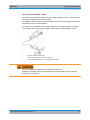
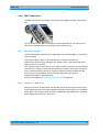
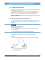
The BNC connectors are located on the left side of the R&S FSH behind a protective
cap.
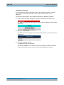
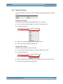
You can configure both BNC connectors for various applications. The names of the
connections are embossed on the insides of the protective caps.
2.4.6.1
EXT TRIG / EXT REF
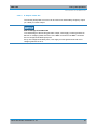
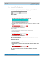
The first (upper) BNC connector is for application of an external trigger or an external
reference signal.
The external trigger is only for input configuration. It controls the start of a
measurement and has to be selected in the "Sweep" menu. The trigger threshold is
similar to that of TTL signals.
The 10 MHz reference signal that you can apply is used for frequency synchronization.
The level of the reference signal must be larger than 0 dBm. If the input is configured
for the external reference and but no reference signal is present, the R&S FSH will
show a warning in the display. This is to prevent users from carrying out a
measurement without a valid reference.
For more information see "Configuring the R&S FSH" on page 26.
2.4.6.2
BIAS Port 1 / BIAS Port 2
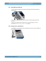
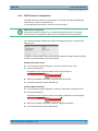
When you use them as BIAS ports, the two BNC connectors are direct current inputs.
Active equipment under test can be supplied with power via the BIAS Port 1 and BIAS
Port 2 direct current inputs. Direct current is supplied with the assistance of a suitable
power adapter (600 mA max. / 50 V max.).
Quick Start Guide 1309.6269.12 - 07
19