1
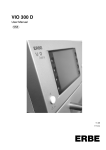
VIO 100 C V 1.0.x
VIO 50 C V 1.0.x
07.10
Service Manual
ERBE
SERVICE MANUAL
VIO 100 C
VIO 50 C
Service manual Art. No. 80116-221
All rights to this manual, in particular rights of duplication, dissemination and translation, are reserved. No part of
this manual may be reproduced in any form (by photocopying, microfilming or other methods) or processed, duplicated or disseminated by the use of electronic systems without the written consent of ERBE Elektromedizin GmbH.
The information contained in this manual may be amended or supplemented without prior notice and represents
no obligation on the part of ERBE Elektromedizin GmbH.
Printed by ERBE Elektromedizin
Printed in Germany
Copyright © ERBE Elektromedizin GmbH, Tübingen 2010
TABLE OF CONTENTS
Table of Contents
Chapter
1
Title
Page
Safety information.......................................................................... 7
Classification of the safety information ........................................................7
Knowledge of the User Manual....................................................................7
Protection from the risk of electric shock .....................................................7
Electrostatically sensitive components ........................................................8
Liability and warranty ...................................................................................8
2
Controls........................................................................................... 9
Controls at the front .....................................................................................9
Art.-Nr.: 80116-221
07.10
Controls at the rear ....................................................................................10
3
Technical Data .............................................................................. 11
4
Service mode ................................................................................ 13
General information ...................................................................................13
Setup overview ..........................................................................................13
Service overview........................................................................................15
Call up Service mode.................................................................................17
Exit Service mode ......................................................................................18
5
Remedying malfunctions............................................................. 19
Safety information ......................................................................................19
Error messages .........................................................................................19
5 / 40
TABLE OF CONTENTS
6
Maintenance and servicing.......................................................... 25
Who is allowed to perform servicing and maintenance work? .................. 25
What is a safety check? ............................................................................ 25
How often does a safety check have to be performed? ............................ 25
Art.-Nr.: 80116-221
04.10
Safety check – step by step ...................................................................... 26
Safety information................................................................................. 26
Testing and measuring equipment ....................................................... 27
User manual and visual inspections ..................................................... 28
Tests to be conducted in accordance with the national
specifications and regulations .............................................................. 28
DC resistance ....................................................................................... 29
Performance tests ................................................................................ 30
Footswitch activation ............................................................................ 31
Fingerswitch activation ......................................................................... 32
AUTO START mode (for VIO 100 C only)............................................ 33
HF power output CUT........................................................................... 34
HF power output COAGULATE............................................................ 36
Monitor circuits ..................................................................................... 39
6 / 40
1 • Safety information
CHAPTER 1
Safety information
Classification of the safety information
WARNING!
The WARNING! safety indication refers to a risk of personal injury.
CAUTION!
The CAUTION! safety indication refers to a risk of damage to property.
ATTENTION!
The ATTENTION! safety indication refers to a risk which can cause
equipment to become unserviceable.
IMPORTANT!
The IMPORTANT! designation indicates application information
and other particularly important information.
Knowledge of the User Manual
Art.-Nr.: 80116-221
07.10
The User Manual for this unit constitutes an integral part of this Service Manual. For performing servicing activities it is assumed that the
reader has knowledge of the User Manual, especially procedures for
installation, putting into operation, and handling.
Protection from the risk of electric shock
WARNING!
The supply voltage must match the voltage specified on the rating
plate. Connect the unit / the equipment cart to a properly installed
grounded outlet. Only use the ERBE power cord or an equivalent
power cord for this purpose. The power cord must bear the
national test symbol.
For safety reasons, multiple outlets and extension cords should
not be used. If their use is unavoidable, they also must be provided
with proper grounding.
WARNING!
Unplug the power cord from the outlet before exchanging parts of
the unit or cleaning it.
7 / 40
1 • Safety information
WARNING!
Do not plug a wet power cord into the unit or into an outlet.
WARNING!
Do not touch any unprotected wires or conductive surfaces while
the unit is opened and under voltage.
WARNING!
Blown line fuses may only be replaced by a competent technician.
Only replacement fuses of the rating specified on the unit's name
plate may be used. Before resuming operation the unit must be
subjected to a performance test by a competent technician.
Electrostatically sensitive components
CAUTION!
This unit contains electrostatically sensitive components. Work at
an anti-static workplace while repairing the unit. Wear a grounding
armband while working with electrostatically sensitive components. Hold the circuit boards by their non-conducting corners.
Use an anti-static container for transporting electrostatically sensitive components and the circuit boards.
ATTENTION!
Adjustments, tests, modifications, maintenance and repair work
may only be performed by ERBE or persons trained by ERBE. If
the work is not performed by trained persons, ERBE accepts no
liability and warranty rights become void.
It is recommended that the safety check also be performed by
ERBE or persons trained by ERBE.
ATTENTION!
8 / 40
Only use original ERBE spare parts. The manufacturer accepts no
liability and the warranty rights becomes void if original spare parts
are not used.
Art.-Nr.: 80116-221
07.10
Liability and warranty
2 • Controls
CHAPTER 2
Controls
IMPORTANT!
This chapter contains an overview of the controls of the unit(s).
The relevant User Manual for the unit(s), knowledge of which is
assumed for servicing work, provides detailed information about
how to use the unit(s).
Controls at the front
Art.-Nr.: 80116-221
07.10
ERBE
8
2
5
3
6
4
7
9
1
Fig. 2-1
1
Power Switch
2
Selection button for programs
3
Selection button (CUT)
4
Selection button (COAG)
5
Selection button for activation type
6
Plus/Minus buttons (CUT)
7
Plus/Minus buttons (COAG)
8
Focus button for bipolar receptacle
9
Focus button for monopolar receptacle
Footswitch indicator light
AUTO START indicator light
Return electrode indicator light
9 / 40
2 • Controls
Controls at the rear
1
2
3
10 / 40
1
Potential equalization terminal
2
Footswitch socket
3
Power supply module with fuses
Art.-Nr.: 80116-221
07.10
Abb. 2-2
3 • Technical Data
CHAPTER 3
Technical Data
Power connection
Rated supply voltage
100 V to 240 V (± 10 %)
Rated supply frequency
50 / 60 Hz
Line current
Max. 2.0 A
Power input in standby mode
< 15 watts
Power input with max. HF output
190 watts / 200 VA
Terminal for grounding (potential equalization)
Yes
Power fuses
T4A
Art.-Nr.: 80116-221
07.10
Operating mode
Intermittent operation
Duty cycle 25% (10 s ON / 30 s OFF)
Dimensions and weight
Width x height x depth
280 x 135 x 300 mm
Weight
4.0 kg
Ambient conditions for transport and storage of unit
Temperature
-40 °C to + 70 °C
Relative humidity
10% – 95%
Ambient conditions for operation of unit
Temperature
+10 °C to + 40 °C
Relative humidity
15% – 80%, noncondensing
11 / 40
3 • Technical Data
Acclimatizing
If the unit has been stored or transported at temperatures below +10 °C or above +40 °C, the unit will
require approx. 3 hours to acclimatize at room temperature.
Standards
II b
Protection class as per EN 60 601-1
I
Type as per EN 60 601-1
CF
Art.-Nr.: 80116-221
07.10
Classification according to EC Directive 93/42/
EEC
12 / 40
4 • Service mode
CHAPTER 4
Service mode
General information
This unit has a service mode with two levels:
• Level 1 = Setup (adjustment of settings that affect the operation of
the unit, e.g. display brightness)
• Level 2 = Service (adjustment of settings that affect the operation
of the unit + service settings + test programs)
Setup overview
Designation
Description
Use
1
Volume for
CUT activation
Volume setting of
the CUT activation
tones in 10 levels.
Activate setup:
Press the yellow selection button.
The current setting appears in the
blue display.
Change settings:
Press the blue Plus/Minus buttons. The setting change appears
in the blue display.
Save setting
change:
Press and hold the top left selection button until a check mark in
the adjacent display indicates the
end of the process.
Exit setup:
Press the yellow selection button
again. The settings display goes
out in the blue display.
Art.-Nr.: 80116-221
07.10
No.
2
Volume for
COAG activation
Volume setting of
the COAG activation tones in
10 levels.
13 / 40
No.
Designation
Description
Use
3
Volume button
Volume setting of
the buttons in 10
levels.
Activate setup:
Press the yellow selection button.
The current setting appears in the
blue display.
Change settings:
Press the blue Plus/Minus buttons. The setting change appears
in the blue display.
Save setting
change:
Press and hold the top left selection button until a check mark in
the adjacent display indicates the
end of the process.
Exit setup:
Press the yellow selection button
again. The settings display goes
out in the blue display.
4
5
14 / 40
Warning
tone volume
Display
brightness
Volume setting of
the warning tones
in 8 levels.
Selection of the
display brightness
in 10 levels.
Art.-Nr.: 80116-221
07.10
4 • Service mode
4 • Service mode
Service overview
Art.-Nr.: 80116-221
07.10
ATTENTION!
In this table, service programs are described that are used for
basic servicing work. In addition, the service level provides a
series of test programs with a number of diagnostic and inspection
options in the unit. Test programs are described in the repair
instructions and may not be used without precise knowledge of
their function.
No.
Designation
Description
Use
1–5
Setup programs
Repeat of setup programs 1 – 5 from service level 1.
6 – 19
Not assigned.
20
Reset
Front panel reset to
default values
(=default values for
programs, setup
and service settings, clearing the
error list).
Perform reset:
Press the yellow selection button.
The S (for Service mode) appears
with an asterisk in the top left display. Now press and hold the top
left selection button until a check
mark appears in the top left display.
21
Error list
Saves up to
20 errors.
Display error list:
Press the yellow selection button.
The error number appears in the
yellow display, the associated
error code in the blue display. The
yellow Plus/Minus buttons can be
used to switch between errors.
Clear error list:
Press and hold the top left selection button until a check mark in
the adjacent display indicates the
end of the process.
Exit service program.
Press the yellow selection button
until only the number of the service program appears in the yellow display.
15 / 40
No.
Designation
Description
Use
22
Activation
period limit
Setting of the unit
activation period
between 1 and
99 seconds.
Activate service
program:
Press the yellow selection button.
The current setting appears in the
blue display.
Change settings:
Press the blue Plus/Minus buttons. The setting change appears
in the blue display.
Save setting
change:
Press and hold the top left selection button until a check mark in
the adjacent display indicates the
end of the process.
Exit service program.
Press the yellow selection button
until only the number of the service program appears in the yellow display.
23
Test program -> Description, see repair instructions.
24
Test program -> Description, see repair instructions.
25
Software
version
Display of the software version of the
unit.
Display software
version:
Press the yellow selection button.
The three-digit software version
appears (first and second digit in
the yellow display, third digit in the
blue display).
Exit service program:
Press the yellow selection button
until only the number of the service program appears in the yellow display.
26
Test program -> Description, see repair instructions.
27
Activation
type
16 / 40
Setting of the
AUTO START activation, ON or OFF.
Set activation
type:
Press the yellow selection button.
The current setting appears in the
top right display (AUTO ON or
AUTO OFF). The top right selection button is used to switch
between settings.
Save setting
change:
Press and hold the top left selection button until a check mark in
the adjacent display indicates the
end of the process.
Exit service program.
Press the yellow selection button
until only the number of the service program appears in the yellow display.
Art.-Nr.: 80116-221
07.10
4 • Service mode
4 • Service mode
No.
Designation
Description
Use
28
Return electrode resistance
Display of return
electrode resistance values.
Display NE resistance:
Press the yellow selection button.
The current NE resistance
appears in the blue display.
Exit service program:
Press the yellow selection button
until only the number of the service program appears in the yellow display.
29
Test program -> Description, see repair instructions.
30
Test program -> Description, see repair instructions.
31
Test program -> Description, see repair instructions.
Call up Service mode
Call up Setup
Art.-Nr.: 80116-221
07.10
ERBE
1. When switching on the unit, press and hold the top left selection
button. The unit switches on to the Setup and shows <Setup 1>
in the yellow display. The yellow Plus/Minus buttons can be used
to switch between setup settings. For more about setup settings,
see table on page 13.
Call up Service
ERBE
1. When switching on the unit, press and hold the top left selection
button. The unit switches to the Setup.
17 / 40
4 • Service mode
ERBE
100 C
2. Press and hold the three buttons as illustrated above. The unit
switches on to the service level and shows an <S> in the top left
display. The yellow Plus/Minus buttons can be used to switch
between service programs. For more about service programs,
see table on page 15.
Exit Service mode
Art.-Nr.: 80116-221
07.10
Switch the unit off.
18 / 40
5 • Remedying malfunctions
CHAPTER 5
Remedying malfunctions
Safety information
ATTENTION!
Adjustments, technical tests, modifications, maintenance and
repair work may only be performed by ERBE or persons trained by
ERBE. If the work is not performed by trained persons, ERBE
accepts no liability and warranty rights become void.
Art.-Nr.: 80116-221
07.10
Error messages
Error
code
Description
Additional information
Action
1
Reaching the activation period
limit.
If the activation period limit
has been set too short, service program 22 can be used
to extend it.
2
NE monitoring returns an illegal
value at or during monopolar activation.
Check whether the NE is
applied correctly and connected to the unit.
Check whether the NE cable
is connected correctly and in
good condition.
If the error still occurs, notify
ERBE Service.
3
Activating the unit without prior
acknowledgement of the front
panel setting.
Press any button to acknowledge the settings of the front
panel and then reactivate the
unit.
4
Activation of CUT with no defined
power setting.
CUT power setting
> Select 0 watts before activating the unit.
5
Activation of COAG with no
defined power setting.
COAG power setting
> Select 0 watts before activating the unit.
19 / 40
5 • Remedying malfunctions
Error
code
Description
6
A button on the front panel is
pressed when an activation
request occurs.
Additional information
Action
Do not activate the unit when
making settings on the front
panel.
If the error still occurs, notify
ERBE Service.
7
8
Restart the unit. If the error
occurs again, notify ERBE
Service.
Several activation signals are
pending simultaneously.
Actuate only one activation
signal (footswitch or fingerswitch).
Check the correct function of
the fingerswitches and footswitches.
If the error still occurs, notify
ERBE Service.
Activation source (=footswitch)
was not assigned.
The footswitch
must first be
assigned to an output socket before
the footswitch can
be used for activation.
10 – 18
19
Assign the footswitch of the
required output socket.
Art.-Nr.: 80116-221
07.10
9
Restart the unit. If the error
occurs again, notify ERBE
Service.
After assigning the AUTO START
function, an activation was
detected within a period of 200 ms.
Occurs when an
electrically conductive contact exists
between the electrodes of the connected instruments
during AUTO
START assignment.
Check the connecting cable
to the forceps or forceps for
short-circuit.
Ensure that there is no electrically conductive contact
between the forcep branches
during AUTO START assignment; place the forceps on an
insulated base and open the
forcep branches (electrical
contact is interrupted).
If the error still occurs, notify
ERBE Service.
20 / 40
5 • Remedying malfunctions
Error
code
Description
20
The CUT footswitch pedal was
pressed when switching on the
unit.
Additional information
Action
Do not press the CUT footswitch pedal when switching
on the unit.
Check the correct function of
the footswitch.
If the error still occurs, notify
ERBE Service.
21
The COAG footswitch pedal was
pressed when switching on the
unit.
Do not press the COAG footswitch pedal when switching
on the unit.
Check the correct function of
the footswitch.
If the error still occurs, notify
ERBE Service.
Art.-Nr.: 80116-221
07.10
22
The CUT fingerswitch was pressed
when switching on the unit.
Do not press the CUT fingerswitch when switching on the
unit.
Check the correct function of
the fingerswitch.
If the error still occurs, notify
ERBE Service.
23
The COAG fingerswitch was
pressed when switching on the
unit.
Do not press the COAG fingerswitch when switching on
the unit.
Check the correct function of
the fingerswitch.
If the error still occurs, notify
ERBE Service.
24
The selection button (CUT) was
pressed when switching on the
unit.
Check whether the corresponding button was pressed
when switching on the unit.
If not, notify ERBE Service.
25
Only for V 1.0.0: The selection button (COAG) was pressed when
switching on the unit.
Check whether the corresponding button was pressed
when switching on the unit.
If not, notify ERBE Service.
26
The selection button for activation
type was pressed when switching
on the unit.
Check whether the corresponding button was pressed
when switching on the unit.
If not, notify ERBE Service.
21 / 40
5 • Remedying malfunctions
Description
27
The Plus selection button (CUT)
was pressed when switching on
the unit.
Check whether the corresponding button was pressed
when switching on the unit.
If not, notify ERBE Service.
28
The Minus selection button (CUT)
was pressed when switching on
the unit.
Check whether the corresponding button was pressed
when switching on the unit.
If not, notify ERBE Service.
29
The Plus selection button (COAG)
was pressed when switching on
the unit.
Check whether the corresponding button was pressed
when switching on the unit.
If not, notify ERBE Service.
30
The Minus selection button
(COAG) was pressed when switching on the unit.
Check whether the corresponding button was pressed
when switching on the unit.
If not, notify ERBE Service.
31
The focus button for bipolar receptacle was pressed when switching
on the unit.
Check whether the corresponding button was pressed
when switching on the unit.
If not, notify ERBE Service.
32
The focus button for monopolar
receptacle was pressed when
switching on the unit.
Check whether the corresponding button was pressed
when switching on the unit.
If not, notify ERBE Service.
33
More than one button was pressed
when switching on the unit.
Check whether buttons were
pressed when switching on
the unit.
If not, notify ERBE Service.
34 – 42
43
Additional information
Action
Restart the unit. If the error
occurs again, notify ERBE
Service.
The unit temperature is outside the
operational range.
If the temperature is too high,
allow the unit to cool down.
If the temperature is too low,
allow the unit to acclimate to
room temperature.
If the error still occurs, notify
ERBE Service.
44 – 50
22 / 40
Restart the unit. If the error
occurs again, notify ERBE
Service.
Art.-Nr.: 80116-221
07.10
Error
code
5 • Remedying malfunctions
Error
code
Description
Additional information
Art.-Nr.: 80116-221
07.10
60 + 61
Action
Restart the unit. If the error
occurs again, notify ERBE
Service.
62
The user interface settings are not
stored in the EEPROM. Default
programs are used (and the
default settings for Setup and Service).
User programs cannot be saved.
Attempt to resave user programs. If not possible, notify
ERBE Service.
63
Error when writing to the external
EEPROM.
Attempt to save the user program again. If not possible,
notify ERBE Service.
64
Error when reading the external
EEPROM.
Attempt to read the user program again. If not possible,
notify ERBE Service.
70
Restart the unit. If the error
occurs again, notify ERBE
Service.
80 + 81
Restart the unit. If the error
occurs again, notify ERBE
Service.
94
Microcontroller Flash data is
invalid.
Invalid software
may have been
installed.
Have the mainboard reprogrammed (by Technical Service Germany only).
23 / 40
Art.-Nr.: 80116-221
07.10
5 • Remedying malfunctions
24 / 40
6 • Maintenance and servicing
CHAPTER 6
Maintenance and servicing
Who is allowed to perform servicing and maintenance work?
ATTENTION!
Adjustments, tests, modifications, maintenance and repair work
may only be performed by ERBE or persons trained by ERBE. If
the work is not performed by trained persons, ERBE accepts no
liability and warranty rights become void.
It is recommended that the safety check also be performed by
ERBE or persons trained by ERBE.
What is a safety check?
Art.-Nr.: 80116-221
07.10
IMPORTANT!
The safety check is a preventive measure to examine whether the
device is safe and ready for operation. In order to perform the various tests the current specifications and regulations of the particular country and the instructions in this service manual must be
observed.
How often does a safety check have to be performed?
IMPORTANT!
ERBE recommends performing a safety check after every repair,
but at least once a year.
25 / 40
6 • Maintenance and servicing
Safety check – step by step
For simplification the device to be tested is referred to below as the
"test specimen".
Safety information
26 / 40
For safety reasons (personnel protection) the test specimen
should generally be operated by a suitable isolating transformer.
An exceptional case is the tests for grounded conductor resistance, ground leakage current, and patient leakage current, in
which the test specimen is supplied with current via the safety
tester.
ATTENTION!
In the event of a fault occurring in the test specimen or individual
components during the safety check the test steps taken so far no
longer apply. Remedy the defect and repeat the safety check from
the beginning.
ATTENTION!
The specifications made in this chapter for the test programs allow
the service technician to perform the safety check. In addition, the
test programs provide a number of diagnostic and inspection
options in the unit; detailed descriptions are available in the repair
instructions. ERBE expressly states that the full functional range of
the test programs may not be used without precise knowledge of
the test programs.
IMPORTANT!
It is assumed that the user knows how to operate the test specimen, the test equipment, the measuring equipment, and auxiliary
test equipment. The test instructions only apply in conjunction with
the relevant test steps.
IMPORTANT!
Test equipment, measuring equipment, and auxiliary test equipment (cables, test boxes, etc.) are listed separately at the beginning of each test unit. Where ERBE article numbers are specified,
only original ERBE test equipment, measuring equipment, and
auxiliary test equipment may be used.
IMPORTANT!
The test report for the safety check can be requested from ERBE
Technical Service Tübingen. For the address see address sheet
on last page.
Art.-Nr.: 80116-221
07.10
WARNING!
6 • Maintenance and servicing
Testing and measuring equipment
IMPORTANT!
The following list contains the testing and measuring equipment
recommended by ERBE for servicing. Where ERBE article numbers are specified, only original ERBE testing and measuring
equipment should be used.
ERBE
Art. No.
–
Safety tester (with insulation testing >500 V
DC)
–
HF power meter
(recommended: Metron QA-ES or Fluke QAES)
20189-107
Two pedal footswitch VIO C
20190-045
Electrode handle ICC/ACC
20192-127
Patient cable AE
20192-110
Patient cable AE, international
–
Art.-Nr.: 80116-221
07.10
Description
Laboratory measuring cable
20196-045
Bipolar cable
20196-053
Bipolar cable, international
20100-034
Adapter cable bipolar
20194-070
Patient cable NE
20194-075
Patient cable NE, international
20100-033
Adapter cable NE
20100-035
Cable LF – leakage current
20100-038
Cable LF – leakage current, international
20100-101
VIO Testbox Symmetry/Resistance (NE
asymmetry/critical resistance)
20100-102
VIO Testbox Auto Start/Auto Stop (bipolar
start/stop)
27 / 40
6 • Maintenance and servicing
User manual and visual inspections
• Test specimen and accessories (where enclosed) undamaged
externally.
• User manual present.
• All labels on the test specimen (conformity declaration mark, rating plate, and all wording) present and readily legible.
Tests to be conducted in accordance with the
national specifications and regulations
Grounded conductor test
• Ground terminal to chassis.
• Ground terminal to potential equalization pin.
Ground leakage current
measurement
• Ground leakage current, normal condition (N.C.).
• Ground leakage current, single-fault condition (S.F.C.).
Patient leakage current measurement
• Patient leakage current, normal condition (N.C.).
• Patient leakage current, single-fault condition (S.F.C.).
IMPORTANT! Close the output relay of the unit for testing the patient
1. Call up service level (see page 17).
2. Use the Plus/Minus button to select and the yellow selection button to activate the test program <Setup 24>.
3. Close the relay of the bipolar receptacle. Use the Plus/Minus buttons next to the CUT and COAG displays and perform the following settings:
– CUT display: <Setup 1> (= bipolar receptacle)
– COAG display:
4. Close the relay of the monopolar receptacle. Use the Plus/Minus
buttons next to the CUT and COAG displays and perform the following settings:
– CUT display: <Setup 2> (= monopolar receptacle)
– COAG display:
5. Perform the measurement.
6. Switch the test specimen off.
28 / 40
Art.-Nr.: 80116-221
07.10
leakage current. On the test specimen:
6 • Maintenance and servicing
DC resistance
Testing and measuring equipment
ERBE
Art. No.
20192-127
Description
Patient cable AE
or
20192-110
Patient cable AE, international
–
Laboratory measuring cable
20190-045
Electrode handle ICC/ACC
20194-070
Patient cable NE
or
20194-075
Patient cable NE, international
20100-033
Adapter cable NE
Art.-Nr.: 80116-221
07.10
–
Safety tester (with insulation testing
>500 V DC)
Test setup
WARNING!
Across the measuring lines there is the DC voltage of 500 V! In
order to avoid injuries, only switch on the test specimen and safety
tester when all the electrical connections have been made.
+
+
Fig. 6-1
• The test specimen is connected to the power supply via the power
cord.
• The NE receptacle of the test specimen is connected to the safety
tester via the patient cable NE with the adapter cord.
• The AE receptacle of the test specimen is connected to the safety
tester via the patient cable AE and the electrode handle with the
laboratory measuring cable.
29 / 40
6 • Maintenance and servicing
Test procedure
1. Start safety tester in the "Insulation resistance" function The
measured value displayed should be >200 MOhm.
2. Start the test specimen and call up test program <Setup 24>.
3. Close all output relays of the test specimen in the test program
<Setup 24>.
4. Determine insulation resistance using the safety tester. The
measured value must be >2 MOhm.
5. Document the measured value.
6. Exit the test program <Setup 24>. Switch the test specimen off.
Performance tests
Testing and measuring equipment
ERBE
Art. No.
Description
20189-107
Two pedal footswitch VIO C
20194-070
Patient cable NE
20194-075
Patient cable NE, international
20100-033
Adapter cable NE
Test setup
• The test specimen is connected to the power supply via the power
cord.
• The dual-pedal footswitch is connected.
• The NE patient cable with the shorted adapter cable is connected
to the NE receptacle on the test specimen.
Test procedure
30 / 40
Power switch
1. Check power switch for smooth operation. The power switch
must be easy to operate and must neither stick nor scrape.
2. Press power switch. The power switch must snap into the "ON"
position and the test specimen must perform a system start.
Start routine /
acknowledgement tone
1. The test specimen must perform the system start without error
message(s).
2. The test specimen must emit an acoustic signal (acknowledgement tone) during the self-test.
Art.-Nr.: 80116-221
07.10
or
6 • Maintenance and servicing
Pushbuttons / acknowledgement tone when pressed
Display / LEDs
1. Check all the pushbuttons (focus buttons, selection buttons,
+/– buttons) on the test specimen to make sure they are working
properly. Press each button at least twice. When pressing the
buttons there must be an acoustic signal every time
(= acknowledgement tone).
Display:
1. Check the backlighting of the display to make sure it is operating
properly. If backlighting is faulty, no image will be visible.
LEDs:
1. When starting the system, all LEDs must briefly light up at the
same intensity.
Activation tones
1. Press CUT pedal on the dual-pedal footswitch at least twice.
When pressing the pedal there must be an acoustic signal every
time (= acknowledgement tone).
2. Press COAG pedal on the dual-pedal footswitch at least twice.
When pressing the pedal there must be an acoustic signal every
time (= acknowledgement tone).
Footswitch activation
Art.-Nr.: 80116-221
07.10
Testing and measuring equipment
ERBE
Art. No.
20189-107
Description
Two pedal footswitch VIO C
Test setup
• The test specimen is connected to the power supply via the power
cord.
• The dual-pedal footswitch is connected.
Test procedure
Call up
test program
1. Call up service level (see page 17).
2. Use the Plus/Minus button to select and the yellow selection button to activate the test program <Setup 26>.
31 / 40
6 • Maintenance and servicing
Dual-pedal footswitch
activation CUT / COAG
1. Press the CUT pedal on the two pedal footswitch. The "X" character must appear in the left segment in the CUT display 1 during
activation.
2. Press the COAG pedal on the two pedal footswitch. The "X"
character must appear in the right segment in the CUT display
during activation.
3. Remain in the Test program.
Fingerswitch activation
Testing and measuring equipment
ERBE
Art. No.
20192-127
Description
Patient cable AE
or
20192-110
Patient cable AE, international
20190-045
Electrode handle ICC/ACC
• The test specimen is connected to the power supply via the power
cord.
Test procedure
Electrode handle
Activation CUT / COAG
Exit test program
1. Connect the electrode handle with patient cable AE to the
Monopolar receptacle of the test specimen.
2. Press the CUT button on the electrode handle. The "X" character
must appear in the left segment in the COAG display 2 during
activation.
3. Press the COAG button on the electrode handle. The "X" character must appear in the right segment in the COAG display during
activation.
4. Remove the electrode handle.
1. Switch the test specimen off.
1. Legend: "–" not yet activated, "X" successful activation, "0" = activation finished
2. Legend: "–" not yet activated, "X" successful activation, "0" = activation finished
32 / 40
Art.-Nr.: 80116-221
07.10
Test setup
6 • Maintenance and servicing
AUTO START mode (for VIO 100 C only)
Testing and measuring equipment
ERBE
Art. No.
Description
20196-045
Bipolar cable
or
20196-053
Bipolar cable, international
20100-034
Adapter cable bipolar
20100-102
VIO Testbox Auto Start/Auto Stop (bipolar
start/stop)
Test setup
Art.-Nr.: 80116-221
07.10
+
+
T1
BP1
T2
1
2
X
X
X
X
BP2
Testbox 20100-102
Fig. 6-2
• The test specimen is connected to the power supply via the power
cord.
• The Bipolar receptacle of the test specimen is connected to the
VIO Testbox via the bipolar cable with the adapter cable.
Test procedure
1. Activate AUTO START if necessary. To do so:
– Call up service level (see page 17)
– Use the Plus/Minus button to select and the yellow selection
button to activate <Setup 27>.
– Use the top right selection button to set <AUTO ON>.
– Save the setting. Press and hold the top left selection button
until a check mark in the adjacent display indicates the end of
the process.
– Exit Service mode. Switch the test specimen off.
33 / 40
6 • Maintenance and servicing
2. Switch the test specimen on and set to:
BIPOLAR SOFT, 50 Watt, AUTO START
3. Press and hold the T1 button on the VIO test box. The test specimen must start the activation.
4. Press button T2. The test specimen must terminate activation.
HF power output CUT
Testing and measuring equipment
ERBE
Art. No.
20192-127
Description
Patient cable AE
or
20192-110
Patient cable AE, international
–
Laboratory measuring cable
20190-045
Electrode handle ICC/ACC
20194-070
Patient cable NE
20194-075
Patient cable NE, international
20100-033
Adapter cable NE
–
20189-107
34 / 40
HF power meter
Two pedal footswitch VIO C
Art.-Nr.: 80116-221
07.10
or
6 • Maintenance and servicing
Test setup
+
AE
+
NE
HF power meter
Fig. 6-3
• The test specimen is connected to the power supply via the power
cord.
• The levels of power are determined with the HF power meter. The
measuring cables are plugged into the HF power meter direct.
Art.-Nr.: 80116-221
07.10
AUTO CUT
DRY CUT
Test procedure for VIO 50 C
1. Set the test specimen to:
AUTO CUT, 50 Watt
2. Set HF power meter to:
RL = 500 ohms
3. Activate test specimen via CUT button on the electrode handle.
4. Determine and document measured value. The tolerance range
is 40 to 60 watts.
1. Set the test specimen to:
DRY CUT, 50 Watt
2. Set HF power meter to:
RL = 500 ohms
3. Activate test specimen via CUT button on the electrode handle.
4. Determine and document measured value. The tolerance range
is 40 to 60 watts.
Test procedure for VIO 100 C
1. Set the test specimen to:
AUTO CUT, 100 Watt
2. Set HF power meter to:
RL = 500 ohms
3. Activate test specimen via CUT button on the electrode handle.
4. Determine and document the measured value. The tolerance
range is 80 to 120 watts.
35 / 40
6 • Maintenance and servicing
1. Set the test specimen to:
DRY CUT, 100 Watt
2. Set HF power meter to:
RL = 500 ohms
3. Activate test specimen via CUT button on the electrode handle.
4. Determine and document the measured value. The tolerance
range is 80 to 120 watts.
HF power output COAGULATE
Testing and measuring equipment
ERBE
Art. No.
20192-127
Description
Patient cable AE
or
20192-110
Patient cable AE, international
20190-045
Electrode handle ICC/ACC
–
Laboratory measuring cable
Patient cable NE
or
20194-075
Patient cable NE, international
20100-033
Adapter cable NE
20196-045
Bipolar cable
or
20196-053
Bipolar cable, international
20100-034
Adapter cable bipolar
–
20189-107
36 / 40
HF power meter
Two pedal footswitch VIO C
Art.-Nr.: 80116-221
07.10
20194-070
6 • Maintenance and servicing
SOFT COAG
FORCED COAG
Test setup
+
AE
+
NE
HF power meter
Fig. 6-4
• The test specimen is connected to the power supply via the power
cord.
• The levels of power are determined with the HF power meter. The
measuring cables are plugged into the HF power meter direct.
Art.-Nr.: 80116-221
07.10
Test procedure for VIO 50 C
1. Set the test specimen to:
SOFT COAG, 50 Watt
2. Set HF power meter to:
RL = 100 Ohm
3. Activate test specimen via COAG button on the electrode handle.
4. Determine and document measured value. The tolerance range
is 40 to 60 watts.
1. Set the test specimen to:
FORCED COAG, 50 Watt
2. Set HF power meter to:
RL = 500 ohms
3. Activate test specimen via COAG button on the electrode handle.
4. Determine and document measured value. The tolerance range
is 40 to 60 watts.
Test procedure for VIO 100 C
1. Set the test specimen to:
SOFT COAG, 80 Watt
2. Set HF power meter to:
RL = 100 Ohm
3. Activate test specimen via COAG button on the electrode handle.
4. Determine and document the measured value. The tolerance
range is 64 to 96 watts.
37 / 40
6 • Maintenance and servicing
1. Set the test specimen to:
FORCED COAG, 50 Watt
2. Set HF power meter to:
RL = 500 ohms
3. Activate test specimen via COAG button on the electrode handle.
4. Determine and document measured value. The tolerance range
is 40 to 60 watts.
BIPOLAR SOFT COAG
Test setup
+
+
Bipolar
HF power meter
• The test specimen is connected to the power supply via the power
cord.
• The levels of power are determined with the HF power meter. The
measuring cables are plugged into the HF power meter direct.
• The dual-pedal footswitch is connected.
Test procedure for VIO 50 C
1. Set the test specimen to:
BIPOLAR (=BIPOLAR SOFT COAG), 50 Watt
2. Set HF power meter to:
RL = 100 Ohm
3. Activate test specimen via COAG pedal on the footswitch.
4. Determine and document measured value. The tolerance range
is 40 to 60 watts.
Test procedure for VIO 100 C
1. Set the test specimen to:
BIPOLAR (=BIPOLAR SOFT COAG), 80 Watt
2. Set HF power meter to:
RL = 100 Ohm
3. Activate test specimen via COAG pedal on the footswitch.
4. Determine and document the measured value. The tolerance
range is 64 to 96 watts.
38 / 40
Art.-Nr.: 80116-221
07.10
Fig. 6-5
6 • Maintenance and servicing
Monitor circuits
NE monitoring of critical
resistance
for
dual surfaced
return electrodes
Testing and measuring equipment
ERBE
Art. No.
Description
20194-070
Patient cable NE
or
20194-075
Patient cable NE, international
20100-033
Adapter cable NE
20100-101
VIO Testbox Symmetry/Resistance (NE
asymmetry/critical resistance)
20189-107
Two pedal footswitch VIO C
Test set-up and test procedure
1st test step
Testbox 20100-101
3
4
6
7
8
9
10
11
1
Art.-Nr.: 80116-221
07.10
+
2
5
+
12
Fig. 6-6
• The test specimen is connected to the power supply via the power
cord.
• The test is performed without a load.
• The NE receptacle of the test specimen is connected to the VIO
Testbox via the patient cable NE with the adapter cable.
• The dual-pedal footswitch is connected.
1. Set the test specimen to:
AUTO CUT, 10 Watt
2. The return electrode indicator light must light up red on the test
specimen.
3. Activate AUTO CUT via the footswitch. The test specimen must
inhibit activation and emit or display an optical and acoustic
warning.
39 / 40
6 • Maintenance and servicing
2nd test step
Testbox 20100-101
3
4
6
7
8
9
10
11
1
+
2
5
+
12
Fig. 6-7
1. Keep the setting on the test specimen.
2. The return electrode indicator light must light up green on the
test specimen.
3. Activate AUTO CUT via the footswitch. It must be possible to
activate the test specimen without error or warning signals.
40 / 40
Art.-Nr.: 80116-221
07.10
• The test specimen is connected to the power supply via the power
cord.
• The test is performed without a load.
• The NE receptacle of the test specimen is connected to the VIO
Testbox via the patient cable NE with the adapter cable.
• The dual-pedal footswitch is connected.