1
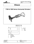
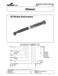
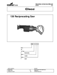
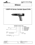
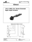
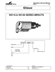
Operation & Service Manual
823008
2/01
1700 & 1900 Series Vertical Grinders
XX XX B
V
X
-
XX
Series:
17
19
Wheel Type:
1700
1900
RPM:
45
60
72
77
Generation:
B
Second
07
09
11
7" Type 27 or 28 Depressed Center Wheel
9" Type 27 Depressed Center Wheel
9" Type 28 Depressed Center Wheel
05
06
SS
5" Cup Type 6 or 11
6" Cup Type 6 or 11
Sanding Shroud
Type:
V
Vertical
Throttle Terminations:
L
Quick Release
Lever (Lock Off)
S
Self Closing Thumb
For additional product information visit our website at http://www.clecotools.com
NORTH AMERICA
CooperTools
P.O. Box 1410
Lexington, SC 29071
EUROPE
Cooper Power Tools GmbH & Co.
Postfach 30
D-73461 Westhausen
1
Safety Recommendations
For your safety and the safety of others, read and understand the
safety recommendations before operating any grinder.
Always wear protective equipment and clothing.
!
WARNING
Impact resistant eye protection
must be worn while operating
or working near this tool.
Caution: Faceshields do not provide unlimited protection against
flying particles and are not to be considered as eye protection.
ANSI Z87.1 states that separate eyewear shall be used. For
additional information on eye protection, refer to Federal OSHA
Regulations, 29 CFR, Section 1910.133, Eye and Face Protection, and ANSI Z87.1, Occupational and Educational Eye and
Face Protection. This standard is available from the American
National Standards Institute, Inc., 11 West 42nd Street, New
York, NY 10036.
!
CAUTION
Personal hearing protection is
recommended when operating
or working near this tool.
Hearing protection is recommended in high noise areas (above
85 dBA). Close proximity of additional tools, reflective surfaces,
process noises, and resonant structures can substantially contribute to the sound level experienced by the operator. Excessive
air pressure (greater than 90 psig) or worn components can also
increase sound level emitted by the tool. Proper hearing conservation measures, including annual audiograms and training in
the use and fit of hearing protection devices may be necessary.
For additional information on hearing protection, refer to Federal
OSHA Regulations, 29 CFR, Section 1910.95, Occupational
Noise Exposure, and American National Standards Institute,
ANSI S12.6, Hearing Protectors.
• Gloves and other protective clothing should be worn as
required.
• Do not wear clothing that may restrict movement, become
entangled or in any way interfere with the safe operation of
grinders.
2
!
WARNING
Wear respirator where
necessary.
Grinding or other applications of this tool may produce hazardous fumes and/or dust. To avoid adverse health effects utilize
adequate ventilation and/or a respirator. Respirators should be
selected, fitted, used and maintained in accordance with Occupational Safety and Health Administration and other applicable
regulations. Read the material safety data sheet of any materials
involved in the grinding process.
Cleco grinders should be operated with 90 psig (6.2 bar) max. air
pressure. Excessive air pressure increases the loads and stresses
on the tool parts and may result in breakage. Installation of a
filter-regulator-lubricator in the air supply line is highly recommended.
Never use the air hose for supporting, lifting, or lowering the tool.
Use a safety line or cable on the tool when working in elevated
areas.
Before tool is connected to air supply, check throttle for proper
operation, i.e., throttle moves freely and returns to closed position. Being careful not to endanger adjacent personnel, clear air
hose of accumulated dust and moisture. Use protective barriers
where necessary — hot sparks can burn. Barriers also help
reduce noise levels. Before removing tool from service or changing accessories, make sure air line is shut off and drained of air
to prevent the tool from operating if the throttle is accidently
engaged. The use of a self-relieving valve for this purpose is
highly recommended.
Wheel guards are used to prevent serious injury to the operator
in the event of wheel failure and must not be modified in any way.
Any wheel guard that is damaged or bent must be replaced.
Grinders must be held so that the opening in the guard is away
from the operator.
The guard must be attached to the grinder with all bolts, nuts and
lockwashers in place and torqued to 144 - 156 in. lbs..
Safety Recommendations
OVER
Repetitive work motions and/or vibration
can cause injury to hands and arms.
Use minimum hand grip force consistent with
proper control and safe operation.
Keep body and hands warm and dry.
Avoid anything that inhibits blood circulation.
Avoid continuous vibration exposure.
Keep wrists straight.
Avoid repeated bending of wrists and hands.
CAUTION
WARNING
WARNING
!
!
!
Personal hearing protection is
recommended when operating
or working near this tool.
Impact resistant eye protection
must be worn while operating
or working near this tool.
Hearing protection is recommended in high noise
areas (above 85 dBA). Close proximity of other
tools, reflective surfaces, process noises, and
resonant structures can substantially contribute
to the sound level experienced by the user.
Do not remove this tag until
the operator of this tool has
read these safety precautions.
202408
WARNING AND
INSTRUCTION LABEL
• Improper shipment or storage
• Exposure to water, solvents, high humidity,
freezing and extreme temperatures
• Mismatched speed ratings
• Age
869974
WARNING TAG
Read Operating Instructions carefully. Follow
the Safety Recommendations for your safety
and the safety of others.
203011
WARNING TAG
Abrasive wheels known to have been subjected to any of the
above conditions can violently disintegrate. Never operate
a vertical grinder without proper wheel guard in place.
0
CHECK FLANGE
1
2
3
6
4
5
TACHOMETER
203208
SPEED RATING
AND WARNING TAG
Speed rating, warning tags and warning labels should be maintained or replaced for legibility in the event of damage. Speed
rating, warning tags, and warning labels are available from the
manufacturer.
Before mounting a wheel, after all tool repairs, and whenever a
grinder is issued for use, check the free speed of the grinder with
a tachometer to make certain that the actual free speed at 90 psig
(6.2 bar) does not exceed the rated free speed stamped on the
tool. Grinders in use on the job must be checked at least once
every twenty hours of operation, or once every week, whichever
is more frequent. Checking free speed after the removal of each
worn wheel and before mounting a new wheel is highly recommended.
Check the grinder spindle and driving flange for signs of damage
or abuse. A vertical grinder driving flange must be flat, unrelieved, and free of nicks and burrs. The spindle must not be bent,
and the threads should be free of any damage that might keep
an abrasive wheel and its mount from locating centrally or
seating properly against the driving flange.
ABRASIVE WHEEL MOUNTING & BEGINNING GRINDING
OPERATION
Sufficiently tighten wheel to prevent spin-off. Do not overtighten, and do not install wheel by spinning it on by throttling the
tool. This is a dangerous practice and can cause spindle damage
or breakage. Always use a wheel retainer on a Type 6 or 11 cup
wheel.
Before beginning operations or after mounting a wheel, run the
tool for one (1) minute in a protected enclosure to check the
integrity or the wheel. During this time or any other time, no one
should stand in front of or in line of the wheel. When starting work
with a cold wheel, apply it gradually to the workpiece until the
wheel becomes warm.
INSPECT THE GRINDING WHEEL!
Check the maximum safe RPM marked on the wheel. Never use
a wheel rated below the actual tool speed. Inspect the wheel
for cracks or chips, water stains, or signs of abuse or improper
storage. Cracked, chipped or faulty grinding wheels are
dangerous and must not be used. They must be destroyed
rather than risk their use by someone who may not notice that
they are damaged.
!
WARNING
Fragments from an abrasive wheel
can cause serious injury or death.
Do not operate without proper
wheel guard in place.
Causes of abrasive wheel failures have been traced to such
factors as:
• Dropping, bumping, or abuse (careless handling
of the grinder or wheel)
• Improper mounting
• Imbalance
When the remaining portion of a Type 6 or 11 cup wheel can no
longer be used, do not use a hammer to break up the remaining
"rock" so that it can be removed. This is a dangerous practice and
can lead to spindle damage or breakage. Instead use a back-up
wrench on the flange, and a strap wrench.
DO NOT CONTINUE TO USE A GRINDER IF:
• It is not equipped with the proper wheel guard
• The speed rating of the wheel is less than the
speed of the grinder
• It starts to vibrate
• You sense any changes in tool speed or an
unusual increase in noise output that would
indicate the tool is running at excessive speed
• You notice excessive end play in the spindle
• You hear any unusual sound from the grinder
RETURN THE TOOL TO THE TOOL CRIB FOR SERVICE
IMMEDIATELY!
3
Safety Recommendations
!
WARNING
Repetitive work motions and/or vibration
can cause injury to hands and arms.
Use minimum hand grip force.
Keep body and hands warm and dry.
Avoid anything that inhibits blood curculation.
Avoid continuous vibration exposure.
Keep wrists straight.
Avoid repeated bending of wrists and hands.
Some individuals may be susceptible to disorders of the
hands and arms when performing tasks consisting of highly
repetitive motions and/or exposure to extended vibration.
Cumulative trauma disorders such as carpal tunnel syndrome and tendonitis may be caused or aggravated by
repetitious, forceful exertions of the hands and arms.
Vibration may contribute to a condition called Raynaud's
Syndrome. These disorders develop gradually over periods of weeks, months, and years. It is presently unknown
to what extent exposure to vibrations or repetitive motions
may contribute to the disorders. Hereditary factors,
vasculatory or circulatory problems, exposure to cold and
dampness, diet, smoking and work practices are thought to
contribute to the conditions.
Tool operators should be aware of the following warning
signs and symptoms so that a problem can be addressed
before it becomes a debilitating injury. Any user suffering
prolonged symptoms of tingling, numbness, blanching of
fingers, clumsiness or weakened grip, nightly pain in the
hand, or any other disorder of the shoulders, arms, wrists,
or fingers is advised to consult a physician. If it is determined that the symptoms are job related or aggravated by
movements and postures dictated by the job design, it may
be necessary for the employer to take steps to prevent
further occurrences. These steps might include, but are not
limited to, repositioning the workpiece or redesigning the
workstation, reassigning workers to other jobs, rotating
jobs, changing work pace, and/or changing the type of tool
used so as to minimize stress on the operator. Some tasks
may require more than one type of tool to obtain the
optimum operator/tool/task relationship.
The following suggestions will help reduce or moderate the
effects of repetitive work motions and/or extended vibration
exposure:
• Use a minimum hand grip force consistent with
proper control and safe operation
• Keep body and hands warm and dry (cold weather
is reported to be a major factor contributing to
Raynaud's Syndrome)
• Tasks should be performed in such a manner that
the wrists are maintained in a neutral position,
which is not flexed, hyperextended, or turned side
to side
4
• Avoid anything that inhibits blood circulation
—Smoking Tobacco (another contributing factor)
—Cold Temperatures
—Certain Drugs
Avoid
Extension
OK
Neutral
Avoid
Flexion
Avoid
Radial Deviation
OK
Avoid
Neutral
Ulnar Deviation
• Stressful postures should be avoided — select a tool
appropriate for the job and work location
• Avoid highly repetitive movements of hands and
wrists, and continuous vibration exposure (after each
period of operation, exercise to increase blood circulation)
• Use quality abrasive wheels
• Keep tool well maintained and replace worn parts
Work gloves with vibration reducing liners and wrist supports are
available from some manufacturers of industrial work gloves.
Tool wraps and grips are also available from a number of
different manufacturers. These gloves, wraps, and wrist supports are advertised claiming to reduce and moderate the effects
of extended vibration exposure and repetitive wrist trauma.
Since they vary widely in design, material, thickness, vibration
reduction, and wrist support qualities, it is recommended that the
glove, tool wrap, or wrist support manufacturer be consulted for
items designed for your specific application. WARNING! Proper
fit of gloves is important. Improperly fitted gloves may
restrict blood flow to the fingers and can substantially
reduce grip strength.
USE QUALITY ABRASIVE WHEELS
The primary source of vibration when using a portable grinder is
an abrasive wheel that is out of balance, out of round, untrue, or
possibly any combination of all three.
The use of quality abrasive wheels which are well balanced,
round, and true is highly recommended as they have been found
to significantly reduce vibration. Some abrasive wheels lose
their balance, roundness, and trueness as they wear from use.
Because of the abusive nature of the vibration caused by out of
balance, out of round, and untrue condition of some abrasive
wheels, it is felt that these wheels are more susceptible to failure.
Excessive vibration may signal imminent wheel failure. Flat
spotting of the abrasive wheel, caused by grinding the wheel to
a stop after the power has been shut off can result in changes to
the balance and shape of the wheel. Be sure the grinding wheel
has stopped before setting the tool down. Set the tool in a tool
rest or tool holder when not in use.
Safety Recommendations
WIRE BRUSHES
STORAGE
If a grinder is used for wire brushing applications the same
problems of balance, roundness, and trueness as experienced
with abrasive wheels prevail. Use quality wire brushes.
In the event that it becomes necessary to store the tool for an
extended period of time (overnight, weekend, etc.), it should
receive a generous amount of lubrication at that time and be run
for several seconds to distribute the oil before disconnecting the
air supply. This will reduce the possibility of corrosion and
displace any water that may be trapped in the tool. Water trapped
in the tool could cause the governor to freeze and malfunction if
tool is exposed to freezing temperatures.
USE A PREVENTIVE MAINTENANCE PROGRAM
Tool abuse or poor maintenance procedures can amplify and
contribute to the vibration produced by the abrasive wheel. A
preventive maintenance program featuring scheduled periodic
inspections and proper maintenance is the best way to assure
safety in your portable grinding operations. A well managed
program can detect such things as speed variations due to wear,
flanges or spindles that have been damaged from abuse, or bad
bearings damaged by foreign matter or lack of lubrication.
Problems such as these can affect the wheel trueness when the
grinder is running and contribute to the vibration. Rotor blades
that are worn or chipped can lock up motor and result in grinding
wheel spinoff, and should be replaced. Rotor blades should be
checked periodically and replaced if they measure less than
7/16" (11mm) at either end.
Replace if 7/16"
(11mm) or less
at either end.
PROPER LUBRICATION
An automatic in-line filter-regulator-lubricator is recommended
to increase tool life and keep the tool in service. The in-line
lubricator should be regularly checked and filled with a good
grade of 10W machine oil. Proper adjustment of the in-line
lubricator is performed by placing a sheet of paper next to the
exhaust ports and holding the throttle open approximately 30
seconds. The lubricator is properly set when a light stain of oil
collects on the paper. Excessive amounts of oil should be
avoided.
Note: Water in the air system increases tool maintenance costs
and can cause the tool to malfunction when it is stored and/or
operated in freezing conditions.
Proper repair procedures and the use of original Cleco service
parts and bearings rather than substitutes will return the tool to
factory specifications of precision and balance, and minimize
vibration.
The governor should be checked periodically to be sure the
governor mechanism is clean, in good operating condition, and
functioning properly. The 1700 and 1900 Series grinders are
equipped with the CLECO SHUT-OFF disc which is designed to
shut the tool down in the event of excessive overspeed. Although
it adds a measure of safety, it should not be considered a
substitute for a wheel guard.
If the tool fails to run it may be due to the overspeed shut-off disk.
Have the tool serviced and check for an overspeed condition.
After a problem causing overspeed is corrected, the disc must be
reset by clicking it to its normal position.
This information is a compilation of general safety practices
obtained from various sources available at the date of production. However, our company does not represent that every
acceptable safety practice is offered herein, or that abnormal or
unusual circumstances may not warrant or require additional
procedures. Your work may require additional specific safety
procedures. Follow these procedures as required by your company.
For more information, see the latest edition of ANSI B186.1,
Safety Code for Portable Air Tools, and ANSI B7.1 Safety
Requirements for the Use, Care, and Protection of Abrasive
Wheels available from the American National Standards Institute, Inc., 11 West 42nd Street, New York, NY 10036.
5
GUARD
WHEEL GUARDS,
WRENCHES AND ADAPTORS
GUARD
5" 861892
6" 861893
WARNING
LABEL
DEPRESSED CENTER
WHEEL CAPACITY
Size
Type 27
Type 28
7"
867740
867740
7" Dia. x 1/4" Thick Max. (175mm x 6.4mm)
9"
867741
869067
9" Dia. x 1/4" Thick Max. (225mm x 6.4mm)
CUP WHEEL CAPACITY
5" Dia. x 2" Height (125mm x 50mm) - Type 6 or 11
6" Dia. x 2" Height (150mm x 50mm) - Type 6 or 11
WARNING
LABEL
202408
202405
844287
(Lockwasher)
842341
(Hex Nut)
844287
(Lockwasher)
842341
(Hex Nut)
ALWAYS USE
WHEEL RETAINER
AND RETAINER BOLT
Wheel Retainer Kit
for Type 6 or 11 Cup Wheels
Part No. 201787
2" (50mm)
MAX.
204635
(Wheel Retainer)
5" (125mm) or 6" (150mm)
Max. CUP (Type 6 or 11)
With Stationary Guard
849269
(Adapter Kit)
204663
(Retainer Bolt)
3/8"
7" or 9" DEPRESSED CENTER
(Type 27 or 28)
WHEEL GUARD and ADAPTOR KIT
NOTE: For wheels with throw away adaptors,
No. 843851 spacers, should be used to
properly space the wheel within the guard.
WARNING
LABEL
GUARD
Size Type 6 or 11
5"
861892
6"
861893
202405
844287
(Lockwasher)
842341
(Hex Nut)
WARNING
LABEL
202408
Size
7"
9"
GUARD
Type 27
867740
867741
WIRE BRUSH
843851
(Spacer - 2 Required)
844287
(Lockwasher)
842341-0
(Hex Nut)
843586
Adaptor
843587
(Adaptor Nut)
849834
(Wrench)
STACKED ABRASIVE DISCS
WARNING
LABEL
843851
(Spacer - 2 Required)
849259
(Adapter Nut)
849834
(Wrench)
202408
GUARD
Size
Type 27
7"
867740
9"
867741
SANDING SHROUD
203988-1
844287
(Lockwasher)
842341
(Hex Nut)
SANDING PAD
Size
Part No.
5" (125mm)
849848
7" (175mm)
849913
9" (225mm)
849914
5", 7", OR 9" SPIRAL COOL SANDING PAD
6
DRIVING
FLANGE WRENCH
Part No. 889381
GOVERNOR
ADJUSTING WRENCH
Part No. 204729
OPERATING INSTRUCTIONS
READ SAFETY RECOMMENDATIONS BEFORE
CONNECTING TOOL.
The 1700 and 1900 Series Grinders are designed to operate on
90 psig (6.2 bar) maximum air pressure, using a 3/4" hose up to
8' in length. If additional length is required, the next larger hose
size may be connected to the 8' whip hose.
LUBRICATION
An automatic in-line filter-lubricator is recommended as it increases tool life and keeps the tool in sustained operation. The
in-line lubricator should be regularly checked and filled with a
good grade of 10W machine oil. Proper adjustment of the inline lubricator is performed by placing a sheet of paper next to
the exhaust ports and holding the throttle open approximately
30 seconds. The lubricator is properly set when a light stain of
oil collects on the paper. Excessive amounts of oil should be
avoided.
STORAGE
In the event that it becomes necessary to store the tool for an
extended period of time (overnight, weekend, etc.), it should
receive a generous amount of lubrication at that time and be
run for several seconds to distribute the oil before disconnecting from the air supply.
THROTTLE HANDLE MAINTENANCE:
Should the throttle valve seal, No. 869539, need replacing, unscrew the throttle valve cap, No. 867753, for removal of the throttle
valve and components.
The tool is equipped with two (2) air screens for protection of
the internal motor parts from foreign material. The air screen
located in the inlet bushing may be removed for cleaning and
inspection by unscrewing the inlet bushing, No. 867758. If the
screen is torn or damaged, the inlet bushing should be replaced.
The air screen, No. 867729, located between the throttle handle
and motor housing may be removed for cleaning and inspection
by unscrewing the two (2) socket head cap screws, No. 813041.
If the screen cannot be cleaned or if it is torn, it should be replaced.
REASSEMBLY—GENERAL
The tool is reassembled in the reverse order of disassembly. All
parts should be thoroughly cleaned and inspected before reassembly. Particular attention should be paid to the rotor blades
and rotor bearings as failure of these parts could cause damage to more expensive components. Rotor blades should be
replaced at every repair cycle or if they measure 7/16" (11 mm)
or less at either end (See Fig. 1). Rotor bearings should be replaced if they are rough or show excessive looseness.
Replace if 7/16"
(11mm) or less
at either end.
Fig. 1
SERVICE INSTRUCTIONS
DISASSEMBLY-GENERAL
Disconnect the tool from the air supply and remove the grinding
wheel and guard from the front of the tool.
REMOVING THE MOTOR UNIT FROM THE MOTOR
HOUSING:
Insert a 5/16" hex wrench (clamped in a vise) in the spindle
shaft and unscrew the driving flange. Removing the housing
bolts will allow the governor housing 867832, to be removed
from the housing. Remove the motor unit from the rear of the
motor housing.
DISASSEMBLY OF THE MOTOR UNIT:
Unscrew the governor assembly (left hand threads) from the
rear of the motor unit. Clamping on the cylinder, hold the motor
unit in the vise with the rear bearing plate up. Using a soft 1/4"
(6.5mm) rod and a suitable hammer, drive the rotor shaft out of
the overspeed shut-off disc and rear rotor bearing, 869820. This
will allow the various motor unit components to be removed from
the rotor. IMPORTANT NOTE: The overspeed shut-off disc is an
assembly and must not be disassembled. Do not remove the
disc seal plate unless the rear bearing plate needs to be replaced.
DISASSEMBLY OF THE GOVERNOR:
Remove the governor pin retainer, No. 867770, and using a
3/32" (2mm) punch, drive out the governor weight pins, No.
413050. After removing the weights and two washers, the governor cone pin, No. 413047, may be driven out using the 3/32"
(2mm) punch. It is important that a new governor cone pin is
used during reassembly of the governor (SEE GOVERNOR REASSEMBLY). Unscrewing the governor adjusting nut, No.
204730, will allow the removal of the governor spring.
MOTOR UNIT REASSEMBLY:
During reassembly of the motor unit, the rotor must be positioned by the front rotor collar, No. 869608, so that when assembled, the rotor will have .0015" (.038mm) to .0025" (.063mm)
clearance between it and the front bearing plate. Install the front
rotor bearing, No. 869818, in the front bearing plate, No. 869814,
and measure the depth of the bearings inner race from the face
of the bearing plate. Select, or fit by sanding, a rotor collar .0015"
(.025mm) to .0025" (.062mm) larger than this dimension (See
Fig. 2).
SELECT OR SAND
ROTOR COLLAR TO
THIS MEASUREMENT
PLUS .0015" (.038mm)
FRONT
BEARING
PLATE
INNER RACE
OF BEARING
ROTOR
COLLAR
.OO15" (.038mm)
Clearance
FRONT
BEARING
PLATE
INNER RACE
OF BEARING
Fig. 2
7
Slip the rotor collar, chamfered side first, on the rotor spindle
and drive the bearing plate and bearing (drive on the bearing's
inner race) down on the rotor. Place the assembly on a 5/16"
hex wrench clamped in a vise. Install the rotor blades, cylinder,
rear rotor collar, rear bearing plate, wavy washer, and rear rotor
bearing (drive on the bearing's inner race).
IMPORTANT: After the governor is completely assembled, install it (left hand threads) on the rear of the rotor shaft and torque
to 40 - 45 ft. Ibs. (54 - 60 Nm). In cases where a torque wrench
is not available, the governor should be hand tightened to a
snug position, then tightened by going beyond the hand tight
condition 180°.
If disassembled earlier, install the "O"-ring, No. 867745, onto
the disc seal plate, No. 867765, and press the seal plate, No.
867765, (undercut side up) onto the rear bearing plate.
MOTOR INSTALLATION
The spring washer, No. 869817 should be placed in the housing
with the large diameter against the motor housing (cone side
up). Slip the motor into the housing making sure the rear cylinder pin and motor air inlet are positioned as shown in (Fig 4).
This positions the exhausts slots for minimum sound level. The
"O" ring, No. 834619 should be inserted into the governor housing, and the governor housing placed on the motor housing.
Insert the four casing bolts and tighten the nuts snugly, but not
to full torque. Install the driving flange, No. 204636; torque to 50
- 60 ft-lbs. (68 - 80 Nm). Attach the air hose, and run the tool.
The spindle must turn freely. Tighten the housing bolts to 60 70 in-lbs (6.8 - 7.9 Nm) and run the tool again, checking to see
that the spindle turns freely.
Before reassembly, the overspeed shut-off disc should receive
a close inspection for wear and/or damage. Also check the rpm
rating etched on the disc against the rpm rating stamped on the
tool; they must be the same.
The complete overspeed shut-off disc assembly must be assembled to the rotor shaft using a suitable flat driver 7/8"
(22.5mm) O.D. min. resting against the assembly. Drive the disc
assembly down until it stops against the rear bearing inner race
(See Fig. 3).
OVERSPEED
SHUT-OFF
DISC
DRIVER
Motor Air Inlet
Cylinder Pin
Housing
Exhaust
ROTOR
SHAFT
BEARING
Fig. 3
GOVERNOR REASSEMBLY
It is imperative that all parts be clean and free of foreign material. A new governor cone pin, No. 413047 should be installed
and both ends of the pin must be upset to secure it. The governor cone, No. 413048 should be checked to be sure that it moves
freely on the governor spider, No. 869099 after installation of
the cone pin.
Check the fit between the governor weights and governor weight
pins, No. 413050, and replace all parts that show excessive wear.
Install the governor spring on the governor spider being sure
the tang on the spring engages the hole in the spider. Screw the
governor adjusting nut, No. 204730 on the governor screw approximately six (6) turns. Final speed adjustment is made after
the tool is completely assembled using the governor adjustment
wrench, No. 204729.
8
Rear View of Motor in Housing
Fig. 4
FINAL SPEED ADJUSTMENT
Check the free speed of the tool with a dependable tachometer
with the grinding wheel removed.
To make an adjustment, turn the air supply off and remove (using a 9/64" hex wrench) the spindle plug, No. 622060, and insert the governor adjustment wrench, No. 204729 to engage
the governor adjustment nut, No. 204730. Looking from the front
of the spindle, a clockwise adjustment will increase the rpm and
a counterclockwise adjustment will decrease the rpm. Replace
the spindle plug before turning the air supply on. Check the rated
rpm of the tool stamped on the governor housing and set the
free speed to a speed less than the rated rpm at 90 psig.
ALWAYS USE A GUARD!
Install the proper wheel guard (see page 6). Tighten the wheel
guard retainer nuts to the proper torque as shown on page 3.
Read the Safety Recommendations before mounting a wheel
and operating this tool.
OPTIONAL EQUIPMENT
PARTS LIST - MUFFLER ASSEMBLY
MUFFLER
1700-V 867945
1900-V 867943
1700-V 867947
1900-V 867948
1700-V 202113
1900-V 202114
PART NO.
NAME OF PART
202112
202113
202114
867943
867945
867947
867948
Muffler Screw (self tapping)
Muffler (incl. 867947)
Muffler (incl. 867948)
Baffle Plate
Baffle Plate
Muffler Gasket
Muffler Gasket
QTY.
2
1
1
1
1
1
1
The complete muffler subassembly can be purchased as a subassembly:
1700-V Part No. 861996
1900-V Part No. 861997
202112
INSTALLATION PROCEDURE:
The muffler is installed on the tool by aligning the muffler assembly over
the exhaust and screwing the two (2) self-tapping screws into the mating exhaust holes.
PARTS LIST—PIPED AWAY EXHAUST SYSTEM
PIPED AWAY EXHAUST
1700-V 867947
1900-V 867948
1700-V 869248
1900-V 869249
869833
867946
869830
869831
PART NO.
NAME OF PART
867946
867947
867948
869246
869247
869248
869249
869829
869830
869831
869832
869833
Exhaust Cover Screw
Cover Gasket (1700-V)
Cover Gasket (1900-V)
Socket Head Cap Screw
Gasket
Exhaust Cover (1700-V) incl. 867947
Exhaust Cover (1900-V) incl. 867948
Housing Adapter
Muffler Adapter
Muffler
Exhaust Hose (10')
Hose Clamp
QTY.
2
1
1
2
1
1
1
1
1
1
1
2
The complete piped away exhaust system can be purchased as a
subassembly.
1700-V Part No. 861917
1900-V Part No. 861918
869832
869833
869247
869829
869246
INSTALLATION PROCEDURES:
Align the exhaust cover over the exhaust holes and screw the two (2)
self-tapping screws into the mating exhaust holes. Remove the dead
handle and dead handle gasket from the tool. Drill 5/8" hole in motor
housing to align with housing adapter. Install the piped away exhaust
gasket, housing adapter, original gasket, and dead handle. Connect the
hose to the housing adapter and the muffler adapterand tighten the hose
clamps securely.
9
VERTICAL GRINDERS GOVERNOR & SHUT-OFF DISC
Part No.
Name of Part
Quantity
RPM
204187
204730
413041
413042
413047
413048
413050
413210
413270
867770
869099
COMPLETE GOVERNOR
ASSEMBLY NO.
PART NO.
RPM
201788
201789
201790
201790
4,500
6,000
7,200
7,700
Washer
Governor Adjusting Nut
Governor Spring (Green)
Governor Spring (No Color)
Governor Cone Pin
Governor Cone
Governor Weight Pin
Governor Weight
Governor Weight
Governor Pin Retainer
Governor Spider
4
5
0
0
6
0
0
0
7
2
0
0
7
7
0
0
4
1
1
1
1
2
2
1
1
4
1
1
1
1
2
2
1
1
4
1
1
1
1
2
2
1
1
4
1
1
1
1
2
2
1
1
413048
204187
x
204187
413047
GOVERNOR WEIGHT
869099
204187
413050
RPM
PART NO.
DIMENSION-X
4,500
413270
3/4" (19mm)
6,000
413270
3/4" (19mm)
7,200
413210
1/2" (12.7mm)
7,700
413210
1/2" (12.7mm)
204187
F
OF
867770
GOVERNOR SPRING
OVERSPEED SHUT-OFF DISC
RPM
PART NO.
4,500
869834
6,000
869835
7,200
7,700
869836
869837
RPM
PART NO.
COLOR
4,500
413041
GREEN
6,000
413042
NONE
7,200
413041
GREEN
7,700
413041
GREEN
204730
PART LIST OVERSPEED SHUT-OFF DISC
AND RELATED COMPONENTS
865520
PART NO.
867765
865520
867765
869834
869835
869836
869837
NAME OF PART
"O"-Ring 2-1/4" x 2-3/8"
Disc Seal Plate
4,500 RPM Overspeed Shut-off Disc
6,000 RPM Overspeed Shut-off Disc
7,200 RPM Overspeed Shut-off Disc
7,700 RPM Overspeed Shut-off Disc
QTY.
1
1
1
1
1
1
IMPORTANT NOTE: The RPM rating and part number are etched
on the surface of the disc.
10
VERTICAL GRINDERS MOTOR UNIT
Part No.
Name of Part
201787
* Available
Rotor Collars
Part No.
Thickness
869608
.1525" - .1520"
869609
.1515" - .1510"
869610
.1505" - .1500"
869892
.1495" - .1490"
869893
.1485" - .1480"
Governor
Assembly
(See Page 10)
Overspeed Shut-off Disc
and Related Components
(See Page10)
869820
863925
867749
OFF
869819
847548
1700 867776
1900 867825
1700 204644
1900 204643
Wheel Retainer Kit
(incl. 204635, 204732 & 204663)
Drive Screw
Instruction Plate
Instruction Plate
Adaptor
Driving Flange
Rotor Blade (1900)
Rotor Blade (1700)
Rotor (1700)
Rotor (1900)
Adaptor Screw
Instruction Tag
Spindle Plug
Dead Handle Bolt
Flat Washer
Drive Screw
"O"-Ring 13/16" x 15/16"
Hex Nut
Lock Washer
Cylinder Pin
Wavy Washer
Motor Housing (1900)
Motor Housing (1700)
Housing Bolt (1700)
Dead Handle Gasket
Rotor Collar (Rear)
Dead Handle
Cylinder (1700) - (incl. 847548)
Housing Bolt (1900)
Cylinder (1900) -(incl. 847548)
Governor Housing (incl. 202020, 203208)
Rotor Collar (Front)
Front Bearing Plate
Spring Washer
Front Rotor Bearing
Rear Bearing Plate
Rear Rotor Bearing
202020
203011
203208
204635
204636
204643
204644
204645
204646
204663
204732
622060
813041
832899
834228
834619
842341
844287
847548
863925
867503
867504
867746
867747
867749
867764
867776
867822
867825
867832
869608
869814
869817
869818
869819
869820
1700 204645
1900 204646
869608*
869814
867832
202020
869818
1
4
1
1
1
1
4
4
1
1
1
1
1
2
4
2
1
8
4
1
1
1
1
4
1
1
1
1
4
1
1
1
1
1
1
1
1
1700 867746
1900 867822
203208
869817
Qty.
834619
622060
203011
834228
1700 867504
1900 867503
867747
832899
842341
844287
842341
867764
204636
204635
813041
813041
C-Model Only
Wheel Retainer Kit 201787
(Instruction Tag 204732 included)
204663
11
VERTICAL GRINDERS HANDLE SUBASSEMBLIES
LOCK OFF LEVER HANDLE
NAME OF PART
413056
413255
415330
813041*
833961
844323*
844912*
845228
845322
861009
864620
867729*
867731
867732
867753
867755
867756
867758
867768
867769
869429
869539
869838
869839
883729
Throttle Valve Spring
Lever Bushing
Self Closing Thumb Throttle
Socket Head Cap Screw
"O"-Ring 13/16" x 1"
"O"-Ring 1-1/4" x 1-1/2"
Lock Washer
Throttle Lever Pin
Pawl Pin
Throttle Valve (incl. 869539)
Pawl Spring
Air Screen
Pawl
"O"-Ring 1-1/8" x 1-5/16"
Throttle Valve Cap
Throttle Pin
Throttle Pin Bushing
Inlet Bushing
Quick Release Thumb Throttle
Lock Off Lever
Throttle Pin
Throttle Valve Seal
Throttle Handle (incl. 867756)
Throttle Handle (incl. 867756)
Throttle Lever Screw
867769
845228
845322
867731
867758
867732
864620
867756
844323
867729
813041
844912
869839
869429
869539
413056
861009
867753
833961
SELF CLOSING THUMB LEVER &
QUICK RELEASE THUMB LEVER
HANDLE
883729
Self Closing Thumb Throttle
415330
Quick Release Thumb Throttle 867768
413255
867758
867732
867756
844323
867729
813041
844912
869838
867755
869539
861009
413056
QTY.
PART
NO.
S. Q. L.
C. R. O.
T T L
H H E
U U V
Type
MM E
Handle B B R
1
1
2
1
1
2
1
1
1
1
1
1
1
1
1
1
1
1
2
1
1
2
1
1
1
1
1
1
1
1
1
1
1
1
1
1
1
-
*Denotes parts not included in subassemblies listed Below.
867753
833961
The complete throttle handles can be purchased as a
subassembly using the code numbers listed below.
Self Closing Thumb Throttle — 861898
Quick Release Thumb Throttle — 861897
Lock Off Lever Throttle
— 861896
12
1
1
1
2
1
1
2
1
1
1
1
1
1
1
1
1
1
NOTES
13
NOTES
14
NOTES
15
CooperTools
670 Industrial Drive
Lexington, SC 29072
Phone: (803) 359-1200
Fax: (803) 359-2013
www.clecotools.com
16