1
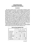
RE
O
F
BE
NS KIT
O
TI ALL
C
T
RU INS
T
S O
IN P T
D
A GU
RE TIN
SE ET
A
S
E
PL
Installation Instructions
Shift Improver Kit
1993 to 2001 GM 4L60E
Part Number 70360
©2006, 2005, 2002 by B&M Racing and Performance Products
Thank you for choosing B&M, The
performance company with over 50
years experience designing and
manufacturing
quality
high
performance automotive driveline
components.
Before proceeding with the
installation please read all of the B&M
4L60E Shift Improver Kit installation
instructions so you will be familiar with
the series of steps required too install
this kit. We have made every effort to
include more than enough information
to assist any-one with minimum
mechanical experience to install this
kit.
The B&M 4L60E Shift Improver Kit
mechanically recalibrates your
transmission to produce firm positive
shifts, this helps reduce clutch pack
heat build up and improves
transmission durability. This kit does
not change or modify shift point RPM
in any range. All transmission shift
point RPM and pressure control
functions remain under full PCM
(Powertrain Control Module) control as
they were originally.
No recalibration kit can fix an
already ailing transmission. If your
4L60E is slipping, overheating, shifting
Printed in the U.S.A.
irregularly or making noise, you should
have it repaired before or, in
conjunction with the installation of your
B&M 4L60E Shift Improver Kit.
General 4L60E Information
B&M’s 4L60E Shift Improver Kit was
designed to provide firm positive shift
quality and improve transmission
durability in original vehicle
installations and those with moderate
engine power improvements. This kit
was not de-signed for and is not
suitable for all out racing applications.
Your 4L60E Transmission is controlled
by the (PCM) which has full control of
the 4L60E’s operation. All of the
parameters that control fluid
pressures, shift point RPM and TCC
(Torque Converter Clutch) Iockup
speed have been preprogramed into
the PCM at the factory. We
have designed this kit as an easy way
to overcome the less desirable
features of the factory calibrated
imperceptible shifts. With this kit you
can set the shifting characteristics of
your 4L60E to one of two levels of
performance, Heavy Duty or Street.
Heavy Duty level produces a solid,
noticeably firm shift when compared
1
to the stock shift feel. While Street
level produces a slightly quicker and
more aggressive shift compared to
Heavy Duty level. After installing the
B&M Shift Improver Kit the actual shift
feel you get will depend on the factory
PCM calibration, Automatic
Transmission Fluid (ATF) temperature
and the type of ATF you have used.
As ATF temperature increases it
becomes thinner (less viscous) which
allows the fluid to flow faster through
small orifices thereby producing faster
shift rates. In addition to the effects of
temperature, each type of ATF (B&M
Synthetic Trick Shift, Dexron III,
Mercon etc.) has a specific
characteristic friction property. This
characteristic friction property is one
of the variables that determines shift
feel and clutch torque capacity.
Dexron/Mercon type ATF’s were
formulated to produce smooth
imperceptible shifts. Both Mercon/
Dexcron III and B&M Synthetic
Trick Shift ATF’s are suitable for use
in your 4L60E transmission. For
Maximum performance and positive
shift feel we recommend B&M
Synthetic Trick Shift ATF.
9500583-04
Special Instructions
Metric tools are required to
disassemble and assemble the
4L60E, see tool list at rear of this
booklet. Choose a clean, dirt and dust
free place to work on your 4L60E. Dirt,
loose threads from rags and pieces of
old gaskets can become lodged in
valve bores and/or separator plate
orifices and cause the transmission
to malfunction. If you do not have a
solvent cleaning setup available, get
several cans of WD40 to clean your
parts.
Warning: Almost all cleaning solvents
pose a threat of fumes and or fire.
Make sure to use cleaning solvents
only in a well ventilated location away
from any source of ignition such as
open flames, sparks, hot water
heaters, etc.
Be careful with the internal and
external wiring harness. Wiring and/
or connectors are easily damaged and
difficult to troubleshoot if they are
damaged.
VERY IMPORTANT
Use petroleum jelly to hold checkballs
and gaskets in place during
installation. DO NOT use any kind of
wheel bearing grease to hold
checkballs in place, these greases do
not melt or mix readily with ATF and
can block shift and pressure conrol
solenoid feed circuit filters and orifices.
Causing erratic shifts and potentially
serious transmission damage
because of low line pressure.
determine the source of the
malfunction(s) that cause(d) any DTC
codes to be set and the required
remedy. Make sure your engine is in
good tune and any problems related
to set trouble codes are repaired
BEFORE attempting to install your
B&M Shift Improver Kit.
Do Not attempt to jumper the Data
Link connector to read a DTC from the
PCM in 1993 / 1995 vehicles until you
have checked your owners manual, or
GM service manual, or verified with
your GM dealer that the particular
PCM in your vehicle allows jumpering
the data link. Jumpering the data link
connector to read DTC’s is not
possible on any 1996 or later OBD II
vehicle and can damage the PCM and
result in a very expensive repair bill.
Except for some 1993 to 1995 PCM’s
all others will require the use of a
diagnostic scanner to read. Some
DTC codes are “hard codes” and may
require a diagnostic scanner to turn
them off after the malfunction, which
set the DTC, has been repaired.
If electrical power to the transmission
is cut or the PCM fails the 4L60E will
operate in “limp home” mode, if this
happens, you will only have Reverse
and Drive 2 range availble.
TRANSMISSION OIL COOLER. We
feel that it is very important that every
vehicle used in heavy duty or high
performance application should have
an auxiliary oil cooler. Excessive heat
is the primary cause of transmission
failures, an and auxiliary oil cooler is
an inexpensive safeguard against
overheating and failure. B&M offers a
wide range of transmission coolers to
suit every need and are available at
your B&M dealer.
DRAIN PLUG KIT 80250. 4L60E
transmission oil pans do not come
from the factory equipped with drain
plugs. The B&M Drain plug kit is
inexpensive and easy to install. It
eliminates the mess when changing
fluid or on pan removal.
TEMPERATURE GAUGE KIT 80212.
Most transmission and converter
failures can be traced directly to
excessive heat. The B&M
transmission temperature gauge can
save you a costly repair bill by warning
you of an overheated transmission.
The B&M temperature gauge comes
with all necessary hardware and is
easy to install.
Preparation
Automatic transmissions operate at
temperatures in the range of 150 and
250 Fahrenheit. We recommend the
vehicle be allowed to cool for
several hours before disassembly to
avoid burns from hot oil and parts.
Cautions about PCM.
The MIL (Malfunction Indicator Light
or Check Engine Light) may be
illuminated (turned ON) if the vehicle
is started and any of the transmission
electrical
connectors
are
disconnected or has wires that are
broken or, have been pinched and/or
shorted. The MIL is programmed to
illuminate whenever a system (engine
or transmission) component
malfunctions and at the same time a
DTC (Diagnostic Trouble Code) is set
in the PCM. You may have to refer to
your owners manual, a GM service
manual or visit a GM dealer to
Transmission ID Pad
4 JY D XXXX
Year Model Model designator D=4L60E
2
f
F
F
A
C
Oil filter seal
bore
D
D
B
C
C
TCC
solenoid
C
C
C
C
D
X
D
X
A
A
G
D
B
Separator plate
support plate
C
A
B
G
E
E
Keep servo vent hole clear.
Avoid using sealer on pan gasket
A
B
1-2 accumulator housing
C
C
E
E
Not all valve bodies will look exactly like the one
show above
D
E
F
G
VALVE BODY FASTENERS
ID
Metric sixe Inch Length Qty
A M6 X 1.0 X 65
2.56
(4)
B M6 X 1.0 X 54.5 2.14”
(3 )
C M5 X 1.0 X 47.5 1.87”
(9)
D M6 X 1.0 X 18.0 0.71”
(5)
E M6 X 1.0 X 35.0 1.38”
(4)
F M8 X 1.25 X 20.0 0.79”
(1)
G M6 X 1,0 X 12.0 0.47”
(2)
3
The vehicle should be raised so
there is at least 2 feet ground
clearance for ease of installation
and safety.
MAKE SURE THE VEHICLE IS
RIGIDLY
AND
SECURELY
SUP-PORTED, JACK STANDS,
WHEEL RAMPS OR A HOIST
WORK BEST, DO NOT USE JACKS
ALONE.
Have an oil drain pan ready to
catch oil and a tray on which to put
small parts so they won’t get lost.
It can never be said enough: Make
sure you have a clean, dust free place
to work. Burrs and dirt are the number
one enemies of an automatic
transmission. Contamination in the
valve body or pressure regulator valve
train can result in serious
transmission damage and/or
unpredictable operation. Transmission
components are precision fit, work
slowly and do not force any parts.
This kit contains all parts necessary
to obtain two different shift feel levels
of performance depending on the
intended use:
1. Heavy Duty level; Towing, campers
and, 4-wheel drive vehicles. Shift feel
is firm and positive.
2. Street level; Dual purpose
performance vehicles, street and strip
performance cars. Street level
produces the firmest shift feel.
Disassembly
STEP 1. Position your drain pan under
the transmission to catch ATF.
Remove oil pan by first removing rear
pan bolts, then work towards the front.
Loosen but do not remove the three
front bolts. If the pan sticks to the
gasket, insert a flat screwdriver
between the pan and case and pry
down gently to break pan loose. Now
slowly back out the front three bolts
to permit draining the ATF. Remove
pan gasket material from pan and case
flanges.
STEP 2. Remove oil filter from case
by gently pulling it straight down. If
filter is clogged or if transmission has
over 50,000 miles on it, the filter and
filter seal should be replaced.
STEP 3. There are several different
wiring harness configurations used on
the 4L60E. Before proceeding further,
make a sketch and some notes
describing your particular unit,
re-cording which connectors go to
which solenoid (See Fig. 2). Notice
how the connectors and wires are
color coded. Remove connectors from
pressure switch assembly and
solenoids then tie the wires up out of
the way.
STEP 4. Remove all except the center
valve body bolt and the 2 pressure
switch bolts marked X (See Fig. 2) If
you do remove all five bolts from the
pressure switch, be sure to recover
all 5 switch assembly O-ring seals as
it is removed. Hold the valve body
firmly with one hand and remove the
remaining bolt slowly. Notice how the
Manual Valve Link is engaged to the
Manual Valve as you remove the valve
body from case. There are seven
check balls in the valve body along
with several pints of oil. Have your
drain pan ready to catch the oil and
check balls (should they fall out). Save
all the check balls in a secure place
where they won’t get lost.
STEP 5. Remove the separator plate
support plate. Remove the 1-2
accumulator housing while holding the
separator plate up to the case. Then
slowly lower the separator plate and
retrieve the check ball located above
the plate. Important: Make a note of
the color and location of the 1-2 and
2-3 accumulator springs for correct
reassembly (See Fig’s. 7-10 ).
Remove all old gasket material from
separator plate, valve body and case
surfaces.
4
STEP 6. Remove pin from 3-4
accumulator piston in case. Remove
3-4 accumulator piston from case
bore. Remove 1-2 accumulator piston
from 1-2 accumulator housing. Be
careful not to damage piston seals or
scratch piston bores while removing
pistons.
Pressure Regulator
STEP 7. Heavy Duty and Street;
Remove the snap ring at the end of
the pressure regulator bore (See Fig.
3). Use a screwdriver to push against
the spring loaded Boost Valve sleeve
while removing the retaining ring.
Remove Boost Valve Sleeve and Valve
and the Pressure Regulator Spring.
The Pressure Regulator Valve may fall
out but it does not have to be removed.
Reassemble the pressure regulator
assembly as shown (See Fig. 4) using
the GREEN Pressure Regulator Spring
from the kit. Use the new retaining ring
included with kit. Important: Make sure
the retaining ring is fully seated in its
groove when assembled. If the
retaining ring is not fully seated in its
groove, the pressure regulator
assembly will blow out of its bore
resulting in NO LINE pressure.
Modifications
STEP 8. Carefully remove the snap-in
solenoid oil filters from the separator
plate. Using the supplied drills, enlarge
the holes in your separator plate as
shown in (Fig. 5). Before drilling, mark
the hole locations and drill size on the
separator plate and double check
them
against the illustration. Make sure to
use the correct drill size specified for
‘V’ cut in it goes next to the valve body
(See Fig. 11). If your gaskets become
damaged anytime during the
installation of the kit, replace them. If
you can-not obtain B&M replacement
gaskets then purchase OEM gaskets
for your specific year and model
vehicle.
STEP 12. Heavy Duty Level Only; (See
Figures 7 or 9) Place the 3-4
Accumulator Pin in the case. Over the
pin place the Spacer, 3-4 Accumulator
Piston and Stock Spring (spring is
installed at step 14). Remove the
spring and piston from the 1-2
Accumulator Housing. Over the pin
Install the spacer, piston (notice
Figure 4
the performance level (Heavy Duty or
Street). Remove burrs and clean the
separator plate after drilling holes.
STEP 9. Install Aluminum Plug in
Separator plate (See Fig. 6). With Plug
installed in hole, hold Separator plate
parallel to anvil and strike plug squarely
with a hammer. Peen plug just enough
so it is snug in the hole and will not
fall out easily.
Reassembly
STEP 10. Place check balls in valve
body and case (See Fig. 12) in the
positions shown. Use a dab of
petroleum jelly to hold check balls in
position. Double check the checkball
placement against the provided
diagram to prevent misplacement.
Improper checkball placement can
result in severe transmission damage.
STEP 11. Snap new solenoid filters
into separator plate (See Fig. 5). Make
sure filters are on the correct side of
separator plate, Place each new
separator plate gasket on the
separator plate and check to make
sure no holes in the separator plate
are covered by the gasket. Use
petroleum jelly to stick gaskets to
separator plate during installation. The
gasket with the ‘C’ cut in it goes next
to the case and the gasket with the
5
orientation) and spring. Use
petroleum jelly to hold components in
place. Proceed to step 14.
STEP 13. Street Level Only; (See
Figures 8 or 10) Place the 3-4
Accumulator Pin in the case. Over the
pin place the spacer and 3-4
Accumulator Piston, using petroleum
jelly to hold them in place. Remove
the spring and piston from the 1-2
Accumulator Housing. Install both
spacers over the pin, then the piston
(notice orientation). No 1-2 or 3-4
accumulator springs are used for
Street level shift performance.
STEP 14. Make sure the 2-4 Band
Anchor has not fallen out (See Fig.
12). With the 3-4 Accumulator
components and the case check ball
in place, Place the Separator Plate
and gasket assembly up to the case
followed by the 1-2 Accumulator
Housing assembly. Carefully line up
the gaskets and install accumulator
housing and support plate. Tighten
bolts finger tight ONLY (See Fig. 2).
STEP 15. Make sure Valve Body
check balls are in correct locations
(See Fig. 12). Position the manual
valve so the manual valve link can be
engaged (See Fig. 4). The manual
valve link must be placed into the hole
in the manual valve at a right angle to
valve axis, then rotated 90 degrees to
allow the valve to enter the manual
valve bore. Do not force valve or link
at any time. When the valve is fully
engaged, align the valve body and case
holes and install one bolt finger tight
to hold valve body in place. Refer to
your sketch and notes to properly
position wire harness clips and
solenoid connectors. Install all of the
remaining bolts finger tight to finish
lining up the separator plate and
gaskets (See Fig. 2). Tighten all the
valve body, accumulator and support
plate bolts to 11 Nm (8 Lb. Ft.). Avoid
striped threads. Do not over tighten
bolts.
STEP 16. Double check your
installation;
1: make sure all bolts are installed
and torqued.
2: Wiring harness is properly
connected.
3: Regulator valve retaining ring fully
seated in groove. Coat the filter pickup
tube with clean ATF then push the filter
tube into the pump bore until it is fully
seated.
STEP 17. Remove any old pan gasket
material from pan and case pan rail.
Clean inside of pan with solvent. You
may want to install a B&M Drain plug
kit (80250) at this time. Install the new
Pan Gasket on the pan and align the
holes. Use petroleum jelly to help hold
the gasket in place during installation
of pan. Do not use any gasket sealer
or silicone compounds. To prevent
premature band failure make sure the
vent hole shown in Fig. 2 is not blocked
or obstructed. Place pan up to case,
6
1994 to 02
1994 to 01
1994 to 02
1994 to 01
align holes and install all bolts finger
tight. Tighten bolts to 12 NM (9 Lb.
Ft.). Do not over tighten bolts. If the
bolts are over tightened the gasket will
deform excessively and result in oil
leaks.
STEP 18. Fill transmission with ATF
to the full mark on dip stick. You will
need about 4 to 6 quarts. We
recommend B&M Synthetic Trick
Shift ATF for Heavy Duty and Street
level applications. With vehicle still off
the ground, start the engine and shift
transmission through all gears.
Check for leaks around oil pan flange
and drain plug. Place selector in
neutral and check the fluid level. Stop
engine and then lower vehicle.
STEP 19. Test drive vehicle and
re-check for leaks while transmission
7
is hot. Check fluid level again,
adjusting level as required.
ERROR CONDITION WHERE TO LOOK FOR CAUSE
High or Low Oil Pressure Oil Pump
~ Pressure Regulator Valve Stuck.
~ P/R Retainnig Ring not fully seated in groove
~ Orifice hole in P/R Boost Valve sleeve plugged.
Oil Filter
~ Cracks in Filter Intake Tube.
~ Intake Tube Seal Damaged.
~ Wrong grease used on reassembly (clogging filter).
Valve Body Assembly ~ Spacer Plate or Gaskets misassembled or damaged.
~ Check Balls omitted or mislocated.
~ Wrong grease used on reassembly (clogging Solenoid
Filter.)
Harsh Shifts
Valve Body Assembly ~ Wrong holes drilled.
~ Separator Plate or gaskets misassembled or damaged.
~ Check Balls omitted or mislocated.
Inconsistent Shift Points Valve Body Assembly ~ Separator Plate or gaskets misassembled or damaged.
External Linkage
~ Manual Shift Lever Linkage misadjusted.
No or Slips in 1st Gear
1-2 Accumulator
~ Damaged or missing piston seal.
~ Incorrect spacer(s) holding piston above case surface.
Low Oil Pressure
~ (See above)
Valve Body Assembly ~ Spacer Plate or gaskets misassembled or damaged.
~ Check Balls omitted or mislocated,
~ Solenoid disconnected or damaged,
~ 2-4 Band Anchor missing
No or Slipping 2-3 Shift Valve Body Assembly ~ Spacer Plate or gaskets misassembled or damaged.
~ Solenoid disconnected or damaged.
~ Spacer Plate or gaskets misassembled or damaged.
No or Slipping 3-4 Shift Valve Body Assembly ~ Spacer Plate or gaskets misassembled or damaged.
~ Solenoid disconnected or damaged.
~ Spacer Plate or gaskets misassembled or damaged.
3-4 Accumulator
~ Damaged or missing piston seal,
No or Slipping Reverse
Valve Body Assembly ~ Spacer Plate or gaskets misassembled or damaged.
Oil Pump
~ P/R Retaining Ring not fully seated in groove.
No TCC Apply
TCC Solenoid
~ Solenoid disconnected or wiring damaged.
PARTS LIST
TOOL LIST
1
1
1
1
1
1
1
1
1
1
1
1
1
B&M TRANSMISSION
3/8" drive ratchet wrench
3/8" torque wrench
2"-6" 3/8" drive extension
8, 10, 13mm Sockets
8, 10, 13mm combination wrench
8" Plain Screwdriver
Small Internal Retaining Ring Pliers
Needle nose pliers
Hammer
Gasket scraper
3/8" Drill motor
Fine cut fiat file
Wet or Dry sand paper
1
1
1
2
1
1
1
1
1
1
1
1
1
1
Pan Gasket
Upper Valve Body Gasket
Lower Valve Body Gasket
Snap in Solenoid Filters Aluminum Plug
GREEN Press Regulator Spring
Press Regulator Retaining Ring
3/8"x 5/16" ID RED Spacer
1/2"L x 5/16" ID GREEN Spacer
5/8"L x 5/16" ID YELLOW Spacer
3/4"L x 5/16" ID BLUE Spacer
19/32"L x 1/4" ID VIOLET Spacer
3/8"L x 1/4" ID WHITE Spacer
3/32" (.094) Drill 1/8" (.125) Drill
1/2" x 1" x 2" Anvil Plate
TRANSMISSION AND DRIVETRAIN