1
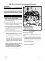
11. Unthread rubber boot from odometer reset switch and
while carefully removing left side instrument nacelle from
motorcycle, pull odometer reset switch from hole.
12. Gently bend back molded retainer to release switch
bracket assembly from instrument nacelle.
NOTE
If installing both a left (LH) nacelle half and a right (RH)
nacelle half refer to the Service Manual for nacelle removal
and replacement procedures.
Install Nacelle
13. Obtain replacement nacelle half (LH) from kit and the
plug (Part No. 789) for the clutch cable clip hole or the
clutch cable clip (Part No. 70385-01) and the plug (Part
No. 728) for the odometer reset switch hole.
14. Determine whether to install the odometer reset switch
in the either the right front nacelle half or the left nacelle
switch panel. If necessary, use a circular file to ream the
unused hole and precisely fit the plug (Part No. 728) to
the unused hole.
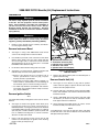
15. Snap switch bracket and switch assembly into molded
retainer in nacelle.
16. Carefully fit left nacelle half to right. If using right front
odometer reset hole, route switch and wiring and install
rubber boot
17. If using left nacelle switch panel hole, route switch and
wiring under the left side of the switch bracket and slide
odometer reset switch through hole while carefully
placing the nacelle half in place. Install rubber boot.
18. Verify that left nacelle half is aligned to right. Four pins
on the left side of the nacelle must fully engage holes on
right.
19. Using a T40 TORX drive head, install two bolts (with flat
washers) to fasten left nacelle half to upper and lower
fork brackets. Be sure to capture clutch cable clip when
installing upper bolt. Alternately tighten bolts to 15-20 ftlbs (20-27 Nm).
20 Determine whether to install the clutch cable clip (Part
No. 70385-01) or the plug (Part No. 789) to fill the hole.
If necessary, use a circular file to ream the clutch cable
hole in the nacelle to precisely fit the plug.
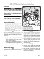
Install Ignition Switch
21. Install switch position plate onto threaded post of ignition
switch housing. Tabs on plate fit in holes at top of
nacelle halves.
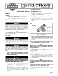
22. See Figure 2. Slide spacer (5) over threaded post of
ignition switch housing until it contacts switch position
plate. Slide collar (4) over post with tab side down (and
forward) (6). Install nut (3), and using a 7/8 inch wrench
on flats, tighten to 50-70 in-lbs (5.7-7.9 Nm).
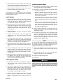
Install Instrument Bezel
24. Route speaker switch wiring and mate speaker switch
connector [105] halves (4-place Multilock).
25. See Figure 6. Connect instruments and indicator lamps
to in interconnect harness:
a. Position Indicator lamps connector [21], 10-place
Multilock, between speedometer and tachometer
brackets and secure using new cable strap. Cut any
excess cable strap material.
b. Install speedometer connector {39}, 12-place
Packard, at back of speedometer until clear plastic
latch on secondary lock “clicks” into the locked position.
c. Take note of the offset terminal when mating pin and
socket halves of tachometer connector [108], 12place Packard. Using thumbs of both hands, push on
each side of connector until tight. Connector is a friction fit with no external latches.
26. Verify that left and right sides of instrument nacelle are
properly mated. Pins on left half of nacelle must fully
engage holes on right.
27. Insert tab at rear of bezel into slot of instrument nacelle
(just in front of ignition switch). Holding left and right
sides of nacelle together, place bezel over instrument
nacelle flange. When properly mated, tabs at front
instrument nacelle engage lip in slit at front of bezel
(behind decorative adhesive strip).
NOTE
If tabs do not properly engage slot at front of bezel, then a
loose fit will result. Remove decorative adhesive strip by gently prying up outer edges, and using a flat bladed screw driver, carefully raise tabs so that they engage lip in slot. If
damaged, install new decorative adhesive strip.
28. Using a T25 TORX drive head, install screw on each
side of bezel. Tighten screws to 25-35 in-lbs (2.8-4.0
Nm).
29. Move handlebars stop to stop in left and right directions
making sure movement is free (not binding).
30. Reconnect negative battery cable.
31. Install seat.
1WARNING
Pull up on seat to verify that it is properly secured, front
and rear. A loose seat may shift during vehicle operation
and startle the rider, possible causing loss of vehicle
control, which could result in death or serious injury.
(0007a)
23. With the red arrow pointing toward the ACCESS
position, install the ignition switch knob. Turn key
clockwise to UNLOCK position and then turn knob to
OFF.
-J01793
7 of 9