1
OKIPAGE 14i
LED Page Printer
SERVICE
MANUAL
Table of Contents
Page
Service Manual for OKIPAGE 14i
0 Introduction
Introduction
1 Specifications
1.1 System Configuration
1.2 Printer Configuration
1.3 Optional Configuration
1.4 Specification
1.5 Safety Standards
....1.5.1 Certification Label
....1.5.2 Warning Label
....1.5.3 Warning/Caution Marking
2 Operation
Operation Description
2.1 Main Control Board
2.2 Power Supply/Sensor Board
2.3 Electrophotographic Process
....2.3.1 Electrophotographic Process Mechanism
....2.3.2 Electrophotographic Process
....2.3.3 Process Operation Descriptions
....2.3.4 Revision of LED Head Illumination
2.4 Paper Jam Detection
2.5 Cover Open
2.6 Toner Low Detection
3 Disassembly
3.1 Precautions for Parts Replacement
3.2 Parts Layout - [Lower base unit]
........[Upper cover unit]
........[Base unit]
3.3 How to Change Parts
....3.3.1 Upper Cover Assy
....3.3.2 LED Head
....3.3.3 Operator Panel Assy
....3.3.4 Lower Base Unit
....3.3.5 Pulse Motor Main/Drum
....3.3.6 Pulse Motor (Registration)
1
2
3
4
5
6
7
8
9
10
11
12
13
14
15
16
17
18
19
20
21
22
23
24
25
26
28
29
30
31
32
Table of Contents
....3.3.7 Face Up Stacker Assy
....3.3.8 Eject Roller Assy
....3.3.9 Motor Assy
....3.3.10 Hopping Roller Shaft Assy
....3.3.11 Stacker Cover Assy
....3.3.12 Registration Roller
....3.3.13 Roller Transfer Assy
....3.3.14 Fusing Unit
....3.3.15 Back-up Roller
....3.3.16 Sensor Plate (Inlet)
....3.3.17 Sensor Plate (Outlet), Sensor Wire Assy
....3.3.18 Manual Feed Guide Assy
....3.3.19 Sensor Plate (Paper Supply)
....3.3.20 Main Control M7E-PCB
....3.3.21 Power Supply/Sensor Board, High Voltage Unit and
Contact Assy
....3.3.22 Cassette Guide L Assy
....3.3.23 Cassette Guide R Assy
....3.3.24 Spacer Bearing (L/R)
4 Adjustments
4. Adjustment
....4.1 Maintenance Modes and Functions
........4.1.1 User Maintenance Mode
........4.1.2 System Maintenance Mode
........4.1.3 Engine Maintenance Mode
........4.1.4 EEPROM Initialization
....4.2 Adjustment When Replacing a Part
........4.2.1 Uploading/Downloading EEPROM data
5 Maintenance
5.1 Periodical Replacement Parts
5.2 Cleaning
....5.2.1 Cleaning of LED Lens Array
....5.2.2 Cleaning Page Function
6 Troubleshooting
6.1 Troubleshooting Tips
6.2 Points to Check before Correcting Image Problems
Page
33
34
35
36
37
38
39
40
41
42
43
44
45
46
47
49
50
51
52
53
54
55
56
57
58
60
61
62
63
64
65
66
Table of Contents
6.3 Tips for Correcting Image Problems
6.4 Preparation for Troubleshooting
6.5 Troubleshooting Flow
....6.5.1 LCD Status Message/Problem List
....6.5.2 LCD Message Troubleshooting
........(1) The printer does not work normally after the power is
turned on.
........(2) [JAM error]
............Paper input jam
............Paper feed jam
............Paper exit jam
........(3) Paper size error
........(4) Fusing unit error (ERROR 71) (ERROR 72) (ERROR
73)
........(5) SSIO error (ERROR 74)
........(6) Fan error (ERROR 70)
....6.5.3 Image Troubleshooting
........(1) Images are light or blurred entirely
........(2) Dark background density
........(3) Blank paper is output
........(4) Black vertical belts or stripes
........(5) Cyclical defect
........(6) Prints voids
........(7) Poor fusing
........(8) White Vertical belts or streaks
........Figure 6-4
........Figure 6-5
7 Wiring Diagram
7.1 Interconnect Signal Diagram
7.2 PCB Layout and Connector Signal List
7.3 Resistance Check
8 Parts List
Lower Base Unit
Upper Cover Unit
Base Unit
A Centronics Parallel Interface
Page
67
68
69
70
71
72
73
74
75
76
77
78
79
80
81
82
83
84
85
86
87
88
89
90
91
92
93
94
96
97
98
Table of Contents
Centronics Parallel Interface
B Universal Serial Bus (USB)
Universal Serial Bus (USB)
C Loop Test (RS-232C Interface)
Loop Test (RS-232C Interface)
D Diagnostics Test
1. Maintenance Modes
....1.1 User Maintenance Mode
....1.2 System Maintenance Mode
....1.3 Engine Maintenance Mode
....1.4 User Factory Set Operation
Product Accessory 1: RS-232C Serial Interface (Option)
RS-232C Serial Interface (Option)
Product Accessory 2: Multi-Purpose Feeder Maintenance
1. PREFACE
....1.1 Functions
....1.2 External View and Component Names
2. MECHANISM DESCRIPTION - General Mechanism
....2.2 Hopper Mechanism
3. PARTS REPLACEMENT
....3.1 Precautions Concerning Parts Replacement
....3.2 Parts Layout
....3.3 Parts Replacement Methods
........3.3.1 Link
........3.3.2 Separator
........3.3.3 OLEV-11 PCB
........3.3.4 Pulse Motor
........3.3.5 Planet Gear
........3.3.6 Roller-A and B
4. TROUBLESHOOTING - Precautions Prior to the
Troubleshooting
....4.1 Precautions Prior to the Troubleshooting
....4.2 Preparations for the Troubleshooting
....4.3 Troubleshooting Method
........4.3.1 LCD Status Message List
5. CONNECTION DIAGRAM
Page
99
100
101
102
103
104
105
106
107
108
109
110
111
112
113
114
115
116
117
118
119
120
121
122
122
123
124
125
126
Table of Contents
....5.1 Interconnection Diagram
....5.2 PCB Layout
6. PARTS LIST
Product Accessory 3: High Capacity 2nd Paper Feeder
High Capacity Second Paper Feeder Maintenance
1. OUTLINE
....1.1 Functions
....1.2 External View and Component Names
2. MECHANISM DESCRIPTION - General Mechanism
....2.1 General Mechanism
....2.2 Hopper Mechanism
3. PARTS REPLACEMENT
....3.1 Precautions Concerning Parts Replacement
....3.2 Parts Layout
....3.3 Parts Replacement Methods
........3.3.1 Stepping Motor (Hopping)
........3.3.2 TQSB-2 PCB
........3.3.3 Hopping Roller Shaft Assembly and One-way Clutch
Gear
4. TROUBLESHOOTING - Precautions Prior to the
Troubleshooting
....4.1 Precautions Prior to the Troubleshooting
....4.2 Preparations for the Troubleshooting
....4.3 Troubleshooting Method
........4.3.1 LCD Status Message List
5. CONNECTION DIAGRAM
....5.1 Interconnection Diagram
....5.2 PCB Layout
6. PARTS LIST
....High Capacity Second Paper Feeder
....SECTION 1 CABINET & CASSETTE ASSEMBLY
....SECTION 2 MECHANICAL ASSEMBLY
....2nd Tray Parts List
Product Accessory 4: Network Interface (option)
Network Interface (option)
....1) Connector
Page
126
127
128
129
130
130
131
132
132
133
134
135
136
137
138
139
140
141
141
142
143
144
145
146
147
148
148
150
151
152
Table of Contents
....2) Cable
....3) Signal
....4) Appearance
....5) Physical dimensions
....6) List of protocols
....7) TCP/IP
....8) Netware
....9) EtherTalk
....10) NetBEUI
....11) OKI Original Port
....12) Others
....13) Setup
....14) TROUBLESHOOTING
Page
Service Manual for OKIPAGE 14i
Page: 2
Chapter 0 Introduction
Introduction
This Service Handbook describes the field maintenance methods for OKIPAGE 14i Digital LED Printer. This manual is written for use by the maintenance
personnel. Please note that you should refer to the Printer Handbook and Printer Setup for the handling and operating methods of the equipment.
Copyright 2000, Oki Data, Division of OKI America, Inc. All rights reserved. See the Oki Data Business Partner Exchange
(BPX) for any updates to this material. (http://bpx.okidata.com)
Service Manual for OKIPAGE 14i
Chapter 1 Specifications
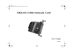
1.1 System Configuration
OKIPAGE 14i consists of control and engine blocks in the standard configuration, as shown in Figure 1-1.
In addition, the options marked with asterisk (*) are available.
Page: 3
Figure 1-1
Copyright 2000, Oki Data, Division of OKI America, Inc. All rights reserved. See the Oki Data Business Partner Exchange
(BPX) for any updates to this material. (http://bpx.okidata.com)
Service Manual for OKIPAGE 14i
Chapter 1 Specifications
1.2 Printer Configuration
The printer unit consists of the following hardware components:
l
Electrophotographic Processor
l
Paper Feeder
l
Controller
l
Operator Panel
l
Power Supply Unit
The printer unit configuration is shown in Figure 1-2.
Page: 4
Copyright 2000, Oki Data, Division of OKI America, Inc. All rights reserved. See the Oki Data Business Partner Exchange
(BPX) for any updates to this material. (http://bpx.okidata.com)
Service Manual for OKIPAGE 14i
Page: 5
Chapter 1 Specifications
1.3 Optional Configuration
The options shown below are available for use with OKIPAGE 14i. These are available separately from the printer unit.
(1) High Capacity Second Paper Feeder
(2) Multi-Purpose Feeder
(3) Expansion Board
(4) RS-232C Serial Interface Board
(5) Network Interface Board (10 Base)
(6) Network Interface Board (10/100 Base)
(7) DRAM SIMM Memory
DRAM SIMM memory is available with memory of 1 MB (min.) to 32 MB (max.). The access time of SIMM memories are 60ns, 70ns, 80ns, and 100ns.
(8) Flash memory SIMM
Copyright 2000, Oki Data, Division of OKI America, Inc. All rights reserved. See the Oki Data Business Partner Exchange
(BPX) for any updates to this material. (http://bpx.okidata.com)
Service Manual for OKIPAGE 14i
Chapter 1 Specifications
1.4 Specification
(1)
Type:
Desktop
(2)
Outside dimensions
Height: 8.5" (215 mm)
Width 13.6" (345 mm)
Depth 15.7" (400mm)
(3)
Weight
19.8 lbs.
(4)
Development
method
Exposure method
Paper used
Dry electrophotography LED stationary head
(5)
<Type>
Standard paper
- Xerox 4200 (20 lbs)
l Application paper (manual face-up feed)
- Label
- Envelope
- OHP paper (Transparency)
l
l
l
<Size>
Standard
Letter
Legal * [*Without Mutli-Purpose Feeder (Option)]
Legal-13*
Executive
-COM-10** [**manual feed and Multi-Purpose Feeder
(Option) only]
Monarch**
DL**
C5**
B5 (JIS)
A6
Applicable sizes
Page: 6
- Width: 3.4" x 8.5" (86 to 216 mm)
- Length: 5.5" to 14" (140 to 355.6 mm)
<Thickness>
2
- Automatic feed: 16 to 28 lbs (60 to 135 g/m )
- Manual feed: Label, OHP paper (transparency), Envelope
(24 to 28 lbs.)
(6)
Printing speed:
First print: 14 seconds typical for the Letter size paper.
[Except Multi-Purpose Feeder (11ppm)]
o
Warm-up time: 45 seconds typical at room temperature [68
o
F (20 C), AC 120/230 V].(120 VAC for ODA, 230 VAC for
OEL/INT)
First page print time: 7.5 seconds typical for the Letter size
paper after warm-up.
(7)
Automatic paper feed or manual paper feed
(9)
Paper feeding
method
Paper delivery
method
Resolution
(10)
Power input
120 VAC + 5.5%, -15%
230 VAC +/- 10%
(11)
Power consumption
Peak: Approx. 600W
Typical operation: Approx. 340W
Idle: Approx. 75W
Power save mode: Approx. 10W
(12)
Temperature and
humidity
(8)
Temperature
Humidity
Maximum wet bulb
Face down/face up
600 dpi x 600 dpi (true)
600 x 1200 dots/inch graphics
In operation
50-90
(10-32)
Power off mode
32-110
(0-43)
During Storage
14-110
(-10-43)
20-80
77
10-90
80.4
10-90
-----
Unit
o
F
o
C
%RH
o
temperature
(25)
(26.8)
Minimum
difference between
wet and dry bulb
temperatures
35.6
(2)
35.6
(2)
F
C
o
F
o
C
o
-----
1. Storage conditions specified above apply to printers in packed condition.
2. Temperature and humidity must be in the range where no condensation occurs.
(13)
Noise
During operation: 53 dB (A) or less
Standby: 38 dB (A) or less
Quite mode: Back ground level
(14)
Consumables
Toner cartridge kit - 2,000 (Type 5) (5% duty)
Toner cartridge option - 4,000 (Type 8) (5% duty)
Image drum cartridge - 20,000 (at continuous printing);
14,000
(3 page/job) without Power Save
Copyright 2000, Oki Data, Division of OKI America, Inc. All rights reserved. See the Oki Data Business Partner Exchange
(BPX) for any updates to this material. (http://bpx.okidata.com)
Service Manual for OKIPAGE 14i
Page: 7
Chapter 1 Specifications
1.5 Safety Standards
1.5.1 Certification Label
1.5.2 Warning Label
1.5.3 Warning/Caution Marking
Copyright 2000, Oki Data, Division of OKI America, Inc. All rights reserved. See the Oki Data Business Partner Exchange
(BPX) for any updates to this material. (http://bpx.okidata.com)
Service Manual for OKIPAGE 14i
Page: 8
Chapter 1 Specifications
1.5.1 Certification Label
The safety certification label is affixed to the printer in the position described below.
Copyright 2000, Oki Data, Division of OKI America, Inc. All rights reserved. See the Oki Data Business Partner Exchange
(BPX) for any updates to this material. (http://bpx.okidata.com)
Service Manual for OKIPAGE 14i
Page: 9
Chapter 1 Specifications
1.5.2 Warning Label
The warning labels are affixed to the sections which may cause bodily injury.
Follow the instructions on warning labels during maintenance.
Copyright 2000, Oki Data, Division of OKI America, Inc. All rights reserved. See the Oki Data Business Partner Exchange
(BPX) for any updates to this material. (http://bpx.okidata.com)
Service Manual for OKIPAGE 14i
Chapter 1 Specifications
1.5.3 Warning/Caution Marking
The following warning and caution markings are made on the power supply/sensor board.
Page: 10
* No fuse is mounted here for 200V series.
ENGLISH - Heatsink and transformer core present risk of electric shock. Test before touching.
FRENCH - Le dissipateur thermique et le noyau du transformateur présentent des risques de choc électrique. Testez avant de manipuler.
SPANISH - Las disipadores de color el núcel del transformador pueden producir un choque eléctrico. Compruebe antes de tocar.
PORTUGUESE - O dissipador de calor e o núcleo do fransiormador apresentam risco de choque elétrico. Teste antes de focar.
ENGLISH - Circuits maybe live after fuses open.
FRENCH - Il se peut que les circuits soient sous tension une fois que les fusibles ont éfé rerirés.
SPANISH - Las circuitos pueden estar activos una vez que se hayan abierio los fusibles.
PORTUGUESE - Os circuitos podem estar energizados após os fusiveis se queimarem.
Copyright 2000, Oki Data, Division of OKI America, Inc. All rights reserved. See the Oki Data Business Partner Exchange
(BPX) for any updates to this material. (http://bpx.okidata.com)
Service Manual for OKIPAGE 14i
Page: 11
Chapter 2 Operation
Operation Description
OKIPAGE 14i consists of a main control board, a power supply/sensor board, an operator panel, an electrophotographic process mechanism, and revision for
illumination of LED head.
The main control board receives data via the host I/F, it then decodes, edits and stores the data in memory. After completing the editing of a single page of data,
it references the font memory and generates bit image data, which is transferred to the LED head in one dot line units.
Through the electrophotographic process mechanism, the data is printed on the paper.
The operator panel is used for operations and status display.
OKIPAGE 14i block diagram is shown in Figure 2-1.
Copyright 2000, Oki Data, Division of OKI America, Inc. All rights reserved. See the Oki Data Business Partner Exchange
(BPX) for any updates to this material. (http://bpx.okidata.com)
Service Manual for OKIPAGE 14i
Page: 12
Chapter 2 Operation
2.1 Main Control Board
The main control board consists of a single chip CPU, two program/font ROMs, four DRAMs, an EEPROM, a host interface circuit, and a mechanism driving
circuit.
(1) Single chip CPU
The single chip CPU is a custom CPU (32-bit internal bus, 32-bit external bus, 32-bit external bus, 49.766-MHz clock, which incorporates the RISC CPU and its
peripheral devices, and has the following functions:
(2) Program and Font ROMs
Built-in Device
Function
Chip select controller
Bus controller
DRAM controller
DMA controller
Control of ROM, DRAM and I/O device.
Parallel interface controller
Control of Centronics parallel interface.
Serial interface controller
Video output port
LED STB output port
Control of RS-232C serial interface.
Controls LED head.
Timer
Generation of various control timing
Monitoring of paper running and paper size.
Serial I/O port
I/O Port
Control of operator panel, EEPROM, and options.
Input and output of sensor and motor signals.
Transfer of image data from DRAM to video output
port.
The Program and Font ROMs store the equipment program and various types of fonts. Mask ROM is used as Program and Font ROMs. The mounting locations
of these Program and Font ROMs vary depending on the type of the ROMs.
(3) DRAM
The DRAM is a 8MB resident memory on the main control board that stores edited data, image data, DLL data and macro data.
(4) EEPROM
16k-bit Electrically Erasable PROM (EEPROM), is loaded with the following kinds of data:
l
l
l
Menu data
Various counter data (page counter, drum counter)
Adjusting parameters (LED head drive time, print start position, paper feed length)
(5) Parallel Interface
Parallel data is received from a host system via parallel interface which conforms to the IEEE 1284 specification.
(6) USB Interface
Serial data is received from a host system via USB which conforms to the USB 1.1 specification
Copyright 2000, Oki Data, Division of OKI America, Inc. All rights reserved. See the Oki Data Business Partner Exchange
(BPX) for any updates to this material. (http://bpx.okidata.com)
Service Manual for OKIPAGE 14i
Page: 13
Chapter 2 Operation
2.2 Power Supply/Sensor Board
The power supply/sensor board consists of an AC filter circuit, a low voltage power supply circuit, a high voltage power supply circuit, heater drive circuit, and
photosensors.
(1) Low Voltage Power Supply Circuit
This circuit generates the following voltages.
Output voltage
Application
+5 V
Logic circuit supply voltage.
+30 V
Motor and fan drive voltage and source voltage for high-voltage
supply.
Source voltage for high-voltage supply
LED head supply voltage
+ 12 V
+ 3.3 V
(2) High Voltage Power Supply Circuit
This circuit generates the following voltages required for electrophotographic process from +5 V, according to the control sequence from the main control board.
When cover open state is detected, +5 V supply is interrupted automatically to stop the supply of all high-voltage outputs.
Output
Voltage
Application
CH
-1.3 KV
Voltage to be applied to charge roller.
DB
-265 V/+300 V
Voltage to be applied to a developing roller.
SB
-500 V/ 0 V
Voltage to be applied to a sponge roller.
TR
CB
+500 V to +3.5 KV/-1100 V
+400 V/+3.5 KV
Voltage to be applied to a transfer roller. (Variable)
Voltage to be applied to a cleaning roller.
(3) Photosensor
The photosensor mounted on this power supply/sensor board monitors the status of paper being fed through the printer during printing.
The sensor layout diagram is shown in Figure 2-2 below.
Figure 2-2
Sensor
Function
Sensing State
Inlet sensor 1
Detects the leading part of the paper and
gives the monitor timing for switching from
hopping operation to feeding operation.
Monitors paper feeding situation and paper
size based on the paper arrival time and
running time.
Detects the paper width.
ON: Paper exists.
OFF: No paper exists.
Inlet sensor 2
Paper sensor
Detects the leading portion of the paper.
Monitors paper feeding situation.
ON: A4 or larger.
OFF: Smaller than A4.
ON: Paper exists.
OFF: No paper exists.
Output sensor
Monitors paper feeding and size according to
ON: Paper exists.
Paper end sensor
the time of arrival to and leaving past the
sensor.
Detects the end of the paper.
Toner sensor
Detects the lack of toner.
OFF: No paper exists.
ON: Paper exists.
OFF: No paper exists.
-----
Copyright 2000, Oki Data, Division of OKI America, Inc. All rights reserved. See the Oki Data Business Partner Exchange
(BPX) for any updates to this material. (http://bpx.okidata.com)
Service Manual for OKIPAGE 14i
Page: 14
Chapter 2 Operation
2.3 Electrophotographic Process
2.3.1 Electrophotographic Process Mechanism
2.3.2 Electrophotogrpahic Process
2.3.3 Process Operation Descriptions
2.3.4 Revision of LED Head Illumination
Copyright 2000, Oki Data, Division of OKI America, Inc. All rights reserved. See the Oki Data Business Partner Exchange
(BPX) for any updates to this material. (http://bpx.okidata.com)
Service Manual for OKIPAGE 14i
Page: 15
Chapter 2 Operation
2.3.1 Electrophotographic Process Mechanism
This mechanism actuates the printing of image data supplied by the main control board on the paper by electrophotographic process.
The layout of the electrophotographic process mechanism is shown in Figure 2-3.
(1) Image Drum Unit
The image drum unit consists of a sensitive drum, a charger, and a developer. The unit forms a toner image on the sensitive drum, using a electrostatic latent
image formed by the LED head.
(2) Registration Motor
The registration motor is a pulse motor of 48 steps/rotation with two-phase excitement by the signal from the main control board. It drives the hopping and
registration rollers via two one-way clutches according to the direction of rotation.
(3) Main (Drum) Motor
The main or drum motor is a pulse motor of 48 steps/rotation with two-phase excitement by the signal from the main control board and is the main motor of this
mechanism.
(4) LED Head
Image data for each dot line from the main control board is received by the shift register and latch register. The 4992 LED's are driven to radiate the image data
on the image drum.
(5) Fuser
The fuser consists of a heater, a heat roller, a thermistor and a thermostat.
The AC voltage from the power supply/sensor board is applied to the heater controlled by the HEATON signal from the main control board. This AC voltage heats
the heater. The main control board monitors the heat roller temperature via the thermistor, and regulates the heater roller to keep it at a designated temperature
in the menu, depending on the thickness of the paper (tray 1&2: light=165°C, medium light=170°C, medium=175°C, medium heavy and heavy=195°C; manual
feeding and power envelope feeder: light=175°C, medium light=180°C, medium=185°C, medium heavy=190°C, heavy=195°C, transparency = 160°C) by
connecting or disconnecting the AC voltage supply to the heater.
When an abnormal rise of the heater roller temperature takes place, the thermostat of the heater voltage supply circuit becomes active and forcibly cuts the AC
voltage supply.
The temperature setting of the fuser can be changed through operator panel setting.
Copyright 2000, Oki Data, Division of OKI America, Inc. All rights reserved. See the Oki Data Business Partner Exchange
(BPX) for any updates to this material. (http://bpx.okidata.com)
Service Manual for OKIPAGE 14i
Page: 16
Chapter 2 Operation
2.3.2 Electrophotographic Process
The electrophotographic processing is outlined below. The electrophotographic printing process is shown in Figure 2-4 (see below).
1 Charging
The surface of the image drum is charged uniformly with a negative charge by applying the negative voltage to the charge roller.
2 Exposure
Light emitted from the LED head irradiates the negatively charged surface of the image drum. The surface potential of the irradiated portion of the image drum
surface becomes lower, forming the electrostatic latent image associated with the print image.
3 Developing and toner recovery
When the negatively charged toner is brought into contact with the image drum, it is attracted to the electrostatic latent image by static electricity, making the
image visible. At the same time, the residual toner on the image drum is attracted to the developing roller by static electricity.
4 Transfer
When paper is placed over the image drum surface, the positive charge which is opposite in polarity to that of the toner, is applied to the reverse side of the paper
by the transfer roller. The toner is attracted by the positive charge and is transferred onto the paper. This results in the transfer of the toner image formed on the
image drum onto the paper.
5 Temporary cleaning
Residual toner which remains on the image drum without being transferred is evened out by the cleaning roller and is temporarily attracted to the cleaning roller
by static electricity.
6 Fusing
The toner image transferred onto the paper is fused to the paper by heat and pressure.
An electrophotographic process timing chart is shown in Figure 2-5 (see last chart below).
Figure 2-4
Figure 2-5
Copyright 2000, Oki Data, Division of OKI America, Inc. All rights reserved. See the Oki Data Business Partner Exchange
(BPX) for any updates to this material. (http://bpx.okidata.com)
Service Manual for OKIPAGE 14i
Page: 17
Chapter 2 Operation
2.3.3 Process Operation Descriptions
(1) Hopping and Feeding
Hopping and feeding motions are actuated by a single registration motor in the mechanism as shown below:
The registration motor turning in direction "a" drives the hopping roller. The registration motor turning in direction "b" drives the registration roller. The registration
and hopping gears have one-way bearing, so turning any of these gears in the reverse direction will not transmit the motion to the corresponding roller.
(a) Hopping
1 For hopping, the registration motor turns in direction "a" (clockwise direction) and drives the hopping roller to advance the paper until the inlet sensor turns on
(in this case, the registration gear also turns, but the registration roller is prevented from turning by the one-way bearing).
2 After inlet sensor is turned on by the paper advance, the paper is further advanced to a predetermined distance until the paper hits the registration roller (the
skew of the paper can thus be corrected).
(b) Feeding
1 When hopping is completed, the registration motor turning in direction "b" (counter-clockwise direction) drives the registration roller to advance the paper (in this
case, the hopping gear also turns, but the hopping roller is prevented from turning by the one-way bearing).
2 The paper is further advanced in synchronization with the print data.
(2) Charging
Charging is actuated by the application of the DC voltage to the charge roller that is in contact with the image drum surface.
The charge roller is composed of two layers, a conductive layer and a surface protective layer, both having elasticity to secure good contact with the image drum.
When the DC voltage applied by the power supply exceeds the threshold value, charging begins. The applied voltage is proportional to the charge potential, with
offset of approximately -550V.
(3) Exposure
Light emitted by the LED head irradiates the image drum surface with a negative charge. The surface potential of the irradiated portion of the image drum drops,
forming an electrostatic latent image associated with the image signal.
The image drum is coated with an underlayer (UL), a carrier generation layer (CGL), and carrier transfer layer (CTL) on aluminum base. The organic photo
conductor layer (OPC), comprising CTL and CGL, is about 20 mm thick.
The image roller surface is charged to about -750 V by the contact charge of the charge roller.
When the light from the LED head irradiates the image drum surface, the light energy generates positive and negative carriers in the CGL. The positive carriers
are moved to the CTL by an electrical field acting on the image drum. Likewise, the negative carriers flow into the aluminum layer (ground).
The positive carriers moved to the CTL combine with the negative charges on the image drum surface accumulated by the contact charge of the charge roller,
lowering the potential on the image drum surface. The resultant drop in the potential of the irradiated portion of the image drum surface forms an electrostatic
latent image on it. The irradiated portion of the image drum surface is kept to about -100 V.
(4) Developing
Toner is attracted to the electrostatic latent image on the image drum surface, converting it into a visible toner image. Developing takes place through the contact
between the image drum and the developing roller.
1 As the toner supply roller rotates while rubbing on the developing roller, a friction charge is generated between the developing roller and the toner, allowing the
toner to be attracted to the developing roller (the developing roller surface is charged positive and the toner, negative).
2 The toner attracted to the developing roller is scraped off by the doctor blade, forming a thin coat of toner on the developing roller surface.
3 Toner is attracted to the exposed portion (low-potential part) of the image drum at the contact of the image drum and the developing roller, making the
electrostatic latent image visible.
An illustration of activities at the contact point of the image drum surface and the developing roller (arrow marks denote the direction of the electrical field).
Note: The bias voltage required during the developing process is supplied to the toner supply roller and the developing roller, as shown below. -500 VDC is
supplied to the toner supply roller, -265 VDC to the developing roller.
(5) Transfer
The transfer roller is composed of conductive sponge material, and is designed to get the image drum surface and the paper in a close contact.
Paper is placed over the image drum surface, and the positive charge, opposite in polarity to that of the toner, is applied to the paper from the reverse side.
The application of a high positive voltage from the power supply to the transfer roller causes the positive charge inducement on the transfer roller surface,
transferring the charge to the paper as it contacts the transfer roller. The toner with negative charge is attracted to the image drum surface, and it is transferred to
the upper side of the paper due to the positive charge on the reverse side of the paper.
(6) Fusing
When the transfer is completed, the toner image is fused to the paper by heat and pressure as the paper with unfused toner image passes between the heater
roller and the back-up roller. The heater roller with Teflon coating incorporates a 400W heater (Halogen lamp), which generates heat.
A thermistor which is in contact with the heater roller regulates the temperature of the heater roller to a designated temperature in the menu, depending on the
thickness of the paper (tray 1&2: light=165°C, medium light=170°C, medium=175°C, medium heavy and heavy=195°C/manual feeding and power envelope
feeder: light=175°C, medium light=180°C, medium=185°C, medium heavy=190°C, heavy=195°C, transparency = 160°C). A safety thermostat cuts voltage supply
to the heater off by opening the thermostat in the event of abnormal temperature rises.
The back-up roller is held under a pressure of 3.76 kg applied by the pressure spring on each side.
(7) Cleaning
When the transfer is completed, the residual toner left on the image drum is attracted to the cleaning roller temporarily by static electricity, and the image drum
surface is cleaned.
(8) Cleaning of rollers
The charge, transfer and cleaning rollers are cleaned for the following cases:
l
l
l
Warming up when the power is turned on.
Warming up after the opening and closing of the cover.
When the number of sheets accumulated reaches 10 or more, and the printout operation ends.
Changes in bias voltage applied to each roller move the attaching toner off the roller to the image drum and return it to the developer.
Copyright 2000, Oki Data, Division of OKI America, Inc. All rights reserved. See the Oki Data Business Partner Exchange
(BPX) for any updates to this material. (http://bpx.okidata.com)
Service Manual for OKIPAGE 14i
Page: 18
Chapter 2 Operation
2.3.4 Revision of LED Head Illumination
An LED correcting head, which is capable of correcting the illumination of the LED for each dot, is being used in this printer. LED illumination correction function
of 16 steps is carried out by using an EEPROM which is installed in the LSI that maintains the LED illumination correction values, and an LED correction drivers
together as a pair.
The printing and correction data obtained from the CPU through four signal lines are sent to the LED array.
The printing operation timing chart is shown below.
Normal Mode Printing Timing Chart
The printing operation is carried out in normal mode. Under ordinary circumstances such as when the power is turned on or when LOADI signal level is low, the
normal mode is enabled.
The printing operation is carried out in the following sequence. First, the printing data DATAI3 through DATAI0 are stored, sequentially shifted, in the shift
registers of the LED drivers, by the printing data synchronous clock, CLOCKI. Then the printing data stored in shift registers are latched by the high level pulse of
LOADI. The latched printing data turns the LEDs on by STRB1I-N through STRB4I-N and actuates printing.
Copyright 2000, Oki Data, Division of OKI America, Inc. All rights reserved. See the Oki Data Business Partner Exchange
(BPX) for any updates to this material. (http://bpx.okidata.com)
Service Manual for OKIPAGE 14i
Page: 19
Chapter 2 Operation
2.4 Paper Jam Detection
The paper jam detection function monitors the paper condition when the power is turned on and during printing. When any of the following conditions arises, this
function interrupts the printing process. If any of the following errors is encountered, printing can be recovered by removing the jammed paper (by opening the
upper cover, removing the jammed paper and closing the upper cover).
Error
Cause of error
Paper input jam
l The paper is in contact with the inlet sensor when the power is turned on.
l After hopping operation is attempted three times, the leading edge of the
Paper feed jam
l The paper is in contact with the paper sensor when the power is on.
l The leading edge of the paper does not reach the paper sensor within a
paper does not reach the inlet sensor.
predetermined feeding distance since the paper has reached the inlet sensor.
l The leading edge of paper does not reach the outlet sensor within a
Paper exit jam
Paper size error
l
l
l
l
l
l
l
predetermined feeding distance after the paper has reached the paper
sensor.
The paper is in contact with the outlet sensor when the power is turned on.
The paper does not pass over the outlet sensor within a predetermined
feeding distance after the leading edge of the paper has reached the outlet
sensor.
The paper size check for manual feeding finds that the paper size is free size.
The size of the paper is monitored by the inlet sensor 1. The paper is not
detected by the inlet sensor 1 within predetermined feeding distance.
The inlet sensor 2 detects that the size of the loaded paper is A4 or larger, or
smaller than A4.
The detected paper size differs from the paper size set by command or menu.
The paper size check for manual feeding finds that the paper size is free size.
Paper Feed Timing Chart
Paper Feed Check List
Type of error
Monitor
Standard Value
Paper feed error
Paper feed jam
Paper feed jam
Paper size error
Hopping start to In Sensor on
In sensor on to Write sensor on
Write sensor on to Out sensor on
In sensor on to Out sensor on
Paper exit jam
Out sensor on to Out sensor off
Paper feed jam
In sensor off to Write sensor off
2.835
.7874
5.531
Depends on the
paper length
Depends on the
paper length
.874
Note: Hyphen "-" in the table represents "not checked".
Paper Length List
Type
Paper length
Check range
Unit: inch
Check range
Error
Plus
Error
Minus
1.417
.8661
.9843
1.772
1.772
1.772
1.772
.8661
-
Min.
A4
A5
B5
LETTER
LEGAL 13
LEGAL 14
EXEC
A6
Monarch
COM-9
COM-10
DL
C5
Free
11.69
8.268
10.12
11.0
13.0
14.0
10.50
5.827
7.50
8.874
9.50
8.661
9.016
4.335 ~ 14.0
Max.
9.921
6.496
8.346
9.228
11.23
12.23
8.728
4.055
5.728
7.102
7.728
6.89
7.244
2.559
13.46
10.04
11.89
12.77
14.77
15.77
12.27
7.598
9.272
10.65
11.27
10.43
10.79
15.77
Unit: inch
Copyright 2000, Oki Data, Division of OKI America, Inc. All rights reserved. See the Oki Data Business Partner Exchange
(BPX) for any updates to this material. (http://bpx.okidata.com)
Service Manual for OKIPAGE 14i
Page: 20
Chapter 2 Operation
2.5 Cover Open
When the stacker cover is opened, the cover open microswitch on the power supply/sensor board is turned off to cut +5V supply to the high voltage power supply
circuit. This results in the interruption of all high-voltage outputs. At the same time, the CVOPN signal is sent to the main control board to notify that the
microswitch is off, and the main control board carries out the cover open process.
Copyright 2000, Oki Data, Division of OKI America, Inc. All rights reserved. See the Oki Data Business Partner Exchange
(BPX) for any updates to this material. (http://bpx.okidata.com)
Service Manual for OKIPAGE 14i
Page: 21
Chapter 2 Operation
2.6 Toner Low Detection
l
Device
The Toner Low Detection device consists of a stirring gear which rotates at a constant rate, a stirring bar and a magnet on the stirring bar. The stirring bar
rotation is driven by the link to the protrusion in the stirring gear.
l
Operation
Toner Low is detected by monitoring the time interval of the encounter of the magnet set on the sensor lever and the magnet on the stirring bar.
Operation during Toner Full state
l
The stirring bar is rotated due to the mechanical transmission of energy originating from the interlocking with the stirring gear.
l
Even when the magnet on the stirring bar reaches the maximum height, the stirring bar is pushed by the stirring gear, since the other end is being dipped in
the toner.
Operation during Toner Low state
l
When the stirring bar reaches the maximum height, it falls to the minimum height due to its own weight, since there is no resistance provided by the toner on
the other side. Because of this, the time interval during which it is in encounter with the magnet of the sensor lever becomes longer. By monitoring this time
interval, Toner Low can be detected.
TONER FULL state
TONER LOW state
l
When the Toner Low state is detected 2 times consecutively, Toner Low is established.
l
When the Toner Full state is detected 2 times consecutively, Toner Low is canceled.
l
When there is no change with the toner sensor for 2 cycles (4.875 sec. x 2) or more, then the Toner Sensor Alarm is activated.
l
The toner sensor is not monitored while the drum motor is in halt.
Copyright 2000, Oki Data, Division of OKI America, Inc. All rights reserved. See the Oki Data Business Partner Exchange
(BPX) for any updates to this material. (http://bpx.okidata.com)
Service Manual for OKIPAGE 14i
Page: 22
Chapter 3 Disassembly
3.1 Precautions for Parts Replacement
The section explains the procedures for replacement of parts, assemblies, and units in the field. Only the disassembly procedures are explained here. For
reassembly, reverse the steps of disassembly procedure.
(1) Before starting the parts replacement, remove the AC power cord and interface cable.
(a) Remove the AC power cord in the following sequence:
i) Turn off ("o") the power switch of the printer.
ii) Disconnect the AC inlet plug of the AC power cord from the AC receptacle.
iii) Disconnect the AC power cord and interface cable from the printer.
(b) Reconnect the printer in the following sequence.
i) Connect the AC power cord and interface cable to the printer.
ii) Connect the AC inlet plug to the AC receptacle.
iii) Turn on ("l") the power switch of the printer.
(2) Do not try to disassemble as long as the printer is operating normally.
(3) Do not remove parts which do not need to be touched; try to keep the disassembly to a minimum.
(4) Use specified service tools.
(5) When disassembling, follow the procedure in sequence laid out in this manual. Parts may be damaged if these sequences are not followed.
(6) Since screws, collars and other small parts are likely to be lost, they should temporarily be attached to the original positions during disassembly.
(7) When handling IC's such as microprocessors, ROM's and RAM's, or circuit boards, do not wear gloves that are likely to generate static electricity.
(8) Do not place printed circuit boards directly on the equipment or floor.
[Service Tools]
The tools required for field replacement of printed circuit boards and units are listed in Table 3-1.
Table 3-1 Service Tools
Copyright 2000, Oki Data, Division of OKI America, Inc. All rights reserved. See the Oki Data Business Partner Exchange
(BPX) for any updates to this material. (http://bpx.okidata.com)
Service Manual for OKIPAGE 14i
Chapter 3 Disassembly
3.2 Parts Layout - [Lower base unit]
This section describes the layout of main parts of the equipment.
[Lower base unit]
Page: 23
Upper Cover Unit
Base Unit
Copyright 2000, Oki Data, Division of OKI America, Inc. All rights reserved. See the Oki Data Business Partner Exchange
(BPX) for any updates to this material. (http://bpx.okidata.com)
Service Manual for OKIPAGE 14i
Page: 24
Chapter 3 Disassembly
[Upper cover unit]
Copyright 2000, Oki Data, Division of OKI America, Inc. All rights reserved. See the Oki Data Business Partner Exchange
(BPX) for any updates to this material. (http://bpx.okidata.com)
Service Manual for OKIPAGE 14i
Chapter 3 Disassembly
[Base unit]
Page: 25
Copyright 2000, Oki Data, Division of OKI America, Inc. All rights reserved. See the Oki Data Business Partner Exchange
(BPX) for any updates to this material. (http://bpx.okidata.com)
Service Manual for OKIPAGE 14i
Chapter 3 Disassembly
3.3 How to Change Parts
This section explains how to change parts and assemblies listed in the disassembly diagram below.
3.3.1 Upper cover
3.3.2 LED Head
3.3.3 Operator Panel Assy
3.3.4 Lower Base Unit
3.3.5 Pulse Motor (Main/Drum)
3.3.6 Pulse Motor (Registration)
3.3.7 Face-Up Stacker Assy
3.3.8 Eject Roller Assy
3.3.9 Motor Assy
3.3.10 Hopping Roller Shaft Assy
3.3.11 Stacker Cover Assy
3.3.12 Registration Roller
3.3.13 Back-up Roller
3.3.14 Sensor plate (inlet)
3.3.15 Toner sensor
3.3.16 Sensor plate (outlet)
3.3.17 Manual feed guide assy
3.3.18 Manual Feed Guide Assy
3.3.19 Sensor Plate (Paper Supply)
Page: 26
3.3.20 Main Control PCB
3.3.21 Power supply board and contact assy
3.3.22 Cassette Guide (L)
3.3.23 Cassette Guide (R)
3.3.24 Spacer Bearing (L/R)
Copyright 2000, Oki Data, Division of OKI America, Inc. All rights reserved. See the Oki Data Business Partner Exchange
(BPX) for any updates to this material. (http://bpx.okidata.com)
Service Manual for OKIPAGE 14i
Page: 27
Chapter 3 Disassembly
3.3.1 Upper Cover Assy
(1) With the power switch turned off, unplug the AC power cord from the outlet.
(2) Disconnect the interface cable (1).
(3) Press the knobs (2) on left and right sides and open the stacker cover assy (3).
(4) Take out the image drum unit (4).
(5) Remove two screws (5), and open the manual feed guide assy (6). Lift the front side of the upper cover (7) up and unlock the latches at two locations on the
back side. Lift and remove the upper cover assy (7).
Notes:
1. When removing or reinstalling the upper cover, be careful not to get the motor cables tangled or caught.
2. When reinstalling the screws (5), be sure to direct the screws into preexisting threads.
Copyright 2000, Oki Data, Division of OKI America, Inc. All rights reserved. See the Oki Data Business Partner Exchange
(BPX) for any updates to this material. (http://bpx.okidata.com)
Service Manual for OKIPAGE 14i
Chapter 3 Disassembly
3.3.2 LED Head
(1) Press the latches on left and right sides and open the stacker cover assy (1).
(2) Open the hook section on the left side of the stacker cover and remove the LED head (2).
Note:
l
Be sure not to touch directly or push on the SLA part of the LED head.
l
Do not remove the LED cable (3) from the connector.
l
Remove connector (4) and cable (3) together as an assembly from the LED head.
Page: 28
Copyright 2000, Oki Data, Division of OKI America, Inc. All rights reserved. See the Oki Data Business Partner Exchange
(BPX) for any updates to this material. (http://bpx.okidata.com)
Service Manual for OKIPAGE 14i
Page: 29
Chapter 3 Disassembly
3.3.3 Operator Panel Assy
(1) Unlock two latches on the upper cover from the rear side, lift the operator panel assy (1) from the back and remove it.
(2) Remove the Sumi card (operator panel) (2) from the connector (CN1) (3).
Note: You can remove the operator panel assy while the upper cover installed on the unit. However, it is much easier to remove the panel assy after removal of
upper cover.
Copyright 2000, Oki Data, Division of OKI America, Inc. All rights reserved. See the Oki Data Business Partner Exchange
(BPX) for any updates to this material. (http://bpx.okidata.com)
Service Manual for OKIPAGE 14i
Page: 30
Chapter 3 Disassembly
3.3.4 Lower Base Unit
(1) Remove the upper cover (see 3.3.1).
(2) Remove the operator panel assy (see 3.3.3).
(3) Remove the face up stacker assy (see 3.3.7)
(4) Remove the connecting cables (2) and (3) of the pulse motors from the connectors (DM, RM) of the M7E-PCB (1).
(5) Remove the LED head cables (4) and (5) from the connectors (HEAD1, HEAD2).
(6) Remove the connecting cable (8) of the heater from the connector (CN2).
(7) Open the manual feed guide assy, remove six screws (7), then remove the lower base unit (6).
Copyright 2000, Oki Data, Division of OKI America, Inc. All rights reserved. See the Oki Data Business Partner Exchange
(BPX) for any updates to this material. (http://bpx.okidata.com)
Service Manual for OKIPAGE 14i
Chapter 3 Disassembly
3.3.5 Pulse Motor Main/Drum
(1) Remove the upper cover (see 3.3.1).
(2) Remove the lower base unit (see 3.3.4).
(3) Remove two screws (1) and remove the pulse motor (main drum) (2) from the motor bracket (3).
Page: 31
Copyright 2000, Oki Data, Division of OKI America, Inc. All rights reserved. See the Oki Data Business Partner Exchange
(BPX) for any updates to this material. (http://bpx.okidata.com)
Service Manual for OKIPAGE 14i
Chapter 3 Disassembly
3.3.6 Pulse Motor (Registration)
(1) Remove the upper cover (see 3.3.1).
(2) Remove the lower base unit (see 3.3.4).
(3) Remove two screws (1) and remove the pulse motor (registration) (2) from the motor bracket (3).
Page: 32
Copyright 2000, Oki Data, Division of OKI America, Inc. All rights reserved. See the Oki Data Business Partner Exchange
(BPX) for any updates to this material. (http://bpx.okidata.com)
Service Manual for OKIPAGE 14i
Page: 33
Chapter 3 Disassembly
3.3.7 Face Up Stacker Assy
(1) Remove the upper cover (see 3.3.1).
(2) Remove the operator panel assy (see 3.3.3).
(3) Remove the screw (1) and remove the Sumi card (operator panel cable) (2) off the latch section of face up stacker (4). Remove both the shield plate (3) and
face up stacker (4) together.
(4) Unlock the latches at two locations, and remove the face up stacker (4).
Copyright 2000, Oki Data, Division of OKI America, Inc. All rights reserved. See the Oki Data Business Partner Exchange
(BPX) for any updates to this material. (http://bpx.okidata.com)
Service Manual for OKIPAGE 14i
Page: 34
Chapter 3 Disassembly
3.3.8 Eject Roller Assy
(1) Remove the upper cover assy (see 3.3.1).
(2) Remove the operator panel assy (see 3.3.3).
(3) Remove the face up stacker assy (see 3.3.7)
(4) Remove the lower base unit (see 3.3.4).
(5) Disengage the eject roller assy (1) from the lower base (2) by pressing the latch section of the eject roller assy (1) in the direction of the arrow shown below,
and remove the eject roller assy (1).
Copyright 2000, Oki Data, Division of OKI America, Inc. All rights reserved. See the Oki Data Business Partner Exchange
(BPX) for any updates to this material. (http://bpx.okidata.com)
Service Manual for OKIPAGE 14i
Page: 35
Chapter 3 Disassembly
3.3.9 Motor Assy
(1) Remove the upper cover assy (see 3.3.1).
(2) Remove the operator panel assy (see 3.3.3).
(3) Remove the face up stacker assy (see 3.3.7)
(4) Remove the lower base unit (see 3.3.4)
(5) Remove the heat sink from the pulse motor (main/drum) (see 3.3.5).
(6) Stand the lower base unit on its side as shown, and unlock two latches, then remove the motor assy (1).
Copyright 2000, Oki Data, Division of OKI America, Inc. All rights reserved. See the Oki Data Business Partner Exchange
(BPX) for any updates to this material. (http://bpx.okidata.com)
Service Manual for OKIPAGE 14i
Page: 36
Chapter 3 Disassembly
3.3.10 Hopping Roller Shaft Assy
(1) Remove the upper cover assy (see 3.3.1).
(2) Remove the operator panel assy (see 3.3.3).
(3) Remove the face up stacker assy (see 3.3.7)
(4) Remove the lower base unit (see 3.3.4).
(5) Remove the motor assy (see 3.3.9).
(6) With the lower base unit (1) standing on its side, remove the one-way clutch gear (2) and the bearing (A) (3).
(7) Remove the hopping roller shaft assy (4) (the bearing (B) (5) comes off, so be careful not to lose it).
Copyright 2000, Oki Data, Division of OKI America, Inc. All rights reserved. See the Oki Data Business Partner Exchange
(BPX) for any updates to this material. (http://bpx.okidata.com)
Service Manual for OKIPAGE 14i
Page: 37
Chapter 3 Disassembly
3.3.11 Stacker Cover Assy
(1) Remove the upper cover assy (see 3.3.1).
(2) Remove the operator panel assy (see 3.3.3).
(3) Remove the face up stacker assy (see 3.3.7)
(4) Remove the reset lever R (1).
(5) Detach the reset spring (2) from the lower base unit (3), turn the reset lever L (4) in the direction of arrow (A) until it stops, and remove it in the direction of
arrow (B).
(6) Unlock two latches of the lower base unit (3), then remove the stacker cover assy (5).
Note: When reinstalling the reset level L (4), fit it onto the guide of the lower base unit (3), turn it in the direction of arrow (C) while pressing down the shaft of back
up roller, and engage the reset lever L (4).
Copyright 2000, Oki Data, Division of OKI America, Inc. All rights reserved. See the Oki Data Business Partner Exchange
(BPX) for any updates to this material. (http://bpx.okidata.com)
Service Manual for OKIPAGE 14i
Page: 38
Chapter 3 Disassembly
3.3.12 Registration Roller
(1) Remove the upper cover (see 3.3.1).
(2) Remove the operator panel assy (see 3.3.3).
(3) Remove the face up stacker assy (see 3.3.7)
(4) Remove the lower base unit (see 3.3.4).
(5) Remove the motor assy (see 3.3.9).
(6) With the lower base unit standing on its side, remove the one-way clutch gear (1).
(7) Remove the Registration Gear by unlocking the latch of the Gear (4).
(8) Remove the Registration Bearing L (3).
(9) Press the registration roller Assy (2) in the direction of arrow (A) and lift up the left side of it, then remove the registration roller (2) and the bearing
(registration) (3).
(10) Pull out the registration roller Assy (2) in the direction of arrow (B) .
(11) Remove the pressure roller Assy gear (5) by unlocking the latch of the gear (5).
(12) Remove the bearing-RegistrationL (6) and bearing Registration R (7).
(13) Remove the Spring (8) from the bearing (6),(7).
Copyright 2000, Oki Data, Division of OKI America, Inc. All rights reserved. See the Oki Data Business Partner Exchange
(BPX) for any updates to this material. (http://bpx.okidata.com)
Service Manual for OKIPAGE 14i
Page: 39
Chapter 3 Disassembly
3.3.13 Roller Transfer Assy
(1) With the power switch turned off, unplug the AC cord from the outlet.
(2) Open the stacker cover.
(3) Release the roller transfer assy (1) by unlocking the latch of the main unit (never apply excessive force when unlocking the latch).
(4) Lift the right side of the roller transfer assy (1), and shift it to the right side, then pull it out from the main unit (at this time, the bearings (2) of the left and right
sides of the roller transfer assy (1) will also come off).
Copyright 2000, Oki Data, Division of OKI America, Inc. All rights reserved. See the Oki Data Business Partner Exchange
(BPX) for any updates to this material. (http://bpx.okidata.com)
Service Manual for OKIPAGE 14i
Page: 40
Chapter 3 Disassembly
3.3.14 Fusing Unit
(1) Remove the upper cover assy (see 3.3.1).
(2) Remove the operator panel assy (see 3.3.3).
(3) Remove the face up stacker assy (see 3.3.7)
(4) Remove the lower base unit (see 3.3.4).
(5) Remove the stacker cover assy (see 3.3.11).
(6) Remove the four screws (1), lift and remove the fusing unit (2).
Caution: Fusing unit may be hot. Use care when handling.
Notes:
1. When reinstalling or removing the fusing unit, tighten or loosen the screws while holding the fusing unit assy (2) down with your hand (it is being pushed up by
back up roller).
2. When reinstalling the screws (1), be sure to direct the screws into preexisting thread and avoid damaging the threads.
3. Do not apply excessive torque when tightening the screws (1).
Copyright 2000, Oki Data, Division of OKI America, Inc. All rights reserved. See the Oki Data Business Partner Exchange
(BPX) for any updates to this material. (http://bpx.okidata.com)
Service Manual for OKIPAGE 14i
Page: 41
Chapter 3 Disassembly
3.3.15 Back-up Roller
(1) Remove the fusing unit assy (see 3.3.14).
(2) Lift the left side of the back-up roller (1), and pull it out to the left side (at this time, two bushings (back-up) (2) and the bias springs (back-up) (3) will also come
off).
Copyright 2000, Oki Data, Division of OKI America, Inc. All rights reserved. See the Oki Data Business Partner Exchange
(BPX) for any updates to this material. (http://bpx.okidata.com)
Service Manual for OKIPAGE 14i
Page: 42
Chapter 3 Disassembly
3.3.16 Sensor Plate (Inlet)
(1) Remove the upper cover (see 3.3.1).
(2) Remove the operator panel assy (see 3.3.3).
(3) Remove the face up stacker assy (see 3.3.7)
(4) Remove the lower base unit (see 3.3.4).
(5) Press the clamps of three sensor plates (inlet and paper) (1), and remove them by pressing them upward from the bottom.
Copyright 2000, Oki Data, Division of OKI America, Inc. All rights reserved. See the Oki Data Business Partner Exchange
(BPX) for any updates to this material. (http://bpx.okidata.com)
Service Manual for OKIPAGE 14i
Chapter 3 Disassembly
3.3.17 Sensor Plate (Outlet), Sensor Wire Assy
(1) Remove the upper cover (see 3.3.1).
(2) Remove the operator panel assy (see 3.3.3).
(3) Remove the eject roller assy (see 3.3.8).
(4) Remove the face up stacker assy (see 3.3.7)
(5) Remove the lower base unit (see 3.3.4).
(6) Remove the fusing unit assy (see 3.3.14)
(7) Press the clamps of the sensor plate (outlet) (1), and remove the sensor plate by pushing it up.
Page: 43
Copyright 2000, Oki Data, Division of OKI America, Inc. All rights reserved. See the Oki Data Business Partner Exchange
(BPX) for any updates to this material. (http://bpx.okidata.com)
Service Manual for OKIPAGE 14i
Page: 44
Chapter 3 Disassembly
3.3.18 Manual Feed Guide Assy
(1) Remove the upper cover (see 3.3.1).
(2) Open the manual feed guide assy (1), and release the engagement on both sides with the main unit by carefully bending the manual feed guide assy (1).
Note: At the time of mounting, verify the proper the engagements as shown in the diagram.
Copyright 2000, Oki Data, Division of OKI America, Inc. All rights reserved. See the Oki Data Business Partner Exchange
(BPX) for any updates to this material. (http://bpx.okidata.com)
Service Manual for OKIPAGE 14i
Page: 45
Chapter 3 Disassembly
3.3.19 Sensor Plate (Paper Supply)
(1) Remove the upper cover (see 3.3.1).
(2) Remove the operator panel assy (see 3.3.3).
(3) Remove the face up stacker assy (see 3.3.7)
(4) Remove the lower base unit (see 3.3.4)
(5) Press the clamps of the sensor plate (paper supply) (1) to unlock the latch, and remove it from the base plate (2).
Copyright 2000, Oki Data, Division of OKI America, Inc. All rights reserved. See the Oki Data Business Partner Exchange
(BPX) for any updates to this material. (http://bpx.okidata.com)
Service Manual for OKIPAGE 14i
Page: 46
Chapter 3 Disassembly
3.3.20 Main Control M7E-PCB
(1) Remove the upper cover (see 3.3.1).
(2) Remove the operator panel assy (see 3.3.3).
(3) Remove the face up stacker assy (see 3.3.7)
(4) Remove the lower base unit (see 3.3.4).
(5) Remove the connector (2NDTRAY) (6).
(6) Remove the screws (1).
(7) Move the M7E-PCB Main Control Board (2) in the direction of arrow to disconnect it from the power supply/sensor board (3).
(8) Remove the connector FAN, and disconnect the fan motor (4).
(9) Remove the M7E-PCB Main Control Board (2), together with the PCB guide plate (remove the fan motor (4) at the same time).
(10) Remove three screws (8) and remove the PCB guide plate (7) from the M7E-PCB Main Control Board (2).
Note: When reinstalling the M7E-PCB (2) onto the guide plate (7), be careful not to bend the base plate (it is desirable to place a block underneath it to prevent
bending).
Copyright 2000, Oki Data, Division of OKI America, Inc. All rights reserved. See the Oki Data Business Partner Exchange
(BPX) for any updates to this material. (http://bpx.okidata.com)
Service Manual for OKIPAGE 14i
Page: 47
Chapter 3 Disassembly
3.3.21 Power Supply/Sensor Board, High Voltage Unit and Contact Assy
(1) Remove the upper cover assy (see 3.3.1).
(2) Remove the lower base unit (see 3.3.4).
(3) Remove the M7E-PCB (See 3.3.20).
(4) Remove the AC inlet (1) from the base plate (2).
(5) Remove the screw (3) and remove the grounding (earth) wire (4).
(6) Remove the Ferite core (9) from the grounding wire.
(7) Remove nine screws (5), and remove the power supply/sensor board (6) and contact assy (7) together.
(8) Unlock two latches (8), and remove contact assy (7) from the power supply/sensor board (6).
Notes:
1. Be careful about the sensor (paper supply) when reinstalling the lower base.
2. Make sure that no excessive force is applied to the power supply switch.
3. When installing the power supply/sensor onto the base plate, be careful not to bend the base plate (it is desirable to place a block underneath it to prevent
bending).
Note: When reinstalling the transformer, be sure to lay the AC and transformer's primary side cables under the divider (see view A diagram below).
Copyright 2000, Oki Data, Division of OKI America, Inc. All rights reserved. See the Oki Data Business Partner Exchange
(BPX) for any updates to this material. (http://bpx.okidata.com)
Service Manual for OKIPAGE 14i
Page: 48
Chapter 3 Disassembly
3.3.22 Cassette Guide L Assy
(1) Remove the paper cassette.
(2) Remove the upper cover (see 3.3.1).
(3) Remove the lower base unit (see 3.3.4).
(4) Remove the Main Control M7E-PCB (see 3.3.20)
(5) Remove the power supply/sensor board (see 3.3.21)
(6) Remove two screws (1), and remove the guide rails (2).
(7) Remove the screw (3), and remove the cassette guide L (9) by shifting it in the direction of the arrow as shown below.
(8) Remove cassette lock lever (4) and torsion spring (5).
(9) Remove cassette lock lever spring (8) then remove the sheet link (L) (6) and Pull block (7).
Copyright 2000, Oki Data, Division of OKI America, Inc. All rights reserved. See the Oki Data Business Partner Exchange
(BPX) for any updates to this material. (http://bpx.okidata.com)
Service Manual for OKIPAGE 14i
Chapter 3 Disassembly
3.3.23 Cassette Guide R Assy
(1) Remove the paper cassette.
(2) Remove the upper cover assy (see 3.3.1).
(3) Remove the lower base unit (see 3.3.4).
(4) Remove the M7E-PCB (see 3.3.20).
(5) Remove two screws (1), and remove the guide rails (2).
(6) Remove the screw (3), and remove the cassette guide R (4) by shifting it in the direction of arrow.
(7) Remove the cassette lock lever (5) and torsion spring (6).
(8) Remove the cassette lock lever spring (9), then remove the sheet link (R) (7) and link pull block (8).
(9) Remove two screws (10), and remove the square-shaped connector (11).
Page: 49
Copyright 2000, Oki Data, Division of OKI America, Inc. All rights reserved. See the Oki Data Business Partner Exchange
(BPX) for any updates to this material. (http://bpx.okidata.com)
Service Manual for OKIPAGE 14i
Chapter 3 Disassembly
3.3.24 Spacer Bearing (L/R)
(1) Remove the back-up roller (see 3.3.15).
(2) Remove spacer bearing (L/R) with a tip of screw driver.
Page: 50
Copyright 2000, Oki Data, Division of OKI America, Inc. All rights reserved. See the Oki Data Business Partner Exchange
(BPX) for any updates to this material. (http://bpx.okidata.com)
Service Manual for OKIPAGE 14i
Page: 51
Chapter 4 Adjustments
4. Adjustment
This chapter provides explanations concerning the adjustment necessary when replacing a part. The adjustment is made by changing the parameter value set in
EEPROM on the main control board. The parameter can be set by the key operation from the operator panel. This printer has three kinds of maintenance modes,
and it is necessary to select one of the modes when replacing any parts.
4.1 Maintenance Modes and Functions
4.2 Adjustment When Replacing a Part
Copyright 2000, Oki Data, Division of OKI America, Inc. All rights reserved. See the Oki Data Business Partner Exchange
(BPX) for any updates to this material. (http://bpx.okidata.com)
Service Manual for OKIPAGE 14i
Page: 52
Chapter 4 Adjustments
4.1 Maintenance Modes and Functions
4.1.1 User Maintenance Mode
4.1.2 System Maintenance Mode
4.1.3 Engine Maintenance Mode
4.1.4 EEPROM Initialization
Copyright 2000, Oki Data, Division of OKI America, Inc. All rights reserved. See the Oki Data Business Partner Exchange
(BPX) for any updates to this material. (http://bpx.okidata.com)
Service Manual for OKIPAGE 14i
Page: 53
Chapter 4 Adjustments
4.1.1 User Maintenance Mode
To enter into the user maintenance mode, turn the POWER switch on while holding the MENU key down.
Function
There are five functions as follows:
l
l
l
l
l
l
l
l
l
l
l
l
l
l
Menu reset
Opepane menu disable
Hex dump
X-adjust
Drum counter reset
Y-adjust
Resource Save
Receive buffer
2nd Tray
Setting
Place page command
ECP disable
Jam Recovery (Print Performance for continuous)
Power Save disable
Detailed descriptions of these functions are provided in Appendix D, DIAGNOSTICS TEST.
Copyright 2000, Oki Data, Division of OKI America, Inc. All rights reserved. See the Oki Data Business Partner Exchange
(BPX) for any updates to this material. (http://bpx.okidata.com)
Service Manual for OKIPAGE 14i
Page: 54
Chapter 4 Adjustments
4.1.2 System Maintenance Mode
This mode is used only by maintenance personnel and it should not be released to the end-users.
To enter into the system maintenance mode, turn the POWER switch on while holding the Recover key down.
Function
There are six functions as follows:
l
l
l
l
l
l
l
Page count display
Loop test
Page count printing enable/disable
EEPROM reset
Rolling ASCII continues printing
SIDM enable/ disable
DRAM Memory Check mode
Detailed descriptions of these functions are provided in Appendix D, DIAGNOSTICS TEST.
Copyright 2000, Oki Data, Division of OKI America, Inc. All rights reserved. See the Oki Data Business Partner Exchange
(BPX) for any updates to this material. (http://bpx.okidata.com)
Service Manual for OKIPAGE 14i
Page: 55
Chapter 4 Adjustments
4.1.3 Engine Maintenance Mode
Note: This mode is used only by maintenance personnel, and it should not be released to the end users.
(1) To enter into the engine maintenance mode, turn the power on while holding ENTER and FORM FEED keys down.
(2) Functions of this mode are selected by the menu.
(3) The way to exit out of this mode varies depending on the settings.
(4) There are following engine maintenance modes:
a) Head drive time setting - Sets the drive time of the LED head.
b) 600 x 1200 DPI strobetime relative value.
c) Installed LED head identification.
d) Printing start position setting - Sets the starting position of printing.
e) Drum count total display - The total image drum rotation count of the printer, as counted by the engine section, is displayed on the LCD.
f) Drum count display - The total image drum rotation count, as counted by the engine section, is displayed on the LCD.
g) Standard tray paper feeding quantity setting - Sets the amount of paper to be fed from the standard tray.
h) High Capacity Second Paper Feeder paper feeding quantity setting - Sets the amount of paper to be fed from High Capacity Second Paper Feeder.
i) High Capacity Second Paper Feeder downloading table selection - Selects the downloading table of High Capacity Second Paper Feeder.
j) Power Envelope Feeder paper feeding quantity setting - Sets the amount of paper to be fed from Power Envelope Feeder.
k) Power Envelope Feeder downloading table selection - Selects the downloading table of Power Envelope Feeder.
l) Engine Test
m) Engine Reset - All EEPROM areas used by the engine section are reset to factory default values. (See Table 4-1) After reset, the printer returns to
normal operating mode.
Note: "Printing start position setting" is for shipping. Do not change its default value.
Detailed descriptions of these functions are provided in Appendix D, DIAGNOSTICS TEST.
Copyright 2000, Oki Data, Division of OKI America, Inc. All rights reserved. See the Oki Data Business Partner Exchange
(BPX) for any updates to this material. (http://bpx.okidata.com)
Page: 56
Service Manual for OKIPAGE 14i
Chapter 4 Adjustments
4.1.4 EEPROM Initialization
The corresponding are the EEPROM is initialized for each event as shown in Table 4-1.
No.
EEPROM
Area
Menu
Menu
Level 1 Level 2
F/W
revision
area
Customer
User
Information maintenan
ce area
Note1)
System
mainten
ance
area
Note1)
Engine Drum
Fuser
Page
mainten counter counter counter
ance
area
Note1)
1
User
O
maintenanc
e menu
reset
2
System
O
O
O
O
maintenanc
e EEPROM
reset
3
Engine
O
O
maintenanc
e engine
reset
4
Firm
O
O
O
O
O
revision
check error
at power-on
5
Customer
O
O
O
O
O
setting
6
User
O
O
O
O
O
information
error
O = Represents initialization
Note1) Items of each maintenance menu which are subjects here are listed in the following table.
Note2) Only when the page counter is 500 sheets or less it is reset to 0.
Note2)
Table 4-1 Items of Each Maintenance Menu Targeted for EEPROM Reset
User maintenance menu area
System maintenance menu area
Engine maintenance menu area
Resource save
Whether a page counter printing
is added or not to a menu
printing
No items subjected to.
All except counters are subjected
Note2)
Receiving buffer
Operator panel menu function
enable/disable
X / Y Adjust
2ND feed destination
Left alignment based printing
shift
SIDM emulation switch
enable/disable
to reset.
As a common spec.
Cleaning cycle
Jam recovery Enable/Disable
Copyright 2000, Oki Data, Division of OKI America, Inc. All rights reserved. See the Oki Data Business Partner Exchange
(BPX) for any updates to this material. (http://bpx.okidata.com)
Service Manual for OKIPAGE 14i
Page: 57
Chapter 4 Adjustments
4.2 Adjustment When Replacing a Part
Adjustment is necessary when replacing any of the following parts.
Part Replaced
Adjustment
Image Drum Cartridge
Main Control Board
Reset the image drum counter (refer to User's Manual).
EEPROM data Upload / Download
4.2.1 Uploading/Downloading EEPROM data
Copyright 2000, Oki Data, Division of OKI America, Inc. All rights reserved. See the Oki Data Business Partner Exchange
(BPX) for any updates to this material. (http://bpx.okidata.com)
Service Manual for OKIPAGE 14i
Page: 58
Chapter 4 Adjustments
4.2.1 Uploading/Downloading EEPROM data
When the controller printed circuit board is replaced, the contents of the old EEPROM shall be copied to the new EEPROM on the new board to preserve
customer settings. For the purpose, use the EEPROM operation on the Option of the Maintenance Utility. To copy follow the steps below.
(1) Be sure to confirm that the printer and the PC are connected with a centronics I/F cable. Then execute the Maintenance Utility. (Note: Printer driver shall be
deinstalled.)
(2) Select the Option on the Maintenance Utility.
(3) Click the "UPLOAD EEPROM" button on the "EEPROM Operations".
(4) The contents of the EEPROM data is displayed on the "DIALOG" of the Maintenance Utility. The contents of the old EEPROM is now copied into the memory
of the PC.
(5) Replace the controller P.C.B. with a new one while it displays the above "DIALOG".
(6) After the replacement, click "Download EEPROM" on the "EEPROM Operations". EEPROM upload has been completed.
In case of troubles such as centronics I/F failure, etc. EEPROM data may not be uploaded properly. In such case, it is necessary to adjust the following settings
manually after the replacement using the Maintenance Utility.
l
Factory setting (ODA/OEL/INT-A/INT-L)
The maintenance utility is designed to be used only by field engineer and it should not be released to the end-users.
Copyright 2000, Oki Data, Division of OKI America, Inc. All rights reserved. See the Oki Data Business Partner Exchange
(BPX) for any updates to this material. (http://bpx.okidata.com)
Page: 59
Service Manual for OKIPAGE 14i
Chapter 5 Maintenance
5.1 Periodical Replacement Parts
Part name
Condition for replacement
Toner cartridge (Type 5)
About 2,000 sheets of paper
LED head
have been printed
About 4,000 sheets of paper
LED head
have been printed.
About 20,000 sheets of paper
have been printed. See 1.4 (14)
Toner cartridge (Type 8)
Image drum cartridge (Type
5)
Cleaning
Remarks
Consumables
Consumables
Consumables
Copyright 2000, Oki Data, Division of OKI America, Inc. All rights reserved. See the Oki Data Business Partner Exchange
(BPX) for any updates to this material. (http://bpx.okidata.com)
Service Manual for OKIPAGE 14i
Page: 60
Chapter 5 Maintenance
5.2 Cleaning
Remove any toner or dust accumulated inside the printer. Clean in and around the printer with a piece of cloth when necessary. Use the handy cleaner (service
tool) to clean inside the printer.
Note: Do not touch the image drum, LED lens array, or LED head connector block.
5.2.1 Cleaning of LED Lens Array
5.2.2 Cleaning Page Function
Copyright 2000, Oki Data, Division of OKI America, Inc. All rights reserved. See the Oki Data Business Partner Exchange
(BPX) for any updates to this material. (http://bpx.okidata.com)
Service Manual for OKIPAGE 14i
Page: 61
Chapter 5 Maintenance
5.2.1 Cleaning of LED Lens Array
Clean the LED lens array or replace the toner cartridge when white lines or stripes (void, light printing) are generated vertically down the page, as shown below.
Note: The LED lens array must be cleaned with an LED head cleaner included in the replacement toner kit.
(1) Set the LED head cleaner to the LED lens array as shown in the figure, then slide the cleaner back and forth horizontally several times to clean the head.
Note: Gently press the LED head cleaner onto the LED lens array.
(2) Throw the cleaner pad away.
Copyright 2000, Oki Data, Division of OKI America, Inc. All rights reserved. See the Oki Data Business Partner Exchange
(BPX) for any updates to this material. (http://bpx.okidata.com)
Service Manual for OKIPAGE 14i
Page: 62
Chapter 5 Maintenance
5.2.2 Cleaning Page Function
There is a charge roller cleaning function with this printer, which can be executed by the user.
(1) While the printer is in off-line mode, press both
and
keys simultaneously for at least 2 seconds. The printer enters the cleaning mode.
(2) The LCD displays "CLEANING" on the upper line, and on the lower line, "MANUAL LETTER REQUEST" is displayed, scrolling one character width at a time
from right to left "LETTER" on the lower line may instead be "A4" depending on the printer designation. While the lower line scrolls the message, the message on
the upper line remains fixed in place. When the above messages appear on the LCD, the user can verify that the printer has entered the cleaning mode and that
it is requesting insertion of a letter (or A4) size paper into the manual feederslot.
(3) Insert a sheet of paper into the manual feeder slot.
(4) Toner attached to the image drum is transferred onto the inserted sheet, and the sheet is ejected with the toner residues printed. While this process is going
on, the LCD displays "PRINT CLEANING" message.
(5) The printer returns to off-line mode.
Copyright 2000, Oki Data, Division of OKI America, Inc. All rights reserved. See the Oki Data Business Partner Exchange
(BPX) for any updates to this material. (http://bpx.okidata.com)
Service Manual for OKIPAGE 14i
Page: 63
Chapter 6 Troubleshooting
6.1 Troubleshooting Tips
(1) Check the problem solving section in the Printer Handbook.
(2) Gather as much information about the situation as possible.
(3) Inspect the equipment under the conditions close to those in which the problem had occurred.
Copyright 2000, Oki Data, Division of OKI America, Inc. All rights reserved. See the Oki Data Business Partner Exchange
(BPX) for any updates to this material. (http://bpx.okidata.com)
Service Manual for OKIPAGE 14i
Page: 64
Chapter 6 Troubleshooting
6.2 Points to Check before Correcting Image Problems
(1) Is the printer being run in proper ambient conditions?
(2) Are supplies (toner) and routine replacement part (image drum cartridge) being replaced properly?
(3) Is the printing paper normal (acceptable quality)?
(4) Is the image drum cartridge being loaded properly?
Copyright 2000, Oki Data, Division of OKI America, Inc. All rights reserved. See the Oki Data Business Partner Exchange
(BPX) for any updates to this material. (http://bpx.okidata.com)
Service Manual for OKIPAGE 14i
Page: 65
Chapter 6 Troubleshooting
6.3 Tips for Correcting Image Problems
(1) Do not touch, or bring foreign matter into contact with the surface of the image drum.
(2) Do not expose the image drum to direct sunlight.
(3) Keep hands off the fuser unit as it heats up during operation.
(4) Do not expose the image drum to light for longer than 5 minutes at room temperature.
Copyright 2000, Oki Data, Division of OKI America, Inc. All rights reserved. See the Oki Data Business Partner Exchange
(BPX) for any updates to this material. (http://bpx.okidata.com)
Service Manual for OKIPAGE 14i
Page: 66
Chapter 6 Troubleshooting
6.4 Preparation for Troubleshooting
(1) Operator panel display
The failure status of the printer is displayed by the liquid crystal display (LCD) of the operator panel. Take proper corrective action as directed by messages which
are being displayed on the LCD.
Copyright 2000, Oki Data, Division of OKI America, Inc. All rights reserved. See the Oki Data Business Partner Exchange
(BPX) for any updates to this material. (http://bpx.okidata.com)
Service Manual for OKIPAGE 14i
Page: 67
Chapter 6 Troubleshooting
6.5 Troubleshooting Flow
Should there be a problem with the printer, carry out troubleshooting according to the following procedure flow:
6.5.1 LCD Status Message/Problem List
The status and problems which may be displayed by messages on the LCD are listed in Table 6-1.
6.5.2 LCD Message Troubleshooting
Copyright 2000, Oki Data, Division of OKI America, Inc. All rights reserved. See the Oki Data Business Partner Exchange
(BPX) for any updates to this material. (http://bpx.okidata.com)
Page: 68
Service Manual for OKIPAGE 14i
Chapter 6 Troubleshooting
6.5.1 LCD Status Message/Problem List
The status and problems which may be displayed by messages on the LCD are listed in Table 6-1 below.
n = Exception
aaaaaaaa = Error address
Category
LCD status message
Code (nn)
Control errors
1-3
D-F
4
5
6
7
8
9
A
B
C
Problem or Status
Error
Remedy
An error occurred in
the controller
- Normal operation cannot be
ensured. Turn the power off, then
back on to restart.
Reserved
Address Error
Exception
(Load command,
command fetch)
Address Error
Exception
(Store command)
Bus Error Exception
(Command fetch)
Bus Error Exception
(Load command,
store command)
System Call
Extension
Break Point
Exception
Reserved
Instruction
Exception
Coprocessor
Unusable Exception
Arithmetic Overflow
Exception
An error occurred in
the controller.
- If normal operation is not recovered
by this restart procedure, replace the
main control board.
Note 1) Since this printer uses NKK4,
this error that will result in
Coprocessor Instruction Exception
Interrupt will not occur.
- Turn the power off, then back on to
recover from the error.
- If normal operation is not recovered
by this restart procedure, use the
following remedial actions.
Code
(nn)
Error
Remedy
10
An error was
detected by
program ROM
check.
An error was
detected by font
ROM check.
An error was
detected by
resident RAM
check.
An error was
detected by
EEPROM check.
EEPROM
installation error.
OP14i have 16Kbit
EEPROM and this
error is indicated
when 4Kbit
EEPROM is
installed.
An error was
detected by PS
program ROM
check.
An error was
detected by Flash
SIMM.
PS only can't
happen.
PS only undefined
sys call.
An error was
detected by
optional RAM
check.
Replace the main control board.
20
30
40
41
50
51
52
53
60
61
Data bus Error
between Cas and
Replace the main control board.
Replace the main control board.
Replace the EEPROM or main
control board.
Replace the EEPROM or main
control board.
Replace the main board.
Check the optional Flash SIMM for
proper connection or replace it.
Can't Happen
Can't Happen
- Check the optional RAM board for
proper connection.
- Check the mounting position of
short plugs and additional RAM chips
(see Section 7.4).
- Replace the optional RAM board.
Check the optional DRAM SIMM for
proper connection or replace it.
70
71
controller errors
(continued)
72
73
74
77
79
80
90
91
F0
F1
F2
Data bus for Option
DRAMs.
A failure occurred
with the Fan motor.
A failure occurred
with the fuser
(timeout error etc).
A failure occurred
with the fuser
(thermistor open
error).
A failure occurred
with the fuser
(thermistor short
error).
SSIO Error
A toner sensor fault
has occurred when
the TOTAL DRUM
COUNT is 30 or
less.
LED Head Type
Error
I/F timeout
occurred between
the main control
board and the
operator panel.
A watchdog timer
timeout occurred.
CPU Error
Monitor error
(double weight)
Monitor error
(argument error)
Optional Timeout
- Check the fan motor for proper
connection and for any presence of
foreign matter in the fan (see Section
6.5.2 (6).
- Replace the fan or the main control
board.
See Section 6.5.2 (4).
See Section 6.5.2 (4).
See Section 6.5.2 (4).
- Check the connection between the
main control board and the power
supply/sensor board.
- Replace the main control board or
power supply/sensor board.
- Check the installation of image
drum unit.
- Replace the power supply/sensor
board.
- Replace the correct LED Head.
- Check the operator panel for proper
connection.
- Replace the flexible cable, operator
panel or main control board.
- Turn the power off, then back again.
- Replace the main control board.
Note: When replacing the main
control board, be sure to install the
EEPROM from the old board onto the
new board.
See Section 6.5.2 - (5).
F3
F4
Controller
errors
(continued)
Category
F5
LCD status message
error
Optional status
error
BG program error.
F6
System timer
program error.
Defect in the cable
of the front feeder
paper sensor and
the 2-pin connector
on the main control
board.
Poor connection of
connectors.
IPT2 program error
F7
IPT1 program error
- Turn the power off, then back on
again.
- Replace the main control board.
Note: when replacing the main
control board, be sure to install the
EEPROM from the old board onto the
new board.
- Turn the power off, then back on
again.
- Repair or replace the defective front
feeder paper sensor cable and 2-pin
connector on the main control board
or reconnect the connectors.
- Replace the main control board.
- Turn the power off, then back on
again.
- Replace the main control board.
- Turn the power off, then back on
again.
- Replace the main control board.
Problem or status
Remedy
Interface errors
An error occurred in the
serial I/F. This message is
displayed when a parity
error, a framing error or an
overrun error is detected.
(When an error occurred in
serial I/F).
Cover open
The upper cover was
opened.
Cover open
The High Capacity Second
- Press the operator panel
RECOVER key to release the
error display.
When serial I/F board has been
installed:
- Check the settings related serial
I/F of the menu.
- Replace the serial I/F cable or
main control board.
- Close the cover to release the
error display.
- If the display does not change
after this procedure, replace the
power supply/sensor board.
- Close the cover to release the
Paper Feeder option cover
was opened.
Jam errors
A jam occurred during paper
hopping from the tray.
tray: TRAY1, TRAY2,
FEEDER, MANUAL
Jam errors
A jam occurred during paper
feeding after completion of
paper hopping from the tray.
tray: TRAY1, TRAY2,
FEEDER
Jam errors
A jam occurred during paper
ejecting.
tray: TRAY1, TRAY2,
FEEDER, MANUAL
Paper size error
Paper of improper size is
being fed from the tray.
tray: TRAY1, TRAY2,
FEEDER
Tray paper out
Size error
The tray has run out of
paper.
tray: TRAY1, TRAY2,
FEEDER
Loading of paper indicated
error display.
- Check the connection between
the main control board and
TQSB-2-PCB.
- Replace the main control board
TQSB-2-PCB or connector.
- Check the paper in the cassette.
Open and then close the cover.
When the cover is closed,
recovery printing is performed and
the error display is released.
- If this error occurs frequently,
see Section 6.5.2(2)-1.
- Open the cover, remove the
paper, then close the cover.
When the cover is closed,
recovery printing is performed and
the error displayed is released.
- If this error occurs frequently,
see Section 6.5.2(2)-2.
- Open the cover, remove the
paper, then close the cover.
When the cover is closed,
recovery printing is performed and
the error display is released.
- If this error occurs frequently,
see Section 6.5.2(2)-3.
- Check the paper in the tray or
check to see if more than one
sheet of paper were being fed
simultaneously.
- Set the designated paper in the
tray.
- Open the cover, then close it to
perform recovery printing and
release the error display.
- If this error occurs frequently,
see Section 6.5.2(2)-3.
Load paper in the tray.
Load the requested paper in the
by the first line message is
requested. The paper size
may be one of the
followings:
Size error
Paper: LETTER,
EXECUTIV, LEGAL 14,
LEGAL 13, A4 SIZE, A5
SIZE, A6 SIZE, B5 SIZE,
COM-9, COM-10,
MONARCH, DL ENV, C5
ENV
Manual loading of paper
indicated by the first line
message is requested. The
paper size may be one of
the followings:
LETTER, EXECUTIV,
LEGAL 14, LEGAL 13, A4
SIZE, A5 SIZE, A6 SIZE, B5
SIZE, FREE SIZE, COM-10,
MONARCH, DL ENV, C5
ENV
Buffer overflow
The receive buffer is
overflowing.
Buffer overflow
The page buffer is
overflowing because it
received too much data for
printing on the page.
Macro buffer is overflowing.
The DLL buffer is
overflowing.
The printer is in the off-line
mode. The second line
indicates the emulation.
Daily status
tray.
Load the requested paper in the
tray.
- Press the operator panel
RECOVER key on the operator
panel to release the error display.
- Change the setting of the host or
printer so that the host can detect
the busy status of the printer.
Resend the data from the host to
the printer.
- Replace the interface cable or
main control board.
- Press the RECOVER key to
release the error display.
- Install additional optional RAM
board or reduce the print data.
Normal operation.
Daily status
emulate: AUTO, PCL, PPR,
FX, HEX
The printer is processing
data.
Normal operation.
Daily status
The printer is printing a
page.
Normal operation.
Daily status
The printer is processing
data in the on-line mode.
Normal operation.
READY ON: The data that is
not printed remains in the
buffer.
Ready flashing: The printer
is receiving data or in
printing process.
Daily status
emulate: AUTO, PCL, PPR,
FX, HEX
All fonts of the printer are
being printed during
self-test.
Normal operation.
Ready ON: Executed by
command entry.
Daily status
Daily status
Daily status
Ready flashing: Executed by
key operation.
The current menu setting is
being printed.
Ready ON: Executed by
command entry.
Ready flashing: Executed by
key operation.
Message displayed when
the power is turned on.
When the power is turned
on, the LEDs are turned on
for approximately 1 second,
conducting a test to verify
the conditions of the LEDs
and LCD.
Message displayed to
Normal operation.
Normal operation.
Normal operation.
Daily status
Daily status
Daily status
Daily status
Daily status
Daily status
indicate that the controller is
undergoing an initialization
when the power is turned
on. This message is
displayed after the turning
on the LEDs as described
above.
Indicates in Hold mode due
to downloading to flash
memory.
Indicates that an error
occurs during downloading
to flash memory or deleting.
The demo page is being
printed.
Ready LED on: Executed by
command entry.
Ready LED blinking:
Executed by key operation.
When the number of copies
being printed is two or more,
the number of copies being
printed is displayed. This
message is displayed
together with another
message on the first line.
nnn : Current page
mmm : Total page
This message is displayed
when the printer is
performing the cleaning
print.
Manual loading of paper
indicated by the second line
message is bring requested
for cleaning. The paper size
(#) may be one of the
following:
# : LETTER REQUEST, A4
SIZE REQUEST
Normal operation.
Normal operation.
Normal operation.
Normal operation.
Normal operation.
Normal operation.
Daily status
Daily status
Buffer overflow
Daily status
Daily status
PostScript mode only.
This message is displayed
during canceling of a job.
The message goes off when
the job cancellation is
completed.
The data which remained
unprinted in the buffer is
deleted and the printer is
initialized to user default
settings. The temporary
DLLs, macros and user
pattern are deleted.
The printer overrun because
the print data is too
complicated to be printed.
The printer is in the off-line
mode. The second line
indicates the emulation.
emulate: AUTO, PCL, PPR,
FX, HEX
The printer is processing
data.
Normal operation.
Normal operation.
- Press the RECOVER key on the
operator panel to release the error
display.
- Simplify page data formatting.
Normal operation.
Normal operation.
Daily status
The printer is printing a
page.
Normal operation.
Daily status
The printer is processing
data in the on-line mode.
Normal operation.
READY ON: The data that is
not printed remains in the
buffer.
Ready flashing: The printer
is receiving data or in
printing process.
Daily status
Daily status
emulate: AUTO, PCL, PPR,
FX, HEX
All fonts of the printer are
being printed during
self-test.
The current menu setting is
being printed.
Normal operation.
Normal operation.
Daily status
Daily status
Daily status
Daily status
Daily status
Daily status
Ready ON: Executed by
command entry.
Ready flashing: Executed by
key operation.
Message displayed when
the power is turned on.
When the power is turned
on, the LEDs are turned on
for approximately 1 second,
conducting a test to verify
the conditions of the LEDs
and LCD.
Message displayed to
indicate that the controller is
undergoing an initialization
when the power is turned
on. This message is
displayed after the turning
on of the LEDs as described
above.
Indicates in Cold mode due
to downloading to flash
memory.
Indicates that an error
occurs during downloading
to flash memory or deleting.
The demo page is being
printed:
Ready LED on: Executed by
command entry.
Ready LED blinking:
Executed by key operation.
When the number of copies
being printed is two or more,
the number of copies being
printed is displayed. The
message is displayed
together with another
message on the first line.
nnn : Current page
Normal operation
Normal operation.
Normal operation.
Normal operation.
Normal operation.
Normal operation.
Daily status
Daily status
Daily status
Daily status
Daily status
Daily status
Daily status
mmm : Total page
This message is displayed
when the printer is
performing the cleaning
print.
Manual loading of paper
indicated by the second line
message is being requested
for cleaning. The paper size
(#) may be one of the
following:
# : LETTER REQUEST, A4
SIZE REQUEST
The data which remained
unprinted in the buffer is
deleted and the printer is
initialized to user default
settings. The temporary
DLLs, macros and user
pattern are deleted.
This message is displayed
when the printer cannot
reset automatically to exit
from the menu because
there are date and DLL's
and macros having
temporary attributes when
the printer is changed from
set mode to another mode.
Toner is running out. This
message is displayed
together with another
message on the first line.
Normal operation can be
continued.
A fault occurred with the
toner sensor. This message
is displayed together with
another message on the first
line. Normal operation can
be continued.
Displays that the amount of
toner is near empty (this
Normal operation.
Normal operation.
Normal operation.
Normal operation.
Replace the toner cartridge.
Replace the power supply/sensor
board.
Daily status
Daily status
Daily status
Daily status
Daily status
Daily status
status will appear after 100
sheets from a TONER LOW
indication). It is indicated by
being combined with other
messages in the first line.
Normal operation can be
continued.
Displays that the amount of
toner is nearly empty. After
100 sheets from a TONER
LOW indication, this status
will appear and the printing
be stopped. If pressing
ON-LINE SW, other 31
sheets can be printed and
stopped. And from the next
time on, the printing is
stopped each sheet.
This message is displayed
together with another
message on the first line.
Normal operation can be
continued.
Unavailable printer language
was designated by PJL
command (warning).
Informs drum life end. It can
be temporarily released by
opening and closing the
cover or pressing the "ON
LINE" switch, but basically,
the drum must be replaced.
PostScript mode only. This
message appears when the
interpreter detects an error
while a job is being
processed. The remainder
of the job is ignored.
Informs drum life end. It can
be temporarily released by
opening and closing the
cover or pressing the "ON
LINE" switch, but basically,
- Replace the image drum
cartridge.
- After replacing the drum
cartridge, reset the drum counter.
(Refer to the Printer Handbook).
- To clear, press RECOVER key
when "CLEARABLE
WARNINGS=ON" is being
selected in the menu.
- Check the host program.
Normal operation.
- Check the printer setting of the
host.
- Check the printer job data to see
if there is any unsupported or
illegal operation in the data.
Daily status
Daily status
the drum must be replaced.
Indicates an error from the
result of checking EEPROM
ID No. The printer will
display this for a few
seconds and reset the
EEPROM to the factory
default for a continuous
operation. It will occur with a
new EEPROM.
Reformat error including
CPCMCIA HEADER or
ROM-SIMM and byte sum. It
will be displayed for 2
seconds at power-on or just
before a shift to ON LINE.
Copyright 2000, Oki Data, Division of OKI America, Inc. All rights reserved. See the Oki Data Business Partner Exchange
(BPX) for any updates to this material. (http://bpx.okidata.com)
Page: 69
Service Manual for OKIPAGE 14i
Chapter 6 Troubleshooting
6.5.2 LCD Message Troubleshooting
If the problems cannot be corrected by using the LCD status message/problem list, follow the troubleshooting flowcharts given here to deal with them.
No.
1.
2.
3.
4.
5.
6.
Trouble
The printer does not work normally after the power
is turned on.
Jam alarm
l Paper input jam
l Paper feed jam
l Paper exit jam
Paper size error
Fusing unit error
SSIO (Synchronous Serial Input/Output) error I/F timeout
(no response) between the printer and an optional tray
(High Capacity Second Paper Feeder, Power Envelope
Feeder).
Fan error
Flowchart number
(1)
(2) - 1
(2) - 2
(2) - 3
(3)
(4)
(5)
(6)
Copyright 2000, Oki Data, Division of OKI America, Inc. All rights reserved. See the Oki Data Business Partner Exchange
(BPX) for any updates to this material. (http://bpx.okidata.com)
Service Manual for OKIPAGE 14i
Chapter 6 Troubleshooting
(1) The printer does not work normally after the power is turned on.
Page: 70
Copyright 2000, Oki Data, Division of OKI America, Inc. All rights reserved. See the Oki Data Business Partner Exchange
(BPX) for any updates to this material. (http://bpx.okidata.com)
Service Manual for OKIPAGE 14i
Page: 71
Chapter 6 Troubleshooting
(2) [JAM error]
Paper input jam
Paper feed jam
Paper exit jam
Copyright 2000, Oki Data, Division of OKI America, Inc. All rights reserved. See the Oki Data Business Partner Exchange
(BPX) for any updates to this material. (http://bpx.okidata.com)
Service Manual for OKIPAGE 14i
Chapter 6 Troubleshooting
Paper input jam
Page: 72
Copyright 2000, Oki Data, Division of OKI America, Inc. All rights reserved. See the Oki Data Business Partner Exchange
(BPX) for any updates to this material. (http://bpx.okidata.com)
Service Manual for OKIPAGE 14i
Chapter 6 Troubleshooting
Paper feed jam
Page: 73
Copyright 2000, Oki Data, Division of OKI America, Inc. All rights reserved. See the Oki Data Business Partner Exchange
(BPX) for any updates to this material. (http://bpx.okidata.com)
Service Manual for OKIPAGE 14i
Page: 74
Chapter 6 Troubleshooting
Paper exit jam
Copyright 2000, Oki Data, Division of OKI America, Inc. All rights reserved. See the Oki Data Business Partner Exchange
(BPX) for any updates to this material. (http://bpx.okidata.com)
Service Manual for OKIPAGE 14i
Chapter 6 Troubleshooting
(3) Paper size error
Page: 75
Copyright 2000, Oki Data, Division of OKI America, Inc. All rights reserved. See the Oki Data Business Partner Exchange
(BPX) for any updates to this material. (http://bpx.okidata.com)
Service Manual for OKIPAGE 14i
Chapter 6 Troubleshooting
(4) Fusing unit error (ERROR 71) (ERROR 72) (ERROR 73)
Page: 76
Copyright 2000, Oki Data, Division of OKI America, Inc. All rights reserved. See the Oki Data Business Partner Exchange
(BPX) for any updates to this material. (http://bpx.okidata.com)
Service Manual for OKIPAGE 14i
Page: 77
Chapter 6 Troubleshooting
(5) SSIO error (ERROR 74)
Copyright 2000, Oki Data, Division of OKI America, Inc. All rights reserved. See the Oki Data Business Partner Exchange
(BPX) for any updates to this material. (http://bpx.okidata.com)
Service Manual for OKIPAGE 14i
Page: 78
Chapter 6 Troubleshooting
(6) Fan error (ERROR 70)
Copyright 2000, Oki Data, Division of OKI America, Inc. All rights reserved. See the Oki Data Business Partner Exchange
(BPX) for any updates to this material. (http://bpx.okidata.com)
Page: 79
Service Manual for OKIPAGE 14i
Chapter 6 Troubleshooting
6.5.3 Image Troubleshooting
Procedures for troubleshooting for the cases of abnormal image printouts are explained below. Figure 6-3 below shows typical abnormal images.
Problem
Flowchart number
Images are light or blurred entirely (Figure 6-3, A )
Dark background density (Figure 6-3, B )
Blank paper is output (Figure 6-3, C )
Vertical block belt/black stripe (Figure 6-3, D )
Cyclical defect (Figure 6-3, E )
Print void
Poor fusing (images are blurred or peeled off when touched by hands)
White vertical belt/white stripe (Figure 6-3, F )
(1)
(2)
(3)
(4)
(5)
(6)
(7)
(8)
A Light or blurred images
entirely
B Dark background density
C Blank paper
D Black vertical stripes
E Cyclical defect
F White vertical belts
or streaks
Figure 6-3 Image Problems
Copyright 2000, Oki Data, Division of OKI America, Inc. All rights reserved. See the Oki Data Business Partner Exchange
(BPX) for any updates to this material. (http://bpx.okidata.com)
Service Manual for OKIPAGE 14i
Chapter 6 Troubleshooting
(1) Images are light or blurred entirely
Page: 80
Copyright 2000, Oki Data, Division of OKI America, Inc. All rights reserved. See the Oki Data Business Partner Exchange
(BPX) for any updates to this material. (http://bpx.okidata.com)
Service Manual for OKIPAGE 14i
Page: 81
Chapter 6 Troubleshooting
(2) Dark background density
Copyright 2000, Oki Data, Division of OKI America, Inc. All rights reserved. See the Oki Data Business Partner Exchange
(BPX) for any updates to this material. (http://bpx.okidata.com)
Service Manual for OKIPAGE 14i
Page: 82
Chapter 6 Troubleshooting
(3) Blank paper is output
Copyright 2000, Oki Data, Division of OKI America, Inc. All rights reserved. See the Oki Data Business Partner Exchange
(BPX) for any updates to this material. (http://bpx.okidata.com)
Service Manual for OKIPAGE 14i
Page: 83
Chapter 6 Troubleshooting
(4) Black vertical belts or stripes
Copyright 2000, Oki Data, Division of OKI America, Inc. All rights reserved. See the Oki Data Business Partner Exchange
(BPX) for any updates to this material. (http://bpx.okidata.com)
Service Manual for OKIPAGE 14i
Page: 84
Chapter 6 Troubleshooting
(5) Cyclical defect
Image Drum
Developing roller
Toner supply roller
Charging roller
Cleaning roller
Transfer roller
Heat roller
Back-up roller
Frequency
Remedy
3.71" (94.2mm)
1.86" (47.12mm)
2.96" (75.27mm)
1.21" (30.63mm)
0.93" (23.56mm)
1.95" (49.6mm)
2.44" (62.0mm)
2.73" (69.4mm)
Clean or replace the image drum unit.
Replace the image drum unit.
Replace the image drum unit.
Replace the image drum unit.
Replace the image drum unit.
Replace the image drum unit.
Replace the heat roller.
Replace back-up roller.
Note: After replacing the image drum cartridge, set the printer to the user maintenance mode by turning the power on while pressing the MENU key, and reset the
drum counter (see Printer Handbook).
Copyright 2000, Oki Data, Division of OKI America, Inc. All rights reserved. See the Oki Data Business Partner Exchange
(BPX) for any updates to this material. (http://bpx.okidata.com)
Service Manual for OKIPAGE 14i
Chapter 6 Troubleshooting
(6) Prints voids
Page: 85
Copyright 2000, Oki Data, Division of OKI America, Inc. All rights reserved. See the Oki Data Business Partner Exchange
(BPX) for any updates to this material. (http://bpx.okidata.com)
Service Manual for OKIPAGE 14i
Page: 86
Chapter 6 Troubleshooting
(7) Poor fusing
Poor fusing (images are blurred or peels off when the printed characters and images on the paper are touched by hand)
Copyright 2000, Oki Data, Division of OKI America, Inc. All rights reserved. See the Oki Data Business Partner Exchange
(BPX) for any updates to this material. (http://bpx.okidata.com)
Service Manual for OKIPAGE 14i
Chapter 6 Troubleshooting
(8) White Vertical belts or streaks
Page: 87
Copyright 2000, Oki Data, Division of OKI America, Inc. All rights reserved. See the Oki Data Business Partner Exchange
(BPX) for any updates to this material. (http://bpx.okidata.com)
Service Manual for OKIPAGE 14i
Page: 88
Chapter 6 Troubleshooting
Figure 6-4
Copyright 2000, Oki Data, Division of OKI America, Inc. All rights reserved. See the Oki Data Business Partner Exchange
(BPX) for any updates to this material. (http://bpx.okidata.com)
Service Manual for OKIPAGE 14i
Chapter 6 Troubleshooting
Figure 6-5
Page: 89
Copyright 2000, Oki Data, Division of OKI America, Inc. All rights reserved. See the Oki Data Business Partner Exchange
(BPX) for any updates to this material. (http://bpx.okidata.com)
Service Manual for OKIPAGE 14i
Chapter 7 Wiring Diagram
7.1 Interconnect Signal Diagram
Page: 90
Copyright 2000, Oki Data, Division of OKI America, Inc. All rights reserved. See the Oki Data Business Partner Exchange
(BPX) for any updates to this material. (http://bpx.okidata.com)
Service Manual for OKIPAGE 14i
Chapter 7 Wiring Diagram
7.2 PCB Layout and Connector Signal List
(1) Main Control Board (M7E-2-PCB)
Page: 91
(2) Power Supply Board
l
FAN Connector Pin Assignment (To fan motor)
Opening
PIN NO.
I/O
Signal
Description
1
2
3
O
C
I
FANPOW
OV
FANALM-N
Power supply for fan driving
Ground
Fan alarm
1
2
3
l
DM Connector Pin Assignment (To main/drum motor)
Opening
1
PIN NO.
I/O
Signal
Description
1
O
DMPH1-P
Coil 1-P
2
3
4
l
2
3
4
O
O
O
DMPH1-N
DMPH2-P
DMPH2-N
Coil 1-N
Coil 2-P
Coil 2-N
Excitation sequence
Pin No.
2
4
1
3
Step No.
1
Line Color
Yellow
Black
Orange
Brown
Step No.
2
+
+
-
Step No.
3
+
+
-
Step No.
4
+
+
Turning direction Clockwise when viewed from the output axis.
l
l
RM Connector Pin Assignment (To registration motor)
Opening
PIN NO.
1
2
3
4
1
2
3
4
I/O
O
O
O
O
Signal
Description
RMPH1-P
RMPH1-N
RMPH2-P
RMPH2-N
Coil 1-P
Coil 1-N
Coil 2-P
Coil 2-N
Excitation sequence
PIN NO.
Line Color
Step No. Step No. Step No.
1
2
2
Yellow
+
4
Black
+
+
1
Orange
+
3
Brown
Rotary direction - Clockwise viewed from the output axis.
l
3
+
+
Step
No.
4
+
+
Head1 Connector Pin Assignment (To LED Head)
PIN NO.
I/O
Signal
1
2
3
4
C
O
C
O
0VLOGIC
HDCLK-P
0VLOGIC
HDD2-P
Description
Ground for logic
Clock
Ground for logic
Data 4
+
+
5
6
7
8
9
10
11
12
13
14
O
C
O
O
O
O
O
O
O
O
HDD3-P
0VLED
HDD0-P
HDD1-P
+3.3V
HDDLD-P
HDSTB1-N
HDSTB2-N
HDSTB3-N
HDSTB4-N
Data 3
Ground for LED
Data 0
Data 1
+3.3V power supply for LED driving
Load
Strobe 1
Strobe 2
Strobe 3
Strobe 4
O: Out
C: Common
HEAD2 Connector Pin Assignment (To LED head)
l
PIN NO.
1
2
3
4
5
6
7
8
9
10
11
12
O: Out
C: Common
I/O
SIGNAL
O
O
O
O
C
O
C
C
C
C
C
C
+3.3V
+3.3V
+3.3V
+3.3V
+3.3V
+3.3V
0VLED
0VLED
0VLED
0VLED
0VLED
FG
DESCRIPTION
+3.3V power supply for LED driving
+3.3V power supply for LED driving
+3.3V power supply for LED driving
+3.3V power supply for LED driving
+3.3V power supply for LED driving
+3.3V power supply for LED driving
Ground for LED
Ground for LED
Ground for LED
Ground for LED
Ground for LED
FG
PANEL Connector Pin Assignment (To operator panel)
l
PIN NO.
1
2
3
4
5
6
I: In
I/O
SIGNAL
O
C
O
I
C
O
PLD-N
OV
PDATAOUT-P
PDATAIN-P
5V
PSCLK-N
DESCRIPTION
Load
Logic ground
Data output
Data input
+5V power supply
Clock
O: Out
C: Common
ENVELOPE Connector Pin Assignment (To option feeder I/F)
l
PIN NO.
I/O
1
2
3
4
5
6
7
8
O
O
O
I
C
O
C
O
Signal
Description
PAPERIN-N
OPTSCLK-N
DATA-N
PAPERIN-N
OVP
38V
0V
5V
Paper sense 1
Clock
Data
OPT send data ready
Analog ground
+30V power supply
Logic ground
+5V power supply
I: In
O: Out
C: Common
2ND TRAY Connector Pin Assignment (To option tray I/F)
l
PIN NO.
1
2
3
4
5
6
7
8
l
I/O
Signal
Description
O
O
O
I
C
O
C
O
PAPERIN-N
OPTSCLK-N
DATA-N
PAPERIN-N
OVP
38V
0V
5V
Paper sense 1
Clock
Data
OPT send data ready
Analog ground
+30V power supply
Logic ground
+5V power supply
POWER Connector Pin Assignment (To power supply/sensor board)
Pin
No.
Signal
I/O
Description
Pin
No.
Signal
I/O*
Description
Sequence clear
signal of serial I/F
Clock signal of serial
I/F
Paper sense
2
1
2
TRSEL1
O
TR control switch 1
SQCR-N
I
4
3
4
THERM-CMP
I
SCLK-N
I
6
5
6
CVOPN-N
I
PSIN1-N
I
8
7
8
DOUT-P
O
Heater
3
temperature
Cover open
5
(+35V)
Serial data output 7
WRSNS
I
Reading of paper
edge
10
12
9
11
10
12
RXD2-P
+5V
I
I
14
13
14
+3.3V
I
16
18
15
17
16
18
OVL
+38V
C
I
20
22
19
21
20
22
HEATON-N
-8V
O
I
24
23
24
+8V
I
TRSEL3-N
O
26
25
26
O: Out
I: In
C: Common
l
1
2
3
4
5
6
7
8
9
10
11
12
13
14
15
16
17
Serial data input
Logic circuit
supply voltage
LED head supply
voltage
Logic ground
Motor and fan
drive voltage and
source voltage for
high voltage
supply
Heater on
RS232C line
voltage
RS232C line
voltage
TR control switch
9
11
OVL
+5V
C
I
Ground for logic
Logic circuit supply
voltage
LED head supply
voltage
Logic ground
Motor and fan drive
voltage and source
voltage for high
voltage supply
13
+3.3V
I
15
17
OVL
+38V
C
I
19
21
TRSEL2
0VP
O
C
TR control switch
Analog
23
0VP
C
Analog
25
0VP
C
Analog
CENT Connector Pin Assignment (To Centro parallel I/F)
19
20
21
22
23
24
25
26
27
28
29
30
31
32
33
34
35
Pin
No.
I/O*
Signal
Description
Pin
No.
I/O
Signal
Description
1
2
3
4
5
6
7
8
9
10
11
12
13
14
15
16
17
I
C
C
C
C
C
C
C
C
O
O
O
O
I
Strobe
DATA1-P
DATA2-P
DATA3-P
DATA4-P
DATA5-P
DATA6-P
DATA7-P
DATA8-P
ACK-N
BUSY-P
PE-P
SEL-P
AUTOFEED-N
NC
SG
FG
Strobe
Data bit 0
Data bit 1
Data bit 2
Data bit 3
Data bit 4
Data bit 5
Data bit 6
Data bit 7
Acknowledge
Busy
paper end
Select
Auto feed
Not connected
Ground
19
20
21
22
23
24
25
26
27
28
29
30
31
32
33
34
35
C
C
C
C
C
C
C
C
C
C
C
C
I
O
C
SG
SG
SG
SG
SG
SG
SG
SG
SG
SG
SG
SG
IPRIME-N
FAULT-N
SG
NC
HILEVEL
Ground
Ground
Ground
Ground
Ground
Ground
Ground
Ground
Ground
Ground
Ground
Ground
Input prime
Fault
Ground
Not connected
Always kept high
C
C
O
18
36
18
O
P-LOGIC-H
+5V power
supply
36
I
SELIN-N
Select in
O: Out
I: In
C: Common
l
USB Connector Pin Assignment (to USB I/F)
PIN NO.
2
3
1
4
I/O*
1
2
3
4
Signal
I
IO
IO
C
Voc
DD+
0V
Description
+5 Power
USB Data
USB Data
Ground
* I: In
O: Out
C: Common
l
OPTION Connector Pin Assignment (To option RAM or RS232C board)
01
51
02
03
52
53
04
05
54
55
06
07
56
57
08
09
58
59
10
11
60
61
12
13
62
63
14
15
64
65
Pin
No.
I/O
Signal
Description
Pin
No.
I/O
Signal
Description
01
O
A0
51
I/O
D16
Data bit 16
02
03
04
05
C
O
O
O
0V
A1
A2
RSDTR0N
52
53
54
55
I/O
I/O
I/O
I/O
D10
D17
D1
D18
Data bit 0
Data bit 17
Data bit 1
Data bit 18
06
07
08
09
10
11
O
O
C
O
O
O
A3
A4
0V
A5
A6
+5V
56
57
58
59
60
61
I/O
I/O
I/O
I/O
I/O
I/O
D2
D19
D3
D20
D4
D21
Data bit 2
Data bit 19
Data bit 3
Data bit 20
Data bit 4
Data bit 21
12
13
14
15
0
0
C
O
A7
A8
0V
A9
OR write
enable
Logic ground
Address bit 1
Address bit 2
RS232C Data
terminal
ready
Address bit 3
Address bit 4
Logic ground
Address bit 5
Address bit 6
Logic power
supply
Address bit 7
Address bit 8
Address bit 9
Address bit
10
62
63
64
65
I/O
I/O
I/O
I/O
D5
D22
D6
D23
Data bit 5
Data bit 22
Data bit 6
Data bit 23
16
17
66
O
A10
17
O
+5V
68
18
O
A11
70
19
20
O
C
A12
0V
21
O
A13
22
O
A14
23
O
+5V
74
24
O
A15
76
25
26
O
C
A16
0V
27
O
A17
28
O
A18
29
O
+5V
80
30
O
A19
82
31
32
O
C
A20
0V
33
O
A21
34
O
A22
35
36
37
38
39
O
O
O
C
O
A23
0V
0V
0V
RSRTS0N
67
18
19
69
20
21
71
22
23
72
73
24
25
75
26
27
77
28
29
78
79
30
31
81
32
33
83
34
35
84
85
36
37
86
87
38
39
16
88
89
Logic power
supply
Address bit
11
Address bit
12
Logic ground
Address bit
13
Address bit
14
Logic power
supply
Address bit
15
Address bit
16
Logic ground
Address bit
17
Address bit
18
Logic power
supply
Address bit
19
Address bit
20
Logic ground
Address bit
21
Address bit
22
Address bit
23
Logic ground
Logic ground
Logic ground
Logic ground
RS232C
request to
send
66
I/O
D7
Data bit 7
67
I/O
D24
Data bit 24
68
I/O
D8
Data bit 8
69
70
I/O
I/O
D25
D9
Data bit 25
Data bit 9
71
I/O
D26
Data bit 26
72
I/O
D10
Data bit 10
73
I/O
D27
Data bit 27
74
I/O
D11
Data bit 11
75
76
I/O
I/O
D28
D12
Data bit 28
Data bit 12
77
I/O
D29
Data bit 29
78
I/O
D13
Data bit 13
79
I/O
D30
Data bit 30
80
I/O
D14
Data bit 14
81
82
I/O
I/O
D31
D15
Data bit 31
Data bit 15
83
O
DRAS2-N
DRAM select 2
84
O
DRAS3-N
DRAM select 3
85
86
87
88
89
O
O
O
O
O
DRAS4-N
DRAS5-N
DCAS3-N
DCAS2-N
DCAS1-N
DRAM select 4
DRAM select 5
DCAS3
DCAS2
DCAS1
40
41
90
40
O
CS1-N
41
O
CS2-N
42
O
CS3-N
43
I
94
44
45
C
I
96
46
O
CSRREQP
0V
SCSREQP
IOS0-N
98
47
48
O
O
49
O
91
42
43
92
93
44
45
95
46
47
97
48
49
99
50
100 50
I
IOS1-N
RSTXD0N
-8V
RSRXD0P
ROM/SRAM
select 1
ROM/SRAM
select 2
ROM/SRAM
select 3
SCC send
request
Logic ground
SCC receive
request
I/O select 0
90
O
DCAS0-N
DCAS0
91
O
RD-N
RD-N
92
O
WR-N
WR-N
93
I
INT1-N
Interrupt request 1
94
95
I
O
Interrupt request 2
EEPROM select
96
O
I/O select 1
RS232C send
data
RS232C line
voltage
RS232C
receive data
97
98
C
I
INT2-N
EEPRMCS
1-P
EEPRMCL
K-P
SSTXD-P
DRDY-N
99
C
+8V
100
O
RESET-N
RS232C line
voltage
Reset signal
EEPROM clock
EEPROM data
Data read
O: Out
I: In
C: Common
Copyright 2000, Oki Data, Division of OKI America, Inc. All rights reserved. See the Oki Data Business Partner Exchange
(BPX) for any updates to this material. (http://bpx.okidata.com)
Service Manual for OKIPAGE 14i
Page: 92
Chapter 7 Wiring Diagram
7.3 Resistance Check
Unit
Registration
Motor
Circuit Diagram
Illustration
Resistance
Between Pins 1
and 2: 9 Ohms
Between Pins 3
and 4: 9.5 Ohms
Main/drum
motor
Between Pins 1
and 2: 4.2 Ohms
Between Pins 3
and 4: 4.2 Ohms
Fusing unit
Between Pins 1
and 2: 120V 3
Ohms
240V 10 Ohms
Between Pins 3
and 4: 220K Ohms
(at room
temperature)
Fan
Copyright 2000, Oki Data, Division of OKI America, Inc. All rights reserved. See the Oki Data Business Partner Exchange
(BPX) for any updates to this material. (http://bpx.okidata.com)
Service Manual for OKIPAGE 14i
Chapter 8 Parts List
Lower Base Unit
Page: 93
Figure 8-1 Lower Base Unit
No.
Name/Rating
1
2
3
4
5
6
7
8
9
10
11
12
13
14
15
16
17
18
19
20
21
22
23
24
25
26
27
28
29
30
31
32
Hopping roller shaft
Bearing
Hopping roller one-way clutch gear
Registration roller
Bearing (registration)
Roller-Transfer Assy
Bearing TR
Back-up roller
Bias spring
Back-up roller bushing
Reset lever L
Reset lever R
Cover open switch arm
Stacker cover reset spring
Fuser roller idle gear
Eject roller idle gear
Sensor plate (inlet)
Eject sensor lever Assembly
Toner sensor
Strip: Anti-Static
Heat Assy - OP14ex
Heat Assy - OP14ex
Roller assy - eject
Manual feed guide assy
Stacker-Assy
LED head unit - 512K
Stacker cover damper arm
Frame-Base lower
Stacker cover damper
Use
1
2
2
1
1
1
1
1
2
2
1
1
1
1
1
1
3
1
1
1
1
1
1
1
1
1
1
1
1
Motor-Pulse (main)
Motor-Pulse (regist)
1
1
Remarks
120V
230V
ODA Part No.
51112601
51607402
51228901
41281101
51607501
40437802
40438001
41301801
41584101
41536201
50805801
50805901
53068901
50924201
51229101
51229201
51010701
40771401
50405501
51010903
40470107
40470108
40772501
40715501
41423101
41366001
53069101
41453901
51229401
41301901
40722301
37
Toner Cartridge (Type 5) (starter 2k)
1
Toner Cartridge (Type 8) (replacement 4k)
1
Consumabl
e
Consumabl
e
40433203
41331701
38
Reduction Gear
1
41279201
39
FG plate (O.P.)
1
53347201
40
Hopping roller rubber
1
53342401
41
Static Film
52203802
42
LED Contact
1
51014601
43
Washer C
1
50517201
44
Washer B
1
50517001
45
Spacer-Bearing R
1
41583901
46
Spacer-Bearing L
1
41584001
47
Bias spring A (Special parts for envelope*)
2
41599601
48
49
50
Sensor wire assy
1
41027701
51
Roller - Pressure
1
41281001
52
Holder - Regist L
1
41279501
53
Holder - Regist R
1
41279601
54
Gear - Pressure
1
41279801
55
Bearing - Pressure
2
41279401
56
Spring - Tension
2
41281201
57
Plate - Contact PA
1
41280401
58
Bearing - Regist L
1
41279301
59
Gear - Regist
1
41279701
60
Bearing - Ball
2
41584201
61
Bracket - Motor
1
41280001
* This part is countermeasure for envelope wrinkle and common part to bias spring A. Both side springs must be exchanged at the same time.
Copyright 2000, Oki Data, Division of OKI America, Inc. All rights reserved. See the Oki Data Business Partner Exchange
(BPX) for any updates to this material. (http://bpx.okidata.com)
Service Manual for OKIPAGE 14i
Chapter 8 Parts List
Upper Cover Unit
Figure 8-2 Upper cover unit
No.
1
Name/Rating
Upper cover
Use
Remarks
1
ODA Part No.
40715101
Page: 94
Copyright 2000, Oki Data, Division of OKI America, Inc. All rights reserved. See the Oki Data Business Partner Exchange
(BPX) for any updates to this material. (http://bpx.okidata.com)
Service Manual for OKIPAGE 14i
Chapter 8 Parts List
Base Unit
Page: 95
Figure 8-3 Base Unit
No.
Name/Rating
Use
1
2
3
4
5
6
7
8
Plate base
Cassette guide (L) assy
Cassette guide (R) assy
Sensor plate (paper supply)
Plate Insulator
Main control board (Board-M7E)
PCB Assy - HV1
Power Supply
Power Supply
Fan motor
Contact assy
AC cord
AC cord
Cassette sensor plate
Cassette Assy-Paper
1
1
1
1
1
1
1
1
1
1
1
1
1
1
1
Earth plate
Face up stacker cover assy
OP Panel assy
Card assy (op panel)
1
1
1
1
9
10
11
12
13
14
15
16
17
18
Remarks
120V
230V
120V
220-240V
ODA
120V
ODA Part No.
41279901
51011201
51011301
51011401
41301601
41249206
41228501
41087901
41088001
41454401
41445801
51011501
56624301
56609701
40473001
51011601
51011301
40715207
41445901
Copyright 2000, Oki Data, Division of OKI America, Inc. All rights reserved. See the Oki Data Business Partner Exchange
(BPX) for any updates to this material. (http://bpx.okidata.com)
Service Manual for OKIPAGE 14i
Page: 96
Chapter A Centronics Parallel Interface
Centronics Parallel Interface
1) Connector
l
Printer side : 36-pin receptacle (single port) Type 57RE-40360-730B-D29A (made by Daiichi Denshi), CN-AX05841A36AT (made by Ougat) or
equivalent
l
Cable side : 36-pin plug Type 57-30360 (made by Daiichi Denshi) or equivalent Plug-552274-1 (AMP), 552073-1 (AMP) or equivalent
2) Cable
l
Cable length : 6 ft (1.8 m) max. (A Shielded cable composed of twisted pair wires is recommended for noise prevention.)
Note: Cable is not supplied with the printer, and is not available from Oki.
(3) Table of Parallel I/F Signals
l
Connector pin arrangement
(4) Signal Level
LOW : 0 V to + 0.8 V
HIGH : + 2.4 to 5.0 V
5) Specifications
Item
Mode
Data bit length
Input prime
Receive buffer,
Control
6) Timing Charts
Description
Compatibility mode, Nibble mode, ECP mode
8 bits (in the compatibility mode)
Valid/Invalid
8K, 20K, 50K, 100K, 1M Bytes
Handshaking control is performed in each mode.
Data received from the host is stored in the receive buffer.
Busy control is performed.
Signal lead control is performed.
7) Interface Parameter Setting
Service Manual for OKIPAGE 14i
Chapter B Universal Serial Bus (USB)
Universal Serial Bus (USB)
Universal Serial Bus Specification Revision 1.1 compliance.
1) Connector
l
Printer Side : "B" Receptacle (Upstream Input to the USB Device)
l
Cable Side : Series "B" Plug
2) Cable
l
Cable Length : Max 5m (A cable must be met USB Spec Rev 1.1 for normal operation)
Note: Cable is not provided.
3) Table of USB I / F signals
Contact Number
Signal Name
1
2
3
4
Shell
4) Connector pin arrangement
5) Mode & Class of Device
l
Full - speed Driver
Vbus
DD+
GND
Shield
Page: 97
l
Self - powered Device
6) Data Signaling Rate
l
Full - speed function - 12Mb/s
7) Interface circuit
8) Signal Level
l
Input / Output Level
Parameter
Input Levels:
High (driven)
High (floating)
Low
Output Levels:
Low
High (driven)
Output Signal Crossover
Voltage
l
Signaling Levels
Symbol
Vih
Vihz
Vil
OL
OH
Vcrs
Min.
Max.
2.0
2.7
0.0
2.8
1.2
Units
3.6
.8
V
V
V
0.3
3.6
2.0
V
V
V
Note: The width of EOP is defined in bit times relative to the device type receiving the EOP. The bit time is approximate.
9) Timing Chart
Copyright 2000, Oki Data, Division of OKI America, Inc. All rights reserved. See the Oki Data Business Partner Exchange
(BPX) for any updates to this material. (http://bpx.okidata.com)
Service Manual for OKIPAGE 14i
Page: 98
Chapter C Loop Test (RS-232C Interface)
Loop Test (RS-232C Interface)
1) Connect the test connector
Test Connector Connection Diagram
2) Select "LOOP Test" in the system maintenance mode.
The codes transmitted from the TD signals are comparatively checked with the data received from the RD signals. If any error occurs, the error message is
displayed on the LCD.
Copyright 2000, Oki Data, Division of OKI America, Inc. All rights reserved. See the Oki Data Business Partner Exchange
(BPX) for any updates to this material. (http://bpx.okidata.com)
Service Manual for OKIPAGE 14i
Page: 99
Chapter D Diagnostics Test
1. Maintenance Modes
l
The maintenance modes consist of the user maintenance mode which are released to the user, and the system and engine maintenance modes in the
maintenance personnel level not released to the user.
l
Press the MENU key to update each category. The operation returns to the first category after updating the last category, in a loop.
l
Press the Enter key to execute the function being displayed.
l
To exit from any of these modes during a category display, press the Recover or ON LINE key and the operation mode will start.
1.1 User Maintenance Mode
1.2 System Maintenance Mode
1.3 Engine Maintenance Mode
1.4 User Factory Set Operation
Copyright 2000, Oki Data, Division of OKI America, Inc. All rights reserved. See the Oki Data Business Partner Exchange
(BPX) for any updates to this material. (http://bpx.okidata.com)
Service Manual for OKIPAGE 14i
Page: 100
Chapter D Diagnostics Test
1.1 User Maintenance Mode
l
l
l
To enter the user maintenance mode, turn the power on while keeping the MENU key pressed down.
This mode uses the menu for function selection.
The user maintenance mode provides the following functions:
(1) Hex Dump
l
The data received from the host (higher position) is dumped in hexadecimal notation to the printer.
l
Printing is activated automatically when the received data exceeds one page. If the received data is less than one page, printing can be activated
manually by pressing the FORM FEED key after desetting the off-line mode by pressing the ON LINE key (automatic activation of printing even when the
received data is less than one page is possible by selecting the Auto Eject function on the menu).
l
The only way to exit from this mode is by turning the power off.
(2) Menu Reset
l
All settings for Menu level-1 are reset to factory default values. The menus for all executable emulations, including options, are reset to factory default
values.
l
The operation mode starts automatically upon completion of resetting.
(3) Drum Counter Reset
l
This function resets the drum life data when the user replaces the image drum unit.
l
The operation mode starts automatically upon completion of resetting.
(4) X-Adjust / Y-Adjust
l
This function sets the first character printing position on the first line.
l
The operation mode starts automatically upon completion of resetting.
5) Operator Panel Menu Disable
This function is for enabling and disabling the operation panel menu functions (Menu 1, Menu 2, Tray Select, Copies and Paper Size).
(6) Resource Saving Area Size
(7) Receive Buffer Area size
(8) ECP Receive Disable
(9) Designated for 2nd Tray command for PCL5 Emulation is set.
(10) Place Page
(11) Setting
(12) Jam Recovery & Print Performance for continuous mode
(13) Power Save Mode Disable
Copyright 2000, Oki Data, Division of OKI America, Inc. All rights reserved. See the Oki Data Business Partner Exchange
(BPX) for any updates to this material. (http://bpx.okidata.com)
Service Manual for OKIPAGE 14i
Page: 101
Chapter D Diagnostics Test
1.2 System Maintenance Mode
l
To enter the system maintenance mode, turn the power on while keeping the Recover key pressed down.
l
This mode adopts the menu for function selection.
l
The system maintenance mode provides the following functions:
(1) Page Count Display
l
The total number of pages counted at the engine block is displayed on the LCD.
(2) Page Count Printing Enable/Disable
l
This function allows the selection to include (enable) or exclude (disable) the total number of printed pages counted at the engine block at the time of
menu printing.
(3) Rolling ASCII Continuous Printing
l
The rolling ASCII pattern is printed continuously for various engine tests.
l
Press the ON LINE key to cancel this mode.
(4) Loop Test
l
The loop test is for testing the serial I/F functions without connecting the printer to the host.
l
The data is sent and received by loop back in the loop test.
l
The loop test is performed even when another interface is being selected in Menu level-2.
l
Installation of the loop connector is necessary for the loop test (refer to Appendix C, LOOP TEST (RS-232C INTERFACE)).
l
The real-time loop count is displayed on the LCD.
l
When an error occurs in the course of the test, the corresponding error message is displayed on the LCD.
l
Press the ON LINE key to cancel this mode.
(5) EEPROM Reset
l
All EEPROM areas, including Menu level-2 are set to the factory default values.
l
The following items are excluded:
Head drive time setting
Fine adjustment of printing start position
Standard tray paper feed amount setting
l
Transition to the operation mode occurs upon completion of resetting.
l
Press the MENU key to update each category.
The operation returns to the first category after updating the last category, in a loop.
(6) SIDM Emulation Disable
(7) DRAM Memory Test
(8) System Maintenance Mode Menu System
Copyright 2000, Oki Data, Division of OKI America, Inc. All rights reserved. See the Oki Data Business Partner Exchange
(BPX) for any updates to this material. (http://bpx.okidata.com)
Service Manual for OKIPAGE 14i
Page: 102
Chapter D Diagnostics Test
1.3 Engine Maintenance Mode
l
The engine maintenance mode is activated when the power is turned ON while keeping the FORM FEED key and ENTER key pressed down.
l
This mode adopts the menu for function selection.
l
The method for exit from this mode depends on the setting.
l
The engine maintenance mode provides the following functions:
(1) Head Drive Time Setting
l
Sets the drive time of the LED head.
(2) 600 x 1200 DPI strobe time
l
Do not change the default setting.
(3) Printing Start Position Setting
l
Sets the printing start position.
(4) Drum Count Total Display
l
Displays on the LCD the total number of drum revolutions of the unit, counted at the engine block.
(5) Drum Count Display
l
Displays on the LCD the total number of EP drum revolutions counted at the engine block.
(6) Factory Adjustment (for High Capacity Second Paper Feeder/Power Envelope Feeder)
l
Do not change the default settings since these are factory settings and were set at the factory.
(7) Engine Reset
l
No items subjected to, all except counters are subjected to reset, as a common spec. (See Table 4-1).
l
Engine maintenance mode menu system
Copyright 2000, Oki Data, Division of OKI America, Inc. All rights reserved. See the Oki Data Business Partner Exchange
(BPX) for any updates to this material. (http://bpx.okidata.com)
Service Manual for OKIPAGE 14i
Page: 103
Chapter D Diagnostics Test
1.4 User Factory Set Operation
The desired destination can be set by turning the power on while depressing two keys corresponding to the destination according to the following table.
Destination
Keys to be Depressed
ODA
MENU
OEL
MENU
INT A (A4)
(Australia, etc.)
MENU, PAPER SIZE
INT L (Letter)
(Singapore, etc.)
MENU, TRAY TYPE
This function shall not be open for users.
Copyright 2000, Oki Data, Division of OKI America, Inc. All rights reserved. See the Oki Data Business Partner Exchange
(BPX) for any updates to this material. (http://bpx.okidata.com)
Page: 104
Service Manual for OKIPAGE 14i
Chapter Product Accessory 1: RS-232C Serial Interface (Option)
RS-232C Serial Interface (Option)
1) Connector
l
Printer side : 25-pin receptacle - Type DB-25S (made by Canon) or equivalent
l
Cable side : 25-pin plug - Type DB-25S (made by Canon) Shell - Type DB-C8-J10-F2-1 (made by Nihon Kouku Denshi) or equivalent
2) Cable
l
Cable length : 6 ft (1.8 m) max.
(A Shielded cable composed of twisted pair wires is recommended for noise prevention.)
Note: Cable is not supplied with the printer.
l
Pin No.
Signal Name
Abbreviation
Signal direction
Functions
1
2
3
4
5
6
7
9 - 17
18
19
20
21 - 25
Frame Ground
Transmitted Data
Received Data
Request to Send
--Signal Ground
---Data Terminal Ready
--
FG
TD
RD
RTS
FG
<-- PR
--> PR
<--
Frame Ground
Transmitted Data
Received Data
Stay space level
(Not connected)
(Not connected)
Signal Ground
(Not connected)
(Not connected)
(Not connected)
Data terminal ready
(Not connected)
Connector pin arrangement
SG
DTR
<--
When the Ready/Busy protocol is used for the buffer busy control method, the busy signal can be set to the Pin-20 (DTR) in the menu.
4) Signal Level
l
l
MARK polarity : -3V to -15V (LOGIC = 1)
SPACE polarity : +3V to +15V (LOGIC = 0)
5) Interface Circuit
a) Receiving Circuit
b) Sending Circuit
6) Receive Margin
37% main. at all reception rates.
7) Communications Protocol
a) READY/BUSY protocol
b) X-ON/X-OFF protocol
8) Interface Parameter Setting
Copyright 2000, Oki Data, Division of OKI America, Inc. All rights reserved. See the Oki Data Business Partner Exchange
(BPX) for any updates to this material. (http://bpx.okidata.com)
Service Manual for OKIPAGE 14i
Page: 105
Chapter Product Accessory 2: Multi-Purpose Feeder Maintenance
1. PREFACE
This Maintenance Manual is intended for the service person and describes the field maintenance methods for Multi-Purpose Feeder option of OKIPAGE 14i
Series LED Page Printer. Refer to the Printer Handbook for equipment handling and operation methods.
1.1 Functions
1.2 External View and Component Names
Copyright 2000, Oki Data, Division of OKI America, Inc. All rights reserved. See the Oki Data Business Partner Exchange
(BPX) for any updates to this material. (http://bpx.okidata.com)
Service Manual for OKIPAGE 14i
Page: 106
Chapter Product Accessory 2: Multi-Purpose Feeder Maintenance
1.1 Functions
This optional Multi-Purpose Feeder is installed on the front section of the printer, and it supplies paper automatically through the operation of pulse motor, which
is driven by signals sent from the printer.
The main functions are:
l
Paper that can be used:
[Paper Types]
l
Standard Paper: Xerox 4200 (20-lb)
l
Special Paper: OHP sheets (for PPC), label sheets (PPC sheets)
* Not guaranteed for OHP sheets with attachments on the edge or reverse side.
l
Cut Sheet Size: Letter, Executive, A4, A5, B5, A6
Special Size: Width: 3.425 TO 8.504 inches; Length: 5.827 to 11.69 inches
[Weight and Thickness]
2
l
16-lb to 32-lb (60~128 g/m )
l
For Label and OHP Sheets: Label sheets: 0.003937 to 0.005906 inches; OHP sheets: 0.00315 to 0.004331 inches
* When using sheets which exceed 24-lb, make sure that the paper exits through the face-up route.
Copyright 2000, Oki Data, Division of OKI America, Inc. All rights reserved. See the Oki Data Business Partner Exchange
(BPX) for any updates to this material. (http://bpx.okidata.com)
Service Manual for OKIPAGE 14i
Page: 107
Chapter Product Accessory 2: Multi-Purpose Feeder Maintenance
1.2 External View and Component Names
Figure 1-1
Copyright 2000, Oki Data, Division of OKI America, Inc. All rights reserved. See the Oki Data Business Partner Exchange
(BPX) for any updates to this material. (http://bpx.okidata.com)
Service Manual for OKIPAGE 14i
Page: 108
Chapter Product Accessory 2: Multi-Purpose Feeder Maintenance
2. MECHANISM DESCRIPTION - General Mechanism
The Multi-Purpose Feeder feeds the paper into the printer by receiving the signal from the printer, which drives the pulse motor inside the Multi-Purpose Feeder,
and this motion is conveyed to rotate roller-A and B. The paper is delivered from the separator into the printer.
Once delivered into the printer, the paper is then controlled and fed through by pulse motor (Registration) of the printer.
2.1 Hopper Mechanism
Copyright 2000, Oki Data, Division of OKI America, Inc. All rights reserved. See the Oki Data Business Partner Exchange
(BPX) for any updates to this material. (http://bpx.okidata.com)
Service Manual for OKIPAGE 14i
Page: 109
Chapter Product Accessory 2: Multi-Purpose Feeder Maintenance
2.2 Hopper Mechanism
The hopper automatically feeds the printer with the paper being set, single sheet at a time. After the paper is set in the Multi-Purpose Feeder, the pulse motor
moves the paper and a single paper caught by the separator is fed into the printer.
Copyright 2000, Oki Data, Division of OKI America, Inc. All rights reserved. See the Oki Data Business Partner Exchange
(BPX) for any updates to this material. (http://bpx.okidata.com)
Service Manual for OKIPAGE 14i
Page: 110
Chapter Product Accessory 2: Multi-Purpose Feeder Maintenance
3. PARTS REPLACEMENT
This section covers the procedures for the disassembly, reassembly and installations in the field. This section describes the disassembly procedures, and for
reassembly procedures, basically proceed with the disassembly procedures in the reverse order.
3.1 Precautions Concerning Parts Replacement
3.2 Parts Layout
3.3 Parts Replacement Method
Copyright 2000, Oki Data, Division of OKI America, Inc. All rights reserved. See the Oki Data Business Partner Exchange
(BPX) for any updates to this material. (http://bpx.okidata.com)
Service Manual for OKIPAGE 14i
Page: 111
Chapter Product Accessory 2: Multi-Purpose Feeder Maintenance
3.1 Precautions Concerning Parts Replacement
(1) Parts replacements must be carried out, by first turning the printer power switch off "O" and removing the Multi-Purpose Feeder from the printer.
(2) Do not disassemble the Multi-Purpose Feeder if it is operating normally.
(3) Establish the extent of disassembly suitable for the purpose of the procedure, and do not disassemble any more than necessary.
(4) Only specified service tools may be used.
(5) Disassembly must be carried out according to the prescribed procedures. Parts may be damaged if such procedures are not followed.
(6) Small parts such as screws and collars can easily be lost, therefore these parts should be temporarily fixed in the original location.
(7) When handling printed circuit boards, do not use any glove which may generate static electricity.
(8) Do not place the printed circuit boards directly on the equipment or floor.
Service Tools
Table 3-1 shows the tools required for the replacement of printed circuit boards and units in the field.
Table 3-1 Service Tools
Copyright 2000, Oki Data, Division of OKI America, Inc. All rights reserved. See the Oki Data Business Partner Exchange
(BPX) for any updates to this material. (http://bpx.okidata.com)
Service Manual for OKIPAGE 14i
Chapter Product Accessory 2: Multi-Purpose Feeder Maintenance
3.2 Parts Layout
This section describes the layout of the main components.
Page: 112
Copyright 2000, Oki Data, Division of OKI America, Inc. All rights reserved. See the Oki Data Business Partner Exchange
(BPX) for any updates to this material. (http://bpx.okidata.com)
Service Manual for OKIPAGE 14i
Page: 113
Chapter Product Accessory 2: Multi-Purpose Feeder Maintenance
3.3 Parts Replacement Methods
This section describes the parts replacement methods for the components listed in the disassembly order diagram below.
Multi-Purpose Feeder
Link - (see 3.3.1)
Separator - (see 3.3.2)
OLEV-11-PCB (see 3.3.3)
Pulse motor (see 3.3.4)
Planet gear (see 3.3.5)
Roller A & B (see 3.3.6)
Copyright 2000, Oki Data, Division of OKI America, Inc. All rights reserved. See the Oki Data Business Partner Exchange
(BPX) for any updates to this material. (http://bpx.okidata.com)
Service Manual for OKIPAGE 14i
Page: 114
Chapter Product Accessory 2: Multi-Purpose Feeder Maintenance
3.3.1 Link
(1) Open paper feed cover (1), and disengage the paper feed cover (1) and Link (3), while lifting the paper hold (2).
(2) Remove the paper hold (2) off the arm (4).
(3) Disengage the link (3) from the arm (4), and remove it.
* Be careful not to deform the link and arm.
Copyright 2000, Oki Data, Division of OKI America, Inc. All rights reserved. See the Oki Data Business Partner Exchange
(BPX) for any updates to this material. (http://bpx.okidata.com)
Service Manual for OKIPAGE 14i
Page: 115
Chapter Product Accessory 2: Multi-Purpose Feeder Maintenance
3.3.2 Separator
(1) Turn the power switch off "O" and remove the connector cord.
(2) Disengage the link and paper feeder cover (see 3.3.1).
(3) Remove the 2 screws (1), disengage the locks at 2 locations on the upper frame (2) with a screwdriver, and remove the upper frame (2).
(4) Remove the 2 screws (3), and take out the separator assembly (4).
(5) Disengage the separator (7) from the separator bracket (6) while lifting the paper hold (5), and take out the separator (be careful not to lose the spring (8)
when you are doing this).
Copyright 2000, Oki Data, Division of OKI America, Inc. All rights reserved. See the Oki Data Business Partner Exchange
(BPX) for any updates to this material. (http://bpx.okidata.com)
Service Manual for OKIPAGE 14i
Page: 116
Chapter Product Accessory 2: Multi-Purpose Feeder Maintenance
3.3.3 OLEV-11 PCB
(1) Remove the upper frame (see 3.3.2 steps (1) through (3)).
(2) Remove the connector (1).
(3) Remove the 2 screws (2), and remove the OLEV-11 PCB (3).
When mounting the printed circuit board, be careful to make sure that the sensor plate is being set correctly.
Copyright 2000, Oki Data, Division of OKI America, Inc. All rights reserved. See the Oki Data Business Partner Exchange
(BPX) for any updates to this material. (http://bpx.okidata.com)
Service Manual for OKIPAGE 14i
Page: 117
Chapter Product Accessory 2: Multi-Purpose Feeder Maintenance
3.3.4 Pulse Motor
(1) Remove the upper frame (see 3.3.2 steps (1) through (3)).
(2) Remove the OLEV-11 PCB (see 3.3.3).
(3) Remove the 2 screws (1), and remove the stepping motor (2).
Copyright 2000, Oki Data, Division of OKI America, Inc. All rights reserved. See the Oki Data Business Partner Exchange
(BPX) for any updates to this material. (http://bpx.okidata.com)
Service Manual for OKIPAGE 14i
Page: 118
Chapter Product Accessory 2: Multi-Purpose Feeder Maintenance
3.3.5 Planet Gear
(1) Remove the upper frame (see 3.3.2 steps (1) through (3)).
(2) Remove the OLEV-11 PCB (see 3.3.3).
(3) Remove the 2 screws (1), and remove the motor bracket assembly (2) and planet gear (3).
Copyright 2000, Oki Data, Division of OKI America, Inc. All rights reserved. See the Oki Data Business Partner Exchange
(BPX) for any updates to this material. (http://bpx.okidata.com)
Service Manual for OKIPAGE 14i
Page: 119
Chapter Product Accessory 2: Multi-Purpose Feeder Maintenance
3.3.6 Roller-A and B
While only the removal procedure for roller-A is described here, the removal procedure for roller-B is basically same.
When removing roller-B, however, be careful not to deform the sensor lever.
(1) Remove the upper frame (see 3.3.2 steps (1) through (3)).
(2) Remove the separator assembly see (3.3.2).
(3) Remove the OLEV-11 PCB (see 3.3.3).
(4) Remove the motor bracket (see 3.3.5).
(5) Remove the gear (1).
(6) Shift the roller-A (2) to the right, lift it on its left side and slide it out (the bearing 3 also comes off while you are doing this, so be careful not to lose it).
Copyright 2000, Oki Data, Division of OKI America, Inc. All rights reserved. See the Oki Data Business Partner Exchange
(BPX) for any updates to this material. (http://bpx.okidata.com)
Service Manual for OKIPAGE 14i
Page: 120
Chapter Product Accessory 2: Multi-Purpose Feeder Maintenance
4. TROUBLESHOOTING - Precautions Prior to the Troubleshooting
(1) Go through the basic checking items provided in the Printer Handbook.
(2) Obtain detailed information concerning the problem from the user.
(3) Go through the checking in the conditions similar to that in which the problem occurred.
4.1 Precautions Prior to the Troubleshooting
4.2 Preparations for the Troubleshooting
4.3 Troubleshooting Method
Copyright 2000, Oki Data, Division of OKI America, Inc. All rights reserved. See the Oki Data Business Partner Exchange
(BPX) for any updates to this material. (http://bpx.okidata.com)
Service Manual for OKIPAGE 14i
Page: 121
Chapter Product Accessory 2: Multi-Purpose Feeder Maintenance
4.1 Precautions Prior to the Troubleshooting
(1) Go through the basic checking items provided in the Printer Handbook.
(2) Obtain detailed information concerning the problem from the user.
(3) Go through the checking in the conditions similar to that in which the problem occurred.
Copyright 2000, Oki Data, Division of OKI America, Inc. All rights reserved. See the Oki Data Business Partner Exchange
(BPX) for any updates to this material. (http://bpx.okidata.com)
Service Manual for OKIPAGE 14i
Page: 122
Chapter Product Accessory 2: Multi-Purpose Feeder Maintenance
4.2 Preparations for the Troubleshooting
(1) Display on the operator panel
The status of the problem is displayed on the LCD (Liquid Crystal Display) on the operator panel. Go through the appropriate troubleshooting procedures
according to the messages displayed on the LCD.
Status message display
Ready LED display
Copyright 2000, Oki Data, Division of OKI America, Inc. All rights reserved. See the Oki Data Business Partner Exchange
(BPX) for any updates to this material. (http://bpx.okidata.com)
Service Manual for OKIPAGE 14i
Page: 123
Chapter Product Accessory 2: Multi-Purpose Feeder Maintenance
4.3 Troubleshooting Method
When a problem occurs, go through the troubleshooting according to the following procedure.
4.3.1 LCD Status Message List
Copyright 2000, Oki Data, Division of OKI America, Inc. All rights reserved. See the Oki Data Business Partner Exchange
(BPX) for any updates to this material. (http://bpx.okidata.com)
Page: 124
Service Manual for OKIPAGE 14i
Chapter Product Accessory 2: Multi-Purpose Feeder Maintenance
4.3.1 LCD Status Message List
The listing of the statuses and problems displayed in the form of messages on the LCD or PC display is provided in Table 4-1.
Classification
Description
Recovery method
Jam error
LCD Status Message
Notifies of occurrence of jam
while the paper is being fed
from Multi-Purpose Feeder.
Paper size error
Notifies of incorrect size
paper feeding from
Multi-Purpose Feeder.
Tray paper out
Notifies of no paper state of
the Multi-Purpose Feeder.
Check the paper in the
Multi-Purpose Feeder. Carry
out the recover printing by
opening and closing the cover,
and turn the error display off.
When the problem occurs
frequently, go through the
Troubleshooting.
Check the paper in the
Multi-Purpose Feeder. Also
check to see if there was a
feeding of multiple sheets.
Carry out the recovery printing
by opening and closing the
cover, and turn the error
display off.
Load the paper in
Multi-Purpose Feeder.
JAM Error
Paper Inlet Jam
l
Does paper jam at the inlet when the power is turned on?
l
YES - Is the paper located above the sensor plate (inlet)?
l
l
l
l
YES - Remove the paper.
NO - Is the sensor plate (inlet) operating normally?
NO - Replace the sensor plate (inlet).
YES - Replace the power supply/sensor board or inlet sensor.
l
NO - When the paper is fed in, does the paper inlet jam occur?
l
YES - Is the paper being fed to above sensor plate (inlet)?
l
YES - Is the sensor plate (inlet) operating normally?
l
l
l
l
YES - Replace the planet gear.
NO - Connect the connector cable properly.
YES - Check the coil resistance (approx. 32W) of the pulse motor. Is it normal?
l
l
YES Set the paper properly.
NO - Is the connector cable being connected properly?
l
l
NO - Replace the roller-A or roller-B.
NO - Is the pulse motor turning?
l
l
YES - Clean the inlet sensor on the power supply/sensor board or replace the power supply/sensor board or inlet sensor.
NO - Are the roller-A and roller-B rotating?
l
l
NO - Replace the sensor plate (inlet).
NO - Replace the pulse motor.
YES - Replace the OLEV-11-PCB.
Copyright 2000, Oki Data, Division of OKI America, Inc. All rights reserved. See the Oki Data Business Partner Exchange
(BPX) for any updates to this material. (http://bpx.okidata.com)
Service Manual for OKIPAGE 14i
Page: 125
Chapter Product Accessory 2: Multi-Purpose Feeder Maintenance
5. CONNECTION DIAGRAM
5.1 Interconnection Diagram
5.2 PCB Layout
Copyright 2000, Oki Data, Division of OKI America, Inc. All rights reserved. See the Oki Data Business Partner Exchange
(BPX) for any updates to this material. (http://bpx.okidata.com)
Service Manual for OKIPAGE 14i
Page: 126
Chapter Product Accessory 2: Multi-Purpose Feeder Maintenance
5.1 Interconnection Diagram
Copyright 2000, Oki Data, Division of OKI America, Inc. All rights reserved. See the Oki Data Business Partner Exchange
(BPX) for any updates to this material. (http://bpx.okidata.com)
Service Manual for OKIPAGE 14i
Page: 127
Chapter Product Accessory 2: Multi-Purpose Feeder Maintenance
5.2 PCB Layout
OLEV-11 PCB
Copyright 2000, Oki Data, Division of OKI America, Inc. All rights reserved. See the Oki Data Business Partner Exchange
(BPX) for any updates to this material. (http://bpx.okidata.com)
Service Manual for OKIPAGE 14i
Chapter Product Accessory 2: Multi-Purpose Feeder Maintenance
6. PARTS LIST
Page: 128
Figure 6-1 Multi-Purpose Feeder
Table 6-1 Multi-Purpose Feeder
No.
Description
ODA Part No.
1
2
3
4
5
6
7
8
9
Roller-A
Roller-B
Planet gear
Link
Separator
Pulse motor
OLEV-11-PCB
Connector cable
Separator assy
53343801
53343901
51229601
53344101
53344201
56510701
55074811
56631203
53347101
Q’ty
1
1
1
1
1
1
1
1
1
Remark
same as printer unit.
For ODA
Copyright 2000, Oki Data, Division of OKI America, Inc. All rights reserved. See the Oki Data Business Partner Exchange
(BPX) for any updates to this material. (http://bpx.okidata.com)
Service Manual for OKIPAGE 14i
Page: 129
Chapter Product Accessory 3: High Capacity 2nd Paper Feeder
High Capacity Second Paper Feeder Maintenance
PREFACE
This Maintenance Manual is intended for the service person and describes the field maintenance methods for High Capacity Second Paper Feeder option of
OKIPAGE 14i Series LED Page Printer.
Refer to the Printer Handbook for the equipment handling and operation methods.
1.0 Outline
2.0 Mechanism Description - General Mechanism
3.0 Parts Replacement
4.0 Troubleshooting
5.0 Connection Diagram
6.0 Parts List
Copyright 2000, Oki Data, Division of OKI America, Inc. All rights reserved. See the Oki Data Business Partner Exchange
(BPX) for any updates to this material. (http://bpx.okidata.com)
Service Manual for OKIPAGE 14i
Page: 130
Chapter Product Accessory 3: High Capacity 2nd Paper Feeder
1. OUTLINE
1.1 Functions
1.2 External View and Component Names
Copyright 2000, Oki Data, Division of OKI America, Inc. All rights reserved. See the Oki Data Business Partner Exchange
(BPX) for any updates to this material. (http://bpx.okidata.com)
Service Manual for OKIPAGE 14i
Page: 131
Chapter Product Accessory 3: High Capacity 2nd Paper Feeder
1.1 Functions
The printer is mounted on top of this High Capacity Second Paper Feeder. The High Capacity Second Paper Feeder supplies paper automatically through the
operation of pulse motor (hopping), which is driven by signals sent from the printer.
The main functions are:
l
Paper that can be used:
[Paper Type]
l
Standard Paper: Xerox 4200 (20-lb)
l
Special Paper: OHP Sheets (for PPC), Labels sheets (PPC sheets); use of envelopes or thick paper is not possible.
l
Cut sheet size: A4, A5, B5, Letter, Executive, Legal13, Legal14
l
Special Size: Paper Width: 5.827 to 8.504 inches; Paper Length: 8.268 to 14 inches
[Weight]
2
l
16-lb to 24-lb (60 to 90 g/m )
l
Paper setting quantity: 500 sheets of paper weighing 64 g/m
2
Copyright 2000, Oki Data, Division of OKI America, Inc. All rights reserved. See the Oki Data Business Partner Exchange
(BPX) for any updates to this material. (http://bpx.okidata.com)
Service Manual for OKIPAGE 14i
Page: 132
Chapter Product Accessory 3: High Capacity 2nd Paper Feeder
1.2 External View and Component Names
Figure 1-1 External View and Component Names
Copyright 2000, Oki Data, Division of OKI America, Inc. All rights reserved. See the Oki Data Business Partner Exchange
(BPX) for any updates to this material. (http://bpx.okidata.com)
Service Manual for OKIPAGE 14i
Page: 133
Chapter Product Accessory 3: High Capacity 2nd Paper Feeder
2. MECHANISM DESCRIPTION - General Mechanism
2.1 General Mechanism
2.2 Hopper Mechanism
Copyright 2000, Oki Data, Division of OKI America, Inc. All rights reserved. See the Oki Data Business Partner Exchange
(BPX) for any updates to this material. (http://bpx.okidata.com)
Service Manual for OKIPAGE 14i
Page: 134
Chapter Product Accessory 3: High Capacity 2nd Paper Feeder
2.1 General Mechanism
The High Capacity Second Paper Feeder feeds the paper into the printer by receiving the signal from the printer, which drives the pulse motor inside the High
Capacity Second Paper Feeder. This motion is conveyed to rotate the One-way clutch of the hopping shaft assembly. The paper is delivered from the hopper into
the printer through the turning of the hopping shaft assembly.
Once delivered into the printer, the paper is then controlled and fed through by pulse motor (registration) of the printer.
Copyright 2000, Oki Data, Division of OKI America, Inc. All rights reserved. See the Oki Data Business Partner Exchange
(BPX) for any updates to this material. (http://bpx.okidata.com)
Service Manual for OKIPAGE 14i
Page: 135
Chapter Product Accessory 3: High Capacity 2nd Paper Feeder
2.2 Hopper Mechanism
The hopper automatically feeds the printer with the paper being set, single sheet at a time. When the paper is loaded in the paper cassette, it is then transported
by the pulse motor, carrying forward only a single sheet caught by the brake shoe at a time.
Copyright 2000, Oki Data, Division of OKI America, Inc. All rights reserved. See the Oki Data Business Partner Exchange
(BPX) for any updates to this material. (http://bpx.okidata.com)
Service Manual for OKIPAGE 14i
Page: 136
Chapter Product Accessory 3: High Capacity 2nd Paper Feeder
3. PARTS REPLACEMENT
This section covers the procedures for the assembly, disassembly and installations in the field. This section describes the disassembly procedures, and for
assembly procedures, basically proceed with the disassembly procedures in the reverse order.
3.1 Precautions Concerning Parts Replacement
3.2 Parts Layout
3.3 Parts Replacement Methods
Copyright 2000, Oki Data, Division of OKI America, Inc. All rights reserved. See the Oki Data Business Partner Exchange
(BPX) for any updates to this material. (http://bpx.okidata.com)
Service Manual for OKIPAGE 14i
Page: 137
Chapter Product Accessory 3: High Capacity 2nd Paper Feeder
3.1 Precautions Concerning Parts Replacement
(1) Parts replacements must be carried out, by first turning the printer power switch off "O" and removing the High Capacity Second Paper Feeder from the
printer.
(2) Do not disassemble the High Capacity Second Paper Feeder if it is operating normally.
(3) Establish the extent of disassembly suitable for the purpose of the procedure, and do not disassemble any more than necessary.
(4) Only specified service tools may be used.
(5) Disassembly must be carried out according to the prescribed procedures. Parts may be damaged if such procedures are not followed.
(6) Small parts such as screws and collars can easily be lost, therefore these parts should be temporarily fixed in the original location.
(7) When handling printed circuit boards, do not use any glove which may generate static electricity.
(8) Do not place the printed circuit boards directly on the equipment or floor.
[Service Tools]
Table 3-1 shows the tools required for the replacement of printed circuit boards and units in the field.
Table 3-1 Service Tools
Copyright 2000, Oki Data, Division of OKI America, Inc. All rights reserved. See the Oki Data Business Partner Exchange
(BPX) for any updates to this material. (http://bpx.okidata.com)
Service Manual for OKIPAGE 14i
Chapter Product Accessory 3: High Capacity 2nd Paper Feeder
3.2 Parts Layout
This section describes the layout of the main components.
Page: 138
Figure 3-1
Copyright 2000, Oki Data, Division of OKI America, Inc. All rights reserved. See the Oki Data Business Partner Exchange
(BPX) for any updates to this material. (http://bpx.okidata.com)
Service Manual for OKIPAGE 14i
Page: 139
Chapter Product Accessory 3: High Capacity 2nd Paper Feeder
3.3 Parts Replacement Methods
This section describes the parts replacement methods for the components listed in the disassembly order diagram below.
3.3.1 Stepping Motor (Hopping)
3.3.2 TQSB-2 PCB
3.3.3 Hopping Roller Shaft Assy and One-way Clutch Gear
Copyright 2000, Oki Data, Division of OKI America, Inc. All rights reserved. See the Oki Data Business Partner Exchange
(BPX) for any updates to this material. (http://bpx.okidata.com)
Service Manual for OKIPAGE 14i
Page: 140
Chapter Product Accessory 3: High Capacity 2nd Paper Feeder
3.3.1 Stepping Motor (Hopping)
(1) Turn the printer power switch off, pull out the AC cord from the outlet. Remove the printer off High Capacity Second Paper Feeder.
(2) Take the paper cassette assy (1) out of High Capacity Second Paper Feeder.
(3) Remove six screws (2) and remove the upper plate (3). Remove two screws (5) and remove the hopping frame assy (6).
(4) Remove the front cover assy (4) off the guide boss on the guide L (2nd) assy (7) by bending the guide L (2nd) assy (7) in the direction of arrow shown in the
magnified view below.
(5) Pull the sheet guide assy (8) in the direction of arrow a and also push in the direction of arrow (b) to unlock the notch, and bring the sheet guide assy (8) in the
direction of arrow (c) to remove the sheet guide assy (8).
(6) Remove three screws (9) which are holding the guide R (2nd) assy (10) to the bottom plate (11). Remove the screw (12) which is keeping the rear cover (13)
and guide R (2nd) assy (10). Remove the guide R (2nd) assy (10).
(7) Remove the protect (M) (14), guide bracket (15), planet gears (16) and planet gear bracket (17).
(8) Remove the E-ring (18) which is keeping the sheet link I on the guide R (2nd) assy (10), and pull out the hinge stand (20).
(9) Remove three remaining screws (21) which are keeping the motor on the motor bracket (22), and remove the connector off the Stepping Motor (23).
(10) Remove two screws (24) on the Stepping Motor (23).
Copyright 2000, Oki Data, Division of OKI America, Inc. All rights reserved. See the Oki Data Business Partner Exchange
(BPX) for any updates to this material. (http://bpx.okidata.com)
Service Manual for OKIPAGE 14i
Page: 141
Chapter Product Accessory 3: High Capacity 2nd Paper Feeder
3.3.2 TQSB-2 PCB
(1) Remove the pulse motor (see 3.3.1).
(2) Remove the connector (25) from the TQSB-2 PCB (26).
(3) Remove the screw (27) and remove the TQSB-2 PCB (26).
Note : Refer to DetaII A in the previous section (see 3.3.1).
Copyright 2000, Oki Data, Division of OKI America, Inc. All rights reserved. See the Oki Data Business Partner Exchange
(BPX) for any updates to this material. (http://bpx.okidata.com)
Service Manual for OKIPAGE 14i
Page: 142
Chapter Product Accessory 3: High Capacity 2nd Paper Feeder
3.3.3 Hopping Roller Shaft Assembly and One-way Clutch Gear
(1) Follow up to step (3) of 3.3.1 and remove the hopping frame assy.
(2) Remove the screw (1) and remove the earth plate (2). Remove the sensor lever (7) and remove the ground plate (6). Remove the gear (3) and remove the
metal bush (5) and hopping roller shaft assy (4).
(3) Remove the E-ring (11) and remove the one-way clutch gear (12) on the right side of the feed roller (10).
Note : The metal bush (13) also comes off. Be careful not to lose it.
Copyright 2000, Oki Data, Division of OKI America, Inc. All rights reserved. See the Oki Data Business Partner Exchange
(BPX) for any updates to this material. (http://bpx.okidata.com)
Service Manual for OKIPAGE 14i
Page: 143
Chapter Product Accessory 3: High Capacity 2nd Paper Feeder
4. TROUBLESHOOTING - Precautions Prior to the Troubleshooting
4.1 Precautions Prior to the Troubleshooting
4.2 Preparations for the Troubleshooting
Copyright 2000, Oki Data, Division of OKI America, Inc. All rights reserved. See the Oki Data Business Partner Exchange
(BPX) for any updates to this material. (http://bpx.okidata.com)
Service Manual for OKIPAGE 14i
Page: 144
Chapter Product Accessory 3: High Capacity 2nd Paper Feeder
4.1 Precautions Prior to the Troubleshooting
(1) Go through the basic checking items provided in the Printer Handbook.
(2) Obtain detailed information concerning the problem from the user.
(3) Go through the checking in the conditions similar to that in which the problem occurred.
Copyright 2000, Oki Data, Division of OKI America, Inc. All rights reserved. See the Oki Data Business Partner Exchange
(BPX) for any updates to this material. (http://bpx.okidata.com)
Service Manual for OKIPAGE 14i
Page: 145
Chapter Product Accessory 3: High Capacity 2nd Paper Feeder
4.2 Preparations for the Troubleshooting
(1) Display on the Operator panel
The status of the problem is displayed on the LCD (Liquid Crystal Display) on the Operator panel. Go through the appropriate troubleshooting procedures
according to the messages displayed on the LCD.
Logo print Status message display
Ready LED display
Copyright 2000, Oki Data, Division of OKI America, Inc. All rights reserved. See the Oki Data Business Partner Exchange
(BPX) for any updates to this material. (http://bpx.okidata.com)
Service Manual for OKIPAGE 14i
Page: 146
Chapter Product Accessory 3: High Capacity 2nd Paper Feeder
4.3 Troubleshooting Method
When a problem occurs, go through the troubleshooting according to the following procedure.
4.3.1 LCD Status Message List
Copyright 2000, Oki Data, Division of OKI America, Inc. All rights reserved. See the Oki Data Business Partner Exchange
(BPX) for any updates to this material. (http://bpx.okidata.com)
Page: 147
Service Manual for OKIPAGE 14i
Chapter Product Accessory 3: High Capacity 2nd Paper Feeder
4.3.1 LCD Status Message List
The listing of the statuses and problems displayed in the form of messages on the LCD or PC display is provided in Table 4-1.
Table 4-1
Description
Recovery method
Jam error
(feeding)
Notifies of occurrence of jam
while the paper is being fed
from High Capacity Second
Paper Feeder.
Check the paper in the High
Capacity Second Paper
Feeder. Carry out the recovery
printing by opening and closing
the cover, and turn the error
display off. When the problem
occurs frequently, go through
the Troubleshooting.
Jam error (ejection)
Notifies of occurrence of jam
while the paper is being
ejected from the printer.
Check the paper in the printer.
Carry out the recovery printing
by opening and closing the
cover, and turn the error
display off.
Paper size error
Notifies of incorrect size
paper feeding from High
Capacity Second Paper
Feeder.
Check the paper in the High
Capacity Second Paper
Feeder. Also check to see if
there was a feeding of multiple
sheets. Carry out the recovery
printing by opening and closing
the cover, and turn the error
display off.
Tray paper out
Notifies of no paper state of
the High Capacity Second
Paper Feeder.
Load the paper in High
Capacity Second Paper
Feeder.
Paper size request
Notifies of correct paper size
for the High Capacity Second
Paper Feeder.
Load the requested size paper
in the High Capacity Second
Paper Feeder.
Classification
LCD Status Message
OOO: Paper size (A4,
Letter, Legal, etc. The 2nd
line is shift-indicated.
( JAM error )
Paper Inlet Jam
l
Does paper jam at the inlet when the power is turned on?
l
YES - Is the paper located above the sensor plate (inlet)?
l
l
NO - Is the sensor plate (inlet) operating normally?
l
l
l
YES - Replace the power supply/sensor board or inlet sensor.
YES - Is the paper being fed to above sensor plate (inlet)?
l
l
l
NO - Replace the hopping roller shaft assy or paper cassette.
YES - Set the paper properly.
NO - Is the pulse motor turning?
l
YES - Replace the hopping roller shaft assy or one-way clutch gear on the feed roller assy.
NO - Is the connector being connected properly?
l
l
YES - Clean the inlet sensor on the power supply/sensor board or replace the power supply/sensor board or inlet sensor.
NO - Are the hopping roller and feed roller rotating?
l
l
YES - Is the sensor plate (inlet) operating normally?
NO - Replace the sensor plate. (inlet)
l
l
NO - Replace the sensor plate (inlet).
NO - When the paper is fed in, does the paper inlet jam occur?
l
l
YES - Remove the paper.
NO - Connect the connector properly.
YES - Check the coil resistance (approx. 4.3W) of the pulse motor. Is it normal?
l
l
NO - Replace the stepping motor.
YES - Replace the TQSB-2 PCB.
Copyright 2000, Oki Data, Division of OKI America, Inc. All rights reserved. See the Oki Data Business Partner Exchange
(BPX) for any updates to this material. (http://bpx.okidata.com)
Service Manual for OKIPAGE 14i
Page: 148
Chapter Product Accessory 3: High Capacity 2nd Paper Feeder
5. CONNECTION DIAGRAM
5.1 Interconnection Diagram
5.2 PCB Layout
Copyright 2000, Oki Data, Division of OKI America, Inc. All rights reserved. See the Oki Data Business Partner Exchange
(BPX) for any updates to this material. (http://bpx.okidata.com)
Service Manual for OKIPAGE 14i
Page: 149
Chapter Product Accessory 3: High Capacity 2nd Paper Feeder
5.1 Interconnection Diagram
Copyright 2000, Oki Data, Division of OKI America, Inc. All rights reserved. See the Oki Data Business Partner Exchange
(BPX) for any updates to this material. (http://bpx.okidata.com)
Service Manual for OKIPAGE 14i
Page: 150
Chapter Product Accessory 3: High Capacity 2nd Paper Feeder
5.2 PCB Layout
TQSB-2 PCB
Copyright 2000, Oki Data, Division of OKI America, Inc. All rights reserved. See the Oki Data Business Partner Exchange
(BPX) for any updates to this material. (http://bpx.okidata.com)
Service Manual for OKIPAGE 14i
Page: 151
Chapter Product Accessory 3: High Capacity 2nd Paper Feeder
6. PARTS LIST
High Capacity Second Paper Feeder
2nd Tray Assembly
Section 1 Cabinet & Cassette Assembly
Section 2 Mechanical Assembly
2nd Tray Parts List
Copyright 2000, Oki Data, Division of OKI America, Inc. All rights reserved. See the Oki Data Business Partner Exchange
(BPX) for any updates to this material. (http://bpx.okidata.com)
Service Manual for OKIPAGE 14i
Chapter Product Accessory 3: High Capacity 2nd Paper Feeder
High Capacity Second Paper Feeder
Page: 152
Figure 6-1 High Capacity Second Paper Feeder
Table 6-1 High Capacity Second Paper Feeder
No.
Description
ODA Part No.
1
2
3
4
5
Hopping roller shaft
One-way clutch gear
Pulse motor
TQSB-2 PCB
Cassette assy (2nd tray)
50409501
51401101
56512201
55078102
50107304
Q’ty
Remarks
1
1
1
1
1
Copyright 2000, Oki Data, Division of OKI America, Inc. All rights reserved. See the Oki Data Business Partner Exchange
(BPX) for any updates to this material. (http://bpx.okidata.com)
Service Manual for OKIPAGE 14i
Chapter Product Accessory 3: High Capacity 2nd Paper Feeder
SECTION 1 CABINET & CASSETTE ASSEMBLY
Page: 154
2nd Paper Tray Parts List
Copyright 2000, Oki Data, Division of OKI America, Inc. All rights reserved. See the Oki Data Business Partner Exchange
(BPX) for any updates to this material. (http://bpx.okidata.com)
Service Manual for OKIPAGE 14i
Chapter Product Accessory 3: High Capacity 2nd Paper Feeder
SECTION 2 MECHANICAL ASSEMBLY
Page: 155
2nd Paper Tray Parts List
Copyright 2000, Oki Data, Division of OKI America, Inc. All rights reserved. See the Oki Data Business Partner Exchange
(BPX) for any updates to this material. (http://bpx.okidata.com)
Page: 156
Service Manual for OKIPAGE 14i
Chapter Product Accessory 3: High Capacity 2nd Paper Feeder
2nd Tray Parts List
Table 6-2
No.
Description
OKIDATA Part #
1
2
3
4
5
6
7
8
9
10
11
12
13
14
15
16
17
18
19
20
21
22
23
24
Plate, upper
Sheet guide assembly
Front cover assembly
Inner guide assembly
Cassette assembly (2nd tray)
Separation frame assembly
Cover, rear
Stick finger
Hopping frame assembly
Bush, metal (ADF)
Gear (z70)
Lever, sensor (p)
Feed roller assembly
Cable & connector
Stepping motor
Bracket
Gear (z24)
Gear (z87/z60)
Plate, bottom
2nd cassette guide (L) assy
Hopping roller assembly
2nd cassette guide (R) assy
One-way clutch gear
TQSB-2 PCB
51023301
50222001
53075301 *
50221501
50107304 ***
50222101
53075201
51023401
50222401
51608901
51239001
50411201
50222501
56633901
56512201
51712001
51238901
51239101
51023201
50222301
50409501
50222201 **
51401101
55078102
Qty/U
500
100
1
1
1
1
1
1
1
1
1
1
1
1
1
1
1
1
2
1
1
1
1
1
1
1
3
3
3
3
3
6
3
3
3
3
3
3
3
3
3
3
3
3
3
3
3
3
6
3
5
5
5
5
6
12
5
5
6
5
5
5
5
5
6
5
5
5
5
6
6
6
12
6
* For the rev. no. of the Parts List for the Front cover assembly should be applied No. 6. The No. 6 includes a change of Release spring [P194, iv]
** For the rev no. of the Parts List for the 2nd cassette guide (R) assy should be applied No. 5. In the No. 5, the oval hole in the Guide Bracket [P195, ii] and the
hole in the Motor Bracket [P195, iii] are relocated as shown in the following illustrations, respectively.
Guide Bracket
Motor Bracket
Note: Part Nos. 3 and 22 need concurrent replacing.
*** For the rev. no. of the Parts List for the Cassette assemby (2nd tray) should be applied No. 10. The No. 10 includes a change of cassette and Tail Guide.
Note: Cassette and Tail Guide need concurrent replacing.
Copyright 2000, Oki Data, Division of OKI America, Inc. All rights reserved. See the Oki Data Business Partner Exchange
(BPX) for any updates to this material. (http://bpx.okidata.com)
Service Manual for OKIPAGE 14i
Page: 157
Chapter Product Accessory 4: Network Interface (option)
Network Interface (option)
1) Connector
2) Cable
3) Signal
4) Appearance
5) Physical dimensions
6) List of protocols
7) TCP/IP
8) Netware
9) EtherTalk
10) NetBEUI
11) OKI Original Port
12) Others
13) Setup
14) TROUBLESHOOTING
Copyright 2000, Oki Data, Division of OKI America, Inc. All rights reserved. See the Oki Data Business Partner Exchange
(BPX) for any updates to this material. (http://bpx.okidata.com)
Service Manual for OKIPAGE 14i
Page: 158
Chapter Product Accessory 4: Network Interface (option)
1) Connector
l
8-pin modular jack
Copyright 2000, Oki Data, Division of OKI America, Inc. All rights reserved. See the Oki Data Business Partner Exchange
(BPX) for any updates to this material. (http://bpx.okidata.com)
Service Manual for OKIPAGE 14i
Page: 159
Chapter Product Accessory 4: Network Interface (option)
2) Cable
l
10BASE/T
Copyright 2000, Oki Data, Division of OKI America, Inc. All rights reserved. See the Oki Data Business Partner Exchange
(BPX) for any updates to this material. (http://bpx.okidata.com)
Service Manual for OKIPAGE 14i
Page: 160
Chapter Product Accessory 4: Network Interface (option)
3) Signal
Contact No.
1
2
3
4
5
6
7
8
Plug
Power feeder 3
Power feeder 3
Send
Receive
Receive
Send
Power feeder 2
Power feeder 2
Jack
Receive
Send
Send
Receive
Power feeder 2
Power feeder 2
Polarity
+
++
+
+
Copyright 2000, Oki Data, Division of OKI America, Inc. All rights reserved. See the Oki Data Business Partner Exchange
(BPX) for any updates to this material. (http://bpx.okidata.com)
Service Manual for OKIPAGE 14i
Page: 161
Chapter Product Accessory 4: Network Interface (option)
4) Appearance
Copyright 2000, Oki Data, Division of OKI America, Inc. All rights reserved. See the Oki Data Business Partner Exchange
(BPX) for any updates to this material. (http://bpx.okidata.com)
Service Manual for OKIPAGE 14i
Page: 162
Chapter Product Accessory 4: Network Interface (option)
5) Physical dimensions
a) Transmission method by CSMA/CD
b) Transmission protocol
Packet type
Ethernet II
IEEE802.3
IEEE802.3+IEEE802.2
IEEE802.3+IEEE802.2+SNAP
Support
Remarks
O
O
O
O
Copyright 2000, Oki Data, Division of OKI America, Inc. All rights reserved. See the Oki Data Business Partner Exchange
(BPX) for any updates to this material. (http://bpx.okidata.com)
Service Manual for OKIPAGE 14i
Page: 163
Chapter Product Accessory 4: Network Interface (option)
6) List of protocols
Data link layer
Network layer
Transport layer
Ethernet(DIX), IEEE802.3, IEEE802.2, SNAP
IP, ARP, RARP, ICMP, IPX, DDP, AARP, DHCP,NetBEUI
TCP, UDP, SPX, PXP,(NCP), ATP, NBP,
RTMP,AEP,NetBIOS,RIP
Session layer
LPR, FTP, Telnet, HTTP, SNMP, Q-Server, R-Printer,
SAP, PAP, ZIP,SMB
(Automatic recognition possible for all layers)
Copyright 2000, Oki Data, Division of OKI America, Inc. All rights reserved. See the Oki Data Business Partner Exchange
(BPX) for any updates to this material. (http://bpx.okidata.com)
Service Manual for OKIPAGE 14i
Page: 164
Chapter Product Accessory 4: Network Interface (option)
7) TCP/IP
a) Support OS
SunOS 4.1.1, SunOS 4.1.2, SunOS 4.1.3
Solaris 2.1, Solaris 2.2, Solaris2.4, Solaris2.5
HP-UX 9.X
Windows3.0+TCP/IP
Windows3.1+TCP/IP
Windows3.11+TCP/IP
Windows95/98
WindowsNT 3.5+TCP/IP
WindowsNT 3.5.1
WindowsNT 4.0
Windows2000
b) LPR
The LPR is an application to process the print data. The LPR of this system supports multiple clients. Furthermore, it provides multiple connections for
one client.
Item
Factory default
Setup range
Description
Number of clients
concerned
1 to 4 clients
1 to 4 clients
indicates the number of clients which
can be connected simultaneously.
Allows simultaneous connection of a
maximum of four clients.
First command
character
LPR option
Objective
H
Specify by default.
P
Specify by default.
J
Specify by -J option.
C
Specify by -C option.
Host name of the machine to which
the LPR is called. Host name pirnted
on the banner sheet.
Login name of the user having called
the LPR. User name printed on the
banner sheet.
Job name printed on the banner
sheet. Default: File name.
Job type printed on the banner sheet.
Default: System name.
Support
O
O
O
O
L
f
Specify by default. Cancel
the specification by -h
option.
Specify the number of
voumes by -# option.
U
Specify by default.
I
Specify by -i option.
W
M
Specify by -w option.
Specify by -s option.
S
1/2/3/4
Specify by -1/-2/-3/-4
options.
Specify literal banner sheet printing.
O
Name of the data file to be printed.
The number of character strings of
this command varies according to the
number of volumnes. (Not supported).
Name of the file to be deleted with
completion of pirnting.
Number of indent characters in the
output line.
Specify page width.
Specify sending of a mail with
copletion of printing.
Specify the symbolic link to the data
file.
Specify the font.
O
O
-
c) FTP
FTP is an application to process the print data. The FTP of this system supports multiple of clients. Furthermore, it provides multiple connections for one
client.
Item
Factory default
Number of clients
connected
Expiration of idle
time
90 sec.
Setup range
Description
1 to 4 clients
Indicates the number of clients which
can be connected simultaneously.
Allows simultaneous connection of a
maximum of four clients.
Indicates the time when the idle time
of the connected clients expires.
1 to 3000 sec.
d) Telnet
Telnet is an application to reference and change the menu of the Network/Printer. The TELNET of this system supports simultaneous connection of
multiple clients for the personal user. Furthermore, it provides multiple connections for one client. But it cannot provide two or more simultanepus
connections for super users.
Item
Factory default
Number of
connected clients
Terminal mode
VT-100
Setup range
Descripton
1 to 2 clients
Indicates the number of clients which
can be connected simultaneously.
Allows simultaneous connection of a
maximum of four clients.
Indicates the control mode of the
VT-100
Number of
columns
80 columns
80 columns
Number of rows
25 rows
25 rows
Expiration of idle
time
300 sec.
60 to 7200 sec.
terminal of the connected client. Only
the VT-100 alone is the support
terminal mode.
Indicates the number of the digits of
the terminal of the connected client.
The number of the support digits is
fixed at 80.
Indicates the number of the digits of
the terminal of the connected client.
The number of the support digits is
fixed at 25.
Indicates the time when the idle time
of the connected clients expires.
e) HTTP
The HTTP is an application to reference and change the menu of the Network/Printer. The HTTP of this system supports simultaneous connection of
multiple clients for the personal user. Furthermore, it provides multiple connections for one client.
Item
Factory default
HTTP Version
1.0
Setup range
1.0
Description
Indicates the version of the HTTP
being implemented.
f) SNMP
SNMP is an application to reference and change the menu of the Network/Printer.
The SNMP of this system supports simultaneous connection of multiple clients for the personal user.
Furthermore, it provides multiple connections for one client.
Copyright 2000, Oki Data, Division of OKI America, Inc. All rights reserved. See the Oki Data Business Partner Exchange
(BPX) for any updates to this material. (http://bpx.okidata.com)
Service Manual for OKIPAGE 14i
Page: 165
Chapter Product Accessory 4: Network Interface (option)
8) Netware
a) Support OS
Netware File Server 2.2C, 3.X,4.X,5 (Bindery Model/ NDS support)
b) R-printer
The R-printer is an application to process the print data. The R-printer of this system supports multiple print serves. Furthermore, it provides one
connection for one printer server; it does not allow multiple connections for one printer server.
Item
Factory default
Number of
connected print
servers
Setup range
Description
1 to 4 servers
Indicates the number of print servers
which can be connected
simultaneously. Each print server
need not be started in advance. Even
when the printer is ready for
operation, connection is achieved only
by starting the print server.
Indicates the name of the connected
print server. Each print server name
can be regis-tered up to a maximum
of 48 characters.
Indicates the printer number inside
the connected printer server.
Indicates the printer name. The printer
name can be registered up to a
maximum of 48 characters.
Indicates the printer server connection
method. The SAP method starts
connection using the SAP packet from
the printer server.
Indicates the version of the connected
print server.
Indicates the version of the connected
file server. Connection of 2.15C and
2.2 is not confirmed.
Indicates the number of retries in the
event of connection error.
Registered print
server name
Null character string
Maximum four
servers *Maximum
48 characters"
Registered printer
number
Registered printer
name
0 for all
For four printers
OKIDATA [three
lease significant bytes
for MAC address]
SAP method
1 to 48 characters
Connection
method
Support P/S
version
Support F/S
version
1.2 to more
Connection retry
3 times
c) Q-Server
2.2C 3.1X, 4.X, 5
1 to 10 times
The Q-Server is an application to process the print data. The Q-Server of this system supports multiple file serves. Furthermore, it allows connection of
multiple print servers for one file server.
Item
Number of
connected file
servers
Number of
connected queues
Registered file
server name
Factory default
Description
1 to 8 servers
1 to 64 queues
Null character string
Registered queue
name
Null character string
Registered print
server name
OKIDATA [three least
significant bytes for
MAC address]
2.2C, 3.1X, 4.X, 5
Support F/S
version
Setup range
Maximum four
servers *Maximum
48 characters
Maximum 84 queues
*Maximum 48
characters
1 to 48 characters
Polling intervals
5 sec.
1 to 60 sec.
NDS Tree Name
NDS Context
Name
Null character string
Null character string
1 to 32 characters
1 to 256 characters
Indicates the file server version.
Connection of 2.15C and 2.2 is not
confirmed.
Indicates the time of job search
intervals for each queue in idle time.
Indicates the NDS tree name.
Indicats the NDS Context name.
Copyright 2000, Oki Data, Division of OKI America, Inc. All rights reserved. See the Oki Data Business Partner Exchange
(BPX) for any updates to this material. (http://bpx.okidata.com)
Service Manual for OKIPAGE 14i
Page: 166
Chapter Product Accessory 4: Network Interface (option)
9) EtherTalk
a) Support OS
System7.0, 7.1, 7.1.X
System7.5, 7.5.1, 7.5.2, 7.5.3, 7.5.5
MAC OS7.6, 8.X, 9
b) PAP
The PAP is an application to process the print data.
Item
Factory default
Setup range
Description
Number of
connected clients
1 client
1 client
Printer name
OKIPAGE 14i
One, max. 32
characters
One, max. 32
characters
Indicates the number of clients
which can be connected
simultaneously. Simultaneous
connection is possible up to one
client.
Indicates the printer name which
can be set on the printer.
Indicates the zone to which the
printr belongs.
Zone name
Copyright 2000, Oki Data, Division of OKI America, Inc. All rights reserved. See the Oki Data Business Partner Exchange
(BPX) for any updates to this material. (http://bpx.okidata.com)
Service Manual for OKIPAGE 14i
Page: 167
Chapter Product Accessory 4: Network Interface (option)
10) NetBEUI
a) Support OS
Windows95/98
WindowsNT4.0
Windows2000
b) NetBIOS
Item
Factory default
Setup range
Description
Host name
Work Group Name
OKIPAGE 14i
OKIDATA
1 to 15 characters
1 to 15 characters
Indicates the NetBIOS Host name.
Indicates the NetBIOS Work Group
name.
Copyright 2000, Oki Data, Division of OKI America, Inc. All rights reserved. See the Oki Data Business Partner Exchange
(BPX) for any updates to this material. (http://bpx.okidata.com)
Service Manual for OKIPAGE 14i
Page: 168
Chapter Product Accessory 4: Network Interface (option)
11) OKI Original Port
The OKI Original Port provides special processing which is beyond the scope of normal menu operation.
Item
Description
Initial recognition
Executes the processing of finding out the printer by the
setup utility when the printer is connected to the network.
Provides download processing of the program for the flash
ROM.
Serves as a PJL port to send and receive the PJL
command.
Flash Down Load
PJL command/response
Copyright 2000, Oki Data, Division of OKI America, Inc. All rights reserved. See the Oki Data Business Partner Exchange
(BPX) for any updates to this material. (http://bpx.okidata.com)
Page: 169
Service Manual for OKIPAGE 14i
Chapter Product Accessory 4: Network Interface (option)
12) Others
a) Hot Protocol
The Hot Protocol provides a function of simultaneous meeting of requests for connection from multiple clients using different transport layer protocols.
b) Multi-user
The Multi-user provides a function of simultaneous meeting of requests for connection from multiple clients using the same transport layer protocol.
c) Permissible connection
Number of
connections
Total number of connections
Number of connections for simultaneous use of
management APs (Telnet, SMP, Web, OKI Original
Port)
Number of connections for simultaneous use of
printing APs
Remarks
10
2
8
Copyright 2000, Oki Data, Division of OKI America, Inc. All rights reserved. See the Oki Data Business Partner Exchange
(BPX) for any updates to this material. (http://bpx.okidata.com)
Page: 170
Service Manual for OKIPAGE 14i
Chapter Product Accessory 4: Network Interface (option)
13) Setup
Each setup item can be set by the menu and network management tool.
Classification
Setup Item
Common
Network valid/invalid
Frame type
O
X
O
O
TCP/IP
TCP/IP valid/invalid
IP Address
IP subnet mask
Default gateway
Netware valid/invalid
Netware mode
Network address
Q-server print server
name
Q-server connection
file server name
Q-server polling rate
NDS Tree name
NDS Context name
R-Printer printer name
R-Printer connection
print server name
NetBEUI valid/invalid
NetBIOS Host name
NetBIOS Workgroup
name
EtherTalk valid/invalid
printer name
EtherTalk zone name
Specify by 1/-2/-3/-4
options.
EtherTalk Printer name
O
O
O
O
O
X
X
X
O
O
O
O
O
O
X
O
X
O
X
X
X
X
X
O
O
O
O
O
O
X
X
O
O
O
NetBEUI valid/invalid
X
X
X
O
O
O
EtherTalk valid/invalid
X
O
Name of the printer.
Netware
NetBEUI
AppleTalk
Menu
Change
Manage-me
nt tool
change
Description
Valid/invalid for entire network
Frame type for transmission
and receiption
TCP/IP valid/invalid
Netware valid/invalid
R-Printer/Q-server
Name of the zone to which the
printer belongs.
Copyright 2000, Oki Data, Division of OKI America, Inc. All rights reserved. See the Oki Data Business Partner Exchange
(BPX) for any updates to this material. (http://bpx.okidata.com)
Service Manual for OKIPAGE 14i
Page: 171
Chapter Product Accessory 4: Network Interface (option)
14) TROUBLESHOOTING
a) Basic Procedure
Processing flow after the occurrence of an error
b) Checking STATUS CODE/SUB STATUS CODE
If a communication error occurs in sending/receiving in this Network card, the LCD panel will display "HOST I/F ERROR". In this case, check the error
status in the following procedure for handling. Also, When each function does not perform, Be sure to note this code.
(SUB STATUS CODE might include values which indicate other statuses but error. )
(1) Press "Recover" button for 2 seconds or more to release the error.
(2) Press "MENU 1" button for 2 seconds or more under the OFF-LINE state to make a shift to level 2 menu setting. after that, "PRINT MODE" is
indicated.
(3) Press "MENU 1" button repeatedly until "NETWORK" is indicated and press "ENTER" button to go to Network setting mode.
(4) Press "MENU 1" button repeatedly until "MAINTENANCE" is indicated, and pressing "ENTER" button, "STATUS" will be indicated. At this time, the
figures which indicate the type of error appears in the lower part of LCD.
(5) And then, when pressing "<<" and ">>" button, the detailed SUB STATUS CODE from "STATUS 1" to "STATUS 18" will be indicated in numeric
figure. Address each of them by referring to Appendix, STATUS CODE corresponding table as well as the figures of ‘STATUS’ described above.
(6) Press "ON-LINE" button to pass the menu setting mode back to the idle state.
c) Viewing STATUS CODE/SUB STATUS CODE
How to view the area indicating "STATUS" in Network menu is shown below. This area comprises of 4 bytes and can hold 4 error states which have
occurred recently. The figures which are indicated in 1st byte area in Figure represent the oldest error among 4 ones. The figures which are indicated in
4th byte area represent the newest error. Numeric figures indicated in each byte represent a SUB STATUS CODE number. In other words, if "STATUS"
indicates 00021509, the error which occurred last is "STATUS 09" and the one before it is "STATUS 15", and the one before the previous one "STATUS
02". In this case, as the 1st byte is 00 (no error), it can be found out that the "STATUS 02" is the oldest error. Also, if all 4 areas (4 bytes) have been
used, an item of another error which occurs next would not
be registered. As the oldest error is generally the main reason in most cases, take note of this value.
How to view each SUB STATUS CODE is indicated in the followings. Although SUB STATUS CODE also comprises of 4 bytes, SUB STATUS CODE is
2nd byte. See the appendix for details of SUB STATUS CODE.
Status code Sub status
01
01,
06
Status code Sub status
02
01
Error type
Significant problem
Error type
Significant problem
NIC driver
Contents
Program error (there is
possibility of program
malfunction or RAM
breakage)
Network Driver
Contents
Program error (there is
possibility of program
malfunction or RAM
breakage)
Handling
Update of Network
Program, or replacement
of printer main PCB
Handling
Update of Network
Program, or replacement
of printer main PCB
IP
Status code Sub status
03
01
Error type
Significant problem
Contents
Program error (there is
possibility of program
malfunction or RAM
breakage)
Handling
Update of Network
Program, or replacement
of printer main PCB
IPX
Status code Sub status
04
01
Error type
Significant problem
Contents
Program error (there is
possibility of program
malfunction or RAM
breakage)
Handling
Update of Network
Program, or replacement
of printer main PCB
UDP
Status code Sub status
05
01
Error type
Significant problem
Contents
Program error (there is
possibility of program
malfunction or RAM
breakage)
Handling
Update of Network
Program, or replacement
of printer main PCB
TCP
Status code Sub status
06
01,
25
Error type
Significant problem
Contents
Program error (there is
possibility of program
malfunction or RAM
breakage)
Handling
Update of Network
Program, or replacement
of printer main PCB
SPX
Status code Sub status
07
01,
28
Error type
Significant problem
Contents
Program error (there is
possibility of program
malfunction or RAM
breakage)
Handling
Update of Network
Program, or replacement
of printer main PCB
NCP
Status code Sub status
08
01,
28
Status code Sub status
09
24
Status code Sub status
10
06
~32
Status code Sub status
11
13
~1C
Error type
Significant problem
Error type
Significant problem
Error type
Significant problem
Error type
Significant problem
Contents
Program error (there is
possibility of program
malfunction or RAM
breakage)
Socket
Contents
Program error
Telnet server
Contents
Program error (there is
possibility of program
malfunction or RAM
breakage)
Web server
Contents
Program error (there is
possibility of program
malfunction or RAM
breakage)
Handling
Update of Network
Program, or replacement
of printer main PCB
Handling
Update of Network
Program
Handling
Update of Network
Program, or replacement
of printer main PCB
Handling
Update of Network
Program, or replacement
of printer main PCB
Utility
Status code Sub status
12
11,
21,
22,
99,
9A,
9B,
Error type
Significant problem
Contents
Program error (there is
possibility of program
malfunction or RAM
breakage)
Handling
Update of Network
Program, or replacement
of printer main PCB
9C
FTP
Status code Sub status
13
01
~0E
Error type
Significant problem
Contents
Program error (there is
possibility of program
malfunction or RAM
breakage)
Handling
Update of Network
Program, or replacement
of printer main PCB
lpr
Status code Sub status
14
01
~08
Status code Sub status
15
13
Status code Sub status
16
13
Status code Sub status
17
01,
02,
03,
11,
12,
13,
14,
20,
21,
22,
Error type
Significant problem
Error type
Insignificant problem
Error type
Insignificant problem
Error type
Significant problem
Contents
Program error (there is
possibility of program
malfunction or RAM
breakage)
R-Printer
Contents
Program error
Q-Server
Contents
Program error
MIB access function
Contents
Program error (there is
possibility of program
malfunction or RAM
breakage)
Handling
Update of Network
Program, or replacement
of printer main PCB
Handling
Update of Network
Program
Handling
Update of Network
Program
Handling
Update of Network
Program, or replacement
of printer main PCB
23,
24
Status code Sub status
18
01
-2A
Error type
Significant problem
JCM & Common driver
Contents
Program error (there is
possibility of program
malfunction or RAM
breakage)
Handling
Update of Network
Program, or replacement
of printer main PCB
Copyright 2000, Oki Data, Division of OKI America, Inc. All rights reserved. See the Oki Data Business Partner Exchange
(BPX) for any updates to this material. (http://bpx.okidata.com)