1
Service Guide OKIPAGE 10ex
Chapter 0 Introduction
Front Cover
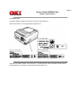
OKIPAGE 10ex
To propel your company into the future, you need technology that fits the way you work. You need the OKIPAGE® 10ex,
the best-featured desktop printer in its class. This digital LED printer combines professional performance with
excep-tional value, for years of high-quality documents and low ongoing operating costs.
Adobe Acrobat printable reference copy
of the OKIDATA Service Training Manual.
05/13/98
Note: This Adobe Acrobat version of the Okidata Service Training Manual was built with the pictures
rendered at 300 dpi, which is ideal for printing, but does not display well on most displays.
Table of Contents
Page
Service Guide OKIPAGE 10ex
0 Introduction
Introduction
1 Specifications
1.1 System Configuration
1.2 Printer Configuration
1.3 Optional Configuration
1.4 Specification
1.5 Safety Standards
....1.5.1 Certification Label
....1.5.2 Warning Label
....1.5.3 Warning/Caution Marking
2 Operation
Operation Description
2.1 Main Control Board
2.2 Power Supply/Sensor Board
2.3 Electrophotographic Process
....2.3.1 Electrophotographic Process Mechanism
....2.3.2 Electrophotographic Process
....2.3.3 Process Operation Descriptions
....2.3.4 Revision of LED Head Illumination
2.4 Paper Jam Detection
2.5 Cover Open
2.6 Toner Low Detection
3 Disassembly
3.1 Precautions for Parts Replacement
3.2 Parts Layout - [Lower base unit]
........[Upper cover unit]
........[Base unit]
3.3 How to Change Parts
....3.3.1 Upper Cover Assy
....3.3.2 IC Card Cover
....3.3.3 LED Head
....3.3.4 Operator Panel Assy
....3.3.5 Lower Base Unit
....3.3.6 Pulse Motor Main/Drum
....3.3.7 Pulse Motor (Registration)
....3.3.8 Face Up Stacker Assy
....3.3.9 Hopping Roller Assy
....3.3.10 Motor Assy
....3.3.11 Hopping Roller Shaft Assy
....3.3.12 Stacker Cover Assy
....3.3.13 Registration Roller
....3.3.14 Transfer Roller Assy
....3.3.15 Fusing Unit
....3.3.16 Back-up Roller
....3.3.17 Sensor Plate (Inlet)
....3.3.18 Sensor Plate (Outlet)
....3.3.19 Manual Feed Guide Assy
....3.3.20 Sensor Plate (Paper Supply)
1
2
3
4
5
6
7
8
9
10
11
12
13
14
15
16
17
18
19
20
21
22
23
24
25
26
27
28
29
30
31
32
33
34
35
36
37
38
39
40
41
42
43
44
45
Table of Contents
....3.3.21 Main Control M5B-PCB
....3.3.22 Transformer
....3.3.23 Power Supply/Sensor Board and Contact Assy
....3.3.24 Cassette Guide L Assy
....3.3.25 Cassette Guide R
....3.3.26 Spacer Bearing (L/R)
4 Adjustments
4. Adjustment
4.1 Maintenance Modes and Functions
....4.1.1 User Maintenance Mode
....4.1.2 System Maintenance Mode
....4.1.3 Engine Maintenance Mode
....4.1.4 EEPROM Initialization
4.2 Adjustment When Replacing a Part
4.2.1 Setting of LED Head Drive Time
4.2.2 Uploading/Downloading EEPROM data
5 Maintenance
5.1 Periodical Replacement Parts
5.2 Cleaning
....5.2.1 Cleaning of LED Lens Array
....5.2.2 Cleaning Page Function
6 Troubleshooting
6.1 Troubleshooting Tips
6.2 Points to Check before Correcting Image Problems
6.3 Tips for Correcting Image Problems
6.4 Preparation for Troubleshooting
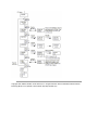
6.5 Troubleshooting Flow
....6.5.1 LCD Status Message/Problem List
....6.5.2 LCD Message Troubleshooting
........(1) The printer does not work normally after the power is
turned on.
........(2) [JAM error]
............Paper input jam
............Paper feed jam
............Paper exit jam
........(3) Paper size error
........(4) Fusing unit error (ERROR 71) (ERROR 72) (ERROR
73)
........(5) SSIO error (ERROR 74)
........(6) Fan error (ERROR 70)
....6.5.3 Image Troubleshooting
........(1) Images are light or blurred entirely
........(2) Dark background density
........(3) Blank paper is output
........(4) Black vertical belts or stripes
........(5) Cyclical defect
........(6) Prints voids
........(7) Poor fusing
........(8) Vertical belts or streaks
........Figure 6-4
Page
46
47
48
49
50
51
52
53
54
55
56
57
58
59
60
61
62
63
64
65
66
67
68
69
70
71
72
73
74
75
76
77
78
79
80
81
82
83
84
85
86
87
88
89
90
Table of Contents
........Figure 6-5
7 Wiring Diagram
7.1 Interconnect Signal Diagram
7.2 PCB Layout and Connector Signal List
7.3 Resistance Check
7.4 Short Plug Setting
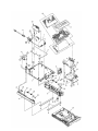
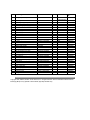
8 Parts List
Lower Base Unit
Upper Cover Unit
Base Unit
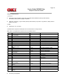
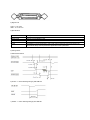
A Centronics Parallel
Centronics Parallel Interface
B Loop Test (RS-232C Interface)
Loop Test (RS-232C Interface)
C Diagnostics Test
1. Maintenance Modes
....1.1 User Maintenance Mode
....1.2 System Maintenance Mode
....1.3 Engine Maintenance Mode
....1.4 User Factory Set Operation
Product Accessory 1: RS-232C Serial Interface (Option)
RS-232C Serial Interface (Option)
Product Accessory 2: Multi-Purpose Feeder Maintenance
1. PREFACE
....1.1 Functions
....1.2 External View and Component Names
2. MECHANISM DESCRIPTION - General Mechanism
....2.2 Hopper Mechanism
3. PARTS REPLACEMENT
....3.1 Precautions Concerning Parts Replacement
....3.2 Parts Layout
....3.3 Parts Replacement Methods
........3.3.1 Link
........3.3.2 Separator
........3.3.3 OLEV-11 PCB
........3.3.4 Pulse Motor
........3.3.5 Planet Gear
........3.3.6 Roller-A and B
4. TROUBLESHOOTING - Precautions Prior to the
Troubleshooting
....4.2 Preparations for the Troubleshooting
....4.3 Troubleshooting Method
........4.3.1 LCD Status Message List
5. CONNECTION DIAGRAM - Interconnection Diagram
....5.2 PCB Layout
6. PARTS LIST
Product Accessory 3: High Capacity 2nd Paper Feeder
High Capacity Second Paper Feeder Maintenance
....1. OUTLINE - Functions
....1.2 External View and Component Names
Page
91
92
93
94
95
96
97
98
99
100
101
102
103
104
105
106
107
108
109
110
111
112
113
114
115
116
117
118
119
120
121
122
123
124
125
126
127
128
129
130
131
Table of Contents
2. MECHANISM DESCRIPTION - General Mechanism
....2.2 Hopper Mechanism
3. PARTS REPLACEMENT
....3.1 Precautions Concerning Parts Replacement
....3.2 Parts Layout
....3.3 Parts Replacement Methods
........3.3.1 Stepping Motor (Hopping)
........3.3.2 TQSB-2 PCB
........3.3.3 Hopping Roller Shaft Assembly and One-way Clutch
Gear
4. TROUBLESHOOTING - Precautions Prior to the
Troubleshooting
....4.2 Preparations for the Troubleshooting
....4.3 Troubleshooting Method
........4.3.1 LCD Status Message List
5. CONNECTION DIAGRAM
....5.1 Interconnection Diagram
....5.2 PCB Layout
6. PARTS LIST
....2nd Tray ASSEMBLY
....SECTION 1 CABINET & CASSETTE ASSEMBLY
....SECTION 2 MECHANICAL ASSEMBLY
....2nd Tray Parts List
Page
132
133
134
135
136
137
138
139
140
141
142
143
144
145
146
147
148
149
150
151
152
Page: 1
Service Guide OKIPAGE 10ex
Chapter 0 Introduction
Introduction
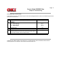
This Service Handbook describes the field maintenance methods for OKIPAGE 10ex Digital LED Printer. This manual is
written for use by the maintenance personnel. Please note that you should refer to the Printer Handbook and Printer
Setup for the handling and operating methods of the equipment.
Copyright 1998, Okidata, Division of OKI America, Inc. All rights reserved. See the OKIDATA Business Partner
Exchange (BPX) for any updates to this material. (http://bpx.okidata.com)
Page: 2
Service Guide OKIPAGE 10ex
Chapter 1 Specifications
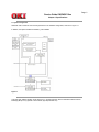
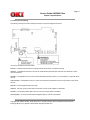
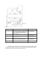
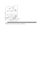
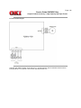
1.1 System Configuration
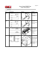
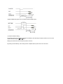
OKIPAGE 10ex consists of control and engine blocks in the standard configuration, as shown in Figure 1-1.
In addition, the options marked with asterisk (*) are available.
Figure 1-1
Copyright 1998, Okidata, Division of OKI America, Inc. All rights reserved. See the OKIDATA Business Partner
Exchange (BPX) for any updates to this material. (http://bpx.okidata.com)
Page: 3
Service Guide OKIPAGE 10ex
Chapter 1 Specifications
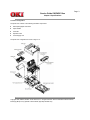
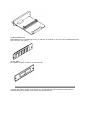
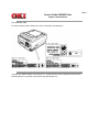
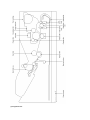
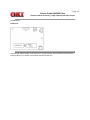
1.2 Printer Configuration
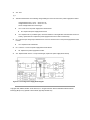
The printer unit consists of the following hardware components:
l
Electrophotographic Processor
l
Paper Feeder
l
Controller
l
Operator Panel
l
Power Supply Unit
The printer unit configuration is shown in Figure 1-2.
Copyright 1998, Okidata, Division of OKI America, Inc. All rights reserved. See the OKIDATA Business Partner
Exchange (BPX) for any updates to this material. (http://bpx.okidata.com)
Page: 4
Service Guide OKIPAGE 10ex
Chapter 1 Specifications
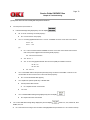
1.3 Optional Configuration
The options shown below are available for use with OKIPAGE 10ex. These are available separately from the printer unit.
(1) High Capacity Second Paper Feeder
(2) Multi-Purpose Feeder
(3) 1 MB Memory Expansion Board
(4) RS-232C Serial Interface Board
(5) DRAM SIMM Memory
DRAM SIMM memory is available with memory of 1 MB (min.) to 32 MB (max.). The access time of SIMM memories are
60ns, 70ns, 80ns, and 100ns.
(6) Flash SIMM
Flash SIMM is available with memory of 4 MB and 8 MB.
Copyright 1998, Okidata, Division of OKI America, Inc. All rights reserved. See the OKIDATA Business Partner
Exchange (BPX) for any updates to this material. (http://bpx.okidata.com)
Page: 5
Service Guide OKIPAGE 10ex
Chapter 1 Specifications
1.4 Specification
(1)
Type:
Desktop
(2)
Outside dimensions
Height: 7.9" (200 mm)
Width 13.0" (330 mm)
Depth 15.6" (395mm)
(3)
Weight
22 lbs. (10 kg)
(4)
Development method Dry electrophotography LED stationary head
Exposure method
Paper used
<Type>
l Standard paper
- Xerox 4200 (20 lbs)
l Application paper (manual face-up feed)
- Label
- Envelope
- OHP paper (Transparency)
(5)
<Size>
l Standard
Letter
Legal * [*Without Mutli-Purpose Feeder (Option)]
Legal-13*
Executive
-COM-10** [**manual feed and Multi-Purpose Feeder (Option)
only]
Monarch**
DL**
C5**
B5 (JIS)
A6
l Applicable sizes
- Width: 3.87" x 8.5" (116 to 216 mm)
- Length: 5.83" to 14" (148 to 355.6 mm)
<Thickness>
2
- Automatic feed: 16 to 28 lbs (60 to 135 g/m )
- Manual feed: Label, OHP paper (transparency), Envelope (24 to
28 lbs.)
(6)
Printing speed:
(7)
Paper feeding method Automatic paper feed or manual paper feed
(8)
Paper delivery
method
Resolution
(9)
First print: 12 seconds typical for the Letter size paper after
warm-up
Continuous print: 10 pages per minute with Letter size paper.
[Except Second Paper Feeder (8.8 PPM), Multi-Purpose Feeder
(8.3 PPM)]
o
o
Warm-up time: 60 seconds typical at room temperature [68 F (20
C), AC 120/230 V].(120 VAC for ODA, 230 VAC for OEL/INT)
Face down/face up
600 dpi x 600 dpi (true)
600 x 1200 dots/inch graphics
(10) Power input
230 VAC +/-10%
120 VAC +/-15% for
(11) Power consumption
Peak: Approx. 460W
Typical operation: Approx. 215W
Idle: Approx. 61W
Power save mode: Approx. 18W
(12) Temperature and
humidity
Temperature
In operation
50-90
(10-32)
Power off mode During Storage
32-110
14-110
(0-43)
(-10-43)
Humidity
Maximum wet bulb
temperature
20-80
77
(25)
10-90
80.4
(26.8)
10-90
-----
35.6
(2)
-----
Minimum difference 35.6
between wet and
(2)
dry bulb
temperatures
Unit
o
F
o
C
%RH
o
F
o
C
o
F
o
C
1. Storage conditions specified above apply to printers in packed condition.
2. Temperature and humidity must be in the range where no condensation occurs.
(13) Noise
During operation: 50 dB (A) or less
Standby: 38 dB (A) or less
Quite mode: Back ground level
(14) Consumables
Toner cartridge kit - 2,000 (5% duty) ---- 45g cartridge kit
Image drum cartridge - 20,000 (at continuous printing); 14,000 (3
page/job) without Power Save
Copyright 1998, Okidata, Division of OKI America, Inc. All rights reserved. See the OKIDATA Business Partner
Exchange (BPX) for any updates to this material. (http://bpx.okidata.com)
Page: 6
Service Guide OKIPAGE 10ex
Chapter 1 Specifications
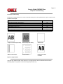
1.5 Safety Standards
1.5.1 Certification Label
1.5.2 Warning Label
1.5.3 Warning/Caution Marking
Copyright 1998, Okidata, Division of OKI America, Inc. All rights reserved. See the OKIDATA Business Partner
Exchange (BPX) for any updates to this material. (http://bpx.okidata.com)
Page: 7
Service Guide OKIPAGE 10ex
Chapter 1 Specifications
1.5.1 Certification Label
The safety certification label is affixed to the printer in the position described below.
Copyright 1998, Okidata, Division of OKI America, Inc. All rights reserved. See the OKIDATA Business Partner
Exchange (BPX) for any updates to this material. (http://bpx.okidata.com)
Page: 8
Service Guide OKIPAGE 10ex
Chapter 1 Specifications
1.5.2 Warning Label
The warning labels are affixed to the sections which may cause bodily injury.
Follow the instructions on warning labels during maintenance.
Copyright 1998, Okidata, Division of OKI America, Inc. All rights reserved. See the OKIDATA Business Partner
Exchange (BPX) for any updates to this material. (http://bpx.okidata.com)
Page: 9
Service Guide OKIPAGE 10ex
Chapter 1 Specifications
1.5.3 Warning/Caution Marking
The following warning and caution markings are made on the power supply/sensor board.
* No fuse is mounted here for 200V series.
ENGLISH - Heatsink and transformer core present risk of electric shock. Test before touching.
FRENCH - Le dissipateur thermique et le noyau du transformateur présentent des risques de choc électrique. Testez
avant de manipuler.
SPANISH - Las disipadores de color el núcel del transformador pueden producir un choque eléctrico. Compruebe antes
de tocar.
PORTUGUESE - O dissipador de calor e o núcleo do fransiormador apresentam risco de choque elétrico. Teste antes
de focar.
ENGLISH - Circuits maybe live after fuses open.
FRENCH - Il se peut que les circuits soient sous tension une fois que les fusibles ont éfé rerirés.
SPANISH - Las circuitos pueden estar activos una vez que se hayan abierio los fusibles.
PORTUGUESE - Os circuitos podem estar energizados após os fusiveis se queimarem.
Copyright 1998, Okidata, Division of OKI America, Inc. All rights reserved. See the OKIDATA Business Partner
Exchange (BPX) for any updates to this material. (http://bpx.okidata.com)
Page: 10
Service Guide OKIPAGE 10ex
Chapter 2 Operation
Operation Description
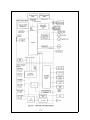
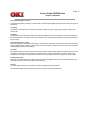
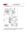
OKIPAGE 10ex consists of a main control board, a power supply/sensor board, an operator panel, an
electrophotographic process mechanism, and revision for illumination of LED head.
The main control board receives data via the host I/F, it then decodes, edits and stores the data in memory. After
completing the editing of a single page of data, it references the font memory and generates bit image data, which is
transferred to the LED head in one dot line units.
Through the electrophotographic process mechanism, the data is printed on the paper.
The operator panel is used for operations and status display.
OKIPAGE 10ex block diagram is shown in Figure 2-1.
Copyright 1998, Okidata, Division of OKI America, Inc. All rights reserved. See the OKIDATA Business Partner
Exchange (BPX) for any updates to this material. (http://bpx.okidata.com)
Page: 11
Service Guide OKIPAGE 10ex
Chapter 2 Operation
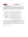
2.1 Main Control Board
The main control board consists of a single chip CPU, two program/font ROMs, four DRAMs, an EEPROM, a host
interface circuit, and a mechanism driving circuit.
(1) Single chip CPU
The single chip CPU is a custom CPU (32-bit internal bus, 32-bit external bus, 28.24-MHz clock, with input frequency
from a 7.06-MHz clock) which incorporates the RISC CPU and its peripheral devices, and has the following functions:
Built-in Device
Function
Chip select controller
Bus controller
DRAM controller
DMA controller
Control of ROM, DRAM and I/O device.
Parallel interface controller
Control of Centronics parallel interface.
Serial interface controller
Video output port
LED STB output port
Control of RS-232C serial interface.
Controls LED head.
Timer
Generation of various control timing
Monitoring of paper running and paper size.
I/O Port
Input and output of sensor and motor signals.
Transfer of image data from DRAM to video output port.
(2) Program and Font ROMs
The Program and Font ROMs store the equipment program and various types of fonts. Mask ROM is used as Program
and Font ROMs. The mounting locations of these Program and Font ROMs vary depending on the type of the ROMs.
(3) DRAM
The DRAM is a 2MB resident memory on the main control board that stores edited data, image data, DLL data and
macro data.
(4) EEPROM
1,024-bit Electrically Erasable PROM (EEPROM), is loaded with the following kinds of data:
l
l
l
Menu data
Various counter data (page counter, drum counter)
Adjusting parameters (LED head drive time, print start position, paper feed length)
(5) Parallel Interface
Parallel data is received from a host system via parallel interface which conforms to the IEEE 1284 specification.
Copyright 1998, Okidata, Division of OKI America, Inc. All rights reserved. See the OKIDATA Business Partner
Exchange (BPX) for any updates to this material. (http://bpx.okidata.com)
Page: 12
Service Guide OKIPAGE 10ex
Chapter 2 Operation
2.2 Power Supply/Sensor Board
The power supply/sensor board consists of an AC filter circuit, a low voltage power supply circuit, a high voltage power
supply circuit, heater drive circuit, and photosensors.
(1) Low Voltage Power Supply Circuit
This circuit generates the following voltages.
Output voltage
+5 V
+38 V
+8V
-8V
+ 3.3 V
Application
Logic circuit supply voltage.
Motor and fan drive voltage and source voltage for high-voltage supply.
RS-232C line voltage.
RS-232C line voltage and PS board supply voltage.
LED head supply voltage
(2) High Voltage Power Supply Circuit
This circuit generates the following voltages required for electrophotographic process from +5 V, according to the control
sequence from the main control board. When cover open state is detected, +5 V supply is interrupted automatically to
stop the supply of all high-voltage outputs.
Output
Voltage
Application
CH
-1.3 KV
Voltage to be applied to charge roller.
DB
-265 V/+300 V
Voltage to be applied to a developing roller.
SB
-500 V/ 0 V
Voltage to be applied to a sponge roller.
CB
+400 V/+3.5 KV
Voltage to be applied to a cleaning roller.
TR
+500 V to +3.5 KV/-1100 V
Voltage to be applied to a transfer roller. (Variable)
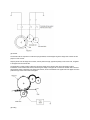
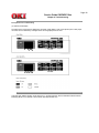
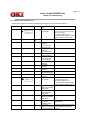
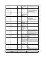
(3) Photosensor
The photosensor mounted on this power supply/sensor board monitors the status of paper being fed through the printer
during printing.
The sensor layout diagram is shown in Figure 2-2 below.
Figure 2-2
Sensor
Function
Inlet sensor 1
Detects the leading part of the paper and gives the ON: Paper exists.
monitor timing for switching from hopping operation OFF: No paper exists.
to feeding operation. Monitors paper feeding
situation and paper size based on the paper arrival
time and running time.
Detects the paper width.
ON: A4 or larger.
OFF: Smaller than A4.
Detects the leading portion of the paper. Monitors
ON: Paper exists.
paper feeding situation.
OFF: No paper exists.
Inlet sensor 2
Paper sensor
Sensing State
Output sensor
Monitors paper feeding and size according to the
time of arrival to and leaving past the sensor.
ON: Paper exists.
OFF: No paper exists.
Toner sensor
Detects the lack of toner.
-----
Copyright 1998, Okidata, Division of OKI America, Inc. All rights reserved. See the OKIDATA Business Partner
Exchange (BPX) for any updates to this material. (http://bpx.okidata.com)
Page: 13
Service Guide OKIPAGE 10ex
Chapter 2 Operation
2.3 Electrophotographic Process
2.3.1 Electrophotographic Process Mechanism
2.3.2 Electrophotographic Process
2.3.3 Process Operation Descriptions
2.3.4 Revision of LED Head Illumination
Copyright 1998, Okidata, Division of OKI America, Inc. All rights reserved. See the OKIDATA Business Partner
Exchange (BPX) for any updates to this material. (http://bpx.okidata.com)
Page: 14
Service Guide OKIPAGE 10ex
Chapter 2 Operation
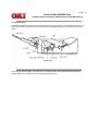
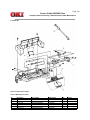
2.3.1 Electrophotographic Process Mechanism
This mechanism actuates the printing of image data supplied by the main control board on the paper by
electrophotographic process.
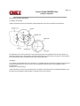
The layout of the electrophotographic process mechanism is shown in Figure 2-3.
(1) Image Drum Unit
The image drum unit consists of a sensitive drum, a charger, and a developer. The unit forms a toner image on the
sensitive drum, using a electrostatic latent image formed by the LED head.
(2) Registration Motor
The registration motor is a pulse motor of 48 steps/rotation with two-phase excitement by the signal from the main
control board. It drives the hopping and registration rollers via two one-way clutches according to the direction of
rotation.
(3) Main (Drum) Motor
The main or drum motor is a pulse motor of 48 steps/rotation with two-phase excitement by the signal from the main
control board and is the main motor of this mechanism.
(4) LED Head
Image data for each dot line from the main control board is received by the shift register and latch register. The 4992
LED's are driven to radiate the image data on the image drum.
(5) Fuser
The fuser consists of a heater, a heat roller, a thermistor and a thermostat.
The AC voltage from the power supply/sensor board is applied to the heater controlled by the HEATON signal from the
main control board. This AC voltage heats the heater. The main control board monitors the heat roller temperature via
the thermistor, and regulates the heater roller to keep it at a designated temperature in the menu, depending on the
thickness of the paper (tray 1&2: light=165°C, medium light=170°C, medium=175°C, medium heavy and heavy=195°C;
manual feeding and power envelope feeder: light=175°C, medium light=180°C, medium=185°C, medium heavy=190°C,
heavy=195°C, transparency = 160°C) by connecting or disconnecting the AC voltage supply to the heater.
When an abnormal rise of the heater roller temperature takes place, the thermostat of the heater voltage supply circuit
becomes active and forcibly cuts the AC voltage supply.
The temperature setting of the fuser can be changed through operator panel setting.
Copyright 1998, Okidata, Division of OKI America, Inc. All rights reserved. See the OKIDATA Business Partner
Exchange (BPX) for any updates to this material. (http://bpx.okidata.com)
Page: 15
Service Guide OKIPAGE 10ex
Chapter 2 Operation
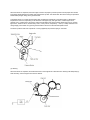
2.3.2 Electrophotographic Process
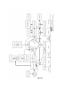
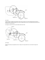
The electrophotographic processing is outlined below. The electrophotographic printing process is shown in Figure 2-4
(see below).
1 Charging
The surface of the image drum is charged uniformly with a negative charge by applying the negative voltage to the
charge roller.
2 Exposure
Light emitted from the LED head irradiates the negatively charged surface of the image drum. The surface potential of
the irradiated portion of the image drum surface becomes lower, forming the electrostatic latent image associated with
the print image.
3 Developing and toner recovery
When the negatively charged toner is brought into contact with the image drum, it is attracted to the electrostatic latent
image by static electricity, making the image visible. At the same time, the residual toner on the image drum is attracted
to the developing roller by static electricity.
4 Transfer
When paper is placed over the image drum surface, the positive charge which is opposite in polarity to that of the toner,
is applied to the reverse side of the paper by the transfer roller. The toner is attracted by the positive charge and is
transferred onto the paper. This results in the transfer of the toner image formed on the image drum onto the paper.
5 Temporary cleaning
Residual toner which remains on the image drum without being transferred is evened out by the cleaning roller and is
temporarily attracted to the cleaning roller by static electricity.
6 Fusing
The toner image transferred onto the paper is fused to the paper by heat and pressure.
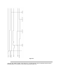
An electrophotographic process timing chart is shown in Figure 2-5 (see last chart below).
Figure 2-4
Figure 2-5
Copyright 1998, Okidata, Division of OKI America, Inc. All rights reserved. See the OKIDATA Business Partner
Exchange (BPX) for any updates to this material. (http://bpx.okidata.com)
Page: 16
Service Guide OKIPAGE 10ex
Chapter 2 Operation
2.3.3 Process Operation Descriptions
(1) Hopping and Feeding
Hopping and feeding motions are actuated by a single registration motor in the mechanism as shown below:
The registration motor turning in direction "a" drives the hopping roller. The registration motor turning in direction "b"
drives the registration roller. The registration and hopping gears have one-way bearing, so turning any of these gears in
the reverse direction will not transmit the motion to the corresponding roller.
(a) Hopping
1 For hopping, the registration motor turns in direction "a" (clockwise direction) and drives the hopping roller to advance
the paper until the inlet sensor turns on (in this case, the registration gear also turns, but the registration roller is
prevented from
turning by the one-way bearing).
2 After inlet sensor is turned on by the paper advance, the paper is further advanced to a predetermined distance until
the paper hits the registration roller (the skew of the paper can thus be corrected).
(b) Feeding
1 When hopping is completed, the registration motor turning in direction "b" (counter-clockwise direction) drives the
registration roller to advance the paper (in this case, the hopping gear also turns, but the hopping roller is prevented from
turning by the one-way bearing).
2 The paper is further advanced in synchronization with the print data.
(2) Charging
Charging is actuated by the application of the DC voltage to the charge roller that is in contact with the image drum
surface.
The charge roller is composed of two layers, a conductive layer and a surface protective layer, both having elasticity to
secure good contact with the image drum. When the DC voltage applied by the power supply exceeds the threshold
value, charging begins. The applied voltage is proportional to the charge potential, with offset of approximately -550V.
(3) Exposure
Light emitted by the LED head irradiates the image drum surface with a negative charge. The surface potential of the
irradiated portion of the image drum drops, forming an electrostatic latent image associated with the image signal.
The image drum is coated with an underlayer (UL), a carrier generation layer (CGL), and carrier transfer layer (CTL) on
aluminum base. The organic photo conductor layer (OPC), comprising CTL and CGL, is about 20 mm thick.
The image roller surface is charged to about -750 V by the contact charge of the charge roller.
When the light from the LED head irradiates the image drum surface, the light energy generates positive and negative
carriers in the CGL. The positive carriers are moved to the CTL by an electrical field acting on the image drum. Likewise,
the negative carriers flow into the aluminum layer (ground).
The positive carriers moved to the CTL combine with the negative charges on the image drum surface accumulated by
the contact charge of the charge roller, lowering the potential on the image drum surface. The resultant drop in the
potential of the irradiated portion of the image drum surface forms an electrostatic latent image on it. The irradiated
portion of the image drum surface is kept to about -100 V.
(4) Developing
Toner is attracted to the electrostatic latent image on the image drum surface, converting it into a visible toner image.
Developing takes place through the contact between the image drum and the developing roller.
1 As the toner supply roller rotates while rubbing on the developing roller, a friction charge is generated between the
developing roller and the toner, allowing the toner to be attracted to the developing roller (the developing roller surface is
charged positive and the toner, negative).
2 The toner attracted to the developing roller is scraped off by the doctor blade, forming a thin coat of toner on the
developing roller surface.
3 Toner is attracted to the exposed portion (low-potential part) of the image drum at the contact of the image drum and
the developing roller, making the electrostatic latent image visible.
An illustration of activities at the contact point of the image drum surface and the developing roller (arrow marks denote
the direction of the electrical field).
Note: The bias voltage required during the developing process is supplied to the toner supply roller and the developing
roller, as shown below. -500 VDC is supplied to the toner supply roller, -265 VDC to the developing roller.
(5) Transfer
The transfer roller is composed of conductive sponge material, and is designed to get the image drum surface and the
paper in a close contact.
Paper is placed over the image drum surface, and the positive charge, opposite in polarity to that of the toner, is applied
to the paper from the reverse side.
The application of a high positive voltage from the power supply to the transfer roller causes the positive charge
inducement on the transfer roller surface, transferring the charge to the paper as it contacts the transfer roller. The toner
with negative charge is attracted to the image drum surface, and it is transferred to the upper side of the paper due to the
positive charge on the reverse side of the paper.
(6) Fusing
When the transfer is completed, the toner image is fused to the paper by heat and pressure as the paper with unfused
toner image passes between the heater roller and the back-up roller. The heater roller with Teflon coating incorporates a
400W heater (Halogen lamp), which generates heat.
A thermistor which is in contact with the heater roller regulates the temperature of the heater roller to a designated
temperature in the menu, depending on the thickness of the paper (tray 1&2: light=165°C, medium light=170°C,
medium=175°C, medium heavy and heavy=195°C/manual feeding and power envelope feeder: light=175°C, medium
light=180°C, medium=185°C, medium heavy=190°C, heavy=195°C, transparency = 160°C). A safety thermostat cuts
voltage supply to the heater off by opening the thermostat in the event of abnormal temperature rises.
The back-up roller is held under a pressure of 3.76 kg applied by the pressure spring on each side.
(7) Cleaning
When the transfer is completed, the residual toner left on the image drum is attracted to the cleaning roller temporarily by
static electricity, and the image drum surface is cleaned.
(8) Cleaning of rollers
The charge, transfer and cleaning rollers are cleaned for the following cases:
l
l
l
Warming up when the power is turned on.
Warming up after the opening and closing of the cover.
When the number of sheets accumulated reaches 10 or more, and the printout operation ends.
Changes in bias voltage applied to each roller move the attaching toner off the roller to the image drum and return it to
the developer.
Copyright 1998, Okidata, Division of OKI America, Inc. All rights reserved. See the OKIDATA Business Partner
Exchange (BPX) for any updates to this material. (http://bpx.okidata.com)
Page: 17
Service Guide OKIPAGE 10ex
Chapter 2 Operation
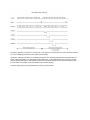
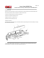
2.3.4 Revision of LED Head Illumination
An LED correcting head, which is capable of correcting the illumination of the LED for each dot, is being used in this
printer. LED illumination correction function of 16 steps is carried out by using an EEPROM which is installed in the LSI
that maintains the LED illumination correction values, and an LED correction drivers (MSM6731BWAF or
MSM6732BWAF) together as a pair. The LED correcting head consists of the correction control LSI (MSM6730WAF),
LED drivers (MSM6731BWAF or MSM6732BWAF), and an LED array. The block diagram of the LED correcting head
is shown below.
The existing LED head receives the printing data from the CPU directly at its LED drivers. With the LED correcting head,
a correction control LSI (MSM6730WAF) is connected between the CPU and LED drivers, so the printing data is input
to the LED drivers through the correction control LSI. In order to maintain compatibility with the existing LED head, the
printing operation of the LED correcting head is carried out through identical sequence.
The LED correcting head is a 600 dpi head, with the LED drivers located on both sides of the LED array with a 300 dpi
pitch spacing. The printing and correction data obtained from the CPU through four signal lines are sent to the LED
array.
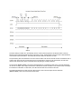
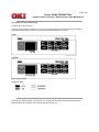
The printing operation timing chart is shown below.
The printing operation is carried out in normal mode. Under ordinary circumstances such as when the power is turned
on or when LOADI signal level is low, the normal mode is enabled.
The printing operation is carried out in the following sequence. First, the printing data DATA13 through DATA10 are
stored, sequentially shifted, in the shift registers of the LED drivers, by the printing data synchronous clock, CLOCK.
Then the printing data stored in shift registers are latched by the high level pulse of LOAD. The latched printing data
turns the LEDs on by STRB11-N through STRB41-N and actuates printing.
The mode setting timing chart during illumination correction is shown below.
The mode setting is carried out in the following manner. LOAD is fixed at high level, and DATA10 which comes up
following this is 4-data latched with the timing of the fall of CLOCK. The illumination correction mode is selected based
on the latched 4-data combination. Then the mode becomes valid at the fifth fall of CLOCKI.
The period during which the illumination correction mode is valid is from the fall of the fifth CLOCK and while the level of
LOAD is high. When the level of LOAD becomes low, the illumination correction mode is terminated, and the head
returns to the normal mode, which is mode with which the printing is normally carried out.
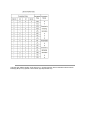
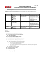
The LED driver (MSM6731BWAF) corrects the LED illumination by controlling the LED current. The LED illumination
can be set in 16 steps, with 7 steps in the direction of illumination increase in relation to the standard value, and 8 steps
in the direction of decrease. For this reason, the LED correction data is a 4-bit data for each dot.
The relationship between the LED correction data and LED current correction steps with the LED driver
(MSM6731BWAF) used in an LED head is shown below.
Copyright 1998, Okidata, Division of OKI America, Inc. All rights reserved. See the OKIDATA Business Partner
Exchange (BPX) for any updates to this material. (http://bpx.okidata.com)
Page: 18
Service Guide OKIPAGE 10ex
Chapter 2 Operation
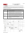
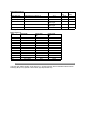
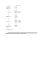
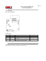
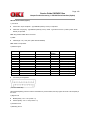
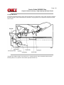
2.4 Paper Jam Detection
The paper jam detection function monitors the paper condition when the power is turned on and during printing. When
any of the following conditions arises, this function interrupts the printing process. If any of the following errors is
encountered, printing can be recovered by removing the jammed paper (by opening the upper cover, removing the
jammed paper and closing the upper cover).
Error
Cause of error
Paper input jam
l
l
Paper feed jam
l
l
l
Paper exit jam
Paper size error
l
l
l
l
l
l
l
Paper Feed Timing Chart
The paper is in contact with the inlet sensor when the power is turned on.
After hopping operation is attempted three times, the leading edge of the paper
does not reach the inlet sensor.
The paper is in contact with the paper sensor when the power is on.
The leading edge of the paper does not reach the paper sensor within a
predetermined feeding distance since the paper has reached the inlet sensor.
The leading edge of paper does not reach the outlet sensor within a
predetermined feeding distance after the paper has reached the paper sensor.
The paper is in contact with the outlet sensor when the power is turned on.
The paper does not pass over the outlet sensor within a predetermined feeding
distance after the leading edge of the paper has reached the outlet sensor.
The paper size check for manual feeding finds that the paper size is free size.
The size of the paper is monitored by the inlet sensor 1. The paper is not detected
by the inlet sensor 1 within predetermined feeding distance.
The inlet sensor 2 detects that the size of the loaded paper is A4 or larger, or
smaller than A4.
The detected paper size differs from the paper size set by command or menu.
The paper size check for manual feeding finds that the paper size is free size.
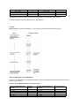
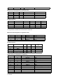
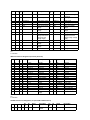
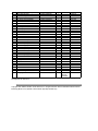
Paper Feed Check List
Type of error
Monitor
Standard Value
Paper feed error
Paper feed jam
Paper feed jam
Paper size error
Hopping start to In Sensor on
In sensor on to Write sensor on
Write sensor on to Out sensor on
In sensor on to Out sensor on
Paper exit jam
Out sensor on to Out sensor off
Paper feed jam
In sensor off to Write sensor off
72.0
20.0
140.5
Depends on the
paper length
Depends on the
paper length
22.2
Error
Plus
Error
Minus
36.0
22.0
25.0
45.0
45.0
45.0
45.0
22.0
-
Note: Hyphen "-" in the table represents "not checked".
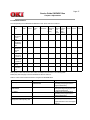
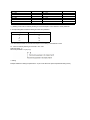
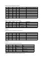
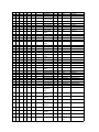
Paper Length List
Type
Paper length
A4
A5
B5
LETTER
LEGAL 13
LEGAL 14
EXEC
A6
Monarch
COM-9
COM-10
DL
C5
Free
297.0
210.0
257.0
279.4
330.2
355.6
266.7
148.0
190.5
225.4
241.3
220.0
229.0
110.1-355.6
Check range
Min.
252.0
165.0
212.0
234.4
285.2
310.6
221.7
103.0
145.5
180.4
196.3
175.0
184.0
65.0
Check range
Max.
342.0
255.0
302.0
324.4
375.2
400.6
311.7
193.0
235.5
270.4
286.3
265.0
274.0
400.6
Copyright 1998, Okidata, Division of OKI America, Inc. All rights reserved. See the OKIDATA Business Partner
Exchange (BPX) for any updates to this material. (http://bpx.okidata.com)
Page: 19
Service Guide OKIPAGE 10ex
Chapter 2 Operation
2.5 Cover Open
When the stacker cover is opened, the cover open microswitch on the power supply/sensor board is turned off to cut
+5V supply to the high voltage power supply circuit. This results in the interruption of all high-voltage outputs. At the
same time, the CVOPN signal is sent to the main control board to notify that the microswitch is off, and the main control
board carries out the cover open process.
Copyright 1998, Okidata, Division of OKI America, Inc. All rights reserved. See the OKIDATA Business Partner
Exchange (BPX) for any updates to this material. (http://bpx.okidata.com)
Page: 20
Service Guide OKIPAGE 10ex
Chapter 2 Operation
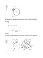
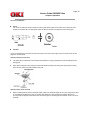
2.6 Toner Low Detection
l
Device
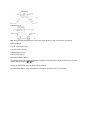
The Toner Low Detection device consists of a stirring gear which rotates at a constant rate, a stirring bar and a
magnet on the stirring bar. The stirring bar rotation is driven by the link to the protrusion in the stirring gear.
l
Operation
Toner Low is detected by monitoring the time interval of the encounter of the magnet set on the sensor lever and the
magnet on the stirring bar.
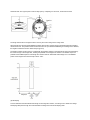
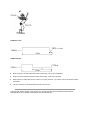
Operation during Toner Full state
l
The stirring bar is rotated due to the mechanical transmission of energy originating from the interlocking with the
stirring gear.
l
Even when the magnet on the stirring bar reaches the maximum height, the stirring bar is pushed by the stirring
gear, since the other end is being dipped in the toner.
Operation during Toner Low state
l
When the stirring bar reaches the maximum height, it falls to the minimum height due to its own weight, since there
is no resistance provided by the toner on the other side. Because of this, the time interval during which it is in
encounter with the magnet of the sensor lever becomes longer. By monitoring this time interval, Toner Low can be
detected.
TONER FULL state
TONER LOW state
l
When the Toner Low state is detected 2 times consecutively, Toner Low is established.
l
When the Toner Full state is detected 2 times consecutively, Toner Low is canceled.
l
When there is no change with the toner sensor for 2 cycles (4.875 sec. x 2) or more, then the Toner Sensor Alarm
is activated.
l
The toner sensor is not monitored while the drum motor is in halt.
Copyright 1998, Okidata, Division of OKI America, Inc. All rights reserved. See the OKIDATA Business Partner
Exchange (BPX) for any updates to this material. (http://bpx.okidata.com)
Page: 21
Service Guide OKIPAGE 10ex
Chapter 3 Disassembly
3.1 Precautions for Parts Replacement
The section explains the procedures for replacement of parts, assemblies, and units in the field. Only the disassembly
procedures are explained here. For reassembly, reverse the steps of disassembly procedure.
(1) Before starting the parts replacement, remove the AC power cord and interface cable.
(a) Remove the AC power cord in the following sequence:
i) Turn off ("o") the power switch of the printer.
ii) Disconnect the AC inlet plug of the AC power cord from the AC receptacle.
iii) Disconnect the AC power cord and interface cable from the printer.
(b) Reconnect the printer in the following sequence.
i) Connect the AC power cord and interface cable to the printer.
ii) Connect the AC inlet plug to the AC receptacle.
iii) Turn on ("l") the power switch of the printer.
(2) Do not try to disassemble as long as the printer is operating normally.
(3) Do not remove parts which do not need to be touched; try to keep the disassembly to a minimum.
(4) Use specified service tools.
(5) When disassembling, follow the procedure in sequence laid out in this manual. Parts may be damaged if these
sequences are not followed.
(6) Since screws, collars and other small parts are likely to be lost, they should temporarily be attached to the original
positions during disassembly.
(7) When handling IC's such as microprocessors, ROM's and RAM's, or circuit boards, do not wear gloves that are likely
to generate static electricity.
(8) Do not place printed circuit boards directly on the equipment or floor.
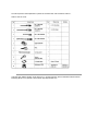
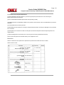
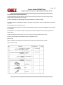
[Service Tools]
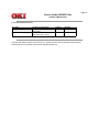
The tools required for field replacement of printed circuit boards and units are listed in Table 3-1.
Table 3-1 Service Tools
Copyright 1998, Okidata, Division of OKI America, Inc. All rights reserved. See the OKIDATA Business Partner
Exchange (BPX) for any updates to this material. (http://bpx.okidata.com)
Page: 22
Service Guide OKIPAGE 10ex
Chapter 3 Disassembly
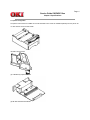
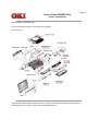
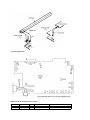
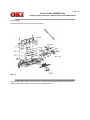
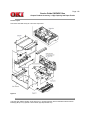
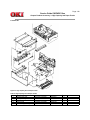
3.2 Parts Layout - [Lower base unit]
This section describes the layout of main parts of the equipment.
[Lower base unit]
Copyright 1998, Okidata, Division of OKI America, Inc. All rights reserved. See the OKIDATA Business Partner
Exchange (BPX) for any updates to this material. (http://bpx.okidata.com)
Page: 23
Service Guide OKIPAGE 10ex
Chapter 3 Disassembly
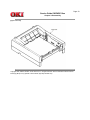
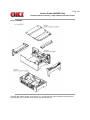
[Upper cover unit]
Copyright 1998, Okidata, Division of OKI America, Inc. All rights reserved. See the OKIDATA Business Partner
Exchange (BPX) for any updates to this material. (http://bpx.okidata.com)
Page: 24
Service Guide OKIPAGE 10ex
Chapter 3 Disassembly
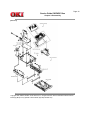
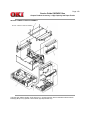
[Base unit]
Copyright 1998, Okidata, Division of OKI America, Inc. All rights reserved. See the OKIDATA Business Partner
Exchange (BPX) for any updates to this material. (http://bpx.okidata.com)
Page: 25
Service Guide OKIPAGE 10ex
Chapter 3 Disassembly
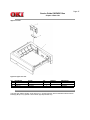
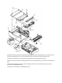
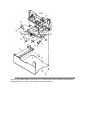
3.3 How to Change Parts
This section explains how to change parts and assemblies listed in the disassembly diagram below.
3.3.1 Upper cover
3.3.2 IC Card Cover
3.3.3 LED head
3.3.4 Operator Panel Assy
3.3.5 Lower Base Unit
3.3.6 Pulse Motor (Main/Drum)
3.3.7 Pulse Motor (Registration)
3.3.8 Face Up Stacker Assy
3.3.9 Eject Roller Assy
3.3.10 Motor Assy
3.3.11 Hopping Roller Shaft Assy
3.3.12 Stacker Cover Assy
3.3.13 Registration Roller
3.3.14 Back-up roller
3.3.15 Sensor plate (inlet)
3.3.16 Toner sensor
3.3.17 Sensor plate (outlet)
3.3.18 Manual feed guide assy
3.3.19 Sensor plate (Paper supply)
3.3.20 Main control PCB
3.3.21 Power supply board and contact assy
3.3.22 Transformer
3.3.23 Power supply/sensor board and contact assy
3.3.24 Cassette guide (L)
3.3.25 Cassette guide (R)
Copyright 1998, Okidata, Division of OKI America, Inc. All rights reserved. See the OKIDATA Business Partner
Exchange (BPX) for any updates to this material. (http://bpx.okidata.com)
Page: 26
Service Guide OKIPAGE 10ex
Chapter 3 Disassembly
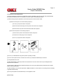
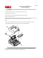
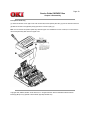
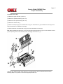
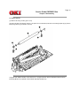
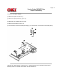
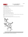
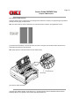
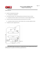
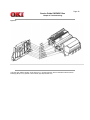
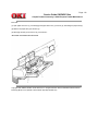
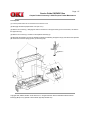
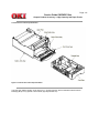
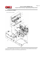
3.3.1 Upper Cover Assy
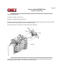
(1) With the power switch turned off, unplug the AC power cord from the outlet.
(2) Disconnect the interface cable (1).
(3) Press the knobs (2) on left and right sides and open the stacker cover assy (3).
(4) Take out the image drum unit (4).
(5) Remove two screws (5), and open the manual feed guide assy (6). Lift the front side of the upper cover (7) up and
unlock the latches at two locations on the back side. Lift and remove the upper cover assy (7).
Notes:
1. When removing or reinstalling the upper cover, be careful not to get the motor cables tangled or caught.
2. When reinstalling the screws (5), be sure to direct the screws into preexisting threads.
Copyright 1998, Okidata, Division of OKI America, Inc. All rights reserved. See the OKIDATA Business Partner
Exchange (BPX) for any updates to this material. (http://bpx.okidata.com)
Page: 27
Service Guide OKIPAGE 10ex
Chapter 3 Disassembly
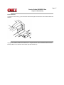
3.3.2 IC Card Cover
(1) Open the IC card cover (1), press it from both sides at the hinges in the directions of arrows shown below and
remove it.
Copyright 1998, Okidata, Division of OKI America, Inc. All rights reserved. See the OKIDATA Business Partner
Exchange (BPX) for any updates to this material. (http://bpx.okidata.com)
Page: 28
Service Guide OKIPAGE 10ex
Chapter 3 Disassembly
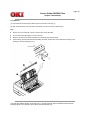
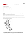
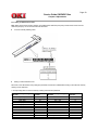
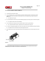
3.3.3 LED Head
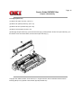
(1) Press the knobs on left and right sides and open the stacker cover assy (1).
(2) Open the hook section on the left side of the stacker cover and remove the LED head (2).
Note:
l
Be sure not to touch directly or push on the SLA part of the LED head.
l
Do not remove the LED cable 3 from the connector.
l
Remove connector 4 and cable 3 together as an assembly from the LED head.
l
After mounting the new LED head and reinstalling the cable, set drive time of the LED head according to the
marking on the LED head (see 4.2.1).
Copyright 1998, Okidata, Division of OKI America, Inc. All rights reserved. See the OKIDATA Business Partner
Exchange (BPX) for any updates to this material. (http://bpx.okidata.com)
Page: 29
Service Guide OKIPAGE 10ex
Chapter 3 Disassembly
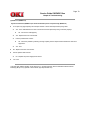
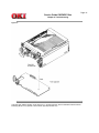
3.3.4 Operator Panel Assy
(1) Unlock two latches on the upper cover from the rear side, lift the operator panel assy (1) from the back and remove it.
(2) Remove the Sumi card (operator panel) (2) from the connector (CN1) (3).
Note: You can remove the operator panel assy while the upper cover installed on the unit. However, it is much easier to
remove the panel assy after removal of upper cover.
Copyright 1998, Okidata, Division of OKI America, Inc. All rights reserved. See the OKIDATA Business Partner
Exchange (BPX) for any updates to this material. (http://bpx.okidata.com)
Page: 30
Service Guide OKIPAGE 10ex
Chapter 3 Disassembly
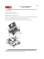
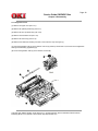
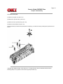
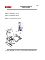
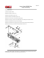
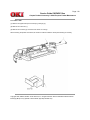
3.3.5 Lower Base Unit
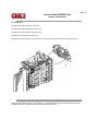
(1) Remove the upper cover (see 3.3.1).
(2) Remove the operator panel assy (see 3.3.4).
(3) Remove the face up stacker assy (see 3.3.8)
(4) Remove the connecting cables (2) and (3) of the pulse motors from the connectors (DM, RM) of the M5B-PCB (1).
(5) Remove the LED head cables (4) and (5) from the connectors (HEAD1, HEAD2).
(6) Open the manual feed guide assy, remove six screws (7), then remove the lower base unit (6).
Copyright 1998, Okidata, Division of OKI America, Inc. All rights reserved. See the OKIDATA Business Partner
Exchange (BPX) for any updates to this material. (http://bpx.okidata.com)
Page: 31
Service Guide OKIPAGE 10ex
Chapter 3 Disassembly
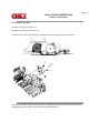
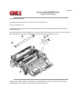
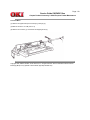
3.3.6 Pulse Motor Main/Drum
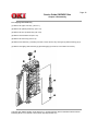
(1) Remove the upper cover (see 3.3.1).
(2) Remove the lower base unit (see 3.3.5).
(3) Remove two screws (1) and remove the pulse motor (main drum) (2) from the motor bracket (3).
Copyright 1998, Okidata, Division of OKI America, Inc. All rights reserved. See the OKIDATA Business Partner
Exchange (BPX) for any updates to this material. (http://bpx.okidata.com)
Page: 32
Service Guide OKIPAGE 10ex
Chapter 3 Disassembly
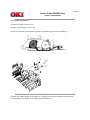
3.3.7 Pulse Motor (Registration)
(1) Remove the upper cover (see 3.3.1).
(2) Remove the lower base unit (see 3.3.5).
(3) Remove two screws (1) and remove the pulse motor (registration) (2) from the motor bracket (3).
Copyright 1998, Okidata, Division of OKI America, Inc. All rights reserved. See the OKIDATA Business Partner
Exchange (BPX) for any updates to this material. (http://bpx.okidata.com)
Page: 33
Service Guide OKIPAGE 10ex
Chapter 3 Disassembly
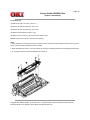
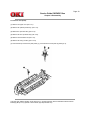
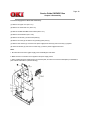
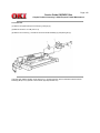
3.3.8 Face Up Stacker Assy
(1) Remove the upper cover (see 3.3.1).
(2) Remove the operator panel assy (see 3.3.4).
(3) Remove the screw (1) and remove the Sumi card (operator panel cable) (2) off the latch section of face up stacker
(4). Remove both the shield plate (3) and face up stacker (4) together.
(4) Unlock the latches at two locations, and remove the face up stacker (4).
Copyright 1998, Okidata, Division of OKI America, Inc. All rights reserved. See the OKIDATA Business Partner
Exchange (BPX) for any updates to this material. (http://bpx.okidata.com)
Page: 34
Service Guide OKIPAGE 10ex
Chapter 3 Disassembly
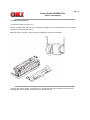
3.3.9 Hopping Roller Assy
(1) Remove the upper cover assy (see 3.3.1).
(2) Remove the operator panel assy (see 3.3.4).
(3) Remove the face up stacker assy (see 3.3.8).
(4) Remove the lower base unit (see 3.3.5).
(5) Disengage the eject roller assy (1) from the lower base (2) by pressing the latch section of the eject roller assy (1) in
the direction of the arrow shown below, and remove the eject roller assy (1).
Copyright 1998, Okidata, Division of OKI America, Inc. All rights reserved. See the OKIDATA Business Partner
Exchange (BPX) for any updates to this material. (http://bpx.okidata.com)
Page: 35
Service Guide OKIPAGE 10ex
Chapter 3 Disassembly
3.3.10 Motor Assy
(1) Remove the upper cover assy (see 3.3.1).
(2) Remove the operator panel assy (see 3.3.4).
(3) Remove the face up stacker assy (see 3.3.8).
(4) Remove the lower base unit (see 3.3.5).
(5) Stand the lower base unit on its side as shown, and unlock two latches, then remove the motor assy (1).
Copyright 1998, Okidata, Division of OKI America, Inc. All rights reserved. See the OKIDATA Business Partner
Exchange (BPX) for any updates to this material. (http://bpx.okidata.com)
Page: 36
Service Guide OKIPAGE 10ex
Chapter 3 Disassembly
3.3.11 Hopping Roller Shaft Assy
(1) Remove the upper cover assy (see 3.3.1).
(2) Remove the operator panel assy (see 3.3.4).
(3) Remove the face up stacker assy (see 3.3.8).
(4) Remove the lower base unit (see 3.3.5).
(5) Remove the motor assy (see 3.3.10).
(6) With the lower base unit (1) standing on its side, remove the one-way clutch gear (2) and the bearing (A) (3).
(7) Remove the hopping roller shaft assy (4) (the bearing (B) (5) comes off, so be careful not to lose it).
Copyright 1998, Okidata, Division of OKI America, Inc. All rights reserved. See the OKIDATA Business Partner
Exchange (BPX) for any updates to this material. (http://bpx.okidata.com)
Page: 37
Service Guide OKIPAGE 10ex
Chapter 3 Disassembly
3.3.12 Stacker Cover Assy
(1) Remove the upper cover assy (see 3.3.1).
(2) Remove the operator panel assy (see 3.3.4).
(3) Remove the face up stacker assy (see 3.3.8).
(4) Remove the reset lever R (1).
(5) Detach the reset spring (2) from the lower base unit (3), turn the reset lever L (4) in the direction of arrow (A) until it
stops, and remove it in the direction of arrow (B).
(6) Unlock two latches of the lower base unit (3), then remove the stacker cover assy (5).
Note: When reinstalling the reset level L (4), fit it onto the guide of the lower base unit (3), turn it in the direction of arrow
(C) while pressing down the shaft of back up roller, and engage the reset lever L (4).
Copyright 1998, Okidata, Division of OKI America, Inc. All rights reserved. See the OKIDATA Business Partner
Exchange (BPX) for any updates to this material. (http://bpx.okidata.com)
Page: 38
Service Guide OKIPAGE 10ex
Chapter 3 Disassembly
3.3.13 Registration Roller
(1) Remove the upper cover (see 3.3.1).
(2) Remove the operator panel assy (see 3.3.4).
(3) Remove the face up stacker assy (see 3.3.8).
(4) Remove the lower base unit (see 3.3.5).
(5) Remove the motor assy (see 3.3.10).
(6) With the lower base unit standing on its side, remove the one-way clutch gear (1).
(7) Press the registration roller (2) in the direction of arrow (A) and lift up the left side of it, then remove the registration
roller (2) and the bearing (registration) (3).
(8) Pull out the registration roller (2) in the direction of arrow (B).
Copyright 1998, Okidata, Division of OKI America, Inc. All rights reserved. See the OKIDATA Business Partner
Exchange (BPX) for any updates to this material. (http://bpx.okidata.com)
Page: 39
Service Guide OKIPAGE 10ex
Chapter 3 Disassembly
3.3.14 Transfer Roller Assy
(1) With the power switch turned off, unplug the AC cord from the outlet.
(2) Open the stacker cover.
(3) Release the roller transfer assy (1) by unlocking the latch of the main unit (never apply excessive force when
unlocking the latch).
(4) Lift the right side of the roller transfer assy (1), and shift it to the right side, then pull it out from the main unit (at this
time, the bearings (2) of the left and right sides of the roller transfer assy (1) will also come off).
Copyright 1998, Okidata, Division of OKI America, Inc. All rights reserved. See the OKIDATA Business Partner
Exchange (BPX) for any updates to this material. (http://bpx.okidata.com)
Page: 40
Service Guide OKIPAGE 10ex
Chapter 3 Disassembly
3.3.15 Fusing Unit
(1) Remove the upper cover assy (see 3.3.1).
(2) Remove the operator panel assy (see 3.3.4).
(3) Remove the face up stacker assy (see 3.3.8).
(4) Remove the lower base unit (see 3.3.12).
(5) Remove the four screws (1), lift and remove the fusing unit (2).
Caution: Fusing unit may be hot. Use care when handling.
Notes:
1. When reinstalling or removing the fusing unit, tighten or loosen the screws while holding the fusing unit assy (2) down
with your hand (it is being pushed up by back up roller).
2. When reinstalling the screws (1), be sure to direct the screws into preexisting thread and avoid damaging the threads.
3. Do not apply excessive torque when tightening the screws (1).
Copyright 1998, Okidata, Division of OKI America, Inc. All rights reserved. See the OKIDATA Business Partner
Exchange (BPX) for any updates to this material. (http://bpx.okidata.com)
Page: 41
Service Guide OKIPAGE 10ex
Chapter 3 Disassembly
3.3.16 Back-up Roller
(1) Remove the fusing unit assy (see 3.3.15).
(2) Lift the left side of the back-up roller (1), and pull it out to the left side (at this time, two bushings (back-up) (2) and the
bias springs (back-up) (3) will also come off).
Copyright 1998, Okidata, Division of OKI America, Inc. All rights reserved. See the OKIDATA Business Partner
Exchange (BPX) for any updates to this material. (http://bpx.okidata.com)
Page: 42
Service Guide OKIPAGE 10ex
Chapter 3 Disassembly
3.3.17 Sensor Plate (Inlet)
(1) Remove the upper cover (see 3.3.1).
(2) Remove the eject roller assy (see 3.3.4).
(3) Remove the face up stacker assy (see 3.3.8).
(4) Remove the lower base unit (see 3.3.5).
(5) Press the clamps of three sensor plates (inlet and paper) (1), and remove them by pressing them upward from the
bottom.
Copyright 1998, Okidata, Division of OKI America, Inc. All rights reserved. See the OKIDATA Business Partner
Exchange (BPX) for any updates to this material. (http://bpx.okidata.com)
Page: 43
Service Guide OKIPAGE 10ex
Chapter 3 Disassembly
3.3.18 Sensor Plate (Outlet)
(1) Remove the upper cover (see 3.3.1).
(2) Remove the operator panel assy (see 3.3.4).
(3) Remove the eject roller assy (see 3.3.9).
(4) Remove the face up stacker assy (see 3.3.8).
(5) Remove the lower base unit (see 3.3.5).
(6) Remove the fusing unit assy (see 3.3.15).
(7) Press the clamps of the sensor plate (outlet) (1), and remove the sensor plate by pushing it up.
Copyright 1998, Okidata, Division of OKI America, Inc. All rights reserved. See the OKIDATA Business Partner
Exchange (BPX) for any updates to this material. (http://bpx.okidata.com)
Page: 44
Service Guide OKIPAGE 10ex
Chapter 3 Disassembly
3.3.19 Manual Feed Guide Assy
(1) Remove the upper cover (see 3.3.1).
(2) Open the manual feed guide assy (1), and release the engagement on both sides with the main unit by carefully
bending the manual feed guide assy (1).
Note: At the time of mounting, verify the proper the engagements as shown in the diagram.
Copyright 1998, Okidata, Division of OKI America, Inc. All rights reserved. See the OKIDATA Business Partner
Exchange (BPX) for any updates to this material. (http://bpx.okidata.com)
Page: 45
Service Guide OKIPAGE 10ex
Chapter 3 Disassembly
3.3.20 Sensor Plate (Paper Supply)
(1) Remove the upper cover (see 3.3.1).
(2) Remove the operator panel assy (see 3.3.4).
(3) Remove the face up stacker assy (see 3.3.8).
(4) Remove the lower base unit (see 3.3.5).
(5) Press the clamps of the sensor plate (paper supply) (1) to unlock the latch, and remove it from the base plate (2).
Copyright 1998, Okidata, Division of OKI America, Inc. All rights reserved. See the OKIDATA Business Partner
Exchange (BPX) for any updates to this material. (http://bpx.okidata.com)
Page: 46
Service Guide OKIPAGE 10ex
Chapter 3 Disassembly
3.3.21 Main Control M5B-PCB
(1) Remove the upper cover (see 3.3.1).
(2) Remove the operator panel assy (see 3.3.4).
(3) Remove the face up stacker assy (see 3.3.8).
(4) Remove the lower base unit (see 3.3.5).
(5) Remove the connector (2NDTRAY) (6).
(6) Remove the screws (1).
(7) Move the M5B-PCB Main Control Board (2) in the direction of arrow to disconnect it from the power supply/sensor
board (3).
(8) Remove the connector FAN, and disconnect the fan motor (4).
(9) Remove the M5B-PCB Main Control Board (2), together with the PCB guide plate (remove the fan motor (4) at the
same time).
(10) Remove three screws (8) and remove the PCB guide plate (7) from the M5B-PCB Main Control Board (2).
Note: When reinstalling the M5B-PCB (2) onto the guide plate (7), be careful not to bend the base plate (it is desirable to
place a block underneath it to prevent bending).
Copyright 1998, Okidata, Division of OKI America, Inc. All rights reserved. See the OKIDATA Business Partner
Exchange (BPX) for any updates to this material. (http://bpx.okidata.com)
Page: 47
Service Guide OKIPAGE 10ex
Chapter 3 Disassembly
3.3.22 Transformer
(1) Remove the upper cover (see 3.3.1).
(2) Remove the operator panel assy (see 3.3.4).
(3) Remove the face up stacker assy (see 3.3.8).
(4) Remove the connectors (CN1 and CN2).
(5) Remove two screws (1), and remove the transformer.
Note: When reinstalling the transformer, be sure to lay the AC and transformer's primary side cables under the divider
(see view A diagram below).
Copyright 1998, Okidata, Division of OKI America, Inc. All rights reserved. See the OKIDATA Business Partner
Exchange (BPX) for any updates to this material. (http://bpx.okidata.com)
Page: 48
Service Guide OKIPAGE 10ex
Chapter 3 Disassembly
3.3.23 Power Supply/Sensor Board and Contact Assy
(1) Remove the upper cover (see 3.3.1).
(2) Remove the lower base unit (see 3.3.5).
(3) Remove the M5B-PCB Main Control Board (see 3.3.21).
(4) Remove the transformer (see 3.3.22).
(5) Remove the AC inlet (1) from the base plate (2).
(6) Remove the screw (3) and remove the grounding (earth) wire (4).
(7) Remove three screws (5), and remove the power supply/sensor board (6) and contact assy (7) together.
(8) Unlock two latches (8), and remove contact assy (7) from the power supply/sensor board.
Notes:
1. Be careful about the sensor (paper supply) when reinstalling the lower base.
2. Make sure that no excessive force is applied to the power supply switch.
3. When installing the power supply/sensor onto the base plate, be careful not to bend the base plate (it is desirable to
place a block underneath it to prevent bending).
Copyright 1998, Okidata, Division of OKI America, Inc. All rights reserved. See the OKIDATA Business Partner
Exchange (BPX) for any updates to this material. (http://bpx.okidata.com)
Page: 49
Service Guide OKIPAGE 10ex
Chapter 3 Disassembly
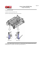
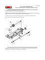
3.3.24 Cassette Guide L Assy
(1) Remove the paper cassette.
(2) Remove the upper cover (see 3.3.1).
(3) Remove the lower base unit (see 3.3.5).
(4) Remove the Main Control M5B-PCB (see 3.3.21).
(5) Remove the transformer (see 3.33.22).
(6) Remove the power supply/sensor board (see 3.3.23).
(7) Remove two screws (1), and remove the guide rails (2).
(8) Remove the screw (3), and remove the cassette guide L (9) by shifting it in the direction of the arrow as shown
below.
(9) Remove cassette lock lever (4) and torsion spring (5).
(10) Remove cassette lock lever spring (8) then remove the sheet link (L) (6) and Pull block (7).
Copyright 1998, Okidata, Division of OKI America, Inc. All rights reserved. See the OKIDATA Business Partner
Exchange (BPX) for any updates to this material. (http://bpx.okidata.com)
Page: 50
Service Guide OKIPAGE 10ex
Chapter 3 Disassembly
3.3.25 Cassette Guide R
(1) Remove the paper cassette.
(2) Remove the upper cover (see 3.3.1).
(3) Remove the lower base unit (see 3.3.5).
(4) Remove the Main Control M5B-PCB (see 3.3.21).
(5) Remove the two screws (1), and remove the guide rails (2).
(6) Remove the screw (3), and remove the cassette guide R (4) by shifting it in the direction of arrow.
(7) Remove the cassette lock lever (5) and torsion spring (6).
(8) Remove the cassette lock lever spring (9), then remove the sheet ink (R) (7) and link pull block (8).
(9) Remove two screws (10), and remove the square-shaped connector (11).
Copyright 1998, Okidata, Division of OKI America, Inc. All rights reserved. See the OKIDATA Business Partner
Exchange (BPX) for any updates to this material. (http://bpx.okidata.com)
Page: 51
Service Guide OKIPAGE 10ex
Chapter 3 Disassembly
3.3.26 Spacer Bearing (L/R)
(1) Remove the back-up roller (see 3.3.16).
(2) Remove spacer bearing (L/R) with a tip of screw driver.
Copyright 1998, Okidata, Division of OKI America, Inc. All rights reserved. See the OKIDATA Business Partner
Exchange (BPX) for any updates to this material. (http://bpx.okidata.com)
Page: 52
Service Guide OKIPAGE 10ex
Chapter 4 Adjustments
4. Adjustment
This chapter provides explanations concerning the adjustment necessary when replacing a part. The adjustment is
made by changing the parameter value set in EEPROM on the main control board. The parameter can be set by the key
operation from the operator panel. This printer has three kinds of maintenance modes, and it is necessary to select one
of the modes when replacing any parts.
Copyright 1998, Okidata, Division of OKI America, Inc. All rights reserved. See the OKIDATA Business Partner
Exchange (BPX) for any updates to this material. (http://bpx.okidata.com)
Page: 53
Service Guide OKIPAGE 10ex
Chapter 4 Adjustments
4.1 Maintenance Modes and Functions
4.1.1 User Maintenance Mode
4.1.2 System Maintenance Mode
4.1.3 Engine Maintenance Mode
4.1.4 EEPROM Initialization
Copyright 1998, Okidata, Division of OKI America, Inc. All rights reserved. See the OKIDATA Business Partner
Exchange (BPX) for any updates to this material. (http://bpx.okidata.com)
Page: 54
Service Guide OKIPAGE 10ex
Chapter 4 Adjustments
4.1.1 User Maintenance Mode
To enter into the user maintenance mode, turn the POWER switch on while holding the MENU key down.
Function
There are five functions as follows:
l
l
l
l
l
l
l
l
l
l
Menu reset
Opepane menu disable
Hex dump
X-adjust
Drum counter reset
Y-adjust
Receiove buffer
2nd Tray
Setting
Place page
Detailed descriptions of these functions are provided in Appendix D, DIAGNOSTICS TEST.
Copyright 1998, Okidata, Division of OKI America, Inc. All rights reserved. See the OKIDATA Business Partner
Exchange (BPX) for any updates to this material. (http://bpx.okidata.com)
Page: 55
Service Guide OKIPAGE 10ex
Chapter 4 Adjustments
4.1.2 System Maintenance Mode
This mode is used only by maintenance personnel and it should not be released to the end-users.
To enter into the system maintenance mode, turn the POWER switch on while holding the Recover key down.
Function
There are six functions as follows:
l
l
l
l
l
l
Page count display
Loop test
Page count printing enable/disable
EEPROM reset
Rolling ASCII continues printing
SIDM enable/ disable
Detailed descriptions of these functions are provided in Appendix D, DIAGNOSTICS TEST.
Copyright 1998, Okidata, Division of OKI America, Inc. All rights reserved. See the OKIDATA Business Partner
Exchange (BPX) for any updates to this material. (http://bpx.okidata.com)
Page: 56
Service Guide OKIPAGE 10ex
Chapter 4 Adjustments
4.1.3 Engine Maintenance Mode
Note: This mode is used only by maintenance personnel, and it should not be released to the end users.
(1) To enter into the engine maintenance mode, turn the power on while holding ENTER and FORM FEED keys down.
(2) Functions of this mode are selected by the menu.
(3) The way to exit out of this mode varies depending on the settings.
(4) There are following engine maintenance modes:
a) Head drive time setting - Sets the drive time of the LED head.
b) Head width setting - Sets the width of the LED head (39 or 40 chips).
c) Printing start position setting - Sets the starting position of printing.
d) Drum count total display - The total image drum rotation count of the printer, as counted by the engine section, is
displayed on the LCD.
e) Drum count display - The total image drum rotation count, as counted by the engine section, is displayed on the LCD.
f) Standard tray paper feeding quantity setting - Sets the amount of paper to be fed from the standard tray.
g) High Capacity Second Paper Feeder paper feeding quantity setting - Sets the amount of paper to be fed from High
Capacity Second Paper Feeder.
h) High Capacity Second Paper Feeder downloading table selection - Selects the downloading table of High Capacity
Second Paper Feeder.
i) Power Envelope Feeder paper feeding quantity setting - Sets the amount of paper to be fed from Power Envelope
Feeder.
j) Power Envelope Feeder downloading table selection - Selects the downloading table of Power Envelope Feeder.
k) Engine Reset - All EEPROM areas used by the engine section are reset to factory default values. The followings,
however, are not reset:
After reset, the printer returns to normal operating mode.
l
l
l
l
l
l
Menu Level-1
Menu Level-2
Operator Panel Menu Disable/Enable
LED HEAD No.
LED HEAD WID
Page Print Disable/Enable
Note: Please do re-set up LED Head type to "Type2D4" when the printer was done the engine reset operation by
manual or auto setting.
Because when it is done, the LED Head type is returned to the initial setting, which is "Type 1".
Application ROM (F/W Ver.1.01).
8174627N0011(MX23C2410MC-10-100 : IC3)
8174627N0012(MX23C2410MC-10-101 : IC2)
Note: "Printing start position setting" is for shipping. Do not change its default value.
Detailed descriptions of these functions are provided in Appendix D, DIAGNOSTICS TEST.
Copyright 1998, Okidata, Division of OKI America, Inc. All rights reserved. See the OKIDATA Business Partner
Exchange (BPX) for any updates to this material. (http://bpx.okidata.com)
Page: 57
Service Guide OKIPAGE 10ex
Chapter 4 Adjustments
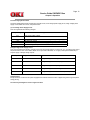
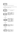
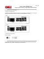
4.1.4 EEPROM Initialization
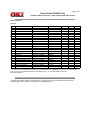
The corresponding are the EEPROM is initialized for each event as shown in Table 4-1.
No. EEPROM
Area
Menu
Level 1
Menu
Level 2
F/W
revision
area
Customer
Information
User
maintenan
ce area
Note1)
System
mainten
ance
area
Note1)
Engine Drum
Fuser
Page
mainten counter counter counter
ance
area
Note1)
1
User
O
maintenanc
e menu
reset
2
System
O
O
O
O
maintenanc
e EEPROM
reset
3
Engine
O
O
maintenanc
e engine
reset
4
Firm revision
O
O
O
O
O
check error
at power-on
5
Engine ID
O
O
check error
at power-on
6
Customer
O
O
O
O
O
setting
7
User
O
O
O
O
O
information
error
O = Represents initialization
Note1) Items of each maintenance menu which are subjects here are listed in the following table.
Note2) Only when the page counter is 500 sheets or less it is reset to 0.
Note2)
O
Table 4-1 Items of Each Maintenance Menu Targeted for EEPROM Reset
User maintenance menu area
System maintenance menu area
Engine maintenance menu area
Receiving buffer
SIDM emulation switch
enable/disable
Adjusting head type
(excluding during engine reset in
engine maintenance)
600 x 1200 DPI strobe time relative
value (excluding during engine reset
in engine maintenance)
Installed LED head identification
(excluding during engine reset in
engine maintenance)
Operator panel menu function
enable/disable
X / Y Adjust
2ND feed destination
Designated command
Left alignment based printing shift
Print start position
-----------------------------------------Paper feed amount from each paper
feed tray
Note2)
O
Cleaning cycle
Each optional tray motor controlling
parameter
---------------------------------------Engine test
Transfer current
(Only Engine ID check error at power
on Event)
Copyright 1998, Okidata, Division of OKI America, Inc. All rights reserved. See the OKIDATA Business Partner
Exchange (BPX) for any updates to this material. (http://bpx.okidata.com)
Page: 58
Service Guide OKIPAGE 10ex
Chapter 4 Adjustments
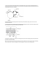
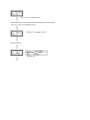
4.2 Adjustment When Replacing a Part
Adjustment is necessary when replacing any of the following parts.
Part Replaced
Adjustment
LED Head
Image Drum Cartridge
Main Control Board
Set the LED head drive time.
Reset the image drum counter (refer to User's Manual)
EEPROM data Upload / Download
Copyright 1998, Okidata, Division of OKI America, Inc. All rights reserved. See the OKIDATA Business Partner
Exchange (BPX) for any updates to this material. (http://bpx.okidata.com)
Page: 59
Service Guide OKIPAGE 10ex
Chapter 4 Adjustments
4.2.1 Setting of LED Head Drive Time
Note: When the luminous intensity marking of the replacement LED head (new part) is same as that of the removed
LED head (old part), do not reset the LED head drive time.
l
Luminous Intensity Marking Label
l
Setting of LED Head Drive Time
Drive time of the LED head is set by setting the parameter of drive time of EEPROM according to the luminous intensity
marking on the LED head.
a. Corresponding table of luminous intensity marking and drive time parameter
Luminous intensity marking on
LED head
(~ 020)
(021)
(022~ 024)
(025)
(026)
027 ~ 028
029 ~ 030
031 ~ 035
033 ~ 037
036 ~ 040
038 ~ 043
041 ~ 028
Drive time
parameter
32
31
30
29
28
27
26
25
24
23
22
21
Luminous intensity marking on
LED head
058 ~ 060
061 ~ 064
065 ~ 069
070 ~ 073
074 ~ 079
080 ~ 084
085 ~ 090
091 ~ 096
097 ~ 103
104 ~ 110
(111 ~ 118)
(119 ~ 126)
Drive time
parameter
16
15
14
13
12
11
10
9
8
7
6
5
044 ~ 028
047 ~ 028
050 ~ 028
053 ~ 028
20
19
18
17
(127 ~ 135)
(136 ~ 144)
(145 ~ 154)
(155 ~ )
4
3
2
1
* ( ) marking of the luminous intensity marking on LED head depend on the darkness control parameter.
b. Corresponding table of darkness setting and drive time parameter.
Procedure
Example: Method for setting the parameter to 19 (for case where the previous parameter setting was 21).
Setting of LED Head Drive Time (OKIPAGE 6ex)
Drive time of the LED head is set by setting the parameter of drive time of EEPROM according to the luminous intensity
marking on the LED head.
Luminous Intensity Marking and Drive Time Parameter Table
Luminous intensity marking on
LED head
Drive time
parameter
Luminous intensity marking on
LED head
Drive time parameter
027 ~ 028
029 ~ 030
031 ~ 032
033 ~ 035
036 ~ 037
27
26
25
24
23
065 ~ 069
070 ~ 073
074 ~ 079
080 ~ 084
085 ~ 090
14
13
12
11
10
038 ~ 040
041 ~ 043
044 ~ 046
047 ~ 049
050 ~ 052
053 ~ 057
058 ~ 060
061 ~ 064
22
21
20
19
18
17
16
15
091 ~ 096
097 ~ 103
104 ~ 110
111 ~ 118
119 ~ 126
127 ~ 135
136 ~ 144
145 ~ 154
9
8
7
6
5
4
3
2
* ( ) marking of the luminous intensity marking on LED head depend on the darkness control parameter.
b. Corresponding table of darkenss setting and drive time parameter
Darkness setting
-2
-1
0
+1
+2
Drive time parameter
-4
-2
0
+3
+6
* The drive time parameter of the LED head depend on the setting of the darkness control.
ex.: Luminous intensity marking on LED head : 027 ~ 028
Darkness setting : -2
Drive time parameter : 31 [27-(-41)]
c. Setting
Example: Method for setting the parameter to 19 (for a case where the previous parameter setting was 8).
Copyright 1998, Okidata, Division of OKI America, Inc. All rights reserved. See the OKIDATA Business Partner
Exchange (BPX) for any updates to this material. (http://bpx.okidata.com)
Page: 60
Service Guide OKIPAGE 10ex
Chapter 4 Adjustments
4.2.2 Uploading/Downloading EEPROM data
When the controller printed circuit board is replaced, the contents of the old EEPROM shall be copied to the new
EEPROM on the new board to preserve customer settings. For the purpose, use the EEPROM operation on the Option
of the Maintenance Utility. To copy follow the steps below.
(1) Be sure to confirm that the printer and the PC are connected with a centronics I/F cable. Then execute the
Maintenance Utility. (Note: Printer driver shall be deinstalled.)
(2) Select the Option on the Maintenance Utility.
(3) Click the "UPLOAD EEPROM" button on the "EEPROM Operations".
(4) The contents of the EEPROM data is displayed on the "DIALOG" of the Maintenance Utility. The contents of the old
EEPROM is now copied into the memory of the PC.
(5) Replace the controller P.C.B. with a new one while it displays the above "DIALOG".
(6) After the replacement, click "Download EEPROM" on the "EEPROM Operations". EEPROM upload has been
completed.
In case of troubles such as centronics I/F failure, etc. EEPROM data may not be uploaded properly. In such case, it is
necessary to adjust the following settings manually after the replacement using the Maintenance Utility.
l
l
LED driver time (See 4.2.1)
Factory setting (ODA/OEL/INT-A/INT-L)
The maintenance utility is designed to be used only by field engineer and it should not be released to the end-users.
Copyright 1998, Okidata, Division of OKI America, Inc. All rights reserved. See the OKIDATA Business Partner
Exchange (BPX) for any updates to this material. (http://bpx.okidata.com)
Page: 61
Service Guide OKIPAGE 10ex
Chapter 5 Maintenance
5.1 Periodical Replacement Parts
Part name
Toner cartridge (Type 5)
Condition for replacement
Cleaning
About 2,000 sheets of paper have LED head
been printed
Image drum cartridge (Type 5) About 20,000 sheets of paper have
been printed. See 1.4 (14)
Remarks
Consumables
Consumables
Copyright 1998, Okidata, Division of OKI America, Inc. All rights reserved. See the OKIDATA Business Partner
Exchange (BPX) for any updates to this material. (http://bpx.okidata.com)
Page: 62
Service Guide OKIPAGE 10ex
Chapter 5 Maintenance
5.2 Cleaning
Remove any toner or dust accumulated inside the printer. Clean in and around the printer with a piece of cloth when
necessary. Use the handy cleaner (service tool) to clean inside the printer.
Note: Do not touch the image drum, LED lens array, or LED head connector block.
5.2.1 Cleaning of LED Lens Array
5.2.2 Cleaning Page Function
Copyright 1998, Okidata, Division of OKI America, Inc. All rights reserved. See the OKIDATA Business Partner
Exchange (BPX) for any updates to this material. (http://bpx.okidata.com)
Page: 63
Service Guide OKIPAGE 10ex
Chapter 5 Maintenance
5.2.1 Cleaning of LED Lens Array
Clean the LED lens array or replace the toner cartridge when white lines or stripes (void, light printing) are generated
vertically down the page, as shown below.
Note: The LED lens array must be cleaned with an LED head cleaner included in the replacement toner kit.
(1) Set the LED head cleaner to the LED lens array as shown in the figure, then slide the cleaner back and forth
horizontally several times to clean the head.
Note: Gently press the LED head cleaner onto the LED lens array.
(2) Throw the cleaner pad away.
Copyright 1998, Okidata, Division of OKI America, Inc. All rights reserved. See the OKIDATA Business Partner
Exchange (BPX) for any updates to this material. (http://bpx.okidata.com)
Page: 64
Service Guide OKIPAGE 10ex
Chapter 5 Maintenance
5.2.2 Cleaning Page Function
There is a charge roller cleaning function with this printer, which can be executed by the user.
(1) While the printer is in off-line mode, press both
enters the cleaning mode.
and
keys simultaneously for at least 2 seconds. The printer
(2) The LCD displays "CLEANING" on the upper line, and on the lower line, "MANUAL LETTER REQUEST" is
displayed, scrolling one character width at a time from right to left "LETTER" on the lower line may instead be "A4"
depending on the printer designation. While the lower line scrolls the message, the message on the upper line remains
fixed in place. When the above messages appear on the LCD, the user can verify that the printer has entered the
cleaning mode and that it is requesting insertion of a letter (or A4) size paper into the manual feederslot.
(3) Insert a sheet of paper into the manual feeder slot.
(4) Toner attached to the image drum is transferred onto the inserted sheet, and the sheet is ejected with the toner
residues printed. While this process is going on, the LCD displays "PRINT CLEANING" message.
(5) The printer returns to off-line mode.
Copyright 1998, Okidata, Division of OKI America, Inc. All rights reserved. See the OKIDATA Business Partner
Exchange (BPX) for any updates to this material. (http://bpx.okidata.com)
Page: 65
Service Guide OKIPAGE 10ex
Chapter 6 Troubleshooting
6.1 Troubleshooting Tips
(1) Check the problem solving section in the Printer Handbook.
(2) Gather as much information about the situation as possible.
(3) Inspect the equipment under the conditions close to those in which the problem had occurred.
Copyright 1998, Okidata, Division of OKI America, Inc. All rights reserved. See the OKIDATA Business Partner
Exchange (BPX) for any updates to this material. (http://bpx.okidata.com)
Page: 66
Service Guide OKIPAGE 10ex
Chapter 6 Troubleshooting
6.2 Points to Check before Correcting Image Problems
(1) Is the printer being run in proper ambient conditions?
(2) Are supplies (toner) and routine replacement part (image drum cartridge) being replaced properly?
(3) Is the printing paper normal (acceptable quality)?
(4) Is the image drum cartridge being loaded properly?
Copyright 1998, Okidata, Division of OKI America, Inc. All rights reserved. See the OKIDATA Business Partner
Exchange (BPX) for any updates to this material. (http://bpx.okidata.com)
Page: 67
Service Guide OKIPAGE 10ex
Chapter 6 Troubleshooting
6.3 Tips for Correcting Image Problems
(1) Do not touch, or bring foreign matter into contact with the surface of the image drum.
(2) Do not expose the image drum to direct sunlight.
(3) Keep hands off the fuser unit as it heats up during operation.
(4) Do not expose the image drum to light for longer than 5 minutes at room temperature.
Copyright 1998, Okidata, Division of OKI America, Inc. All rights reserved. See the OKIDATA Business Partner
Exchange (BPX) for any updates to this material. (http://bpx.okidata.com)
Page: 68
Service Guide OKIPAGE 10ex
Chapter 6 Troubleshooting
6.4 Preparation for Troubleshooting
(1) Operator panel display
The failure status of the printer is displayed by the liquid crystal display (LCD) of the operator panel. Take proper
corrective action as directed by messages which are being displayed on the LCD.
Copyright 1998, Okidata, Division of OKI America, Inc. All rights reserved. See the OKIDATA Business Partner
Exchange (BPX) for any updates to this material. (http://bpx.okidata.com)
Page: 69
Service Guide OKIPAGE 10ex
Chapter 6 Troubleshooting
6.5 Troubleshooting Flow
Should there be a problem with the printer, carry out troubleshooting according to the following procedure flow:
6.5.1 LCD Status Message/Problem List
The status and problems which may be displayed by messages on the LCD are listed in Table 6-1.
6.5.2 LCD Message Troubleshooting
Copyright 1998, Okidata, Division of OKI America, Inc. All rights reserved. See the OKIDATA Business Partner
Exchange (BPX) for any updates to this material. (http://bpx.okidata.com)
Page: 70
Service Guide OKIPAGE 10ex
Chapter 6 Troubleshooting
6.5.1 LCD Status Message/Problem List
The status and problems which may be displayed by messages on the LCD are listed in Table 6-1.
Category
LCD status message Code (nn) Problem or Status
Error
Control errors
An error occurred in
the controller
1-3
D-F
4
5
6
7
8
9
A
B
C
10
20
30
40
50
Remedy
- Normal operation cannot be
ensured. Turn the power off, then
back on to restart.
- If normal operation is not
recovered by this restart procedure,
replace the main control board.
Reserved
Address Error
Exception
(Load command,
command fetch)
Address Error
Exception
(Store command)
Bus Error Exception
(Command fetch)
Bus Error Exception
(Load command,
store command)
System Call
Extension
Break Point
Exception
Reserved Instruction
Exception
Coprocessor
Unusable Exception
Arithmetic Overflow
Exception
An error occurred in
the controller.
An error was
detected by program
ROM check.
An error was
detected by font
ROM check.
An error was
detected by resident
RAM check.
An error was
detected by
EEPROM check.
An error was
detected by optional
software ROM check.
- Turn the power off, then back on
to recover from the error.
- If normal operation is not
recovered by this restart procedure,
use the following remedial actions.
Replace the main control board.
Replace the main control board.
Replace the main control board.
Replace the EEPROM or main
control board.
Check the optional software ROM
board for proper connection or
replace it.
51
60
61
70
71
72
73
74
77
F5
F6
F7
An error was
detected by Flash
SIMM.
An error was
detected by optional
RAM check.
Data bus Error
between COS and
Databus for Option
DRAMs.
A failure occurred
with the Fan motor.
A failure occurred
with the fuser
(timeout error etc).
A failure occurred
with the fuser
(thermistor open
error).
A failure occurred
with the fuser
(thermistor short
error).
SSIO Error
Check the optional Flash SIMM for
proper connection or replace it.
- Check the optional RAM board for
proper connection.
- Check the mounting position of
short plugs and additional RAM
chips (see Section 7.4).
- Replace the optional RAM board.
Check the optional DRAM SIMM for
proper connection or replace it.
- Check the fan motor for proper
connection and for any presence of
foreign matter in the fan (see
Section 6.5-2(6).
- Replace the fan or the main
control board.
See Section 6.5.2-(4).
See Section 6.5.2-(4).
See Section 6.5.2-(4).
- Check the connection between
the main control board and the
power supply/sensor board.
- Replace the main control board or
power supply/sensor board.
A toner sensor fault
- Check the installation of image
has occurred when
drum unit.
the TOTAL DRUM
- Replace the power supply/sensor
COUNT is 30 or less. board.
System timer
- Turn the power off, then back on
program error.
again.
Defect in the cable of - Repair or replace the defective
the front feeder paper front feeder paper sensor cable and
sensor and the 2-pin 2-pin connector on the main control
connector on the
board or reconnect the connectors.
main control board.
- Replace the main control board.
Poor connection of
connectors.
IPT2 program error
- Turn the power off, then back on
again.
- Replace the main control board.
IPT1 program error
- Turn the power off, then back on
again.
- Replace the main control board.
Interface errors
Category
LCD status
message
Problem or status
Remedy
Interface errors
Cover open
Cover open
Jam errors
Jam errors
Paper size error
Tray paper out
Size error
An error occurred in the serial
I/F. This message is displayed
when a parity error, a framing
error or an overrun error is
detected. (When an error
occurred in serial I/F0.
- Press the operator panel RECOVER key
to release the error display.
When serial I/F board has been installed:
- Check the settings related serial I/F of
the menu.
- Replace the serial I/F cable or main
control board.
The upper cover was opened. - Close the cover to release the error
display.
- If the display does not change after this
procedure, replace the power
supply/sensor board.
The High Capacity Second
- Close the cover to release the error
Paper Feeder option cover
display.
was opened.
- Check the connection between the
main control board and TQSB-2-PCB.
- Replace the main control board
TQSB-2-PCB or connector.
A jam occurred during paper - Check the paper in the cassette. Open
hopping from the tray.
and then close the cover. When the
cover is closed, recovery printing is
tray: TRAY1, TRAY2,
performed and the error display is
FEEDER, MANUAL
released.
- If this error occurs frequently, see
Section 6.5.2(2)-1.
A jam occurred during paper - Open the cover, remove the paper, then
feeding after completion of
close the cover. When the cover is
paper hopping from the tray. closed, recovery printing is performed
and the error displayed is released.
tray: TRAY1, TRAY2,
- If this error occurs frequently, see
FEEDER
Section 6.5.2 (2)-2.
Paper of improper size is
- Check the paper in the tray or check to
being fed from the tray.
see if more than one sheet of paper were
being fed simultaneously.
tray: TRAY1, TRAY2,
- Set the designated paper in the tray.
FEEDER
- Open the cover, then close it to perform
recovery printing and release the error
display.
- If this error occurs frequently, see
Section 6.5.2.(3).
The tray has run out of paper. Load paper in the tray.
tray: TRAY1, TRAY2,
FEEDER
Loading of paper indicated by Load the requested paper in the tray.
the first line message is
requested. The paper size
may be one of the followings:
Paper: LETTER, EXECUTIV,
LEGAL 14, LEGAL 13, A4
SIZE, A5 SIZE, A6 SIZE, B5
SIZE, COM-9, COM-10,
MONARCH, DL ENV, C5
ENV
Size error
Manual loading of paper
Load the requested paper in the tray.
indicated by the first line
message is requested. The
paper size may be one of the
followings:
LETTER, EXECUTIV,
LEGAL 14, LEGAL 13, A4
SIZE, A5 SIZE, A6 SIZE, B5
SIZE, FREE SIZE, COM-10,
MONARCH, DL ENV, C5
ENV
Buffer overflow
The receive buffer is
overflowing.
Buffer overflow
Buffer overflow
Daily status
Daily status
- Press the operator panel RECOVER key
on the operator panel to release the error
display.
- Change the setting of the host or printer
so that the host can detect the busy
status of the printer. Resend the data
from the host to the printer.
- Replace the interface cable or main
control board.
The page buffer is overflowing - Press the RECOVER key to release the
because it received too much error display.
data for printing on the page. - Install additional optional RAM board or
Macro buffer is overflowing.
reduce the print data.
The DLL buffer is overflowing.
The printer overrun because - Press the RECOVER key on the
the print data is too
operator panel to release the error
complicated to be printed.
display.
- Simplify page data formatting.
The printer is in the off-line
Normal operation.
mode. The second line
indicates the emulation.
emulate: AUTO, PCL, PPR,
FX, HEX
The printer is processing
data.
Normal operation.
Daily status
The printer is printing a page. Normal operation.
Daily status
The printer is processing data Normal operation.
in the on-line mode.
READY ON: The data that is
not printed remains in the
buffer.
Ready flashing: The printer is
receiving data or in printing
process.
Buffer overflow
emulate: AUTO, PCL, PPR,
FX, HEX
The receive buffer is
overflowing.
- Press the operator panel RECOVER key
on the operator panel to release the error
display.
- Change the setting of the host or printer
so that the host can detect the busy
status of the printer. Resend the data
from the host to the printer.
- Replace the interface cable or main
control board.
Buffer overflow
Buffer overflow
Daily status
Daily status
The page buffer is overflowing
because it received too much
data for printing on the page.
Macro buffer is overflowing.
The DLL buffer is overflowing.
The printer overrun because
the print data is too
complicated to be printed.
The printer is in the off-line
mode. The second line
indicates the emulation.
emulate: AUTO, PCL, PPR,
FX, HEX
The printer is processing
data.
- Press the RECOVER key to release the
error display.
- Install additional optional RAM board or
reduce the print data.
- Press the RECOVER key on the
operator panel to release the error
display.
- Simplify page data formatting.
Normal operation.
Normal operation.
Daily status
The printer is printing a page. Normal operation.
Daily status
The printer is processing data Normal operation.
in the on-line mode.
READY ON: The data that is
not printed remains in the
buffer.
Ready flashing: The printer is
receiving data or in printing
process.
Daily status
Daily status
Daily status
Daily status
Daily status
Daily status
emulate: AUTO, PCL, PPR,
FX, HEX
All fonts of the printer are
Normal operation.
being printed during self-test.
The current menu setting is
being printed.
Normal operation.
Ready ON: Executed by
command entry.
Ready flashing: Executed by
key operation.
Message displayed when the Normal operation
power is turned on. When the
power is turned on, the LEDs
are turned on for
approximately 1 second,
conducting a test to verify the
conditions of the LEDs and
LCD.
Message displayed to indicate Normal operation.
that the controller is
undergoing an initialization
when the power is turned on.
This message is displayed
after the turning on of the
LEDs as described above.
Indicates in Cold mode due to Normal operation.
downloading to flash memory.
Indicates that an error occurs Normal operation.
during downloading to flash
memory or deleting.
Daily status
Daily status
Daily status
Daily status
Daily status
Daily status
Daily status
Daily status
The demo page is being
printed:
Normal operation.
Ready LED on: Executed by
command entry.
Ready LED blinking:
Executed by key operation.
When the number of copies Normal operation.
being printed is two or more,
the number of copies being
printed is displayed. The
message is displayed together
with another message on the
first line.
nnn : Current page
mmm : Total page
This message is displayed
Normal operation.
when the printer is performing
the cleaning print.
Manual loading of paper
Normal operation.
indicated by the second line
message is being requested
for cleaning. The paper size
(#) may be one of the
following:
# : LETTER REQUEST, A4
SIZE REQUEST
The data which remained
unprinted in the buffer is
deleted and the printer is
initialized to user default
settings. The temporary DLLs,
macros and user pattern are
deleted.
This message is displayed
when the printer cannot reset
automatically to exit from the
menu because there are date
and DLL's and macros having
temporary attributes when the
printer is changed from set
mode to another mode.
Toner is running out. This
message is displayed together
with another message on the
first line. Normal operation
can be continued.
A fault occurred with the toner
sensor. This message is
displayed together with
another message on the first
line. Normal operation can be
continued.
Normal operation.
Normal operation.
Replace the toner cartridge.
Replace the power supply/sensor board.
Daily status
Daily status
Daily status
Daily status
Daily status
Daily status
Displays that the amount of
toner is near empty (this
status will appear after 100
sheets from a TONER LOW
indication). It is indicated by
being combined with other
messages in the first line.
Normal operation can be
continued.
Displays that the amount of
toner is near empty. After 100
sheets from a TONER LOW
indication, this status will
appear and the printing will
stop. If pressing ON-LINE
SW, another 31 sheets can
be printed and stopped. And
from the next time on, the
printing is stopped after each
sheet.
The printer is in the
Normal operation.
power-saving mode. This
message is displayed together
with another message on the
first line.
Informs drum life end. It can
be temporarily released by
opening and closing the cover
or pressing the "ON LINE"
switch, but basically, the drum
must be replaced.
Indicates an error from the
result of checking EEPROM
ID No. The printer will display
this for a few seconds and
reset the EEPROM to the
factory default for a
continuous operation. It will
occur with a new EEPROM.
Reformat error including
CPCMCIA HEADER or
ROM-SIMM and byte sum. It
will be displayed for 2
seconds at power-on or just
before a shift to ON LINE.
Copyright 1998, Okidata, Division of OKI America, Inc. All rights reserved. See the OKIDATA Business Partner
Exchange (BPX) for any updates to this material. (http://bpx.okidata.com)
Page: 71
Service Guide OKIPAGE 10ex
Chapter 6 Troubleshooting
6.5.2 LCD Message Troubleshooting
If the problems cannot be corrected by using the LCD status message/problem list, follow the troubleshooting flowcharts
given here to deal with them.
No.
1.
2.
3.
4.
5.
6.
Trouble
The printer does not work normally after the power
is turned on.
Jam alarm
l Paper input jam
l Paper feed jam
l Paper exit jam
Paper size error
Fusing unit error
SSIO (Synchronous Serial Input/Output) error I/F timeout (no
response) between the printer and an optional tray (High Capacity
Second Paper Feeder, Power Envelope Feeder).
Fan error
Flowchart number
(1)
(2) - 1
(2) - 2
(2) - 3
(3)
(4)
(5)
(6)
Copyright 1998, Okidata, Division of OKI America, Inc. All rights reserved. See the OKIDATA Business Partner
Exchange (BPX) for any updates to this material. (http://bpx.okidata.com)
Page: 72
Service Guide OKIPAGE 10ex
Chapter 6 Troubleshooting
(1) The printer does not work normally after the power is turned on.
l
Turn the power off, then back on.
l
Is all black message being displayed by the LCD display?
l
No - Is the AC cord being connected properly?
l
l
No - Connect the AC cord properly.
Yes - Is +5 V being applied between Pins 11 and 21 of POWER connector on the main control board?
Pin 21 : 0 V
Pin 11 : +5 V
(A)
l
No - Is the connection between POWER connector on the main control board and connector
CN3 on the power supply/sensor board being made properly?
No - Correct the connection.
l
Yes - Go to 1-1.
l
Yes - Is +8 V being applied between Pins 23 and 24 (GND) of POWER connector?
Pin 23 : 0 V
Pin 24 : +8 V
l
l
Yes - Is the flexible cable for the operator panel assy being connected to the PANEL connector on the
control board and the connector CN1 on the OLCC board properly?
l
l
No - Connect the flexible cable properly.
Yes - Replace the operator panel assy or flexible cable.
l
Has the problem been solved?
l
l
l
No - Replace the main control board.
Yes - End
Yes - Is INITIALIZING message being displayed by the LCD display?
l
l
No - Go to A
No - Replace the main control board.
Yes - Is ON-LINE XXX message being displayed by the LCD display?
DUMP, PPR, FX
l
XXX: PCL, Auto, Adobe PS, HEX
No - Take actions according to the LCD status message/problem list (see Section 6.5.1 for corrective actions).
l
Yes - End
(1)-1
l
Take the measurement of the following voltage readings at connector CN2 on the power supply/sensor board:
Voltage between Pins 1 and 3: ... about 40 V AC
Voltage between Pins 5 and 6: ... about 9.2 V AC
Are the voltages within the normal range?
l
Yes - Is fuse F3 on the power supply/sensor board blown?
l
l
l
Yes - Replace the AC transformer.
No - Is fuse F1 or F2 on the power supply/sensor board blown?
l
l
Yes - Replace fuse F3 (if it blows again, check the resistance of the registration and main/drum motors. If it
is faulty, replace motors or replace the power supply/sensor board or main control board).
No - Is the AC input voltage output between Pins 1 and 2 of connector CN1 on the power supply/sensor board
normal?
l
l
No - Replace the power supply/sensor board.
No - Replace the power supply/sensor board.
Yes - Replace blown fuse F1 or F2 (if is blows again, replace the power supply/sensor board).
Figure 6-1 Low-voltage Power Supply Block Diagram
Copyright 1998, Okidata, Division of OKI America, Inc. All rights reserved. See the OKIDATA Business Partner
Exchange (BPX) for any updates to this material. (http://bpx.okidata.com)
Page: 73
Service Guide OKIPAGE 10ex
Chapter 6 Troubleshooting
(2) [JAM error]
Paper input jam
Paper feed jam
Paper exit jam
Copyright 1998, Okidata, Division of OKI America, Inc. All rights reserved. See the OKIDATA Business Partner
Exchange (BPX) for any updates to this material. (http://bpx.okidata.com)
Page: 74
Service Guide OKIPAGE 10ex
Chapter 6 Troubleshooting
Paper input jam
l
Does the JAM error occur when the power is turned on?
l
Yes - Is the paper at the inlet sensor?
l
l
No - Is the operation of the inlet sensor plate normal (moves freely when it is touched)?
l
l
l
Yes - Remove the paper.
No - Replace the inlet sensor plate.
Yes - Clean the inlet sensor on the power supply/sensor board, or replace the power supply/sensor board.
No - Does the JAM alarm occur after paper feeding?
l
Yes - Is the paper fed to the inlet sensor plate?
l
Yes - Is the operation of the input sensor plate normal (moves freely when it is touched)?
l
l
l
l
Yes - Replace the one-way clutch gear of the hopping roller assembly.
No - Connect RM connector properly.
Yes - Is the coil resistance (normal resistance: both between Pins 1 and 2, as well as Pins 3 and 4 are about 18.6
W) of the registration motor normal?
l
l
Yes - Set the paper tray properly.
No - Is RM connector on the main control board being connected properly?
l
l
No - Replace the hopping roller rubber or paper cassette.
No - Is the registration motor rotating?
l
l
Yes - Clean the inlet sensor on the power supply/sensor board or replace the power supply/sensor board.
No - Is the hopping roller rotating?
l
l
No - Replace the inlet sensor plate.
No - Replace the registration motor.
Yes - Replace the main control board.
Copyright 1998, Okidata, Division of OKI America, Inc. All rights reserved. See the OKIDATA Business Partner
Exchange (BPX) for any updates to this material. (http://bpx.okidata.com)
Page: 75
Service Guide OKIPAGE 10ex
Chapter 6 Troubleshooting
Paper feed jam
l
Does the paper feed jam occur when the power is turned on?
l
Yes - Is the paper on the paper sensor plate?
l
l
No - Is the operation of the paper sensor plate normal (moves freely when it is touched)?
l
l
l
Yes - Replace the power supply/sensor board.
No - Is the registration roller rotating?
l
l
l
No - Set the image drum cartridge properly.
Yes - Check the hopping roller assembly or tray.
Yes - Has the paper reached the outlet sensor plate?
l
Yes - Is the operation of the outlet sensor plate normal (moves freely when it is touched)?
l
l
No - Replace the outlet sensor plate.
Yes - Clean the outlet sensor on the power supply/sensor board or replace the power supply/sensor board.
No - Is the main/drum motor rotating?
l
No - Is DM connector on the main control board being connected properly?
l
l
l
No - Connect DM connector properly.
Yes - Is the coil resistance (normal resistance: both between Pins l and 2, as well as Pins 3 and 4 are about
2.9W) of the main/drum motor correct ?
l
l
No - Replace the one-way clutch gear of the hopping roller assembly.
Yes - Is the image drum cartridge being set properly?
l
l
No - Replace the paper sensor plate.
No - Has the paper reached the paper sensor plate?
l
l
Yes - Remove the paper.
No - Replace the main/drum motor.
Yes - Replace the main control board.
Yes - Is the transfer roller rotating?
(2)-2-a
l
l
No Check the gears (transfer roller gear, idle gear and reduction gear).
Yes Is the fusing unit being installed properly?
l
No Install the fusing unit properly.
l
Yes Is the image drum cartridge being set properly?
l
l
No Set the image drum cartridge properly.
Yes Clean the paper sensor on the power supply/sensor board or replace the power supply/sensor board.
Copyright 1998, Okidata, Division of OKI America, Inc. All rights reserved. See the OKIDATA Business Partner
Exchange (BPX) for any updates to this material. (http://bpx.okidata.com)
Page: 76
Service Guide OKIPAGE 10ex
Chapter 6 Troubleshooting
Paper exit jam
l
Does the paper exit jam error occur when the power is turned on?
l
Yes - Is the paper on the outlet sensor plate?
l
l
No - In the operation of the outlet sensor plate normal (moves freely when it is touched)?
l
l
l
No - Pull the face-up stacker out of the printer completely or push it into the printer completely.
No - Install the eject roller assembly properly.
Yes - Has the coil spring come off the eject roller assembly?
l
l
Yes - Clean the outlet sensor on the power supply/sensor board or replace the power supply/sensor board.
Yes - Is the eject roller assembly being installed properly?
l
l
No - Replace the outlet sensor plate.
No - Is the face-up stacker pulled out completely from the printer or, pushed into the printer completely?
l
l
Yes - Remove the paper.
Yes - Install the coil spring to the eject roller assembly.
No - Replace the eject roller assembly.
Copyright 1998, Okidata, Division of OKI America, Inc. All rights reserved. See the OKIDATA Business Partner
Exchange (BPX) for any updates to this material. (http://bpx.okidata.com)
Page: 77
Service Guide OKIPAGE 10ex
Chapter 6 Troubleshooting
(3) Paper size error
l
Is paper of the specified size being used?
l
l
Yes Are inlet sensor plates 1 and 2 operating properly (moves freely when they are touched)?
l
l
No Replace the inlet sensor plate or clean the inlet sensor on the power supply/sensor board.
Yes Does the outlet sensor plate operate properly (moves freely when it is touched)?
l
l
No Use paper of the specified size.
No Replace the outlet sensor plate or clean the outlet sensor on the power supply/sensor board.
Yes Replace the power supply/sensor board.
Copyright 1998, Okidata, Division of OKI America, Inc. All rights reserved. See the OKIDATA Business Partner
Exchange (BPX) for any updates to this material. (http://bpx.okidata.com)
Page: 78
Service Guide OKIPAGE 10ex
Chapter 6 Troubleshooting
(4) Fusing unit error (ERROR 71) (ERROR 72) (ERROR 73)
l
Turn the power off, then back on again.
l
Yes - Is the thermistor open or shorted? Measure the resistance between thermistor contacts (heater contacts
120V/3W or 240V/10W, and thermistor contacts 220K Ohms at room temperature) (see Figure 6-2 below or
Section 7.3).
l
l
No - Do the thermistor contacts touch the contact assembly properly when the fusing unit is mounted in the printer?
l
l
Yes - Check the thermistor contacts or replace the main control board or the fusing unit.
No - Is the AC voltage being supplied to the contacts for the heater of the contact assembly? (see Figure 6-2 below)
l
l
No - Adjust the contacts of the contact assembly.
Yes - Is the heater of the fusing unit turned on (when the heater is turned on, light is emitted)?
l
l
Yes - Replace the fusing unit.
No - Replace the main control board or the power supply/sensor board.
Yes - Check the heat contacts of the fusing unit and the contact assembly for poor contact (see Figure 6-4 contact
(G) ).
Figure 6-2
Copyright 1998, Okidata, Division of OKI America, Inc. All rights reserved. See the OKIDATA Business Partner
Exchange (BPX) for any updates to this material. (http://bpx.okidata.com)
Page: 79
Service Guide OKIPAGE 10ex
Chapter 6 Troubleshooting
(5) SSIO error (ERROR 74)
Synchronous Serial I/O (ERROR 74) or I/F timeout between printer and optional tray (ERROR 81)
l
Is an option tray (High Capacity Second Paper Feeder or Power Envelope Feeder) being used?
l
Yes - Is the cable between the main control board and the optional tray being connected properly?
l
No - Connect the cable properly.
l
Yes - Replace the main control board.
l
Has the problem been solved?
l
l
No - Check the problem by following the High Capacity Second Paper Feeder maintenance manual of
Appendix F.
Yes - End
l
No - Replace the main control board.
l
Has the problem been solved?
l
l
No - Replace the power supply/sensor board.
Yes - End
Copyright 1998, Okidata, Division of OKI America, Inc. All rights reserved. See the OKIDATA Business Partner
Exchange (BPX) for any updates to this material. (http://bpx.okidata.com)
Page: 80
Service Guide OKIPAGE 10ex
Chapter 6 Troubleshooting
(6) Fan error (ERROR 70)
l
Is the fan rotating?
l
l
No - Is FAN connector on the main control board being connected properly?
l
l
Yes - Replace the main control board.
No - Connect FAN connector properly.
Yes - Replace the fan or main control board.
Copyright 1998, Okidata, Division of OKI America, Inc. All rights reserved. See the OKIDATA Business Partner
Exchange (BPX) for any updates to this material. (http://bpx.okidata.com)
Page: 81
Service Guide OKIPAGE 10ex
Chapter 6 Troubleshooting
6.5.3 Image Troubleshooting
Procedures for troubleshooting for the cases of abnormal image printouts are explained below. Figure 6-3 below shows
typical abnormal images.
Flowchart number
Problem
Images are light or blurred entirely (Figure 6-3, A )
Dark background density (Figure 6-3, B )
Blank paper is output (Figure 6-3, C )
Vertical block belt/black stripe (Figure 6-3, D )
Cyclical defect (Figure 6-3, E )
Print void
Poor fusing (images are blurred or peeled off when touched by hands)
Vertical white belt/white stripe (Figure 6-3, F )
(1)
(2)
(3)
(4)
(5)
(6)
(7)
(8)
A Light or blurred images entirely
B Dark background density
C Blank paper
D Black vertical stripes
E Cyclical defect
F White vertical belts
or streaks
Figure 6-3 Image Problems
Copyright 1998, Okidata, Division of OKI America, Inc. All rights reserved. See the OKIDATA Business Partner
Exchange (BPX) for any updates to this material. (http://bpx.okidata.com)
Page: 82
Service Guide OKIPAGE 10ex
Chapter 6 Troubleshooting
(1) Images are light or blurred entirely
Is the toner low? (Is the "Toner Low" being displayed?)
Yes - Supply toner.
No - Is paper of the specified grade being used?
No - Use paper of the specified grade.
Yes - Is the lens of the LED head dirty?
Yes - Clean the lens.
No - Is the LED head installed properly (check the HEAD1 and HEAD2 connectors of the main control board and PC
connector on the LED head for proper connection)?
No - Install the LED head properly.
Yes - Is the contact plate of the transfer roller in contact with the contact assembly of the power supply/sensor board
properly (see Figure 6-5)?
No - Adjust the contact plate of the transfer roller to make a proper contact with the power supply/sensor board and
shaft of the transfer roller.
Yes - Are the contact of the developing roller and the contact of the toner supply roller of the image drum cartridge in
contact with the contact assembly properly (see Figure 6-4 (A) and (B)?
No - Adjust the contacts of the developing and toner supply to make a proper contact with the contact
assembly.
Yes - Replace the transfer roller.
No - Has the problem been solved?
Yes - End
No - Replace the image drum cartridge.
Has this problem been resolved?
Yes - End
Note: After replacing the image drum cartridge, set the printer in the user maintenance mode by turning the
power on while pressing the MENU key and reset the drum counter (see Printer Handbook).
No - Is the tension between the back-up roller (7.52kg) and the surface of the back-up roller normal?
No - Replace the back-up roller or bias spring.
Yes - Replace the main control board or power supply/sensor board.
Copyright 1998, Okidata, Division of OKI America, Inc. All rights reserved. See the OKIDATA Business Partner
Exchange (BPX) for any updates to this material. (http://bpx.okidata.com)
Page: 83
Service Guide OKIPAGE 10ex
Chapter 6 Troubleshooting
(2) Dark background density
Has the image drum been exposed to external light?
Yes - Install the image drum in the printer and wait about 30 minutes.
No - Perform the cleaning page function (see Section 5.2.2).
Has the problem been solved?
Yes - End
No - Is the heat roller of the fusing unit dirty?
Yes - Clean the heat roller.
No - Is the contact of the cleaning roller of the image drum cartridge in contact with the contact assembly properly (see
Figure 6-4 (C)?
No - Adjust the contact of the cleaning roller to make a proper contact with the contact assembly.
Yes - Replace the image drum cartridge.
Has the problem been solved?
Yes - End
Note: After replacing the image drum cartridge, set the printer to the user maintenance mode by turning the power on
while pressing the MENU key, and reset the drum counter (see Printer Handbook).
No - Replace the main control board or power supply/sensor board.
Copyright 1998, Okidata, Division of OKI America, Inc. All rights reserved. See the OKIDATA Business Partner
Exchange (BPX) for any updates to this material. (http://bpx.okidata.com)
Page: 84
Service Guide OKIPAGE 10ex
Chapter 6 Troubleshooting
(3) Blank paper is output
Is the LED head being connected properly (check the HEAD1 and HEAD2 connectors on the main control board and
PC connector on the LED head)?
No - Connect the LED head properly or replace the head cable(s).
Yes - Is the contact of the image drum cartridge in the proper contact with the ground contact properly (see Figure 6-4
(c)?
No - Adjust the ground contact (Drum) of the contact assembly.
Yes - Replace the LED head.
Has this problem been solved?
Yes - End
Note: After replacing the LED head, set the printer to the engine maintenance mode by turning the power on
while pressing the FORM FEED and ENTER keys. Set the LED head drive time (see 4.2.1).
No - Replace the main control board or power supply/sensor board.
Copyright 1998, Okidata, Division of OKI America, Inc. All rights reserved. See the OKIDATA Business Partner
Exchange (BPX) for any updates to this material. (http://bpx.okidata.com)
Page: 85
Service Guide OKIPAGE 10ex
Chapter 6 Troubleshooting
(4) Black vertical belts or stripes
Performing the cleaning page function (see Section 5.2.2).
Has this problem been solved?
Yes - End
No - Replace the image drum cartridge.
Has this problem been solved?
Yes - End
Note: After replacing the image drum cartridge, set the printer to the user maintenance mode by turning the
power on while pressing the MENU key, and reset the drum counter (see Printer Handbook).
Clean the LED lens array of the LED head.
Has the problem been solved?
Yes - End
No - Replace the LED head.
Has the problem been solved?
Yes - End
Note: After replacing the LED head, set the printer to the engine maintenance mode by turning the power on
while pressing the FORM FEED and ENTER keys. Set the LED head drive time (see 4.2.1).
No - Replace the main control board or power supply/sensor board.
Copyright 1998, Okidata, Division of OKI America, Inc. All rights reserved. See the OKIDATA Business Partner
Exchange (BPX) for any updates to this material. (http://bpx.okidata.com)
Page: 86
Service Guide OKIPAGE 10ex
Chapter 6 Troubleshooting
(5) Cyclical defect
Image Drum
Developing roller
Toner supply roller
Charging roller
Cleaning roller
Transfer roller
Heat roller
Back-up roller
Frequency
Remedy
3.71" (94.2mm)
1.86" (47.12mm)
2.96" (75.27mm)
1.21" (30.63mm)
0.93" (23.56mm)
1.95" (49.6mm)
2.44" (62.0mm)
2.73" (69.4mm)
Clean or replace the image drum unit.
Replace the image drum unit.
Replace the image drum unit.
Replace the image drum unit.
Replace the image drum unit.
Replace the image drum unit.
Replace the heat roller.
Replace back-up roller.
Note: After replacing the image drum cartridge, set the printer to the user maintenance mode by turning the power on
while pressing the MENU key, and reset the drum counter (see Printer Handbook).
Copyright 1998, Okidata, Division of OKI America, Inc. All rights reserved. See the OKIDATA Business Partner
Exchange (BPX) for any updates to this material. (http://bpx.okidata.com)
Page: 87
Service Guide OKIPAGE 10ex
Chapter 6 Troubleshooting
(6) Prints voids
Is the contact plate of the transfer roller in proper contact with the power supply/sensor board. (See Figure 6-5.
No - Adjust the contact plate so that it touches the power supply/sensor board and the shaft of the transfer roller
properly.
Yes - Replace the transfer roller.
Has this problem been solved?
Yes - End
No - Is the tension between the back-up roller (7.52kg) and the surface of back-up roller normal?
No - Replace the back-up roller or bias spring.
Yes - Are the contacts of the toner supply roller, developing roller, image drum and charging roller in proper contact with
the contact assy (see Figure 6-4 (A), (B), (C), (D), (E)?
No - Adjust the contact so that they touch the contact assy properly.
Yes - Replace the image drum cartridge.
Has this problem been solved?
Yes - End
Note: After replacing the image drum cartridge, set the printer to the user maintenance mode by turning the power on
while pressing the MENU key, and reset the drum counter (see Printer Handbook).
No - Is the LED head installed properly (check the HEAD1 and HEAD2 connectors the main control board and PC
Connector on the LED head)?
No - Install the LED head properly.
Yes - Replace the LED head or the head cable(s).
Has this problem been solved?
Yes - End
Note: After replacing the LED head, set the printer to the engine maintenance mode by turning the power on
while pressing the FORM FEED and ENTER keys. Set the LED head drive time (see 4.2.1).
No - Replace the main control board or power supply/sensor board.
Copyright 1998, Okidata, Division of OKI America, Inc. All rights reserved. See the OKIDATA Business Partner
Exchange (BPX) for any updates to this material. (http://bpx.okidata.com)
Page: 88
Service Guide OKIPAGE 10ex
Chapter 6 Troubleshooting
(7) Poor fusing
Poor fusing (images are blurred or peels off when the printed characters and images on the paper are touched by
hand)
Is paper of the specified grade being used?
No - Use paper of the specified grade.
Yes - Is the tension between the back-up roller (7.52kg) and the surface of the back-up roller normal?
No - Replace the back-up roller bias spring.
Yes - Is the contact of the fusing unit assy in proper contact with the contact assy (see Figure 6-4 (G)?
No - Adjust the contact of the fusing unit assy to make a proper contact with the contact assembly.
Yes - Replace the fusing unit assy.
Has this problem been solved?
Yes - End
No - Replace the main control board or power supply/sensor board.
Copyright 1998, Okidata, Division of OKI America, Inc. All rights reserved. See the OKIDATA Business Partner
Exchange (BPX) for any updates to this material. (http://bpx.okidata.com)
Page: 89
Service Guide OKIPAGE 10ex
Chapter 6 Troubleshooting
(8) Vertical belts or streaks
Are the LED lens dirty?
Yes - Clean the LED lens.
No - Is the contact plate of the transfer roller in proper contact with the power supply/sensor board? (See Figure 6-5 (E).
No - Adjust the contact plate to make a proper contact with the power supply/sensor board.
Yes - Replace the transfer roller.
Has this problem been solved?
Yes - End
No - Is the tension between the back-up roller (7.52 kg) and the surface of back-up roller normal?
No - Replace the back-up roller or bias spring.
Yes - Is the LED head being installed properly (check HEAD1 and HEAD2 connectors on the main control board and
PC connector on the LED head?
No - Install the LED head.
Yes - Replace the LED head.
Has the problem been solved?
Yes - End
Note: After replacing the LED head, set the printer to the engine maintenance mode by turning the power
on while pressing the FORM FEED and ENTER keys. Set the LED head drive time (see 4.2.1).
Yes - Replace the image drum cartridge.
Has this problem been solved?
Yes - End
Note: After replacing the image drum cartridge, set the printer to the user maintenance mode by turning the
power on while pressing the MENU key. Reset the drum counter (see Printer Handbook).
No - Replace the main control board or power supply/sensor board.
Copyright 1998, Okidata, Division of OKI America, Inc. All rights reserved. See the OKIDATA Business Partner
Exchange (BPX) for any updates to this material. (http://bpx.okidata.com)
Page: 90
Service Guide OKIPAGE 10ex
Chapter 6 Troubleshooting
Figure 6-4
Copyright 1998, Okidata, Division of OKI America, Inc. All rights reserved. See the OKIDATA Business Partner
Exchange (BPX) for any updates to this material. (http://bpx.okidata.com)
Page: 91
Service Guide OKIPAGE 10ex
Chapter 6 Troubleshooting
Figure 6-5
Copyright 1998, Okidata, Division of OKI America, Inc. All rights reserved. See the OKIDATA Business Partner
Exchange (BPX) for any updates to this material. (http://bpx.okidata.com)
Page: 92
Service Guide OKIPAGE 10ex
Chapter 7 Wiring Diagram
7.1 Interconnect Signal Diagram
Copyright 1998, Okidata, Division of OKI America, Inc. All rights reserved. See the OKIDATA Business Partner
Exchange (BPX) for any updates to this material. (http://bpx.okidata.com)
Page: 93
Service Guide OKIPAGE 10ex
Chapter 7 Wiring Diagram
7.2 PCB Layout and Connector Signal List
(1) Main Control Board (M5B-PCB)
(2) Power Supply Board
FAN Connector Pin Assignment (To fan motor)
Opening
1
2
PIN NO.
I/O
Signal
Description
1
2
O
C
FANPOW
OV
Power supply for fan driving
Ground
3
3
I
FANALM-N
Fan alarm
DM Connector Pin Assignment (To main/drum motor)
Opening
PIN NO.
I/O
Signal
Description
1
2
3
4
O
O
O
O
DMPH1-N
DMPH1-P
DMPH2-N
DMPH2-P
Coil 1-N
Coil 1-P
Coil 2-N
Coil 2-P
1
2
3
4
Excitation sequence
Pin No.
Step No.
1
Line Color
2
4
1
3
Yellow
Black
Orange
Brown
Step No.
2
+
+
-
Step No.
3
+
+
-
+
+
Step No.
4
+
+
Turning direction Clockwise when viewed from the output axis.
RM Connector Pin Assignment (To registration motor)
Opening
PIN NO.
1
2
3
4
1
2
3
4
I/O
O
O
O
O
Signal
Description
RMPH1-N
RMPH1-P
RMPH2-N
RMPH2-P
Coil 1-N
Coil 1-P
Coil 2-N
Coil 2-P
Excitation sequence
PIN NO.
Line Color
Step No. Step No. Step No.
1
2
2
Yellow
+
4
Black
+
+
1
Orange
+
3
Brown
Rotary direction - Clockwise viewed from the output axis.
Head1 Connector Pin Assignment (To LED Head)
I/O
Signal
PIN NO.
1
2
3
4
5
6
7
8
9
10
11
12
13
14
O: Out
C: Common
C
O
C
O
O
C
O
O
O
O
O
O
O
O
0VLOGIC
HDCLK-P
0VLOGIC
HDD2-P
HDD3-P
0VLED
HDD0-P
HDD1-P
+3.3V
HDDLD-P
HDSTB1-N
HDSTB2-N
HDSTB3-N
HDSTB4-N
3
+
+
Step
No.
4
+
+
Description
Ground for logic
Clock
Ground for logic
Data 4
Data 3
Ground for LED
Data 0
Data 1
+3.3V power supply for LED driving
Load
Strobe 1
Strobe 2
Strobe 3
Strobe 4
HEAD2 Connector Pin Assignment (To LED head)
HEAD1
HEAD1
1
2
3
4
5
6
7
8
9
10
11
12
PIN NO.
I/O
1
2
3
4
5
6
7
8
9
10
11
12
SIGNAL
O
O
O
O
C
O
C
C
C
C
C
C
DESCRIPTION
+3.3V
+3.3V
+3.3V
+3.3V
+3.3V
+3.3V
0VLED
0VLED
0VLED
0VLED
0VLED
0VLED
+3.3V power supply for LED driving
+3.3V power supply for LED driving
+3.3V power supply for LED driving
+3.3V power supply for LED driving
+3.3V power supply for LED driving
+3.3V power supply for LED driving
Ground for LED
Ground for LED
Ground for LED
Ground for LED
Ground for LED
Ground for LED
O: Out
C: Common
PANEL Connector Pin Assignment (To operator panel)
HEAD2
HEAD2
1
2
3
4
5
6
PIN NO.
I/O
1
2
3
4
5
6
SIGNAL
O
C
O
I
C
O
DESCRIPTION
PLD-N
OV
PDATAOUT-P
PDATAIN-P
5V
PSCLK-N
Load
Logic ground
Data output
Data input
+5V power supply
Clock
I: In
O: Out
C: Common
ENVELOPE Connector Pin Assignment (To option feeder I/F)
PIN NO.
5
2
1
3
8
7
4
6
1
2
3
4
5
6
7
8
I/O
O
O
O
I
C
O
C
O
Signal
Description
PAPERIN-N
OPTSCLK-N
DATA-N
PAPERIN-N
OVP
38V
0V
5V
Paper sense 1
Clock
Data
OPT send data ready
Analog ground
+30V power supply
Logic ground
+5V power supply
I: In
O: Out
C: Common
2ND TRAY Connector Pin Assignment (To option tray I/F)
PIN NO.
1
2
3
4
5
6
7
8
1
2
3
4
5
6
7
8
I/O
Signal
Description
O
O
O
I
C
O
C
O
PAPERIN-N
OPTSCLK-N
DATA-N
PAPERIN-N
OVP
38V
0V
5V
Paper sense 1
Clock
Data
OPT send data ready
Analog ground
+30V power supply
Logic ground
+5V power supply
POWER Connector Pin Assignment (To power supply/sensor board)
Pin
No.
Signal
I/O
Description
Pin
No.
Signal
I/O* Description
2
1
2
TRSEL1
O
TR control switch
1
SQCR-N
I
4
3
4
THERM-CMP
I
Heater temperature 3
SCLK-N
I
6
8
10
12
5
7
9
11
6
8
10
12
CVOPN-N
DOUT-P
RXD2-P
+5V
I
O
I
I
5
7
9
11
PSIN1-N
WRSNS
OVL
+5V
I
I
C
I
14
13
14
+3.3V
I
13
+3.3V
I
16
18
15
17
16
18
OVL
+38V
C
I
15
17
OVL
+38V
C
I
20
22
19
21
20
22
HEATON-N
-8V
O
I
19
21
TRSEL2
OVP
O
C
24
23
24
+8V
I
23
OVP
C
Analog
TRSEL3-N
O
Cover open (+35V)
Serial data output
Serial data input
Logic circuit supply
voltage
LED head supply
voltage
Logic ground
Motor and fan drive
voltage and source
voltage for high
voltage supply
Heater on
RS232C line
voltage
RS232C line
voltage
TR control switch
Sequence clear signal
of serial I/F
Clock signal of serial
I/F
Paper sense
Reading of paper edge
Ground for logic
Logic circuit supply
voltage
LED head supply
voltage
Logic ground
Motor and fan drive
voltage and source
voltage for high voltage
supply
TR control switch
Analog
25
OVP
C
Analog
26
25
26
O: Out
I: In
C: Common
CENT Connector Pin Assignment (To Centro parallel I/F)
1
2
3
4
5
6
7
8
9
10
11
12
13
14
15
16
17
18
19
20
21
22
23
24
25
26
27
28
29
30
31
32
33
34
35
36
Pin
No.
I/O*
Signal
Description
Pin
No.
I/O
Signal
Description
1
2
3
4
5
6
7
8
9
10
11
12
13
14
15
16
17
18
I
C
C
C
C
C
C
C
C
O
O
O
O
I
Strobe
DATA1-P
DATA2-P
DATA3-P
DATA4-P
DATA5-P
DATA6-P
DATA7-P
DATA8-P
ACK-N
BUSY-P
PE-P
SEL-P
AUTOFEED-N
NC
SG
FG
P-LOGIC-H
Strobe
Data bit 0
Data bit 1
Data bit 2
Data bit 3
Data bit 4
Data bit 5
Data bit 6
Data bit 7
Acknowledge
Busy
paper end
Select
Auto feed
Not connected
Ground
19
20
21
22
23
24
25
26
27
28
29
30
31
32
33
34
35
36
C
C
C
C
C
C
C
C
C
C
C
C
I
O
C
SG
SG
SG
SG
SG
SG
SG
SG
SG
SG
SG
SG
IPRIME-N
FAULT-N
SG
NC
HILEVEL
SELIN-N
Ground
Ground
Ground
Ground
Ground
Ground
Ground
Ground
Ground
Ground
Ground
Ground
Input prime
Fault
Ground
Not connected
Always kept high
Select in
C
C
O
+5V power
supply
O
I
O: Out
I: In
C: Common
OPTION Connector Pin Assignment (To option RAM or RS232C board)
01
51
Pin
No.
I/O
Signal
Description
Pin
No.
I/O
Signal
Description
01
O
A0
OR write
enable
51
I/O
D16
Data bit 16
02
03
52
53
04
05
54
55
06
07
56
57
08
09
58
59
10
11
60
61
12
13
62
63
14
15
64
65
16
17
66
67
18
19
68
69
20
21
70
71
22
23
72
73
24
25
74
75
26
27
76
77
28
29
78
79
30
31
80
81
32
33
82
83
34
35
84
85
36
37
86
87
38
39
88
89
40
41
90
91
42
43
92
93
44
45
94
95
46
96
02
03
04
05
C
O
O
O
06
07
08
09
10
11
O
O
C
O
O
O
12
13
14
15
16
0
0
C
O
O
17
18
19
20
21
22
O
O
O
C
O
O
23
24
25
26
27
28
O
O
O
C
O
O
29
30
31
32
33
34
35
36
37
38
O
O
O
C
O
O
O
O
O
C
39
O
40
O
41
O
42
O
43
I
44
C
45
I
46
O
0V
A1
A2
RSDTR0-N
Logic ground
Address bit 1
Address bit 2
RS232C Data
terminal ready
A3
Address bit 3
A4
Address bit 4
0V
Logic ground
A5
Address bit 5
A6
Address bit 6
+5V
Logic power
supply
A7
Address bit 7
A8
Address bit 8
0V
Address bit 9
A9
Address bit 10
A10
Logic power
supply
+5V
Address bit 11
A11
Address bit 12
A12
Logic ground
0V
Address bit 13
A13
Address bit 14
A14
Logic power
supply
+5V
Address bit 15
A15
Address bit 16
A16
Logic ground
0V
Address bit 17
A17
Address bit 18
A18
Logic power
supply
+5V
Address bit 19
A19
Address bit 20
A20
Logic ground
0V
Address bit 21
A21
Address bit 22
A22
Address bit 23
A23
Logic ground
0V
Logic ground
0V
Logic ground
0V
RS232C
request to
send
RSRTS0-N ROM/SRAM
select 1
CS1-N
ROM/SRAM
select 2
CS2-N
ROM/SRAM
select 3
CS3-N
SCC send
request
CSRREQ- Logic ground
P
0V
SCC receive
request
SCSREQ- I/O select 0
P
IOS0-N
I/O select 1
52
53
54
55
I/O
I/O
I/O
I/O
D10
D17
D1
D18
Data bit 0
Data bit 17
Data bit 1
Data bit 18
56
57
58
59
60
61
I/O
I/O
I/O
I/O
I/O
I/O
D2
D19
D3
D20
D4
D21
Data bit 2
Data bit 19
Data bit 3
Data bit 20
Data bit 4
Data bit 21
62
63
64
65
66
I/O
I/O
I/O
I/O
I/O
D5
D22
D6
D23
D7
Data bit 5
Data bit 22
Data bit 6
Data bit 23
Data bit 7
67
68
69
70
71
72
I/O
I/O
I/O
I/O
I/O
I/O
D24
D8
D25
D9
D26
D10
Data bit 24
Data bit 8
Data bit 25
Data bit 9
Data bit 26
Data bit 10
73
74
75
76
77
78
I/O
I/O
I/O
I/O
I/O
I/O
D27
D11
D28
D12
D29
D13
Data bit 27
Data bit 11
Data bit 28
Data bit 12
Data bit 29
Data bit 13
79
80
81
82
83
84
85
86
87
88
I/O
I/O
I/O
I/O
O
O
O
O
O
O
D30
D14
D31
D15
DRAS2-N
DRAS3-N
DRAS4-N
DRAS5-N
DCAS3-N
DCAS2-N
Data bit 30
Data bit 14
Data bit 31
Data bit 15
DRAM select 2
DRAM select 3
DRAM select 4
DRAM select 5
DCAS3
DCAS2
89
O
DCAS1-N
DCAS1
90
O
DCAS0-N
DCAS0
91
O
RD-N
RD-N
92
O
WR-N
WR-N
93
I
INT1-N
Interrupt request 1
94
I
INT2-N
Interrupt request 2
95
O
96
O
EEPRMCS EEPROM select
1-P
EEPRMCL EEPROM clock
K-P
47
97
48
49
98
99
50
O: Out
I: In
C: Common
47
O
48
O
49
O
100 50
I
IOS1-N
RS232C send 97
data
RSTXD0-N RS232C line
98
voltage
-8V
RS232C
99
receive data
RSRXD0-P
100
C
SSTXD-P
EEPROM data
I
DRDY-N
Data read
C
+8V
RS232C line voltage
O
RESET-N
Reset signal
Copyright 1998, Okidata, Division of OKI America, Inc. All rights reserved. See the OKIDATA Business Partner
Exchange (BPX) for any updates to this material. (http://bpx.okidata.com)
Page: 94
Service Guide OKIPAGE 10ex
Chapter 7 Wiring Diagram
7.3 Resistance Check
Unit
Registration
Motor
Circuit Diagram
Illustration
Resistance
Between Pins 1 and
2: 18.6 Ohms
Between Pins 3 and
4: 18.6 Ohms
Main/drum
motor
Between Pins 1 and
2: 2.9 Ohms
Between Pins 3 and
4: 2.9 Ohms
Fusing unit
Between Pins 1 and
2: 120V 3 Ohms
240V 10 Ohms
Between Pins 3 and
4: 220K Ohms
(at room
temperature)
Transformer
Primary side
Between Pins 1 and
2: 8.4 Ohms (120V);
28.8 Ohms (230V)
Secondary side
Between Pins 1 and
3: 1.2 Ohms
Between Pins 5 and
6: 1.5 Ohms
Fan
Copyright 1998, Okidata, Division of OKI America, Inc. All rights reserved. See the OKIDATA Business Partner
Exchange (BPX) for any updates to this material. (http://bpx.okidata.com)
Page: 95
Service Guide OKIPAGE 10ex
Chapter 7 Wiring Diagram
7.4 Short Plug Setting
Main Control Board (M5B-PCB)
Short Plug Settings
Short plug
Plug setting
Description
Factory setting
T1
T1
T2
Provided
Not provided
2-3 Short
Not provided
Not provided
2-3 Short
T2
1-2 Short
Debug mode
Normal
+5 V is supplied to Pin 18 of Centronics parallel
I/F connector.
+5 V is not supplied to Pin 18 Centronics parallel
I/F connector. Pin 18 if High Level output.
2-3 Short
Copyright 1998, Okidata, Division of OKI America, Inc. All rights reserved. See the OKIDATA Business Partner
Exchange (BPX) for any updates to this material. (http://bpx.okidata.com)
Page: 96
Service Guide OKIPAGE 10ex
Chapter 8 Parts List
Lower Base Unit
Figure 8-1 Lower Base Unit
No.
Name/Rating
Part No.
1
2
3
4
5
6
7
8
9
10
11
12
13
Hopping roller shaft
Bearing
Hopping roller one-way clutch gear
Registration roller
Bearing (registration)
Roller-Transfer B Assy
Bearing TR
Back-up roller
Bias spring
Back-up roller bushing
Reset lever L
Reset lever R
Cover open switch arm
3PP4083-6020P001
4PP4083-6022P002
4PB4083-6024P01
3PB4083-6030P001
4PP4083-6031P001
40437801
40438001
3PB4083-6064P002
4PP4083-7620P001
4PP4083-6052P001
3PP4083-6053P001
3PP4083-6054P001
3PP4083-6058P001
Use
1
4
2
1
1
1
1
1
2
2
1
1
1
Remarks
ODA Part No.
50219601
51607402
51228901
53342501
51607501
40437801
40438001
53343701
50929301
51607601
50805801
50805901
53068901
14
15
16
17
18
19
20
21
22
23
24
25
26
27
28
29
30
31
32
33
34
35
36
37
38
39
40
41
42
43
44
45
46
47
Stacker cover reset spring
Fuser roller idle gear
Eject roller idle gear
Sensor plate (inlet)
Eject sensor lever Assembly
Toner sensor
Strip: Anti-Static
Heat Assy - OP10ex
Heat Assy - OP10ex
Roller assy - eject
Manual feed guide assy
Stacker-Assy
LED head unit - 512K
Stacker cover damper arm
Frame-Base lower
Stacker cover damper
Motor-Pulse (main)
Motor-Pulse (regist)
Gear-Idle A (Z60/16)
Gear-Idle B (Z60/16)
Cord-LED Assembly
Image drum unit (Type 5)
Toner Cartridge (Type 5)
Reduction Gear
FG plate (O.P.)
Hopping roller rubber
LED Contact
Washer C
Washer B
Spacer-Bearing R
Spacer-Bearing L
Bias spring A
4PP4083-6057P001
4PP4083-6080P001
4PP4083-6081P001
4PP4083-6083P001
4PA4083-6025G001
4PP4083-6086G001
4PB4083-6979P001
120V
230V
4PB4083-6197P001
1
1
1
3
1
1
1
1
1
1
1
1
1
1
1
1
3PP4083-7617P001
4PP4083-7663P001
4PB4122-1280P001
1
1
1
1
1
1
1
1
1
1
40229001
40396201
40778101
40295101
40241702
ODA
40433305
Consumable 52109001
51239501
53347201
51711401
1
1
1
1
1
2
51014601
50517201
50517001
40392801
40392901
50925301
2PA4128-1149G001
4PP4083-6191G001
4PP4083-6173P001
4PP4120-1210P001
4PP4120-1209P001
4PP4083-6065P001
50924201
51229101
51229201
51010701
40771401
50405501
51010903
40470101
40470102
40772501
51017201
40103803
40521201
53069101
40771301
51229401
Special
parts for
envelope*
* This part is countermeasure for envelope wrinkle and common part to bias spring A. Both side springs must be
exchanged at the same time.
Copyright 1998, Okidata, Division of OKI America, Inc. All rights reserved. See the OKIDATA Business Partner
Exchange (BPX) for any updates to this material. (http://bpx.okidata.com)
Page: 97
Service Guide OKIPAGE 10ex
Chapter 8 Parts List
Upper Cover Unit
Figure 8-2 Upper cover unit
No.
Name/Rating
Part No.
1
2
3
Upper cover
IC card cover
Cover-Lid
1PP4128-1133P001
2PP4128-1155P001
40104801
Use
Remarks
1
1
1
ODA Part No.
53074501
53069301
40104801
Copyright 1998, Okidata, Division of OKI America, Inc. All rights reserved. See the OKIDATA Business Partner
Exchange (BPX) for any updates to this material. (http://bpx.okidata.com)
Page: 98
Service Guide OKIPAGE 10ex
Chapter 8 Parts List
Base Unit
No.
Name/Rating
Part No.
Use
Remarks
1
Base plate (adhesion)
2PP4083-7672G001
1
1
2
3
4
5
6
7
Plate Assy-Base
Cassette guide (L) assy
Cassette guide (R) assy
Sensor plate (paper supply)
Insulator
Main control board (Board-M5B)
Power Supply Unit
Power Supply Unit
PWR Transformer
PWR Transformer
Fan motor
Contact assy
AC cord
AC cord
Cassette sensor plate
Cassette Assy-Paper
Stacker: Face-up
Earth plate
Face up stacker cover assy
OP Panel assy
SUMI card assy (op panel)
Link pull block
Cassette lock lever
Cassette lock lever spring
Sheet spring
Beam
Sheet Link L assy
Sheet Link R assy
FG plate (2nd)
FG plate (bm)
Connector cord
Plate guide -PCB
40919401
3PP4083-7670G001
3PP4083-7671G001
4PP4083-7667P001
3PB4083-6144P001
40217008
40217701
40217702
40138801
40139001
270A2167P0001
3PA4083-6090G001
3YS4011-1315P001
3YS4011-1266P001
3PP4083-6154P001
40473001
see # 16
4PP4083-6137P01
2PA4128-1143G001
40104403
4YX4046-1656G001
4PP4122-1170P001
3PP4083-7653P001
4PP4083-7655P001
4PP4083-7666P001
3PP4083-7660P001
4PP4083-7662P001
4Pp4083-7658G001
4Pp4083-7662P001
4PP4083-7665P001
3YS4111-3527P001
40396101
1
1
1
1
1
1
1
1
1
1
1
1
1
1
1
1
1
1
1
1
1
2
2
2
2
1
1
1
1
1
1
1
809A3000001
51011101
810AXXXXXXX
811AXXXXXXX- 40919401
51017301
51017401
51011401
51709401
40217008
120V
40217701
230V
40217702
120V
40138801
230V
40139001
56512301
56730001
120V
56631801
220-240V
56624301
51011501
40473001
50101301
51011601
50110301
ODA
40104403
120V
56636001
53345201
50808401
50929501
50929901
51608801
50808501
50808601
51023701
51023601
56632801
40396101
8
9
10
11
12
13
14
15
16
17
18
19
20
21
22
23
24
25
26
27
28
29
ODA Part
No.
Copyright 1998, Okidata, Division of OKI America, Inc. All rights reserved. See the OKIDATA Business Partner
Exchange (BPX) for any updates to this material. (http://bpx.okidata.com)
Page: 99
Service Guide OKIPAGE 10ex
Chapter A Centronics Parallel
Centronics Parallel Interface
1) Connector
l
Printer side : 36-pin receptacle - (single port) Type 57RE-40360-730B-D29A (made by Daiichi Denshi),
CN-AX05841A36AT (made by Ougat) or equivalent
l
Cable side : 36-pin plug - Type 57-30360 (made by Daiichi Denshi) or equivalent - Plug-552274-1 (AMP), 552073-1
(AMP) or equivalent
2) Cable
l
Cable length : 6 ft (1.8 m) max.
(A Shielded cable composed of twisted pair wires is recommended for noise prevention.)
Note: Cable is not supplied with the printer, and is not available from Oki.
Pin No.
Signal Name
Signal direction
Functions
1
-------------------------DATA STROBE
DATA BIT -1
DATA BIT -2
DATA BIT -3
DATA BIT -4
DATA BIT -5
DATA BIT -6
DATA BIT -7
DATA BIT -8
-----------------------ACKNOWLEDGE
BUSY
PAPER END
SELECT
-----------------------AUTO FEED
-0V
CHASSIS GROUND
+5V
0V
--> PR
Parallel data sampling strobe
--> PR
--> PR
--> PR
--> PR
--> PR
--> PR
--> PR
--> PR
<-- PR
PR Parallel input and output data
PR Parallel input and output data
PR Parallel input and output data
PR Parallel input and output data
PR Parallel input and output data
PR Parallel input and output data
PR Parallel input and output data
PR Parallel input and output data
Completion of data input or end of a function
<-- PR
<-- PR
<-- PR
--> PR
During print processing or alarm
End of paper
Select state (ON-LINE)
Request to change mode
-----------------------INPUT PRIME
-----------------------FAULT
------------------select in
--> PR
Initializing signal
<-- PR
End of paper or during alarm
--> PR
Signal ground
(Not used)
High level (3.3 k Ohms)
Request to change mode
2
3
4
5
6
7
8
9
10
11
12
13
14
15
16
17
18
19
through
30
31
32
33
34
35
36
l
Connector pin arrangement
<-- PR
(Not used)
Signal ground
Chassis ground
50 mA max.
Signal ground
4) Signal Level
LOW : 0 V to +0.8V
HIGH : +2.4 V to 5.0 V
5) Specifications
Item
Description
Mode
Data bit length
Input prime
Receive buffer
Control
Compatibility mode, Nibble mode, ECP mode
8 bits (in the compatibility mode)
Valid/Invalid
8K, 20K, 50K, 100K, 1M Bytes
Handshaking control is performed in each mode. Data received from the host is stored in the
receive buffer. Busy control is performed. Signal lead control is performed.
6) Timing Charts
a) Data receiving timing
b) On-line --> off-line switching timing by ON-LINE SW
c) Off-line --> on-line switching timing by ON-LINE SW
d) INPUT PRIME timing (when set to the effective INPUT PRIME signal)
7) Interface Parameter Setting
The following settings are possible by pressing the ENTER key, after selecting the display contents of the LCD of the
operator panel by using the
and
keys.
Settings are retained even when the printer power is turned off.
By pressing the ON LINE key, menu setting mode is completed and the printer returns to on-line state.
Copyright 1998, Okidata, Division of OKI America, Inc. All rights reserved. See the OKIDATA Business Partner
Exchange (BPX) for any updates to this material. (http://bpx.okidata.com)
Page: 100
Service Guide OKIPAGE 10ex
Chapter B Loop Test (RS-232C Interface)
Loop Test (RS-232C Interface)
1) Connect the test connector
Test Connector Connection Diagram
2) Select "LOOP Test" in the system maintenance mode. The codes transmitted from the TD signals are comparatively
checked with the data received from the RD signals. If any error occurs, the error message is displayed on the LCD.
Copyright 1998, Okidata, Division of OKI America, Inc. All rights reserved. See the OKIDATA Business Partner
Exchange (BPX) for any updates to this material. (http://bpx.okidata.com)
Page: 101
Service Guide OKIPAGE 10ex
Chapter C Diagnostics Test
1. Maintenance Modes
l
The maintenance modes consist of the user maintenance mode which are released to the user, and the system and
engine maintenance modes in the maintenance personnel level not released to the user.
l
Press the MENU key to update each category. The operation returns to the first category after updating the last
category, in a loop.
l
Press the Enter key to execute the function being displayed.
l
To exit from any of these modes during a category display, press the Recover or ON LINE key and the operation
mode will start.
1.1 User Maintenance Mode
1.2 System Maintenance Mode
1.3 Engine Maintenance Mode
1.4 User Factory Set Operation
Copyright 1998, Okidata, Division of OKI America, Inc. All rights reserved. See the OKIDATA Business Partner
Exchange (BPX) for any updates to this material. (http://bpx.okidata.com)
Page: 102
Service Guide OKIPAGE 10ex
Chapter C Diagnostics Test
1.1 User Maintenance Mode
l
l
l
To enter the user maintenance mode, turn the power on while keeping the MENU key pressed down.
This mode uses the menu for function selection.
The user maintenance mode provides the following functions:
(1) Hex Dump
l
The data received from the host (higher position) is dumped in hexadecimal notation to the printer.
l
Printing is activated automatically when the received data exceeds one page. If the received data is less than one
page, printing can be activated manually by pressing the FORM FEED key after desetting the off-line mode by
pressing the ON LINE key (automatic activation of printing even when the received data is less than one page is
possible by selecting the Auto Eject function on the menu).
l
The only way to exit from this mode is by turning the power off.
(2) Menu Reset
l
All settings for Menu level-1 are reset to factory default values. The menus for all executable emulations, including
options, are reset to factory default values.
l
The operation mode starts automatically upon completion of resetting.
(3) Drum Counter Reset
l
This function resets the drum life data when the user replaces the image drum unit.
l
The operation mode starts automatically upon completion of resetting.
(4) X-Adjust / Y-Adjust
l
This function sets the first character printing position on the first line.
l
The operation mode starts automatically upon completion of resetting.
5) Operator Panel Menu Disable
This function is for enabling and disabling the operation panel menu functions (Menu 1, Menu 2, Tray Select, Copies
and Paper Size).
Copyright 1998, Okidata, Division of OKI America, Inc. All rights reserved. See the OKIDATA Business Partner
Exchange (BPX) for any updates to this material. (http://bpx.okidata.com)
Page: 103
Service Guide OKIPAGE 10ex
Chapter C Diagnostics Test
1.2 System Maintenance Mode
l
To enter the system maintenance mode, turn the power on while keeping the Recover key pressed down.
l
This mode adopts the menu for function selection.
l
The system maintenance mode provides the following functions:
(1) Page Count Display
l
The total number of pages counted at the engine block is displayed on the LCD.
(2) Page Count Printing Enable/Disable
l
This function allows the selection to include (enable) or exclude (disable) the total number of printed pages counted
at the engine block at the time of menu printing.
(3) Rolling ASCII Continuous Printing
l
The rolling ASCII pattern is printed continuously for various engine tests.
l
Press the ON LINE key to cancel this mode.
(4) Loop Test
l
The loop test is for testing the serial I/F functions without connecting the printer to the host.
l
The data is sent and received by loop back in the loop test.
l
The loop test is performed even when another interface is being selected in Menu level-2.
l
Installation of the loop connector is necessary for the loop test (refer to Appendix C, LOOP TEST (RS-232C
INTERFACE)).
l
The real-time loop count is displayed on the LCD.
l
When an error occurs in the course of the test, the corresponding error message is displayed on the LCD.
l
Press the ON LINE key to cancel this mode.
(5) EEPROM Reset
l
All EEPROM areas, including Menu level-2 are set to the factory default values.
l
The following items are excluded:
Head drive time setting
Fine adjustment of printing start position
Standard tray paper feed amount setting
l
Transition to the operation mode occurs upon completion of resetting.
l
Press the MENU key to update each category.
The operation returns to the first category after updating the last category, in a loop.
(6) System Maintenance Mode Menu System
Copyright 1998, Okidata, Division of OKI America, Inc. All rights reserved. See the OKIDATA Business Partner
Exchange (BPX) for any updates to this material. (http://bpx.okidata.com)
Page: 104
Service Guide OKIPAGE 10ex
Chapter C Diagnostics Test
1.3 Engine Maintenance Mode
l
The engine maintenance mode is activated when the power is turned ON while keeping the FORM FEED key and
ENTER key pressed down.
l
This mode adopts the menu for function selection.
l
The method for exit from this mode depends on the setting.
l
The engine maintenance mode provides the following functions:
(1) Head Drive Time Setting
l
Sets the drive time of the LED head.
(2) Type
l
Do not change the default setting.
(3) Printing Start Position Setting
l
Sets the printing start position.
(4) Drum Count Total Display
l
Displays on the LCD the total number of drum revolutions of the unit, counted at the engine block.
(5) Drum Count Display
l
Displays on the LCD the total number of EP drum revolutions counted at the engine block.
(6) Factory Adjustment (for High Capacity Second Paper Feeder/Power Envelope Feeder)
l
Do not change the default settings since these are factory settings and were set at the factory.
(7) Engine Reset
l
l
All EEPROM areas used by the engine block are reset to factory default values.
The following items are excluded:
Menu level-1
Menu level-2
Operator panel menu disable/enable
Page print disable/enable
l
Transition to the operation mode occurs upon completion of resetting.
l
Engine maintenance mode menu system
Copyright 1998, Okidata, Division of OKI America, Inc. All rights reserved. See the OKIDATA Business Partner
Exchange (BPX) for any updates to this material. (http://bpx.okidata.com)
Page: 105
Service Guide OKIPAGE 10ex
Chapter C Diagnostics Test
1.4 User Factory Set Operation
The desired destination can be set by turning the power on while depressing two keys corresponding to the destination
according to the following table.
Destination
Keys to be Depressed
ODA
MENU
OEL
MENU
INT A (A4)
(Australia, etc.)
MENU, PAPER SIZE
INT L (Letter)
(Singapore, etc.)
MENU, TRAY TYPE
This function shall not be open for users.
Copyright 1998, Okidata, Division of OKI America, Inc. All rights reserved. See the OKIDATA Business Partner
Exchange (BPX) for any updates to this material. (http://bpx.okidata.com)
Page: 106
Service Guide OKIPAGE 10ex
Chapter Product Accessory 1: RS-232C Serial Interface (Option)
RS-232C Serial Interface (Option)
1) Connector
l
Printer side : 25-pin receptacle - Type DB-25S (made by Canon) or equivalent
l
Cable side : 25-pin plug - Type DB-25S (made by Canon) - Shell - Type DB-C8-J10-F2-1 (made by Nihon Kouku
Denshi) or equivalent
Note: Plug shall be fixable with a lock screw.
2) Cable
l
Cable length : 6 ft (1.8 m) max. (cable shall be shielded)
Note: Cable is not provided.
3) Interface signal
Pin No.
1
2
3
4
5
6
7
9 to 17
18
19
20
21 to 25
l
Signal name
Abbreviation
Frame Ground
Transmitted Data
Received Data
Request to Send
----Signal Ground
------Data Terminal Ready
---
FG
TD
RD
RTS
Signal
direction
<-- PR
--> PR
<-- PR
SG
DTR
<-- PR
Functions
Frame Ground
Transmitted Data
Receive Data
Stay space level
(Not connected)
(Not connected)
Signal Ground
(Not connected)
(Not connected)
(Not connected)
Data terminal ready
(Not connected)
Connector pin arrangement
(View from cable side)
When the Ready/Busy protocol is used for the buffer busy control method, the busy signal can be set to Pin-20 (DTR) in
the menu.
4) Signal Level
l
l
MARK polarity: -3V to -15V (LOGIC =1)
SPACE polarity: +3V to +15V (LOGIC = 0)
5) Interface Circuit
a) Receiving Circuit
b) Sending Circuit
Note: The signal levels described above is for the case where 3K Ohms x 15pF is connected to the terminal.
6) Receive Margin
37% min. at all reception rates.
7) Communications Protocol
a) READY/BUSY protocol
b) X-ON/X-OFF protocol
8) Interface Parameter Setting
The following settings are possible by pressing the ENTER key, after selecting the display contents of the LCD of the
operator panel by using the and keys.
Settings are retained even when the printer power is turned off.
By press the ON LINE key, menu setting mode is completed an the printer returns to on-line state.
Copyright 1998, Okidata, Division of OKI America, Inc. All rights reserved. See the OKIDATA Business Partner
Exchange (BPX) for any updates to this material. (http://bpx.okidata.com)
Page: 107
Service Guide OKIPAGE 10ex
Chapter Product Accessory 2: Multi-Purpose Feeder Maintenance
1. PREFACE
This Maintenance Manual is intended for the service person and describes the field maintenance methods for
Multi-Purpose Feeder option of OKIPAGE 10ex Series LED Page Printer. Refer to the Printer Handbook for equipment
handling and operation methods.
Copyright 1998, Okidata, Division of OKI America, Inc. All rights reserved. See the OKIDATA Business Partner
Exchange (BPX) for any updates to this material. (http://bpx.okidata.com)
Page: 108
Service Guide OKIPAGE 10ex
Chapter Product Accessory 2: Multi-Purpose Feeder Maintenance
1.1 Functions
This optional Multi-Purpose Feeder is installed on the front section of the printer, and it supplies paper automatically
through the operation of pulse motor, which is driven by signals sent from the printer.
The main functions are:
l
Paper that can be used:
[Paper Types]
l
Standard Paper: Xerox 4200 (20-lb)
l
Special Paper: OHP sheets (for PPC), label sheets (PPC sheets)
* Not guaranteed for OHP sheets with attachments on the edge or reverse side.
l
Cut Sheet Size: Letter, Executive, A4, A5, B5, A6
Special Size: Width 87 to 216mm
Length 148 to 297mm
[Weight and Thickness]
2
l
16-lb to 32-lb (60~128 g/m )
l
For Label and OHP Sheets: Label sheets: 0.1 to 0.15mm
OHP sheets: 0.08 to 0.11mm
* When using sheets which exceed 24-lb, make sure that the paper exits through the face-up route.
Copyright 1998, Okidata, Division of OKI America, Inc. All rights reserved. See the OKIDATA Business Partner
Exchange (BPX) for any updates to this material. (http://bpx.okidata.com)
Page: 109
Service Guide OKIPAGE 10ex
Chapter Product Accessory 2: Multi-Purpose Feeder Maintenance
1.2 External View and Component Names
Figure 1-1
Copyright 1998, Okidata, Division of OKI America, Inc. All rights reserved. See the OKIDATA Business Partner
Exchange (BPX) for any updates to this material. (http://bpx.okidata.com)
Page: 110
Service Guide OKIPAGE 10ex
Chapter Product Accessory 2: Multi-Purpose Feeder Maintenance
2. MECHANISM DESCRIPTION - General Mechanism
The Multi-Purpose Feeder feeds the paper into the printer by receiving the signal from the printer, which drives the pulse
motor inside the Multi-Purpose Feeder, and this motion is conveyed to rotate roller-A and B. The paper is delivered from
the separator into the printer.
Once delivered into the printer, the paper is then controlled and fed through by pulse motor (Registration) of the printer.
Copyright 1998, Okidata, Division of OKI America, Inc. All rights reserved. See the OKIDATA Business Partner
Exchange (BPX) for any updates to this material. (http://bpx.okidata.com)
Page: 111
Service Guide OKIPAGE 10ex
Chapter Product Accessory 2: Multi-Purpose Feeder Maintenance
2.2 Hopper Mechanism
The hopper automatically feeds the printer with the paper being set, single sheet at a time. After the paper is set in the
Multi-Purpose Feeder, the pulse motor moves the paper and a single paper caught by the separator is fed into the
printer.
Copyright 1998, Okidata, Division of OKI America, Inc. All rights reserved. See the OKIDATA Business Partner
Exchange (BPX) for any updates to this material. (http://bpx.okidata.com)
Page: 112
Service Guide OKIPAGE 10ex
Chapter Product Accessory 2: Multi-Purpose Feeder Maintenance
3. PARTS REPLACEMENT
This section covers the procedures for the disassembly, reassembly and installations in the field. This section describes
the disassembly procedures, and for reassembly procedures, basically proceed with the disassembly procedures in the
reverse order.
Copyright 1998, Okidata, Division of OKI America, Inc. All rights reserved. See the OKIDATA Business Partner
Exchange (BPX) for any updates to this material. (http://bpx.okidata.com)
Page: 113
Service Guide OKIPAGE 10ex
Chapter Product Accessory 2: Multi-Purpose Feeder Maintenance
3.1 Precautions Concerning Parts Replacement
(1) Parts replacements must be carried out, by first turning the printer power switch off "O" and removing the
Multi-Purpose Feeder from the printer.
(2) Do not disassemble the Multi-Purpose Feeder if it is operating normally.
(3) Establish the extent of disassembly suitable for the purpose of the procedure, and do not disassemble any more than
necessary.
(4) Only specified service tools may be used.
(5) Disassembly must be carried out according to the prescribed procedures. Parts may be damaged if such procedures
are not followed.
(6) Small parts such as screws and collars can easily be lost, therefore these parts should be temporarily fixed in the
original location.
(7) When handling printed circuit boards, do not use any glove which may generate static electricity.
(8) Do not place the printed circuit boards directly on the equipment or floor.
Service Tools
Table 3-1 shows the tools required for the replacement of printed circuit boards and units in the field.
Table 3-1 Service Tools
Copyright 1998, Okidata, Division of OKI America, Inc. All rights reserved. See the OKIDATA Business Partner
Exchange (BPX) for any updates to this material. (http://bpx.okidata.com)
Page: 114
Service Guide OKIPAGE 10ex
Chapter Product Accessory 2: Multi-Purpose Feeder Maintenance
3.2 Parts Layout
This section describes the layout of the main components.
Figure 3-1
Copyright 1998, Okidata, Division of OKI America, Inc. All rights reserved. See the OKIDATA Business Partner
Exchange (BPX) for any updates to this material. (http://bpx.okidata.com)
Page: 115
Service Guide OKIPAGE 10ex
Chapter Product Accessory 2: Multi-Purpose Feeder Maintenance
3.3 Parts Replacement Methods
This section describes the parts replacement methods for the components listed in the disassembly order diagram
below.
Mutli-Purpose Feeder
Link - (see 3.3.1)
Separator - (see 3.3.2)
OLEV-11-PCB (see 3.3.3)
Pulse motor (see 3.3.4)
Planet gear (see 3.3.5)
Roller-A (see 3.3.6)
Copyright 1998, Okidata, Division of OKI America, Inc. All rights reserved. See the OKIDATA Business Partner
Exchange (BPX) for any updates to this material. (http://bpx.okidata.com)
Page: 116
Service Guide OKIPAGE 10ex
Chapter Product Accessory 2: Multi-Purpose Feeder Maintenance
3.3.1 Link
(1) Open paper feed cover (1), and disengage the paper feed cover (1) and Link (3), while lifting the paper hold (2).
(2) Remove the paper hold (2) off the arm (4).
(3) Disengage the link (3) from the arm (4), and remove it.
* Be careful not to deform the link and arm.
Copyright 1998, Okidata, Division of OKI America, Inc. All rights reserved. See the OKIDATA Business Partner
Exchange (BPX) for any updates to this material. (http://bpx.okidata.com)
Page: 117
Service Guide OKIPAGE 10ex
Chapter Product Accessory 2: Multi-Purpose Feeder Maintenance
3.3.2 Separator
(1) Turn the power switch off "O" and remove the connector cord.
(2) Disengage the link and paper feeder cover (see 3.3.1).
(3) Remove the 2 screws (1), disengage the locks at 2 locations on the upper frame (2) with a screwdriver, and remove
the upper frame (2).
(4) Remove the 2 screws (3), and take out the separator assembly (4).
(5) Disengage the separator (7) from the separator bracket (6) while lifting the paper hold (5), and take out the separator
(be careful not to lose the spring (8) when you are doing this).
Copyright 1998, Okidata, Division of OKI America, Inc. All rights reserved. See the OKIDATA Business Partner
Exchange (BPX) for any updates to this material. (http://bpx.okidata.com)
Page: 118
Service Guide OKIPAGE 10ex
Chapter Product Accessory 2: Multi-Purpose Feeder Maintenance
3.3.3 OLEV-11 PCB
(1) Remove the upper frame (see 3.3.2 steps (1) through (3)).
(2) Remove the connector (1).
(3) Remove the 2 screws (2), and remove the OLEV-11 PCB (3).
When mounting the printed circuit board, be careful to make sure that the sensor plate is being set correctly.
Copyright 1998, Okidata, Division of OKI America, Inc. All rights reserved. See the OKIDATA Business Partner
Exchange (BPX) for any updates to this material. (http://bpx.okidata.com)
Page: 119
Service Guide OKIPAGE 10ex
Chapter Product Accessory 2: Multi-Purpose Feeder Maintenance
3.3.4 Pulse Motor
(1) Remove the upper frame (see 3.3.2 steps (1) through (3)).
(2) Remove the OLEV-11 PCB (see 3.3.3).
(3) Remove the 2 screws (1), and remove the stepping motor (2).
Copyright 1998, Okidata, Division of OKI America, Inc. All rights reserved. See the OKIDATA Business Partner
Exchange (BPX) for any updates to this material. (http://bpx.okidata.com)
Page: 120
Service Guide OKIPAGE 10ex
Chapter Product Accessory 2: Multi-Purpose Feeder Maintenance
3.3.5 Planet Gear
(1) Remove the upper frame (see 3.3.2 steps (1) through (3)).
(2) Remove the OLEV-11 PCB (see 3.3.3).
(3) Remove the 2 screws (1), and remove the motor bracket assembly (2) and planet gear (3).
Copyright 1998, Okidata, Division of OKI America, Inc. All rights reserved. See the OKIDATA Business Partner
Exchange (BPX) for any updates to this material. (http://bpx.okidata.com)
Page: 121
Service Guide OKIPAGE 10ex
Chapter Product Accessory 2: Multi-Purpose Feeder Maintenance
3.3.6 Roller-A and B
While only the removal procedure for roller-A is described here, the removal procedure for roller-B is basically same.
When removing roller-B, however, be careful not to deform the sensor lever.
(1) Remove the upper frame (see 3.3.2 steps (1) through (3)).
(2) Remove the separator assembly (see 3.3.2.
(3) Remove the OLEV-11 PCB (see 3.3.3).
(4) Remove the motor bracket (see 3.3.5).
(5) Remove the gear (1).
(6) Shift the roller-A (2) to the right, lift it on its left side and slide it out (the bearing 3 also comes off while you are doing
this, so be careful not to lose it).
Copyright 1998, Okidata, Division of OKI America, Inc. All rights reserved. See the OKIDATA Business Partner
Exchange (BPX) for any updates to this material. (http://bpx.okidata.com)
Page: 122
Service Guide OKIPAGE 10ex
Chapter Product Accessory 2: Multi-Purpose Feeder Maintenance
4. TROUBLESHOOTING - Precautions Prior to the Troubleshooting
(1) Go through the basic checking items provided in the Printer Handbook.
(2) Obtain detailed information concerning the problem from the user.
(3) Go through the checking in the conditions similar to that in which the problem occurred.
Copyright 1998, Okidata, Division of OKI America, Inc. All rights reserved. See the OKIDATA Business Partner
Exchange (BPX) for any updates to this material. (http://bpx.okidata.com)
Page: 123
Service Guide OKIPAGE 10ex
Chapter Product Accessory 2: Multi-Purpose Feeder Maintenance
4.2 Preparations for the Troubleshooting
(1) Display on the operator panel
The status of the problem is displayed on the LCD (Liquid Crystal Display) on the operator panel. Go through the
appropriate troubleshooting procedures according to the messages displayed on the LCD.
[ ODA ]
[ OEL/INT ]
Status message display
Ready LED display
Copyright 1998, Okidata, Division of OKI America, Inc. All rights reserved. See the OKIDATA Business Partner
Exchange (BPX) for any updates to this material. (http://bpx.okidata.com)
Page: 124
Service Guide OKIPAGE 10ex
Chapter Product Accessory 2: Multi-Purpose Feeder Maintenance
4.3 Troubleshooting Method
When a problem occurs, go through the troubleshooting according to the following procedure.
4.3.1 LCD Status Message List
Copyright 1998, Okidata, Division of OKI America, Inc. All rights reserved. See the OKIDATA Business Partner
Exchange (BPX) for any updates to this material. (http://bpx.okidata.com)
Page: 125
Service Guide OKIPAGE 10ex
Chapter Product Accessory 2: Multi-Purpose Feeder Maintenance
4.3.1 LCD Status Message List
The listing of the statuses and problems displayed in the form of messages on the LCD or PC display is provided in
Table 4-1.
Classification
LCD Status Message
Jam error
Description
Recovery method
Notifies of occurrence of jam
Check the paper in the
while the paper is being fed from Multi-Purpose Feeder. Carry out
Multi-Purpose Feeder.
the recover printing by opening
and closing the cover, and turn the
error display off.
When the problem occurs
frequently, go through the
Troubleshooting.
Notifies of incorrect size paper
Check the paper in the
feeding from Multi-Purpose
Multi-Purpose Feeder. Also check
Feeder.
to see if there was a feeding of
multiple sheets. Carry out the
recovery printing by opening and
closing the cover, and turn the
error display off.
Notifies of no paper state of the Load the paper in Multi-Purpose
Multi-Purpose Feeder.
Feeder.
Paper size error
Tray paper out
JAM Error
Paper Inlet Jam
l
Does paper jam at the inlet when the power is turned on?
l
YES - Is the paper located above the sensor plate (inlet)?
l
l
l
l
l
YES - Remove the paper.
NO - Is the sensor plate (inlet) operating normally?
NO - Replace the sensor plate (inlet).
YES - Replace the power supply/sensor board or inlet sensor.
NO - When the paper is fed in, does the paper inlet jam occur?
l
YES - Is the paper being fed to above sensor plate (inlet)?
l
YES - Is the sensor plate (inlet) operating normally?
l
l
l
l
YES - Clean the inlet sensor on the power supply/sensor board or replace the power supply/sensor
board or inlet sensor.
NO - Replace the roller-A or roller-B.
NO - Are the roller-A and roller-B rotating?
l
l
NO - Replace the sensor plate (inlet).
YES Set the paper properly.
NO - Is the pulse motor turning?
l
YES - Replace the planet gear.
l
NO - Is the connector cable being connected properly?
l
l
YES - Check the coil resistance (approx. 32W) of the pulse motor. Is it normal?
l
l
NO - Connect the connector cable properly.
NO - Replace the pulse motor.
YES - Replace the OLEV-11-PCB.
Copyright 1998, Okidata, Division of OKI America, Inc. All rights reserved. See the OKIDATA Business Partner
Exchange (BPX) for any updates to this material. (http://bpx.okidata.com)
Page: 126
Service Guide OKIPAGE 10ex
Chapter Product Accessory 2: Multi-Purpose Feeder Maintenance
5. CONNECTION DIAGRAM - Interconnection Diagram
Copyright 1998, Okidata, Division of OKI America, Inc. All rights reserved. See the OKIDATA Business Partner
Exchange (BPX) for any updates to this material. (http://bpx.okidata.com)
Page: 127
Service Guide OKIPAGE 10ex
Chapter Product Accessory 2: Multi-Purpose Feeder Maintenance
5.2 PCB Layout
OLEV-11 PCB
Copyright 1998, Okidata, Division of OKI America, Inc. All rights reserved. See the OKIDATA Business Partner
Exchange (BPX) for any updates to this material. (http://bpx.okidata.com)
Page: 128
Service Guide OKIPAGE 10ex
Chapter Product Accessory 2: Multi-Purpose Feeder Maintenance
6. PARTS LIST
Figure 6-1 Multi-Purpose Feeder
Table 6-1 Multi-Purpose Feeder
No.
Description
Oki-J Part No.
ODA Part No.
1
2
3
4
5
6
Roller-A
Roller-B
Planet gear
Link
Separator
Pulse motor
3PB4083-5514P001
3PB4083-5524P001
4PP4083-5520P001
3PP4083-5540P001
3PP4083-5544P001
4PB4083-6075P001
50409201
53343901
51229601
53344101
53344201
56510701
Q’ty
1
1
1
1
1
1
Remark
7
8
9
OLEV-11-PCB
Connector cable
Separator assy
4YA4121-1014G011
3YS4011-3141P003
3PA4083-5549G001
55074811
56631203
53347101
1
1
1
For ODA
Copyright 1998, Okidata, Division of OKI America, Inc. All rights reserved. See the OKIDATA Business Partner
Exchange (BPX) for any updates to this material. (http://bpx.okidata.com)
Page: 129
Service Guide OKIPAGE 10ex
Chapter Product Accessory 3: High Capacity 2nd Paper Feeder
High Capacity Second Paper Feeder Maintenance
PREFACE
This Maintenance Manual is intended for the service person and describes the field maintenance methods for High
Capacity Second Paper Feeder option of OKIPAGE 10ex Series LED Page Printer.
Refer to the Printer Handbook for the equipment handling and operation methods.
Copyright 1998, Okidata, Division of OKI America, Inc. All rights reserved. See the OKIDATA Business Partner
Exchange (BPX) for any updates to this material. (http://bpx.okidata.com)
Page: 130
Service Guide OKIPAGE 10ex
Chapter Product Accessory 3: High Capacity 2nd Paper Feeder
1. OUTLINE - Functions
The printer is mounted on top of this High Capacity Second Paper Feeder. The High Capacity Second Paper Feeder
supplies paper automatically through the operation of pulse motor (hopping), which is driven by signals sent from the
printer.
The main functions are:
l
Paper that can be used:
[Paper Type]
l
Standard Paper: Xerox 4200 (20-lb)
l
Special Paper: OHP Sheets (for PPC), Labels sheets (PPC sheets); use of envelopes or thick paper is not possible.
l
Cut sheet size: A4, A5, B5, Letter, Executive, Legal13, Legal14
l
Special Size: Paper Width: 148 to 216mm; Paper Length: 210 to 355.6mm
[Weight]
2
l
16-lb to 24-lb (60 to 90 g/m )
l
Paper setting quantity: 500 sheets of paper weighing 64 g/m
2
Copyright 1998, Okidata, Division of OKI America, Inc. All rights reserved. See the OKIDATA Business Partner
Exchange (BPX) for any updates to this material. (http://bpx.okidata.com)
Page: 131
Service Guide OKIPAGE 10ex
Chapter Product Accessory 3: High Capacity 2nd Paper Feeder
1.2 External View and Component Names
Figure 1-1 External View and Component Names
Copyright 1998, Okidata, Division of OKI America, Inc. All rights reserved. See the OKIDATA Business Partner
Exchange (BPX) for any updates to this material. (http://bpx.okidata.com)
Page: 132
Service Guide OKIPAGE 10ex
Chapter Product Accessory 3: High Capacity 2nd Paper Feeder
2. MECHANISM DESCRIPTION - General Mechanism
The High Capacity Second Paper Feeder feeds the paper into the printer by receiving the signal from the printer, which
drives the pulse motor inside the High Capacity Second Paper Feeder. This motion is conveyed to rotate the One-way
clutch of the hopping shaft assembly. The paper is delivered from the hopper into the printer through the turning of the
hopping shaft assembly.
Once delivered into the printer, the paper is then controlled and fed through by pulse motor (registration) of the printer.
Copyright 1998, Okidata, Division of OKI America, Inc. All rights reserved. See the OKIDATA Business Partner
Exchange (BPX) for any updates to this material. (http://bpx.okidata.com)
Page: 133
Service Guide OKIPAGE 10ex
Chapter Product Accessory 3: High Capacity 2nd Paper Feeder
2.2 Hopper Mechanism
The hopper automatically feeds the printer with the paper being set, single sheet at a time. When the paper is loaded in
the paper cassette, it is then transported by the pulse motor, carrying forward only a single sheet caught by the brake
shoe at a time.
Copyright 1998, Okidata, Division of OKI America, Inc. All rights reserved. See the OKIDATA Business Partner
Exchange (BPX) for any updates to this material. (http://bpx.okidata.com)
Page: 134
Service Guide OKIPAGE 10ex
Chapter Product Accessory 3: High Capacity 2nd Paper Feeder
3. PARTS REPLACEMENT
This section covers the procedures for the assembly, disassembly and installations in the field. This section describes the
disassembly procedures, and for assembly procedures, basically proceed with the disassembly procedures in the
reverse order.
Copyright 1998, Okidata, Division of OKI America, Inc. All rights reserved. See the OKIDATA Business Partner
Exchange (BPX) for any updates to this material. (http://bpx.okidata.com)
Page: 135
Service Guide OKIPAGE 10ex
Chapter Product Accessory 3: High Capacity 2nd Paper Feeder
3.1 Precautions Concerning Parts Replacement
(1) Parts replacements must be carried out, by first turning the printer power switch off "O" and removing the High
Capacity Second Paper Feeder from the printer.
(2) Do not disassemble the High Capacity Second Paper Feeder if it is operating normally.
(3) Establish the extent of disassembly suitable for the purpose of the procedure, and do not disassemble any more than
necessary.
(4) Only specified service tools may be used.
(5) Disassembly must be carried out according to the prescribed procedures. Parts may be damaged if such procedures
are not followed.
(6) Small parts such as screws and collars can easily be lost, therefore these parts should be temporarily fixed in the
original location.
(7) When handling printed circuit boards, do not use any glove which may generate static electricity.
(8) Do not place the printed circuit boards directly on the equipment or floor.
[Service Tools]
Table 3-1 shows the tools required for the replacement of printed circuit boards and units in the field.
Table 3-1 Service Tools
Copyright 1998, Okidata, Division of OKI America, Inc. All rights reserved. See the OKIDATA Business Partner
Exchange (BPX) for any updates to this material. (http://bpx.okidata.com)
Page: 136
Service Guide OKIPAGE 10ex
Chapter Product Accessory 3: High Capacity 2nd Paper Feeder
3.2 Parts Layout
This section describes the layout of the main components.
Figure 3-1
Copyright 1998, Okidata, Division of OKI America, Inc. All rights reserved. See the OKIDATA Business Partner
Exchange (BPX) for any updates to this material. (http://bpx.okidata.com)
Page: 137
Service Guide OKIPAGE 10ex
Chapter Product Accessory 3: High Capacity 2nd Paper Feeder
3.3 Parts Replacement Methods
This section describes the parts replacement methods for the components listed in the disassembly order diagram
below.
3.3.1 Stepping Motor (Hopping)
3.3.2 TQSB-2 PCB
3.3.3 Hopping roller shaft assy and One-way clutch gear
Copyright 1998, Okidata, Division of OKI America, Inc. All rights reserved. See the OKIDATA Business Partner
Exchange (BPX) for any updates to this material. (http://bpx.okidata.com)
Page: 138
Service Guide OKIPAGE 10ex
Chapter Product Accessory 3: High Capacity 2nd Paper Feeder
3.3.1 Stepping Motor (Hopping)
(1) Turn the printer power switch off, pull out the AC cord from the outlet. Remove the printer off High Capacity Second
Paper Feeder.
(2) Take the paper cassette assy (1) out of High Capacity Second Paper Feeder.
(3) Remove six screws (2) and remove the upper plate (3). Remove two screws (5) and remove the hopping frame assy
(6).
(4) Remove the front cover assy (4) off the guide boss on the guide L (2nd) assy (7) by bending the guide L (2nd) assy
(7) in the direction of arrow shown in the magnified view below.
(5) Pull the sheet guide assy (8) in the direction of arrow a and also push in the direction of arrow (b) to unlock the notch,
and bring the sheet guide assy (8) in the direction of arrow (c) to remove the sheet guide assy (8).
(6) Remove three screws (9) which are holding the guide R (2nd) assy (10) to the bottom plate (11). Remove the screw
(12) which is keeping the rear cover (13) and guide R (2nd) assy (10). Remove the guide R (2nd) assy (10).
(7) Remove the protect (M) (14), guide bracket (15), planet gears (16) and planet gear bracket (17).
(8) Remove the E-ring (18) which is keeping the sheet link I on the guide R (2nd) assy (10), and pull out the hinge stand
(20).
(9) Remove three remaining screws (21) which are keeping the motor on the motor bracket (22), and remove the
connector off the Stepping Motor (23).
(10) Remove two screws (24) on the Stepping Motor (23).
Copyright 1998, Okidata, Division of OKI America, Inc. All rights reserved. See the OKIDATA Business Partner
Exchange (BPX) for any updates to this material. (http://bpx.okidata.com)
Page: 139
Service Guide OKIPAGE 10ex
Chapter Product Accessory 3: High Capacity 2nd Paper Feeder
3.3.2 TQSB-2 PCB
(1) Remove the pulse motor (see 3.3.1).
(2) Remove the connector (25) from the TQSB-2 PCB (26).
(3) Remove the screw (27) and remove the TQSB-2 PCB (26).
Note : Refer to DetaII A in the previous section (see 3.3.1).
Copyright 1998, Okidata, Division of OKI America, Inc. All rights reserved. See the OKIDATA Business Partner
Exchange (BPX) for any updates to this material. (http://bpx.okidata.com)
Page: 140
Service Guide OKIPAGE 10ex
Chapter Product Accessory 3: High Capacity 2nd Paper Feeder
3.3.3 Hopping Roller Shaft Assembly and One-way Clutch Gear
(1) Follow up to step (3) of 3.3.1 and remove the hopping frame assy.
(2) Remove the screw (1) and remove the earth plate (2). Remove the sensor lever (7) and remove the ground plate (6).
Remove the gear (3) and remove the metal bush (5) and hopping roller shaft assy (4).
(3) Remove the E-ring (11) and remove the one-way clutch gear (12) on the right side of the feed roller (10).
Note : The metal bush (13) also comes off. Be careful not to lose it.
Copyright 1998, Okidata, Division of OKI America, Inc. All rights reserved. See the OKIDATA Business Partner
Exchange (BPX) for any updates to this material. (http://bpx.okidata.com)
Page: 141
Service Guide OKIPAGE 10ex
Chapter Product Accessory 3: High Capacity 2nd Paper Feeder
4. TROUBLESHOOTING - Precautions Prior to the Troubleshooting
(1) Go through the basic checking items provided in the Printer Handbook.
(2) Obtain detailed information concerning the problem from the user.
(3) Go through the checking in the conditions similar to that in which the problem occurred.
Copyright 1998, Okidata, Division of OKI America, Inc. All rights reserved. See the OKIDATA Business Partner
Exchange (BPX) for any updates to this material. (http://bpx.okidata.com)
Page: 142
Service Guide OKIPAGE 10ex
Chapter Product Accessory 3: High Capacity 2nd Paper Feeder
4.2 Preparations for the Troubleshooting
(1) Display on the Operator panel
The status of the problem is displayed on the LCD (Liquid Crystal Display) on the Operator panel. Go through the
appropriate troubleshooting procedures according to the messages displayed on the LCD.
Logo print Status message display
Ready LED display
Copyright 1998, Okidata, Division of OKI America, Inc. All rights reserved. See the OKIDATA Business Partner
Exchange (BPX) for any updates to this material. (http://bpx.okidata.com)
Page: 143
Service Guide OKIPAGE 10ex
Chapter Product Accessory 3: High Capacity 2nd Paper Feeder
4.3 Troubleshooting Method
When a problem occurs, go through the troubleshooting according to the following procedure.
4.3.1 LCD Status Message List
Copyright 1998, Okidata, Division of OKI America, Inc. All rights reserved. See the OKIDATA Business Partner
Exchange (BPX) for any updates to this material. (http://bpx.okidata.com)
Page: 144
Service Guide OKIPAGE 10ex
Chapter Product Accessory 3: High Capacity 2nd Paper Feeder
4.3.1 LCD Status Message List
The listing of the statuses and problems displayed in the form of messages on the LCD or PC display is provided in
Table 4-1.
Classification
LCD Status Message
Table 4-1
Description
Recovery method
Jam error
(feeding)
Notifies of occurrence of jam
while the paper is being fed from
High Capacity Second Paper
Feeder.
Check the paper in the High
Capacity Second Paper Feeder.
Carry out the recovery printing by
opening and closing the cover,
and turn the error display off.
When the problem occurs
frequently, go through the
Troubleshooting.
Jam error (ejection)
Notifies of occurrence of jam
while the paper is being ejected
from the printer.
Check the paper in the printer.
Carry out the recovery printing by
opening and closing the cover,
and turn the error display off.
Paper size error
Notifies of incorrect size paper
feeding from High Capacity
Second Paper Feeder.
Check the paper in the High
Capacity Second Paper Feeder.
Also check to see if there was a
feeding of multiple sheets. Carry
out the recovery printing by
opening and closing the cover,
and turn the error display off.
Tray paper out
Notifies of no paper state of the
High Capacity Second Paper
Feeder.
Notifies of correct paper size for
the High Capacity Second Paper
Feeder.
Load the paper in High Capacity
Second Paper Feeder.
Paper size request
OOO: Paper size (A4, Letter,
Legal, etc. The 2nd line is
shift-indicated.
( JAM error )
Paper Inlet Jam
l
Does paper jam at the inlet when the power is turned on?
l
YES - Is the paper located above the sensor plate (inlet)?
l
l
NO - Is the sensor plate (inlet) operating normally?
l
l
YES - Remove the paper.
NO - Replace the sensor plate (inlet).
YES - Replace the power supply/sensor board or inlet sensor.
Load the requested size paper in
the High Capacity Second Paper
Feeder.
l
NO - When the paper is fed in, does the paper inlet jam occur?
l
YES - Is the paper being fed to above sensor plate (inlet)?
l
l
NO - Replace the sensor plate. (inlet)
l
l
l
YES - Replace the hopping roller shaft assy or one-way clutch gear on the feed roller assy.
NO - Connect the connector properly.
YES - Check the coil resistance (approx. 4.3W) of the pulse motor. Is it normal?
l
l
YES - Set the paper properly.
NO - Is the connector being connected properly?
l
l
NO - Replace the hopping roller shaft assy or paper cassette.
NO - Is the pulse motor turning?
l
l
YES - Clean the inlet sensor on the power supply/sensor board or replace the power supply/sensor board
or inlet sensor.
NO - Are the hopping roller and feed roller rotating?
l
l
YES - Is the sensor plate (inlet) operating normally?
NO - Replace the stepping motor.
YES - Replace the TQSB-2 PCB.
Copyright 1998, Okidata, Division of OKI America, Inc. All rights reserved. See the OKIDATA Business Partner
Exchange (BPX) for any updates to this material. (http://bpx.okidata.com)
Page: 145
Service Guide OKIPAGE 10ex
Chapter Product Accessory 3: High Capacity 2nd Paper Feeder
5. CONNECTION DIAGRAM
5.1 Interconnection Diagram
5.2 PCB Layout
Copyright 1998, Okidata, Division of OKI America, Inc. All rights reserved. See the OKIDATA Business Partner
Exchange (BPX) for any updates to this material. (http://bpx.okidata.com)
Page: 146
Service Guide OKIPAGE 10ex
Chapter Product Accessory 3: High Capacity 2nd Paper Feeder
5.1 Interconnection Diagram
Copyright 1998, Okidata, Division of OKI America, Inc. All rights reserved. See the OKIDATA Business Partner
Exchange (BPX) for any updates to this material. (http://bpx.okidata.com)
Page: 147
Service Guide OKIPAGE 10ex
Chapter Product Accessory 3: High Capacity 2nd Paper Feeder
5.2 PCB Layout
TQSB-2 PCB
Copyright 1998, Okidata, Division of OKI America, Inc. All rights reserved. See the OKIDATA Business Partner
Exchange (BPX) for any updates to this material. (http://bpx.okidata.com)
Page: 148
Service Guide OKIPAGE 10ex
Chapter Product Accessory 3: High Capacity 2nd Paper Feeder
6. PARTS LIST
Figure 6-1 High Capacity Second Paper Feeder
Table 6-1 High Capacity Second Paper Feeder
No.
Description
Oki-J Part No.
1
2
3
4
5
Hopping roller shaft
One-way clutch gear
Pulse motor
TQSB-2 PCB
Cassette assy (2nd tray)
3PA4122-1367G001
4PB4122-1382P001
3PB4122-1399P001
4YA4046-1651G002
1PA4122-1362G004
ODA Part No.
50409501
51401101
56512201
55078102
50107304
Q’ty
1
1
1
1
1
Remarks
Copyright 1998, Okidata, Division of OKI America, Inc. All rights reserved. See the OKIDATA Business Partner
Exchange (BPX) for any updates to this material. (http://bpx.okidata.com)
Page: 149
Service Guide OKIPAGE 10ex
Chapter Product Accessory 3: High Capacity 2nd Paper Feeder
2nd Tray ASSEMBLY
Copyright 1998, Okidata, Division of OKI America, Inc. All rights reserved. See the OKIDATA Business Partner
Exchange (BPX) for any updates to this material. (http://bpx.okidata.com)
Page: 150
Service Guide OKIPAGE 10ex
Chapter Product Accessory 3: High Capacity 2nd Paper Feeder
SECTION 1 CABINET & CASSETTE ASSEMBLY
Copyright 1998, Okidata, Division of OKI America, Inc. All rights reserved. See the OKIDATA Business Partner
Exchange (BPX) for any updates to this material. (http://bpx.okidata.com)
Page: 151
Service Guide OKIPAGE 10ex
Chapter Product Accessory 3: High Capacity 2nd Paper Feeder
SECTION 2 MECHANICAL ASSEMBLY
Copyright 1998, Okidata, Division of OKI America, Inc. All rights reserved. See the OKIDATA Business Partner
Exchange (BPX) for any updates to this material. (http://bpx.okidata.com)
Page: 152
Service Guide OKIPAGE 10ex
Chapter Product Accessory 3: High Capacity 2nd Paper Feeder
2nd Tray Parts List
Table 6-2
No.
Description
OKI-J Part #
OKIDATA Part #
Qty/U
500
100
1
2
3
4
5
6
7
8
9
10
11
12
13
14
15
16
17
18
19
20
21
22
23
24
Plate, upper
Sheet guide assembly
Front cover assembly
Inner guide assembly
Cassette assembly (2nd tray)
Separation frame assembly
Cover, rear
Stick finger
Hopping frame assembly
Bush, metal (ADF)
Gear (z70)
Lever, sensor (p)
Feed roller assembly
Cable & connector
Stepping motor
Bracket
Gear (z24)
Gear (z87/z60)
Plate, bottom
2nd cassette guide (L) assy
Hopping roller assembly
2nd cassette guide (R) assy
One-way clutch gear
TQSB-2 PCB
1PP4122-1401P001
3PA4122-1370G001
1PA4122-1369G001*
3PA4122-1371G001
1PA4122-1362G004
4PP4120-1009G001
1PA4122-1323P001
4PB4122-1441P001
1PA4122-1366G001
4PP3522-3568P001
4PP4122-1207P001
3PP4122-1331P001
3PA4122-1393G001
3YS4111-3528P001
3PB4122-1399P001
4PP4122-1384G001
4PP4122-1383P001
4PP4122-1226P001
2PP4122-1389P001
1PA4122-1365G001
3PA4122-1367G001
1YX4122-1364G002
4PB4122-1382P001
4YA4046-1651G002
51023301
50222001
53075301
50221501
50107304
53345801
n/a
51023401
50222401
51608901
51239001
50411201
50222501
56633901
56512201
51712001
51238901
51239101
51023201
50222301
50409501
50222201
51401101
55078102
1
1
1
1
1
1
1
1
1
1
1
1
1
1
1
1
2
1
1
1
1
1
1
1
3
3
3
3
3
6
3
3
3
3
3
3
3
3
3
3
3
3
3
3
3
3
6
3
5
5
5
5
6
12
5
5
6
5
5
5
5
5
6
5
5
5
5
6
6
6
12
6
* For the rev. no. of the Parts List for the Front cover assembly should be applied No. 5. The No. 5 includes a change
from 0.2 to 0.3 for the plate thickness of the roller Holder (F). [F - 21, 25]. Roller Holder (F) Part No.:
4PP4122-1379P003.
Copyright 1998, Okidata, Division of OKI America, Inc. All rights reserved. See the OKIDATA Business Partner
Exchange (BPX) for any updates to this material. (http://bpx.okidata.com)