1
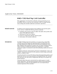
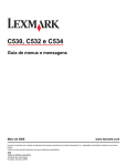
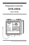
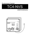
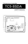
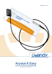
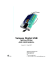
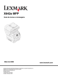
HELiOS RESERVOIR REFERENCE GUIDE PREFACE
This reference guide provides the information needed to unpack, set up, fill, and operate the Puritan Bennett HELiOS
Reservoir. This information is intended for use by technicians or personnel qualified to set up and fill medical liquid
oxygen equipment.
Statements in this reference guide preceded by the following words are of special significance:
WARNING
!
Means there is the possibility of injury or death to yourself or
others.
!
CAUTION: Means there is the possibility of damage to the unit or
other property, or situations causing reduced or no oxygen flow.
NOTE: Provides important information about using the equipment properly.
WARNING
!
FIRE, FROSTBITE, AND HIGH PRESSURE HAZARDS.
•Do not attempt to set up, fill, or operate the Reservoir until you
read and understand the information in this reference guide.
•Read the HELiOS Patient Operating Instructions (P/N B-701641-00)
before operating the Reservoir.
WARNING
!
IMPROPER USAGE HAZARD.
Oxygen supplied from this equipment is
for supplemental use and is not intended to be life supporting or
life sustaining. This equipment is not intended for use by patients
who would suffer immediate, permanent, or serious health consequences as a result of an interruption in their oxygen supply.
NOTE: The HELiOS Reservoir unit is intended only for the delivery of medical
grade oxygen as prescribed by a physician.
For product assistance contact:
Mallinckrodt, Inc.
5647 Dividend Drive
Indianapolis, IN 46241
Customer Service
1-800-635-5267
Technical Support
1-800-255-6774, press 2
Corporate Headquarters:
Mallinckrodt, Inc.
675 McDonnell Blvd.
P.O. Box 5840
St. Louis, MO 63134-5354
Telephone: 314-654-5345
Fax: 314-654-5345
Toll-Free: 1-800-635-5267
Information contained in this document, including performance specifications, is subject to change without notice.
Mallinckrodt makes no warranty of any kind with regard to the material in this document, including, but not limited to, the
implied warranties of salability and fitness for a particular purpose. Mallinckrodt shall not be liable for errors contained
herein or for incidental or consequential damages in connection with either providing this document or the use of material
in this document.
B-701742-00 Rev. A
HELiOS Reservoir Reference Guide Preface
HELiOS RESERVOIR REFERENCE GUIDE
1.0
PRODUCT DESCRIPTION
The HELiOS Reservoir (Figure 1) is part of an innovative liquid oxygen system that
provides 24 hour per day home oxygen therapy with typically less than one liquid oxygen
delivery per month. The Reservoir provides the patient with a source of liquid oxygen to
fill any HELiOS Portable for ambulatory use and a source of gaseous oxygen to power the
HELiOS 300 Portable at home. The unique design of the Reservoir virtually eliminates
oxygen evaporative losses both in standby mode and when supplying gaseous oxygen to
a patient. The Reservoir is available in two models that are nearly identical with the
exception of the liquid oxygen storage capacity. The H-46 holds 110 pounds of liquid
oxygen while the H-36 holds 85 pounds of liquid oxygen.
Figure 1: HELiOS H-46 and H-36 Reservoir Units
The Reservoir uses the popular Puritan Bennett top fill connector and is compatible with
Puritan Bennett Companion® filling equipment (vent wrench, transfer hose assembly,
source tank). The Reservoir requires a minimum 24 psig (166 kPa) saturated liquid oxygen
to operate and may be filled using standard or fast fill techniques (Section 6.0). A standard
integral pressure indicator on the unit helps the filling technician maintain proper liquid
oxygen saturation pressure during the fill. An electronic contents indicator uses reliable,
differential pressure based level sensing technology to provide accurate and easy to read
liquid oxygen contents indication. The 9-volt battery powered contents indicator incorporates high visibility LEDs for indicating liquid oxygen contents. LEDs also warn of low
battery and low contents conditions.
B-701742-00 Rev. A
HELiOS Reservoir Reference Guide - 1
The Reservoir provides 22 psig (152 kPa) gaseous oxygen at up to 10 L/min continuous
flow through a Diameter Index Safety System (DISS) connection. Oxygen outlet pressure
is regulated at 22 psig (152 kPa) since the unique design of the Reservoir allows internal
pressure to climb as high as 45 psig (311 kPa). A flexible oxygen supply tube, attached to
the outlet connector, provides gaseous oxygen to power the H-300 Portable.
To fill the Portable with liquid oxygen, the patient merely engages the quick connect
couplings on the Portable and Reservoir. The patient then opens the Portable vent valve
to begin filling and closes the vent valve a short time later to terminate the fill. Reservoir
pressure transfers slightly less than one pound of liquid oxygen into the H-300 Portable.
Depressing a release button disengages the Portable from the Reservoir. Due to different
operational specifications, Companion® System portables can not be filled from the
HELiOS Reservoir.
2.0
PERFORMANCE SPECIFICATIONS
The HELiOS Reservoir H-36 and H-46 performance specifications are listed below in
Table 1.
TABLE 1
HELiOS RESERVOIR SPECIFICATIONS
MODEL
H-36*
H-46*
Volume of Liquid
Oxygen at 22 psig (152
kPa) Saturation
(typical)
36 liters/1.27 ft3
46 liters/1.62 ft3
Weight of Liquid
Oxygen (typical)
85 lbs/38.6 kg
110 lbs/49.9 kg
Gaseous Oxygen
Equivalent at 1atm.
and 70°F
29,069 liters/1027 ft3
37,619 liters/1328 ft3
Height
33.5 in./85.1 cm
37.5 in./95.3 cm
Diameter
15.4 in./39.1 cm
15.4 in./39.1 cm
Empty Weight
50 lbs./22.7 kg
60 lbs/27.2 kg
Full Weight
135 lbs/61.2 kg
170 lbs/77.1 kg
* Specifications subject to change without notice.
2 - HELiOS Reservoir Reference Guide
B-701742-00 Rev. A
H ELiOS R ESER VOIR SPEC IFIC ATION S
MOD EL
H -36*
H -46*
Outlet Pressure
22 psi g/152 kPa Nomi nal
(Acceptable Range 20.5-23.0
psi g/141-159 kPa)
22 psi g/152 kPa Nomi nal
(Acceptable Range 20.5-23.0
psi g/141-159 kPa)
Economiz er Pressure
27 psi g/186 kPa Nomi nal
(Acceptable Range 24.0-30.0
psi g/166-207 kPa)
27 psi g/186 kPa Nomi nal
(Acceptable Range 24.0-30.0
psi g/166-207 kPa)
Primary R elief Valve
Pressure
45 psi g/311 kPa Nomi nal
(Acceptable Range
42-48 psi g/290-331 kPa)
45 psi g/311 kPa Nomi nal
(Acceptable Range
42-48 psi g/290-331 kPa)
Secondary R elief
Valve Pressure
70 psi g/483 kPa Nomi nal
(Acceptable Range
65-75 psi g/449-518 Pa)
70 psi g/483 kPa Nomi nal
(Acceptable Range
65-75 psi g/449-518 Pa)
N ormal Evaporation
R ate (typical)
(maximum)
1.2 lbs/0.54 kg per D ay
1.5 lbs/0.68 kg per D ay
1.2 lbs/0.54 kg per D ay
1.5 lbs/0.68 kg per D ay
Fill Time
(standard technique)
(fast fill technique)
Warm < 8 mi n./C old < 6 mi n.
Warm < 4 mi n./C old < 3 mi n.
Warm < 9 mi n./C old < 7 mi n.
Warm < 5 mi n./C old < 4 mi n.
Maximum Outlet Flow
10 L/mi n
10 L/mi n
C ontents Indicator
Electroni c, D i fferenti al
Pressure Based w/Remote
Indi cati on Opti on
Electroni c, D i fferenti al Pressure
Based w/Remote Indi cati on
Opti on
-20° C to 40° C
95% max. relati ve humi di ty
-40° C to 70° C
90% max. relati ve humi di ty
-20° C to 40° C
95% max. relati ve humi di ty
-40° C to 70° C
90% max. relati ve humi di ty
Environmental
(Operating Temp.)
(Storage Temp.)
* Specifications subject to change without notice.
B-701742-00 Rev. A
HELiOS Reservoir Reference Guide - 3
3.0
UNPACKING, INSTALLATION, AND REPACKING
Perform the following procedures when unpacking, installing or repacking a HELiOS
Reservoir unit.
3.1 Unpacking
1.
Examine the shipping carton for damage. If the carton is damaged, or its contents are
suspected of being damaged, photograph the damaged carton before the Reservoir is
unpacked. Contact the carrier to request a damage inspection. Contact the shipping
point immediately.
2.
Place the shipping carton on a flat surface with the shipping arrows pointing upwards.
3.
Open the top flaps of the shipping carton and remove accessory items.
4.
Remove the plastic bag covering the Reservoir and any loose packing inserts.
5.
With the assistance of a helper, grasp a handle on the side of the Reservoir. Hold the
carton down with one hand and carefully lift the Reservoir up and out of the carton.
6.
Compare the packing list attached to the carton’s exterior with the shipment received.
If any discrepancies exist, contact Mallinckrodt immediately at 1-800-497-4968.
7.
Thoroughly inspect the exterior of the Reservoir for damage (dents, cracks, etc.).
8.
Save all packing materials and the shipping carton for reuse.
3.2 Installation
Before installing the Reservoir in a patient’s home, read and understand Section 4,
Controls, Indicators, and Connectors; Section 5, Safety Precautions; Section 6, Filling
Instructions; and Section 7, Operating Procedures. Perform the following steps upon
receipt of shipment:
1.
Remove the moisture container and record the Reservoir serial number. Reinstall the
moisture container.
2.
Verify the fill connector release button and mechanism move freely.
3.
Press the button on the contents indicator. Verify that the yellow low contents LED
lights.
4.
Verify that a Reservoir vent wrench is available for filling the unit.
5.
Verify receipt of the HELiOS Patient Operating Instructions.
4 - HELiOS Reservoir Reference Guide
B-701742-00 Rev. A
3.3 Repacking for Return
To return a product, contact Mallinckrodt at 1-800-255-6774 (press 2) and ask to speak
with a Technical Support Representative. A Return Goods Authorization (RGA) number
will be issued to track the product return. Please have available your account number, the
model and serial number of the product, and the reason for returning the product when
you call to request an RGA. Return the unit in its original carton, if possible. If the original
carton is not available, you may purchase a new carton.
WARNING
!
4.0
Fire hazard and extreme cold hazard. Do not package or ship units
that contain liquid or gaseous oxygen. Liquid oxygen spillage and
high oxygen concentrations are possible. Empty oxygen contents
completely before packaging or shipping units.
1.
Obtain the proper carton and inserts for the Reservoir you wish to package.
2.
Make sure that the carton inserts are properly in place.
3.
With the assistance of a helper, grasp a handle on the side of the Reservoir and
carefully lift the Reservoir up and into the carton. Make sure the inserts snugly
support the Reservoir.
4.
Fold down the set of carton top flaps that press against the top of the Reservoir. Fold
down the second set of flaps and insert the locking tabs into the first set of flaps.
5.
Secure the carton with packing tape.
CONTROLS, INDICATORS, AND CONNECTORS
The controls, indicators, and connectors that are used on the Reservoir unit are shown in
Figure 2. Their functions are described below.
4.1
Fill Connector
The Reservoir uses the top fill Puritan Bennett fill connector to transfer liquid oxygen to
and from the unit. It is the male half of a cryogenic quick connect coupling system. A
spring loaded poppet automatically opens when the connector is engaged and automatically closes when the connector is disengaged.
4.2
Release Button
Pressing the release button on the Reservoir activates the fill connector release lever
mechanism. This disengages either a portable oxygen unit or a liquid oxygen transfer line
from the Reservoir.
B-701742-00 Rev. A
HELiOS Reservoir Reference Guide - 5
4.3
Vent Valve
The vent valve is a quarter-turn ball valve that is accessible with a separate vent wrench
through a hole in the Reservoir top cover. The filling technician opens the vent valve to
vent the inner container during the Reservoir unit filling process. The technician closes
the valve upon terminating the filling process.
4.4
Pressure Indicator
The pressure indicator displays the status of the pressure inside the Reservoir unit. A
filling technician monitors the pressure indicator to help maintain a minimum 24 psig
(166 kPa) liquid oxygen saturation pressure in the Reservoir during a fill. Under normal
operating conditions, the indicator pointer typically indicates a pressure between 27 psig
(186 kPa) and 45 psig (311 kPa). The pressure indicator does not indicate the regulated
pressure at the Reservoir oxygen outlet.
4.5
Contents Indicator
The contents indicator displays the amount of liquid oxygen in the Reservoir. Depressing
the button on the contents indicator turns on from one to eight green light emitting diodes
(LEDs) that represent the empty to full range of the Reservoir. A yellow “low contents”
LED comes on when about 8.5 lbs. (3.9 kg) of liquid oxygen remain. A 9-volt battery
powers the contents indicator. A low battery yellow LED comes on when battery voltage
drops below a predetermined level.
4.6
Oxygen Outlet
The Reservoir oxygen outlet provides a source of 22 psig (152 kPa) regulated oxygen at a
maximum flow of 10 L/min. A spring activated poppet in the Diameter Index Safety System
(DISS) oxygen connector stops oxygen flow when there is nothing attached to the
connector. When a HELiOS Portable oxygen supply tube or a flow control device calibrated at 22 psig (152 kPa) is attached to the outlet, the connector poppet opens to allow
oxygen to flow.
4.7
Moisture Container
The moisture container is part of the Reservoir shroud assembly that collects condensed
water run-off from the warming coils. The lower shroud channels the water run-off into the
moisture container. The moisture container slides easily out of the lower shroud assembly
to be emptied.
6 - HELiOS Reservoir Reference Guide
B-701742-00 Rev. A
Pressure
Indicator
Vent
Valve
Contents
Indicator
Fill
Connector
Oxygen
Outlet
Release
Button
Moisture
Container
FIGURE 2: Controls, Indicators, and Connectors
5.0
SAFETY PRECAUTIONS
This section covers precautions and safe practices as they apply to facilities and personnel involved in servicing medical oxygen equipment. These precautions are divided into
three main areas: cold safety, expansion safety, and fire safety. To ensure reliability and
safety, the service techniques, work area, and equipment used in the storage, service, and
handling of this system must be of the highest standard. Refer to the HELiOS Patient
Operating Instructions (B-701641-00) for additional safety precautions regarding the use
of this equipment.
5.1
Cold Safety
WARNING
!
Extreme cold hazard. Liquid oxygen (-297°F/-183°C) will freeze skin
on contact. Never touch liquid oxygen or frosted parts.
WARNING
!
B-701742-00 Rev. A
Extreme cold hazard. Liquid oxygen can spill if the Reservoir is
tipped over. Keep the Reservoir upright at all times.
HELiOS Reservoir Reference Guide - 7
WARNING
!
Extreme cold hazard. Forceful discharge of liquid oxygen possible
if fill connector freezes open upon disengagement. Always dry fill
connectors with clean, dry, lint free cloth before fill.
Recommended Protective Clothing:
• Heavily insulated gloves (for example, cryogenic or welding gloves). Never use gloves
that are contaminated with grease or oil when working with liquid oxygen.
• Protective face shield.
• Long sleeve shirt. Wear natural fibers such as cotton or wool. Avoid synthetic
materials such as polyester or rayon.
• Long pants. Never wear pants with cuffs. Liquid oxygen may become trapped and
cause serious burns to skin. Wear natural fibers such as cotton or wool. Avoid
synthetic materials such as polyester or rayon.
• Protective cryogenic or welding apron.
Important Facts:
• Direct exposure to liquid oxygen or exposure to its vented gas or components cooled
by liquid oxygen can result in frostbite. If frostbite occurs, seek medical attention
immediately.
5.2
Expansion Safety
W
!
WARNING
Explosive hazard. Extreme high pressure can rupture container or
plumbing components. Be sure specified pressure relief devices
are present and functioning properly.
Important Facts:
• Liquid oxygen at atmospheric pressure expands at a ratio of approximately 860:1 (at 0
psig) when vaporizing into a gas (Figure 3). This can occur very rapidly when
exposed to the heat in the atmosphere.
• Ensure that the specified pressure relief devices are present and functioning properly
in any device that will contain liquid oxygen. This includes transfer hose assemblies.
GAS
LOX
1
860
Figure 3: Liquid Oxygen Expansion Ratio
8 - HELiOS Reservoir Reference Guide
B-701742-00 Rev. A
5.3
Fire Safety
WARNING
!
Fire Hazard. Do not smoke. Death or injury may occur.
WARNING
!
Concentrated Oxygen. Increased risk of fire. Keep away from:
• Sources of ignition (cigarettes, open flames, electrical
equipment, etc.)
• Sources of heat (furnaces, stoves, dryers, water heaters, etc.)
• Flammable materials (asphalt, oil, grease, petroleum jelly,
hand creams, aerosols, wood, etc.)
• Store and service oxygen systems in well-ventilated areas.
• If a liquid oxygen spill occurs indoors, open doors and windows
to ventilate the area. Avoid sources of ignition and do not walk
on or roll equipment over the affected area.
• Any clothing or porous material that is splashed with liquid
oxygen or otherwise absorbs high concentrations of oxygen
should be removed and aired for at least one hour away from
any source of ignition.
Important Facts:
The possibility of fire exists when the combination of a fuel, source of ignition, and
oxygen is present (Figure 4). High concentrations of oxygen (air is approximately 21%
oxygen) greatly enhance the possibility of combustion.
• Keep liquid oxygen equipment at least five feet away from electrical equipment.
• Obtain all replacement parts for medical oxygen equipment from the manufacturer.
• Before servicing, clean all tools that come into contact with the oxygen system.
• Use only recommended oxygen compatible cleaning and leak detection products.
• Keep the Reservoir upright at all times. Secure liquid oxygen equipment when
transporting to prevent accidental tipover and spillage.
Figure 4: Combustion Triangle
B-701742-00 Rev. A
HELiOS Reservoir Reference Guide - 9
6.0
FILLING INSTRUCTIONS
The Reservoir must be filled with liquid oxygen saturated at a minimum 24 psig (166 kPa) to
ensure proper operation. The information in this section will help you fill the Reservoir
with liquid oxygen in a proper, safe, and efficient manner.
6.1
Oxygen Source Requirements
The HELiOS Reservoir must be filled with only U.S.P. Medical Oxygen. The liquid oxygen
used for filling the Reservoir must have no moisture content. Liquid oxygen in the Reservoir must be saturated at a minimum 24 psig (166 kPa) for proper operation to occur. In
order to achieve at least 24 psig (166 kPa) saturation in the Reservoir, the saturation
pressure of the liquid oxygen filling source must be carefully considered. The filling source
saturation pressure requirement mainly depends on the type of filling technique used. The
Standard Fill technique requires a liquid oxygen source saturation pressure of 40-50 psig
(276-345 kPa). The Fast Fill filling technique requires a liquid oxygen source saturation
pressure of 24-28 psig (166-193 kPa). Following is a brief description of each filling
technique and corresponding liquid oxygen source requirement.
Both Reservoir filling techniques use pressure in the source tank as the force to drive the
liquid oxygen into the Reservoir. In order to transfer liquid oxygen from the source tank to
the Reservoir, a pressure differential must exist so that the source tank pressure remains
greater than the Reservoir pressure during the fill. The Standard Fill technique requires
the source saturation pressure to be greater than the saturation pressure needed in the
Reservoir. With the filling source saturated at 40-50 psig (276-345 kPa), the boiling action of
the liquid oxygen maintains the pressure differential as the Reservoir pressure is lowered
by opening its vent valve. Monitoring the Reservoir pressure indicator while adjusting
(throttling) the Reservoir vent valve enables the filling technician to maintain 24-28 psig
(166-193 kPa) saturation pressure in the Reservoir during the fill. However, liquid oxygen
saturated at 40-50 psig (276-345 kPa) is at a higher temperature than liquid oxygen saturated at 24-28 psig (166-193 kPa). During the fill, liquid oxygen saturated at 40-50 psig (276345 kPa) in the source tank boils rapidly to release heat and cool down to the lower
temperature required for 24-28 psig (166-193 kPa) saturation in the Reservoir. The rapid
boiling (desaturation) of the liquid oxygen creates a large volume of gaseous oxygen that
is vented out the Reservoir vent valve during the fill. With the source saturated at 50 psig
(345 kPa), about 8% of the liquid oxygen withdrawn from the source tank to fill the
Reservoir boils off into gas and is expelled through the vent valve as a result of the
depressurization (Figure 5). Consequently, slower fill times and greater filling losses occur
with the Standard Fill technique.
10 - HELiOS Reservoir Reference Guide
B-701742-00 Rev. A
Figure 5: Vapor Release from Depressurized Liquid Oxygen
The Fast Fill technique requires the liquid oxygen saturation pressure in the source tank
to be about 24-28 psig (166-193 kPa), the same as the saturation pressure needed in the
Reservoir. With the source saturated at 24-28 psig (166-193 kPa), rapid boiling
(desaturation) of the liquid oxygen does not occur as it moves from the source tank into
the Reservoir during a fill. However, in order to drive the liquid oxygen from the source
tank to the Reservoir, a pressure differential must exist so that the source tank pressure
remains greater than the Reservoir pressure during the fill. Consequently, a source tank
equipped with a pressure building circuit must be used with the Fast Fill technique. By
turning on the pressure building system in the source tank, a small amount of the liquid
oxygen in the tank vaporizes in a heat exchanger and builds pressure above the surface of
the liquid oxygen. This provides the head pressure (40-50 psig/276-345 kPa) needed to
drive the liquid oxygen saturated at 24-28 psig (16-193 kPa) into the Reservoir. The filling
technician maintains a minimum 24 psig (166 kPa) saturation in the Reservoir by monitoring the Reservoir pressure indicator and adjusting (throttling) the vent valve. Faster fill
times and less filling losses are the end results. The Fast Fill technique requires a source
tank that meets the following conditions:
1.
The source tank must be filled with liquid oxygen saturated at 24-28 psig
(166-193 kPa).
2.
The source tank must be equipped with a 24-28 psig (166-193 kPa) road relief valve, a
40-50 psig (276-345 kPa) pressure building relief valve, and a means to switch between
the two relief valves. The 24-28 psig (166-193 kPa) relief valve maintains source tank
saturation pressure between fills. The 40-50 psig (276-345 kPa) relief valve enables
pressure building to occur during a fill.
3.
The source tank must have a pressure building system capable of maintaining 40-50
psig (276-345 kPa) head pressure during each fill.
Since a variety of source tank configurations are available, contact Mallinckrodt Technical
Support for advice when considering a liquid oxygen source and filling technique to best
meet your needs.
B-701742-00 Rev. A
HELiOS Reservoir Reference Guide - 11
6.2
Transfer Line
The standard Puritan Bennett transfer line assembly (Figure 6) is used to transfer liquid
oxygen from the source tank to the Reservoir. The 5/8-in. flared connection on the transfer
line source adaptor connects to a mating fitting in the source tank liquid withdrawal valve.
WARNING
!
Explosive hazard. Extreme high pressure can rupture a transfer
line. Make sure a proper pressure relief valve is present and functional on the transfer line assembly.
Source
Adapter
150 PSI (1035 kPa)
Relief Valve
Puritan-Bennett
Fill Adapter
Transfer Hose
Figure 6: Standard Transfer Line Assembly
6.3 Pre-Fill Inspection
Perform the following procedure to visually inspect the Reservoir and determine its
operational status before filling. Correct observed problems before proceeding to fill the
Reservoir.
1.
2.
3.
4.
5.
Ask the patient if there are any questions or concerns regarding the equipment since
your last visit.
Visually inspect the Reservoir unit for overall product integrity (for example, cracked
or damaged components).
Verify that all labels are present and legible on the unit (Figure 7).
Verify that no frost or heavy condensation is present on the container below the
shroud and that there is no excessive venting from the relief valve. (Some venting
from the relief valve is normal.)
Verify that the liquid oxygen contents level is consistent with the delivery schedule
and expected patient usage.
12 - HELiOS Reservoir Reference Guide
B-701742-00 Rev. A
6.
7.
8.
Verify that the fill connector is not worn, leaking, or damaged.
Verify that the vent valve stops are not bent or broken.
Verify that the contents indicator is operational and at least one green LED lights
when the button is depressed. The yellow low contents LED may light if the Reservoir is low or empty. Replace the 9-volt battery if the yellow low battery LED is on.
9. Verify that the pressure displayed on the Reservoir pressure indicator is 24-48 psig
(166-331 kPa) if the unit contains liquid oxygen.
10. Verify that the moisture container is in place and empty.
HELiOS ®
OXYGEN
REFRIGERATED
LIQUID-USP
UN1073
Oxygen Connector
OXYGEN
2
701529
BY AIR LIQUEFACTION
WARNING
REV. A
Do not exceed 10 L/min
maximum flow.
701533 Rev. A
CAUTION
Wipe connector
dry before filling
HELiOS Reservoir
701528 Rev. A
DO NOT SMOKE near this unit. Keep
away from heat, flame or sparks.
Keep unit well ventilated at all times.
Do not touch frosted parts.
Keep unit in upright position.
Read Patient Operating Instructions.
Puritan-Bennett Corporation
Indianapolis, IN 46241 USA
CAUTION: Federal (USA) law
restricts this device to sale by
or on the order of a physician.
701527 Rev. A
Figure 7: Reservoir Labels
6.4
Filling Procedure
Perform the following procedure to fill a HELiOS Reservoir with liquid oxygen.
WARNING
!
Fire hazard. Liquid oxygen spilled on asphalt or any other combustible surface will increase the possibility of fire if an ignition source
is present. Always fill the unit on a non-combustible surface, such
as concrete or a steel drip pan.
WARNING
!
B-701742-00 Rev. A
Explosive hazard. Extreme high pressure can rupture a transfer
line. Make sure a proper pressure relief valve is present and functional on the transfer line assembly.
HELiOS Reservoir Reference Guide - 13
WARNING
!
Fire hazard. Liquid oxygen spillage will occur if the Reservoir is
tipped over. Before transporting, secure in an upright position
Reservoir units that contain liquid oxygen .
WARNING
!
Fire hazard. Oxygen can accumulate in a delivery vehicle. Exhaust
vent gases to outside of vehicle. (See CGA Safety Bulletin SB-9.)
1.
Wear the proper protective clothing (Safety Precautions, Section 5).
2.
Verify that the liquid oxygen saturation pressure in the source tank is 40-50 psig (276345 kPa) if using the Standard Fill technique. Verify that the liquid oxygen saturation
pressure in the source tank is 24-28 psig (166-193 kPa) if using the Fast Fill technique. Refer to Section 6.1, Oxygen Source Requirements for more information on
source tank requirements.
NOTE: If you experience difficulty obtaining properly saturated oxygen,
consult the Technical Service Department in Indianapolis for alternatives.
3.
Attach the 5/8-in. female end of the transfer line source adapter to the liquid withdrawal valve of the source tank. Position the source adapter relief valve straight up.
4.
If the Reservoir contains some liquid oxygen, verify that the Reservoir pressure
gauge reads 24-48 psig (166-331 kPa). A pressure reading outside of this range may
indicate a problem. If the unit is empty, continue with step 5 without verifying the
pressure at this point.
5.
Remove the fill connector cover from the fill connector, if present. (Available as
an option).
6.
Check the fill connectors on both the Reservoir unit and the fill adapter to ensure that
they are clean and dry. Wipe the connectors with a clean, lint-free cloth or blow-dry
with gaseous oxygen or nitrogen as needed.
7.
Use the vent wrench to open the vent valve on the Reservoir unit by rotating the
wrench a quarter-turn counterclockwise.
NOTE: At this point you may hear a venting noise if the Reservoir unit is
pressurized.
8.
Engage the transfer line to the fill connector on the Reservoir unit by aligning the fill
connector on the transfer line directly over the fill connector on the Reservoir. Apply
about 20 lbs. of downward force.
9.
Maintain a downward force on the transfer line fill adapter while slowly opening the
liquid valve on the source tank. At this point a vigorous audible venting noise will
confirm that the filling process has started. Adjust the source tank liquid valve as
needed to keep the pointer on the Reservoir pressure indicator at 24-28 psig
(166-193 kPa).
14 - HELiOS Reservoir Reference Guide
B-701742-00 Rev. A
NOTE: It may be necessary to open the source tank liquid valve completely and partially
close the Reservoir vent valve to maintain the proper pressure throughout the fill.
10. Close and reopen the vent valve on the Reservoir after 45 to 60 seconds have passed.
This will minimize the possibility of the vent valve freezing in the open position.
NOTE: As the level of liquid oxygen nears the top of the Reservoir inner container,
the sound and appearance of vapors escaping through the vent valve will change.
The vapor will become denser, and as liquid oxygen reaches the vent valve, a
discharge of liquid oxygen will be visible and audible.
NOTE: The first observed discharge of liquid oxygen usually results from turbulence
inside the container and does not necessarily indicate the unit is full. To ensure a
complete fill, continue filling until you observe a steady stream of liquid oxygen.
WARNING
!
Extreme cold hazard. Liquid oxygen discharge from the fill
connector can occur. When disconnecting the transfer line, never
stand directly over the Reservoir fill connector. If the Reservoir fill
connector stays open and minor liquid oxygen discharge occurs,
carefully re-engage and disengage the transfer line to help
dislodge any ice or other obstruction. If major liquid oxygen discharge (steady stream) occurs, open the vent valve (if safely possible) to vent pressure and stop the release of liquid oxygen. Open
windows to ventilate the room and do not walk on areas exposed to
liquid oxygen for 60 minutes after frost disappears.
11. When you notice a steady stream of liquid oxygen exiting the vent valve, disconnect
the transfer line from the Reservoir by depressing the portable release button and
lifting the fill adapter straight up. Close the vent valve immediately by rotating the
vent wrench a quarter-turn clockwise.
!
CAUTION: If the vent valve freezes in the open position, terminate
the fill by disconnecting the transfer line and then allow the vent
valve to warm until it closes easily. If the vent valve remains open
for a period of time, the liquid oxygen in the unit will desaturate to
a pressure lower than required. If this occurs, refer to Section 6.6,
Checking Saturation Pressure.
12. Replace the fill connector cover, if present, on the Reservoir unit. Close the source
tank liquid valve when the frost melts from the transfer line assembly.
WARNING
!
B-701742-00 Rev. A
Extreme cold hazard. Liquid oxygen discharge from the transfer
line relief valve can occur. Closing the source tank liquid valve
before the frost on the transfer line melts may trap liquid oxygen in
the transfer line. This may cause the relief valve to open forcefully.
Never place hands, arms, or face directly over the relief valve.
HELiOS Reservoir Reference Guide - 15
6.5 Post-Fill Inspection
Perform the following procedure to inspect the Reservoir and determine its operational
status after filling it with liquid oxygen. Correct observed problems before placing the unit
in service.
1.
Verify that the Reservoir fill connector poppet is closed and not leaking.
2.
Verify that the vent valve is completely closed and not leaking.
3.
Verify that the Reservoir pressure indicator reads at least 24 psig (166 kPa) within five
minutes after terminating the fill.
4.
Verify that there is no frost or heavy condensation on the container below the
shroud.
5.
Verify that all green LEDs light when the contents indicator button is depressed.
6.6 Checking Saturation Pressure
Perform the procedure listed below as needed to determine the saturation pressure of the
liquid oxygen in a Reservoir unit. The Reservoir pressure indicator reading may not
always be a true indication of the liquid oxygen saturation pressure.
1.
Note the pressure indicated by the Reservoir pressure indicator.
2.
Momentarily open the vent valve on the Reservoir and observe the pressure indicator
pointer as it drops.
3.
Note the pressure value where the indicator pointer hovers (Figure 8) and then close
the vent valve. This is the approximate saturation pressure of the Reservoir. Saturation pressure readings between 24 and 48 psig (166 and 331 kPa) are in the acceptable
pressure range of the unit.
Initial Pressure
Indication
False Head
Pressure
True Saturation
Pressure
Figure 8: Indicator Needle “Hovering”
16 - HELiOS Reservoir Reference Guide
B-701742-00 Rev. A
6.7 Resaturating Liquid Oxygen
If the HELiOS Reservoir looses its saturation pressure and you correct the cause of this
condition without emptying the liquid oxygen contents, saturation pressure can be
restored by simply allowing the unit to stand in normal room conditions for a specified
amount of time. The entire volume of liquid will usually regain proper saturation within
several days. If, however, this is not a reasonable option, perform the following procedure:
1.
Attach the source adapter of the transfer line assembly to either the gas withdrawal
circuit or vent circuit of the source tank.
2.
Connect the transfer line fill adapter to the Reservoir unit fill connector and depress
to engage the fill connectors.
3.
Slowly open the vent valve or gas withdraw valve on the source tank and monitor the
Reservoir pressure gauge. Open the source tank valve just enough to see a slow,
steady rise in the pressure gauge pointer. Be sure to leave the Reservoir vent valve
closed.
4.
When the Reservoir pressure indicator pointer reaches 24-28 psig (166-193 kPa), close
the source tank valve.
5.
Recheck the saturation pressure as described in Section 6.6. Repeat the resaturation
procedure, if necessary, until the liquid oxygen is saturated.
NOTE: Be sure to reconnect the transfer line to the source tank liquid valve after
completing this procedure.
7.0
OPERATING PROCEDURES
The patient uses the HELiOS Reservoir in two different ways. First, the Reservoir provides
the patient with a liquid oxygen filling source for the HELiOS Portable. Second, it provides
gaseous oxygen for the patient to breathe through the H-300 Portable when at home.
Procedures for filling the Portable from the Reservoir are found in the HELiOS Patient
Operating Instructions. To operate the Reservoir as a source of gaseous oxygen to supply
the H-300 Portable, perform the following steps:
B-701742-00 Rev. A
1.
Verify that there is adequate liquid oxygen in the Reservoir to meet patient breathing
needs.
2.
Verify that the Reservoir pressure indicator reads 24-48 psig (166-331 kPa). The
pressure at the Reservoir outlet is regulated at 22 psig (152 kPa).
3.
Connect one end of the flexible oxygen supply tube to the Portable oxygen supply
tube quick connect. Use the tube end that has the male half of the quick connect
attached (Figure 9).
4.
Attach the opposite end of the flexible oxygen supply tube to the oxygen outlet
fitting on the side of the Reservoir. Screw the nut and barbed fitting onto the oxygen
outlet fitting until snug.
HELiOS Reservoir Reference Guide - 17
5.
Verify that the tube connections are leak tight.
6.
Place one of the tubes from the dual-lumen oxygen cannula on the H-300 Portable
oxygen outlet connector (upper connector). Place the other cannula tube on the
sensor connector (lower connector). Adjust the cannula on the face to receive
oxygen comfortably.
7.
Set the H-300 Portable flow control knob to the prescribed oxygen flow setting.
NOTE: For additional information, refer to the HELiOS Patient Operating Instructions.
(a)
(b)
Figure 9: Flexible Oxygen Supply Tube Connections
18 - HELiOS Reservoir Reference Guide
B-701742-00 Rev. A
TECHNICAL BULLETIN
HELiOS OXYGEN SYSTEM
TECHNICAL SUPPORT INFORMATION
Mallinckrodt wishes to ensure current and future customer satisfaction regarding the release of the new
HELiOS Oxygen System. To meet this objective, it is important that we have an opportunity to carefully
investigate any HELiOS performance and service issues that may arise.
From January 2000 through June 2000 we request that any HELiOS Reservoir or Portable with a service
related issue be returned to the Mallinckrodt Indianapolis Technical Service Center for evaluation and
disposition. A technical service manual, service parts, and service training will be available to our customers
following this evaluation period.
Please contact the Technical Service Center in Indianapolis, IN at 1-800-255-6774 Press 2 if you have
questions regarding HELiOS service and to determine if the product must be returned for evaluation.
The attached HELiOS Reservoir Reference Guide will assist you with the set up, filling, and operation of
the HELiOS Reservoir. Similar information regarding the HELiOS H-300 Portable is available in the
HELiOS Patient Operating Instructions (P/N B-701641-00) that is supplied with each unit.
01/19/00
B-701742-00 Rev. A