1
SMA7215 MANUAL
Chapter Six: Start Up and Calibration
6.1 Introduction:
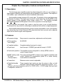
This chapter contains the procedure required for initial start up and amplifier calibration.
The SMA7215 amplifier can be configured to run in velocity mode(6.3) and current
mode(6.4).
NOTE: The SMA7215 amplifier can also be pre-configured to run in the BEMF mode. Please
consult a Glentek applications engineer for detailed information on BEMF mode.
Required Equipment: Oscilloscope, voltmeter & battery box. The battery box serves as a
step input voltage command, applying and removing a flashlight battery can also be used for
this function. Glentek sells a battery box BB-700 which is ideal for this function.
6.2 Initial Start Up:
When applying power to start up your amplifier system for the first time, we recommend
you follow this procedure. If you have already gone through this procedure you can skip to
the appropriate calibration procedure.
1. Check for any loose or damaged components.
2. Check that all connections are tight.
3. Be sure that the motor mechanism is clear of obstructions. If the mechanism has limited
motion, e.g: a lead-screw, set the mechanism to mid-position.
4. Disconnect the signal inputs.
5. Be sure the Loop-Gain pot (RV1) is fully CCW.
6.3 Calibration of the Velocity Mode Amplifier:
The amplifier, in this configuration, receives an analog, bi-polar input command which is
proportional to the required motor velocity. The amplifier receives velocity feedback from a
tachometer which is usually mounted to the rear of the motor. The following pots will be set
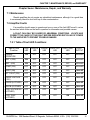
during calibration: (Note: RV1-RV5 are single turn pots and RV6-RV13 are 12-turn pots.)
Note: RV2, RV3, RV4 and RV5 are factory set and should not be adjusted. Adjusting these
pots voids warranty.
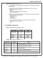
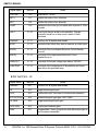
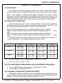
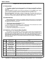
Pots
Name of Pot
RV1
RV8
Loop Gain,
LOOP GAIN
Differential Gain,
DIFF SIG GAIN
Signal Gain,
SIG GAIN
Balance, BAL
RV9
Tach. Gain, TACH
RV6
RV7
Notes
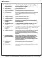
Used to shut off uncalibrated amplifiers. When the loop gain is
fully CCW, no current is delivered to the motor.
Sets the input voltage to velocity ratio for differential signal input.
Sets the input voltage to velocity ratio for single-ended signal input.
Used to null any offsets in system.
Sets the DC tachometer gain.
RV10 Compensation, COMP Used in conjunction with tach. gain to set the system bandwidth.
RV13
21
Current Limit, I LIMIT
Sets the maximum motor current. Shipped set CCW (min. current).
GLENTEK Inc. 208 Standard Street, El Segundo, California 90245, U.S.A. (310) 322-3026