1
SMA7215 MANUAL
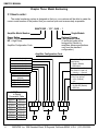
Chapter Three: Model Numbering
Page
3.1 How to order ................................................................................................ 15
Chapter Four: Installation
4.1 Introduction .................................................................................................. 16
4.2 Mounting ...................................................................................................... 16
4.3 Wiring........................................................................................................... 16-19
4.3.1 RFI/EMI and Wiring Technique .......................................................... 16
4.3.2 Wire Size and Type ............................................................................ 17
4.3.3 Connector Size and Type ................................................................... 17-18
4.3.3.1 The Power Connector............................................................... 18
4.3.3.2 The Signal Connector ............................................................... 19
4.3.4 Amplifier Connections ........................................................................ 18-19
4.3.4.1 The Power Connections ........................................................... 18
4.3.4.2 The Signal Connections............................................................ 18-19
4.3.5 Test Point ........................................................................................... 19
Chapter Five: Configuration
5.1 Introduction .................................................................................................. 20
5.2 Logic Input Configuration ............................................................................. 2 0
5.2.1 +15V/+5 Logic Level Configuration .................................................... 20
5.2.2 Velocity/Voltage Feedback Mode and Current Mode Configuration....20
5.2.3 Integrator Configuration...................................................................... 20
Chapter Six: Start Up and Calibration
6.1 Introduction .................................................................................................. 21
6.2 Initial Start Up .............................................................................................. 21
6.3 Calibration of the Velocity Mode Amplifier ................................................... 21-23
6.4 Calibration of the Current Mode Amplifier.................................................... 23-24
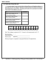
6.5 Calibration Setup Record............................................................................. 25
3
GLENTEK Inc. 208 Standard Street, El Segundo, California 90245, U.S.A. (310) 322-3026