1
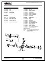
BALANCED DIAPHRAGM FIRST STAGE
R
O
DISASSEMBLY PROCEDURE
NOTE: Be sure to check and record the Intermediate Pressure and perform the Leak Detection Test outlined in the
Initial Inspection Procedures (Doc. 12-7508) prior to Disassembling the Regulator. Review the Troubleshooting Section on page 3 to gain a better idea of which internal parts may
be worn, and to better advise your customer of the service
that is needed.
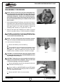
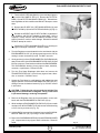
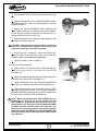
1. Before disassembling the First Stage, remove the Low Pressure
Hoses with a 9/16" open end wrench, the High Pressure Hose(s)
with a 5/8" open end wrench, and the Low Pressure Inflator Hose
with either a 9/16" or 1/2" open end wrench. Remove all
remaining PORT PLUGS (21, 23) with a 5/32" hex key.
Fig. 1
2. Remove and inspect the O-RING(S) now visible on all these
items for any signs of decay. If found, discard the O-RING(S).
CAUTION: It is important to remove the YOKE/DIN Connector end components first to avoid damage of the HP Seat
Cone located inside the BODY (30).
NOTE: For units received with Yoke Connectors perform
step 3Y. For those with DIN Connectors perform step 3D.
3Y. Yoke Connector Disassembly:
A. Remove the KNOB (1) from the YOKE (2)
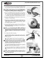
B. Secure the BODY (30) in a soft jawed or well padded vise and
apply a thin wall, or modified, 1" open end wrench to the YOKE
RETAINER (6). Using firm steady force, turn the YOKE RETAINER counter clockwise to loosen it. DO NOT use impact.
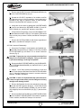
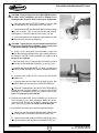
Fig. 2
CAUTION: It is important that the wrench is properly seated
over the entire hex portion of the YOKE RETAINER to prevent
any damage to the part (Fig. 1).
CAUTION: Tighten the vise only as needed to hold the First
Stage secure, and DO NOT overtighten. Doing so will result
in permanent damage, rendering it inoperable.
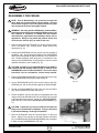
C. Remove the Regulator from the vise and stand it on the work
bench with the Yoke end up (Fig. 2).
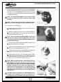
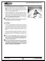
D. Lift the YOKE (2), YOKE RETAINER (6) with RETAINING
SPRING (18), and HP SEAT (20) straight up and out of the BODY
(30) (Fig. 3) and set them aside.
E. Remove the DUST CAP (17), and set it aside.
Fig. 3
© 2002 Design 2003
4
Product Service Manual
Doc. No. 12-7509-r01 (3/24/03)