1
BALANCED DIAPHRAGM FIRST STAGE
R
O
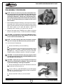
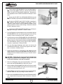
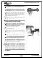
C. Insert the SWIVEL POST (25) into the SWIVEL (29).
D. While holding the BODY (30) secure, install the SWIVEL
Assembly into the LP Port located below the flat portion of the
BODY (Fig. 26), and tighten it clockwise with a 5/32" hex key
socket to a torque of 40 to 50 in-lbs.
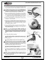
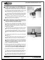
12. Lubricate and install all Hose O-rings onto Hoses and install the
Hoses into the BODY (30). While holding the BODY secure,
tighten the LP Second Stage Hose(s) clockwise with a 9/16"
open end wrench, the HP Hose(s) with a 5/8" open end wrench,
and the LP Inflator Hose(s) with either a 9/16" or 1/2" open end
wrench, all to a torque of 35 to 40 in-lbs.
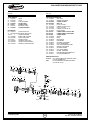
Fig. 26
CAUTION: Be certain NOT to install any Low Pressure Hose
into a High Pressure Port using an adaptor.
ADJUSTMENT
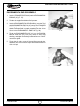
1. Connect a recently calibrated Intermediate Pressure Test Gauge
to a Low Pressure Hose, and connect the First Stage with
Second Stage and Low Pressure Test Gauge to a pure breathing
gas source of 3000 PSI. Slowly open the supply valve to
pressurize the Regulator, and purge the Second Stage several
times.
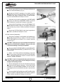
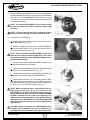
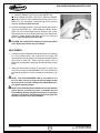
2. Adjust the Intermediate Pressure, if necessary, to read 138 to
142 PSI by turning the ADJUSTMENT CUP (38) clockwise to
increase the pressure or counter clockwise to decrease it (Fig.
24).
NOTE: Turn the ADJUSTMENT CUP no more than 1/8 of a
turn at a time, pausing to purge the Second Stage several
times to gain an accurate reading of the Intermediate Pressure before adjusting further.
NOTE: Ensure that the Intermediate Pressure holds stable at
138 to 142 PSI, and does not creep or fluctuate after the
Second Stage has been purged several times. If creeping is
detected, refer to the Troubleshooting Section on page 3 to
determine possible cause and treatment.
© 2002 Design 2003
12
Product Service Manual
Doc. No. 12-7509-r01 (3/24/03)