1
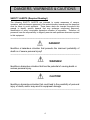
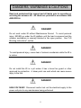
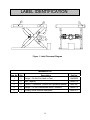
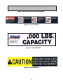
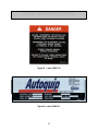
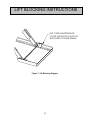
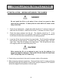
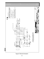
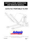
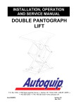
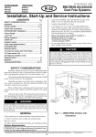
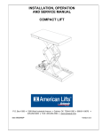
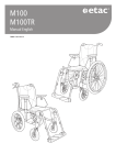
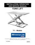
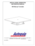
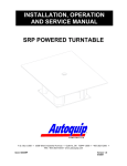
INSTALLATION, OPERATION
AND SERVICE MANUAL
MECHANICAL
SCISSORS LIFT
P.O. Box 1058 • 1058 West Industrial Avenue • Guthrie, OK 73044-1058 • 405-282-5200 •
FAX: 405-282-8105 • www.autoquip.com
Item # 830LA
Version 1.0
09/2001
TABLE OF CONTENTS
Identification and Inspection
3
Dangers and Warnings
4
Label Identification
8
Specifications
11
Lift Blocking Instructions
12
Installation Instructions
14
Operating Instructions
17
Routine Maintenance
18
General Maintenance
19
Replacement Parts List
21
Troubleshooting Analysis
22
IMPORTANT
Please read and understand this manual prior to installation or operation of this lift.
Failure to do so could lead to property damage and/or serious personal injury. If any
questions arise, call a local representative or Autoquip Corporation at 1-888-811-9876
or 405-282-5200.
PLANNED MAINTENANCE PROGRAM
A local Autoquip representative provides a Planned Maintenance Program (PMP) for
this equipment using factory-trained personnel. Call a local representative or Autoquip
Corporation at 1-888-811-9876 or 405-282-5200 for more information.
2
IDENTIFICATION & INSPECTION
IDENTIFICATION
When ordering parts or requesting information or service on this equipment, PLEASE
REFER TO THE MODEL AND SERIAL NUMBER. This information is on a nameplate
attached to the leg assembly. Replacement parts are available from a local Autoquip
distributor.
INSPECTION
Immediately upon receipt of the unit, a visual inspection should be made to determine
that it has not been damaged in transit. Any damage found must be noted on the
delivery receipt. In addition to this preliminary inspection, the unit should be carefully
inspected for concealed damage. Any concealed damage found that was not noted on
the delivery receipt should be reported in writing to the delivering carrier within 48 hours.
The following is a checklist that will aid in the inspection of this equipment.
1. Examine the entire unit for any signs of mishandling.
2. Pay special attention to gearboxes, mechanical actuators & wiring.
3. After installation, raise and block the lift and inspect the base frame, scissors
assembly and mechanical drive system. See the “Lift Blocking Instructions” section.
3
DANGERS, WARNINGS & CAUTIONS
SAFETY ALERTS (Required Reading!)
The following SAFETY ALERTS are intended to create awareness of owners,
operators, and maintenance personnel of the potential safety hazards and the steps that
must be taken to avoid accidents. These same alerts are inserted throughout this
manual to identify specific hazards that may endanger uninformed personnel.
Identification of every conceivable hazardous situation is impossible. Therefore, all
personnel have the responsibility to diligently exercise safe practices whenever exposed
to this equipment.
____________________________________________________________
DANGER!
Identifies a hazardous situation that presents the imminent probability of
death or of severe personal injury!!
_____________________________________________________________
WARNING!
Identifies a hazardous situation that has the potential of causing death or
serious personal injury.
CAUTION!
Identifies a hazardous situation that could lead to the possibility of personal
injury of death, and/or may result in equipment damage.
_____________________________________________________________
4
DANGERS, WARNINGS & CAUTIONS
Read and understand this manual and all labels prior to operating or
servicing the scissors lift. All labels are provided in accordance with
ANSI Z535.4.
DANGER!
Do not work under lift without Maintenance Device! To avoid personal
injury, NEVER go under the lift platform until the load is removed and the
scissors mechanism is securely blocked in the open position. See "Lift
Blocking Instructions" section.
DANGER!
To avoid personal injury, stand clear of scissors mechanism while the lift is
in motion.
DANGER!
Do not install the lift in a pit unless it has a bevel toe guard or other
approved toe protection. A shear point can exist which can cause severe
injury to the foot.
DANGER!
HIGH VOLTAGE!! Disconnect and/or lock out the electrical supply to the
power unit prior to any maintenance being performed.
5
DANGERS, WARNINGS & CAUTIONS
DANGER!
Scissors lifts are designed individually for a specific load and application.
To avoid personal injury, do not change the load or application from the
original design.
WARNING!
NEVER stand, sit or ride on the lift!
WARNING!
All warning and information decals should be in place as outlined in the
“Label Identification” section. If decals are missing or damaged, they
should be replaced with new ones. Contact Autoquip for replacements.
WARNING!
Do not attempt to remove the drive mechanism until the maintenance locks
securely support the empty lift. Failure to do so could results in personal
injury or death!
WARNING!
Lift platforms traveling below floor levels may create openings, and the
shape of the load and how the load is arranged on the lift may create a toe
hazard as the load passes the top edge of the pit. Both situations may
require guarding in accordance with Federal Regulations. Any such
guarding must be installed prior to operating the lift.
.
6
DANGERS, WARNINGS & CAUTIONS
CAUTION!
When moving the lift, do not attempt to pick it up by the platform; it is
hinged and could be damaged. Pick up from under the base frame ONLY.
CAUTION!
Do not continue to activate the “UP” button if the lift is not raising or if it has
reached the fully raised position. To do so may result in permanent
damage to the lift.
CAUTION!
Precautions should be taken to prevent the introduction of contaminates
such as dirt or other foreign material into the drive system through open
fittings, pipes or disassembled components. Contamination will ruin the
drive mechanism.
7
LABEL IDENTIFICATION
2
3
1
4
5
Figure 1 Label Placement Diagram
Mechanical Lift
Item No.
Qty
Description
1
2
Danger – Do Not Put Hands or Feet . . .
36430050
2
2
Max. Capacity
36405710
3
2
Caution – Familiarize Yourself with Operators Manual
36401487
4
2
Danger – Do Not Disassemble Motor / Gearbox
36405110
5
1
Autoquip Serial Number Nameplate
36401511
8
Part No.
LABEL IDENTIFICATION
Note: Labels shown here are not actual size.
Figure 2 Label 36430050
Figure 3 Label 36401586
Figure 4 Label 36401487
9
LABEL IDENTIFICATION
Figure 5 Label 36405110
Figure 6 Label 36401511
10
SPECIFICATIONS
LOAD CAPACITY
The load capacity rating is stamped on a metal plate attached to one side of the lift.
This figure is a net capacity rating for a lift furnished with the standard platform. Where
gravity roll-sections, special tops, etc, are installed on the lift after leaving the plant,
deduct the weight of these from the load rating to obtain the net capacity. Lifts should
not be overloaded beyond the established capacity as damage and/or personal
injury may result.
UNBALANCED LOADING
The stabilization provided is basically for balanced loads. If special attachments extend
beyond the length and/or width dimensions of the platform, the end and/or side load
capacity is reduced 2% for each one-inch extension from the center. If the load is
rolling onto the platform (in any but the fully-lowered position) the end and/or side load
capacity is reduced by a 50% impact factor (i.e., divide the rated end/side load by 1.50
to establish an available “axle” load).
11
LIFT BLOCKING INSTRUCTIONS
1. Remove all load from the platform. Never block the lift when loaded.
2. Raise the platform sufficiently for the base rollers to rollback past the flip-over
maintenance locks, located on the base frame of the lift.
3. Engage both maintenance locks by flipping them over (see Figure 7).
4. Lower the platform until the base rollers just come into contact with and rest against
the maintenance locks.
5. Always shut off the main electrical switch, when blocked, to prevent someone from
turning it on.
DANGER!
To avoid personal injury, NEVER go under the platform until the load is
removed and the lift is securely blocked in the open position.
6. To remove the maintenance locks, raise the platform by activating the “UP” switch to
provide sufficient clearance for the removal of the maintenance locks.
DANGER!
Maintenance locks that are bent, damaged, or non-functional must be
replaced immediately to avoid personal injury. Contact the Autoquip
Service Department for replacement parts and installation instructions.
12
LIFT BLOCKING INSTRUCTIONS
FLIP-OVER MAINTENANCE
LOCKS SHOWN IN PLACE ON
BOTH SIDES OF BASE FRAME
Figure 7 Lift Blocking Diagram
13
INSTALLATION INSTRUCTIONS
FLOOR INSTALLATION
1. Make sure installation area is clean before starting.
2. If the permanent electrical work is not complete, some means of temporary lines with
an on-off device for the power supply should be set up for testing purposes.
3. Place the lift in the installation area.
CAUTION!
When moving the lift do not attempt to pick it up by the platform; it is
hinged and could be damaged. Pick up from under the base frame ONLY.
4. Make temporary electrical connections. Raise the lift to the top of its travel and
make positioning adjustments. Check for the proper height. If needed, shim to the
desired height.
WARNING!
Block scissors mechanism in the raised position prior to working under lift.
See the “Lift Blocking Instructions” section.
5. If the decision is made to lag the lift to the floor, the base frame of the lift has predrilled holes for lagging the lift. Mark the holes, drill, and install with anchors.
6. Make permanent electrical connections and operate the lift through a few cycles.
7. Clean up any debris from the area. A clean installation makes a good impression
and creates a much safer environment!
WARNING!
All DANGER, WARNING, and CAUTION labels and informational decals and
plates must be intact and in place on the lift. Contact an Autoquip
representative if labels are missing or damaged.
See the “Label
Identification” section.
14
INSTALLATION INSTRUCTIONS
PIT INSTALLATION -- MODELS WITH BEVEL TOE GUARDS
DANGER!
Do not install the lift in a pit unless it has a bevel toe guard or other
approved toe protection. A shear point can exist which can cause severe
injury to the foot.
1.
Check the pit dimensions. Length and width should be 2" minimum longer and
wider than the lift platform. Depth should include ½” allowance for shims or grout.
2.
Check the chase entrance into the pit. The diameter should be 3". If the
permanent electrical work is not complete, some means of temporary lines with an
on-off device for the motor should be set up for testing purposes.
3.
Lower the lift into the pit and check for proper height. The lift should be solid and
flush with the pit angle framing. If needed, shim to the desired height. DO NOT
“spot” shim. Shim the full length of the base frame. This will prevent the frame
from sagging under an exceptionally heavy load.
CAUTION!
When moving the lift, do not attempt to pick it up by the platform; it is
hinged and could be damaged. Pick up the lift from under the base frame
ONLY using lifting eyes or a strap sling.
4. Check wiring connections to the motor for proper rotation of the actuator.
5. Make temporary electrical connections. Raise and lower the lift to make positioning
adjustments and align the platform in the pit with a proper clearance of 3/4” minimum
around the edges from the platform to the pit angle.
15
INSTALLATION INSTRUCTIONS
DANGER!
Do not work under lift without Maintenance Device! To avoid personal
injury, NEVER go under the lift platform until the load is removed and the
scissors mechanism is securely blocked in the open position. See "Lift
Blocking Instructions" section.
6. The base frame of the lift has pre-drilled holes for lagging the lift securely to the
floor. Mark holes, drill, and install with anchors. Lifts with oversize platforms have
minimum pull out requirements of 2,000 lbs. for each anchor.
7. Make the permanent electrical connections and operate the lift through a few cycles.
8. Apply all warning labels in the correct location. See “Label Identification” section.
9. Clean up any debris from the area. A clean installation makes a good impression
and creates a much safer environment!
16
OPERATING INSTRUCTIONS
1. Mechanical actuators have a maximum lifting capacity (see “Specifications” section).
Lifting loads exceeding the rated capacity of the lift may result in excessive wear and
damage to the actuator or equipment structure.
WARNING!
NEVER stand, sit or ride on the lift!
2. This lift is designed for in-plant applications and is furnished with constant pressure
pushbutton controls. Actuating the "UP" button will energize the lift actuator and
cause the lift to rise.
3. When the desired height or upward travel of the platform is attained, removing the
operator’s finger from the “UP” button will cause upward movement to stop.
4. To lower the lift, activate the "DOWN" button, which reverses the lift actuator motor
and causes the lift to lower.
5. When the desired height or downward travel of the platform is attained, removing
the operator’s finger from the “DOWN” button will cause downward movement to
stop.
CAUTION!
Do not continue to press a button if the lift is not raising or if it has reached
the fully raised position. To do so may result in permanent damage to the
lift.
17
ROUTINE MAINTENANCE
Normally, mechanical lifts and tilters require very little maintenance. However, a routine
maintenance program could prevent costly replacement of parts and/or downtime.
WARNING!
To avoid personal injury, NEVER go under the lift platform or perform any
maintenance on the equipment until the load is removed and the platform
or scissors mechanism is securely blocked in the open position. See the
"Lift Blocking Instructions" section.
MONTHLY INSPECTION
1. Check for visible leaks at the gearbox; correct as necessary.
2. Check any unusual noise when it occurs. Determine the source and correct as
necessary.
3. Check the snap rings at all rollers, if not in place, and/or secure, replace or repair
immediately.
4. Check all rollers for signs of wear. Replace as necessary.
5. Do not grease roller or axles; they have lifetime-lubricated bearings.
6. Check all wiring for looseness or wear. Repair at once.
18
GENERAL MAINTENANCE
ACTUATOR REMOVAL AND REPLACEMENT
WARNING!
To avoid personal injury, NEVER go under the lift platform or perform any
maintenance on the equipment until the load is removed and the platform
or scissors mechanism is securely blocked in the open position. See the
"Lift Blocking Instructions" section.
1. Securely block open the lift - see the "Lift Blocking Instructions”.
2. Always shut off the main electrical switch, when blocked, to prevent someone from
turning it on.
3. Disconnect the actuator by removing the bolts that connect the base of the actuator
(s) to the lift legs.
4. Remove the actuator clevis pins from the rod end (on linear actuator lifts) and
remove the actuator from the lift.
5. Re-installation of the actuator assembly is the reverse of above procedure.
6. After checking all pins, mechanical components, and electrical control components
to make sure everything is completely assembled and in working order, it is a good
idea to check the lag bolts for tightness.
7. Turn on the electrical supply and press the "UP" button to remove the maintenance
device(s) (per the “Lift Blocking Instructions” section).
8. Cycle the lift several times to ensure it is working properly.
9. LAST BUT NOT LEAST!
Clean up the area. It’s part of the job as a service
technician and reflects on the work performed.
NOTE: This job should require one to two hours of time, depending on the experience
of the service technician.
19
L1
L2
L3
460 VOLT
60 CYCLE
3 PHASE
20
Figure 8 Electrical Schematic
3
3
3
6
3
P.B.
4
3
3
1-6/10 AMP. FUSE
6/10 AMP. FUSE
(BY OTHERS)
FUSED DISCONNECT
(BY OTHERS)
MS 2
MS 1
2
XFMR.
REV.
FWD.
L2
TYPICAL PILOT CONTROLS ONLY
CONTACTS
REVERSE
MS 2
CONTACTS
CONTACT
O.L. RELAY
ELECTRICAL SCHEMATIC
5
115V.
460V.
"DOWN"
L.SW. 7
"UP"
L.SW.
1
L1
L3
L2
L1
FORWARD
MS 1
2
2
HEATERS
O.L.
T3
T2
T1
REVERSING MOTOR STARTER
MOTOR:
15 HORSEPOWER
460 VOLT
60 CYCLE
3 PHASE
TEFC 254T FRAME
(BY AUTOQUIP)
7. L.SW. = LIMIT SWITCHES. "UP" AND "DOWN"
LIMIT SWITCHES ARE MOUNTED AND WIRED BY OTHERS.
SEE AQ DWG. #604-0138-0D FOR LOCATION, ETC.
6. ALL INTERCONNECTING WIRING (BY OTHERS).
5. P.B. = PUSHBUTTON (BY OTHERS).
4. XFMR. = TRANSFORMER (BY AUTOQUIP).
3. MS 1 & MS 2 = REVERSING MOTOR STARTER.
(BY AUTOQUIP).
2. MOTOR STARTER W/OVERLOAD RELAY AND 460V/115V
CONTROL TRANSFORMER, OPEN TYPE, TO BE SHIPPED
TO DOORMAN MFG. CO. FOR INSTALLATION IN NEMA 12
ENCLOSURES. ALL OTHER CONTROLS (BY OTHERS).
1. FOR USE WITH PUSHBUTTON.
GENERAL MAINTENANCE
REPLACEMENT PARTS LIST
Specific part numbers vary from job to job, depending on the model and options chosen
for the application. Call the Autoquip Service Department with the serial number of the
specific equipment to order the appropriate parts.
21
TROUBLESHOOTING ANALYSIS
WARNING!
To avoid personal injury, NEVER go under the lift platform or perform any
maintenance on the equipment until the load is removed and the scissors
mechanism is securely blocked in the open position. See the "Lift Blocking
Instructions" section.
PROBLEM
Lift does not raise
Lift drifts down slowly during
non-operation.
POSSIBLE CAUSE AND SOLUTION
•
The load may exceed the rating for the actuator.
Refer to the “Specifications” section to ensure loads
are within rated limits.
•
There may not be enough amps available. Check
the supply amperage to ensure it provides the
minimum amperage needed per the vendor’s
specifications (contact information is in the “General
Maintenance” section).
•
There may be a loose electrical connection. Make
sure all electrical connections are intact and check
for shorts.
•
It may be that a physical obstruction is impeding
travel.
Check and remove any physical
obstructions.
•
The motor clutch may be stuck closed. Call the
local Autoquip service representative for assistance.
•
The ball nut may be damaged or the ball track
blocked or damaged.
Call the local Autoquip
service representative for assistance.
•
The motor brake may not be fully engaging or be
damaged.
Call the local Autoquip service
representative for assistance.
•
The ball nut may be damaged or the ball track
blocked or damaged.
Call the local Autoquip
service representative for assistance.
22
TROUBLESHOOTING ANALYSIS
PROBLEM
Lift raises very slowly.
Lift does not lower, or lowers
very slowly.
POSSIBLE CAUSE AND SOLUTION
•
The load may exceed the rating for the actuator.
Refer to the “Specifications” section to ensure
loads are within rated limits.
•
There may not be enough amps available.
Check the supply amperage to ensure it
provides the minimum amperage needed per the
vendor’s specifications (contact information is in
the “General Maintenance” section).
•
It may be that a physical obstruction is impeding
travel.
Check and remove any physical
obstructions.
•
The ball nut may be damaged or the ball track
blocked or damaged. Call the local Autoquip
service representative for assistance.
•
It may be that a physical obstruction is impeding
travel.
Check and remove any physical
obstructions.
•
The ball nut may be damaged or the ball track
blocked or damaged. Call the local Autoquip
service representative for assistance.
•
Make sure that if the lift was raised and blocked
open for maintenance that the maintenance
leg(s) were removed from the lift and placed
back in the “home” position.
23