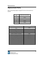
1
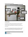
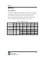
TO-Clean Manual (Version 4.3) 101 Rome Ct. Fort Collins, CO 80526 Ph: (970) 221-9176 F: (970) 221-9364 ©Copyright 2012 by Wasson ECE Instrumentation, Inc. (MG 10/12) All rights reserved worldwide Printed in the United States of America This publication is protected by federal copyright law. No part of this publication may be copied or distributed, transmitted, transcribed, stored in a retrieval system, or transmitted into any human or computer language, in any form or by any means electronic, mechanical, magnetic, manual or otherwise, or disclosed to third parties without the express written permission of Wasson-ECE Instrumentation, Inc., 101 Rome Court, Fort Collins, CO 80524. Disclaimer of Warranty and Limited Warranty This publication is provided “as is” without warranty of any kind. Wasson-ECE Instrumentation, Inc. does not warrant, guarantee, or make any representation regarding the use, or the results of the use, of this publication in terms of correctness, accuracy, reliability, currentness, or otherwise. Further, WassonECE Instrumentation, Inc. reserves the right to review this publication and to make changes from time to time in the content herein without obligation of Wasson-ECE Instrumentation, Inc., to notify any person or organization of such revision or changes. Note to the End User This manual should be read in its entirety, prior to use of the instrument. Once read, please follow the instructions in the “Initial Setup” section of the manual in setting gas pressures and supplying appropriate power to the TO-Clean. This symbol alerts the user to a potentially hazardous situation. The user should refer to this section of the manual before operating the equipment. Important Safety Warnings Parts of the TO-Clean operate at temperatures high enough to cause serious burns. You should always cool the TO-Clean to room temperature before working on the system. If you must perform maintenance on hot parts, use a tool and thermally protective gloves. If the TO-Clean is connected to a power source, even if the power switch is off, potentially dangerous voltages exist. The hazardous parts are shielded by covers. With the covers in place, it should be difficult to accidently make contact with dangerous voltages. Before performing any procedure that requires removal of a cover, disconnect the gas chromatograph from the power source. If the power cord insulation is frayed or worn, the cord must be replaced. Contact Wasson-ECE for a suitable replacement part. The TO-Clean is not designed for use with flammable samples. If using a flammable sample with the TO-Clean, be aware that a leak in the system may cause a fire or explosion hazard. In any application using flammable gases, leak check all connections, lines, and valves before operating the TO-Clean. Always turn off the flammable gas at its source when the instrument is not being used, or before working on the instrument. Insure the TO-Clean vent and vacuum vent are plumbed to a safe location, free of any ignition sources. The TO-Clean is not designed to be used with toxic samples without a secondary ventilation system. If the user must run a toxic gas in the TO-Clean, it should be housed in a ventilated secondary enclosure designed for that purpose (such as a laboratory fume hood). It is the responsibility of the customer to inform Wasson-ECE if the TO-Clean has been used with toxic chemicals prior to any instrument service being performed. When handling any chemicals for use in the TO-Clean, all applicable local and national laboratory safety practices must be followed. This would include, but not be limited to, correct use of Personal Protective Equipment (PPE), correct use of storage containers, and correct handling of chemicals as defined in the laboratory’s internal safety analysis and standard operating procedures. Failure to adhere to laboratory safety practices could lead to injury or death. Any disposal of chemicals must be in compliance with applicable local and national laws. Table of Contents Table of Contents Instrument Description ........................................................................... 1 Product Features ............................................................................................. 1 Operating Specifications .................................................................................. 2 Initial Setup .............................................................................................. 3 Gas Supply ...................................................................................................... 3 Cryogenic Liquid .............................................................................................. 4 Power Requirements ....................................................................................... 4 Hardware Description and Assembly .................................................... 5 Vacuum Pump ................................................................................................. 5 Dewar .............................................................................................................. 7 Humidification Chamber .................................................................................. 9 Vacuum Valve Assembly ............................................................................... 11 Controller Box................................................................................................ 12 Operation................................................................................................ 14 Setting the Oven Temperature – Watlow EZ Zone PM Controller .................. 14 Setting your Watlow Parameters .............................................................................. 15 Autotuning Controllers .............................................................................................. 17 Connecting the Canisters .............................................................................. 18 Connecting 1 Liter Canisters .................................................................................... 18 Software Control ............................................................................................ 18 Diagnostics ............................................................................................................... 19 Table of Contents Method Configuration ............................................................................................... 23 Canister Cleaning ..................................................................................................... 25 Initial Use ...................................................................................................... 27 Safe Shutdown Procedures ........................................................................... 28 Disconnecting the Nitrogen Source .......................................................................... 28 Powering Down the System ..................................................................................... 29 Methods .................................................................................................. 30 Default Method .............................................................................................. 30 Maintenance ........................................................................................... 31 Troubleshooting ............................................................................................. 31 Vacuum Pump ............................................................................................... 32 Dewar U-Tube Traps ..................................................................................... 34 Replacement Parts ................................................................................ 36 Warranty Statement ............................................................................... 37 CE Certification – Declaration of Conformity ...................................... 38 Plumbing Diagram ................................................................................. 39 Instrument Description Instrument Description TO-Clean is a revolutionary canister cleaning system developed by Wasson-ECE Instrumentation. The TO-Clean canister cleaner allows for fully automated canister cleaning. The TO-14/15 compliant TO-Clean system was designed to take the guess work out of canister cleaning. The system has a capacity of twelve, 6-L canisters, increasing your lab’s efficiency. The system is fully automated, allowing the user to start a cleaning cycle and walk away. Using the touch screen controller, up to ten custom methods can be defined and loaded as needed. The system also comes with an automated leak check method to ensure system performance. This provides a high performance system that is easy to use and consistent. An on-board touch screen embedded controller makes system operation as easy as pressing start. The user can define the parameters for each method including: number of cycles, pressure, and soak times. Once the method has been defined, it is saved and is accessible for later use. Product Features EPA Method TO-14/15 compliant 12 canister capacity, expandable to 24 one liter canisters Embedded touch screen controller 40 mTorr vacuum for 12, 6-liter canisters Automated system leak test Electronic valve control Custom-built trays for different canister sizes User defined methods Save up to ten methods Isothermal oven, controllable to 110°C Edwards RV-8 vacuum pump 1 Instrument Description Operating Specifications The TO-Clean was designed to be used according to the following specifications. Any use outside of the intended purpose and specifications of this instrument may result in damage to the system, bodily injury and possible loss of warranty. Feature Specifications TO-Clean Model Number TO-Clean Serial Number TO0108 General Ambient operation temperature Canister/Sample Type Required Gases Nitrogen supply input pressure range Actuation supply input pressure range Required Cryogen Required Water Venting Requirements TO-Clean Power Vacuum Pump Power Operation Weight Dimensions Oven Temperature Range Soak Pressure Range Vacuum Pressure Range Cycle Pressure Time TO-Clean is designed to purge/vacuum sample canisters for cleaning per EPA Method TO-14/TO-15. 5 to 40°C (41 to 104°F) Specially passivated stainless steel canisters (Silco-Can or equivalent)/Ambient Air Samples High purity nitrogen and actuation air 10 - 35 psig max (see page 3 for details) 55 – 60 psig max (see page 3 for details) Liquid argon for dewar HPLC grade water for humidifer Purge vent and vacuum vent should be vented to a safe location 120 VAC, 50/60 Hz, 20A or 220-240V, 50/60Hz, 9.6A 120 VAC, 50/60 Hz, 7.8A or 220-240V, 50/60Hz, 4.0A Continuous 525 lbs (238 kg) 44 ½” H x 49”W x 27” D Room temperature - 110°C 5 psig – 30 psig 40 mTorr – 1000 mTorr 0 minutes – 999 minutes 2 Initial Setup Initial Setup Gas Supply Connect all gas lines to the proper fittings, as described in the Hardware Description and Assembly section. Gas bottle regulators should be high quality two stage regulators. Set the gas bottle pressures leading to the TO-Clean to the following gas pressures: Gas Minimum Quality Maximum Set Pressure Nitrogen or Zero Air Ultra High Purity 35 psig max Note: Nitrogen or zero air pressures greater than 35 psig can damage the vacuum transducer. Valve actuation requires approximately 55 psig dry instrument air or nitrogen. Industrial compressed “house air” is usually inadequate for valve actuation without additional treatment. Water and particulates can damage the actuators. Connect gases as described in the Hardware Description and Assembly section. Wasson-ECE recommends leaving the nitrogen source connected and pressurized unless you are changing bottles. When you need to change bottles, follow the procedures outlined in the Disconnecting the Nitrogen Source section on page 28. Wasson-ECE does not recommend using the same nitrogen source for the valve actuation and the charge pressure lines as improperly disconnecting the nitrogen charge source could allow water to flow into the actuation valve line and cause damage to the electrical components. If the same nitrogen source is used, two 3 Initial Setup regulators will be required to control the pressures within the correct operating range of each line. Cryogenic Liquid The system requires liquid cryogen to fill the 4.3L dewar provided. Wasson-ECE recommends the use of liquid argon from a low pressure dewar or a bulk laboratory source. Caution: Exert extreme caution when working with cryogen to prevent injuries from frostbite, asphyxiation, and explosions. Always wear proper personal protection equipment (PPE) including gloves and eye protection when working with cryogenic liquids. Power Requirements The TO-Clean system and vacuum pump are configured for 120VAC, 50/60 Hz or 220-240VAC, 50/60 Hz. See the Operating Specifications on page 2 for amperage requirements. 4 Hardware Description and Assembly Hardware Description and Assembly Place the TO-Clean on a bench top or on the optional system cart in an area with appropriate electrical outlets and gas supply as described in the previous section. There needs to be enough clearance in front of the TO-Clean to open the door (38”) and also to access the back of the controller box. Note: The TO-Clean weighs 525 lbs (238.1 kg). Do not attempt to lift this system by yourself. Use a mechanical lifting device and secure edges to ensure the system does not tip over. Follow standard safety guidelines when moving this system. Vacuum Pump The TO-Clean comes with an Edwards RV-8 vacuum pump. Unpack the pump and place it on the floor next to the canister cleaner. Attach the vacuum hose to the top of the pump, using the metal clamp, as shown in Figure 1. The oil mist filter and oil ballast have been pre-assembled at the factory and are connected by a short piece of tubing. Unscrew the gray oil ballast cap and screw the oil ballast into the threaded hole until tight. Remove the clear cap from the black mist filter fitting on the pump. Place the oil mist filter on top of the black fitting and secure using the metal clamp. Unscrew the two gray oil caps on the pump and pour the oil that came with the vacuum pump in either of the inlets. There is an oil level window on the back of the vacuum pump. The oil reservoir should be 1/3 – 1/2 full. You should not need the entire bottle for the first fill. Screw the oil caps back on before turning the pump on. 5 Hardware Description and Assembly The pump settings have been set at factory to the values in Table 1. Table 1 – Vacuum Pump Default Settings Pump Setting Description Default Setpoint A higher gas ballast allows the pump to handle Gas Low Flow Ballast (Position I) Mode High Vacuum Selects high vacuum mode over high Selector (small droplet) throughput mode. condensable vapors such as water but also increases the pump ultimate pressure. The pump performs most efficiently when the oil is warm. If cleaning cycles are performed frequently the pump may be left on. For further information on the Edwards pump see the manual and CD included in the shipment. Figure 1 – Vacuum Pump Oil Caps Oil Mist Filter Vacuum Hose to Dewar UTube Mist Filter Fitting Oil Ballast 6 Hardware Description and Assembly Dewar The dewar houses the U-tube where contaminants are trapped. This aids in cleaning the nitrogen entering the system, protects the pump from contaminants in the canisters, and prevents any back diffusion from the pump to the system. Connect the dewar brackets to the right side of the TO-Clean as shown in Figure 2. Slide the dewar into the brackets and place both the vacuum and nitrogen Utubes into the dewar along with the provided insulating cap. Figure 2 - Dewar Bracket Dewar Brackets Attach the vacuum hose from the pump to the dewar U-tube using the metal clamp, as shown in Figure 3. Attach the vacuum hose, which goes to the assembly in Figure 6, to the other side of the dewar U-tube using the metal clamp. 7 Hardware Description and Assembly Figure 3 - Dewar Vacuum Hose Connections Vacuum Hose to Pump Vacuum Hose to Valve Assembly Connect the 1/8” line from the compressed nitrogen regulator to the 1/8” moisture trap provided. Connect the other end of the 1/8” moisture trap to the 1/8” dewar U-tube fitting as shown in Figure 4. Connect the other side of the 1/8” dewar Utube line to the bottom of the humidification chamber, described in the next section. The dewar can be filled with liquid argon once the system has been assembled and leak checked per the procedures in the Leak Testing section on page 21. The 1/8” fittings on the charge gas line need to be disconnected to remove the dewar lid. The user should be able to lift the insulating lid with the vacuum hose connections intact. If the dewar needs to be moved to the liqud argon source, remove one of the screws holding the top strap around the dewar. For safety, it is preferable if a 8 Hardware Description and Assembly liquid argon source can be plumbed to the system. Fill the dewar with liquid argon to three inches below the top, exerting extreme caution not to expose skin to the liquid argon. This should be enough cryogen for a 12 hour period. Place the dewar back on the shelf and re-screw the strap, if necessary. Carefully replace the dewar lid and connect the fittings on the charge gas line. Figure 4 - Dewar with Nitrogen Charge Gas Connection Nitrogen or charge gas through Dewar Nitrogen or charge gas through Dewar Humidification Chamber The humidification chamber is filled with water and humidifies the nitrogen entering the canisters. This aids in removing volatile organic compounds from the canisters. If not already connected, attach the 1/8” nitrogen charge gas tubing from the dewar to the top of the tee on the humidifier cap. Do not remove the check valve between the dewar and humidifier. This prevents water from backing 9 Hardware Description and Assembly into the dewar and freezing the nitrogen charge gas line. Attach the 1/8” tubing from the side fitting on the tee on the humidifier cap to the 1/4” bulkhead labeled “UHP Nitrogen” on the back of the controller box, shown in Figure 7. Note: The maximum pressure of the humidifier is 60 psig. If the nitrogen line exceeds this pressure, the humidification chamber could explode. The user should take care to set the system pressure at the maximum pressure of 35 psig. Figure 5 - Humidification Chamber To “UHP N2” bulkhead on back of controller box To Dewar Nitrogen or Charge gas 1/8” fitting Humidification Chamber Humidification Chamber Strap and Release Clip To fill the humidifier, release the clips on the metal strap around the bottle and remove the metal strap. While supporting the humidifier, angle it away from the TO-Clean and unscrew the PTFE lid. Fill the humidifier about a quarter full with HPLC grade water only. Do not fill more than half full. If contamination from room 10 Hardware Description and Assembly air is a concern, make sure to thoroughly purge the humidifier each time the water is changed before cleaning cans. Vacuum Valve Assembly The vacuum valve assembly is located at the back of the TO-Clean and consists of the vacuum valve and tee fitting, shown in Figure 6. Attach the vacuum valve hose assembly from the dewar U-tube to the bottom of the vacuum valve. If not already connected, attach the 1/8” vacuum valve actuation air line to the 1/8” fitting on the vacuum valve. Attach the 1/8” nitrogen charge line from the bulkhead labeled “To Tee Fitting”, located on the back of the controller box, to the tee on the vacuum valve assembly. 11 Hardware Description and Assembly Figure 6 - Vacuum Valve Assembly Nitrogen charge gas – to bulkhead labeled “To Tee Fitting” Vacuum Valve Tee Fitting Valve Actuation Air – to bulkhead labeled “Air or N2 – 60 psig Max” Vacuum Hose to Dewar U-tube Controller Box The controller box, located at the upper right side of the TO-Clean, houses the electrical components, including the heater controller and the touch screen controller. Operation of these components is described in the Operation section of this manual. There are five 1/8” bulkheads located on the back of the controller box, shown in Figure 7. If not already connected, attach the tubing shown in Figure 6 “Valve Actuation Air” and “Nitrogen Charge Gas” to the bulkheads labeled “Vacuum 12 Hardware Description and Assembly Valve” and “To Tee Fitting”, respectively and connect tubing from the humidifier shown in Figure 5 to the bulkhead labeled “UHP Nitrogen”. You will need to connect actuator gas to the bulkhead labeled “Air or Nitrogen 60 PSIG Max” and the bulkhead labeled “Purge Vent” to a proper vent location. Troubleshooting note: The vacuum valve requires pressures between 55-60 psig to actuate. Gas pressures outside of this range will either fail to actuate the valve or cause damage to hardware components. Figure 7 - Controller Box – Back Plug the power cable to the back of the controller box and to the appropriate electrical outlet. The power switch is located on the back of the control box. Set the power switch to the “On” position. The fan on the back of the controller box should start running and the heater and control screen on the front of the controller box will turn on. 13 Operation Operation To start using the system, the TO-Clean and the vacuum pump must be powered on. The power switches are located on the back of the controller box and the back of the vacuum pump. Once these have been switched on, the following sections can be used to set the oven temperature and configure cleaning methods. Setting the Oven Temperature – Watlow EZ Zone PM Controller The oven temperature is controlled by the Watlow controller located on the front of the control panel. Turn on the TO-Clean to power up the controller. Make sure the oven door is closed to operate the controller, as a safety latch is installed to shut off heaters when the door is open. Set the controller temperature to the temperature at which you wish to clean the canisters. To change the operating temperature, press the [▼] or [▲] arrow keys on the Watlow controller. The lower display will show the set temperature; the upper display will show the actual temperature. The oven’s maximum temperature is 110°C. Note: If you are using Restek canisters, the blue Parker valves can withstand heating to 250°C, but the gauges on the 3-way valves can only be heated to 80°C. Please verify what type of valve/gauge is on the canister before setting the oven temperature. The Watlow parameters have been factory set. If you need to re-set these parameters, follow the instructions described below. Complete information about the Watlow controller and all default values can be found in the Watlow Series EZ Zone PM PID Controller User’s Manual on the CD included with the shipment. 14 Operation Setting your Watlow Parameters 1. To enter the Setup Menus, press and hold both [▼] and [▲] keys until the lower display says [SEt]. The upper display should give you several different options. Use the [▼] and [▲] keys to scroll through these options. 2. Scroll to [gLbL] and hit the Advance key []. [C_F] should show up in the lower display. The upper display should be [C]. Use the[▼] and [▲] keys to scroll through the options for the upper display. 3. Hit the [∞]to return to the [gLbL] display. 4. Use the [▼] and [▲] keys to scroll to [Ai] in the upper display and hit the Advance []key. 5. Keep pressing the Advance [] key until [SEn] is in the lower display. 6. Hit an arrow key to scroll to [tC] in the upper display. 7. Hit the Advance [] key and scroll to [Lin] in the lower display. 8. Use the [▼] and [▲] keys to scroll to [H] in the upper display. 9. Hit the [∞] key two times. The upper display should show [Loop] (use the [▼] and [▲] keys to adjust the parameter if it is not set to [Loop]). 10. Press the Advance [] key until [L.SP] is in the lower display. The upper display should show [0] (use the [▼] and [▲] keys to adjust the number if it is not set to [0]). 11. Press the Advance [] key until [h.SP] is in the lower display. The upper display should show [110] (use the [▼] and [▲] keys to adjust the number if it is not set to [110]). 12. Press the [∞] key until [Loop] is in the upper display. 13. Press the Advance [] key until [t.tUn] is in the lower display. The upper display should show [yES] (use the [▼] and [▲] keys to adjust the parameter if it is not set to [yES]). 15 Operation 14. Press the [∞] key until [Loop] is in the upper display. Use the [▼] and [▲] keys to scroll to [Ai] in the upper display. 15. Press the Advance [] key until [Ai] is in the lower display. The upper display should be set to [2]. 16. Press the Advance [] key to scroll to [SEn] in the lower display. 17. Use the [▼] and [▲] keys to scroll to [r0.1H] in the upper display. 18. Press the Advance [] key to scroll to [rt.L] in the lower display. Use the [▼] and [▲] keys to scroll to [2] in the upper display. 19. Press the [∞] key to get back to [Ai] in the upper display. Use the [▼] and [▲] keys to scroll to [dio] in the upper display. 20. Press the Advance [] key to scroll to [dir] in the lower display. 21. Use the [▼] and [▲] keys to scroll to [in] in the upper display. 22. Use the Advance [] key to scroll to [LEv] in the lower display. Use the [▼] and [▲] keys to scroll to [LoW] in the upper display. 23. Use the Advance [] key to scroll to [Fn] in the lower display. Use the [▼] and [▲] keys to scroll to [oFF] in the upper display. 24. Press the [∞] key to get back to [dio] in the upper display. 25. Use the Advance [] key to scroll to [dir] in the lower display. Use the [▼] and [▲] keys to scroll to [OtPt] in the upper display. 26. Use the Advance [] key to scroll to [Fn] in the lower display. 27. Use the [▼] and [▲] keys to scroll to [ALM] in the upper display. 28. Use the Advance [] key to scroll to [Fi] in the lower display. Use the [▼] and [▲] keys to scroll to [1] in the upper display. 29. Use the [∞] key to get back to [dio] in the upper display. Use the [▼] and [▲] keys to scroll to [ALM] in the upper display. 30. Press the Advance [] key to scroll to [A.ty] in the lower display. Use the [▼] and [▲] keys to select [Pr.AL] in the upper display. 31. Press the Advance [] key to scroll to [Sr.A] in the lower display. Use the [▼] and [▲] keys to scroll to [Ai] in the upper display. 16 Operation 32. Press the Advance [] key to scroll to [iSA] in the lower display. Use the [▼] and [▲] keys to scroll to [2] in the upper display. 33. Press the Advance [] key to scroll to [A.hy] in the lower display. Use the [▼] and [▲] keys to get to [1] in the upper display. 34. Press the Advance [] key to scroll to [A.L9] in the lower display. Use the [▼] and [▲] keys to scroll to [AL o] in the upper display. 35. Press the [∞] key until the Main display appears again, showing the temperatures in the upper and lower displays. 36. To enter the Oper Menus press and hold both [▼] and [▲] until the lower display says [OPEr]. Use the [▼] and [▲] keys to scroll to [ALM] in the upper display. 37. Press the Advance [] key until the lower display shows [A.hi]. Use the [▼] and [▲] keys to change the upper display to [300]. 38. Press the [∞] key until the Main display appears again, showing the temperatures in the upper and lower displays. Autotuning Controllers You may occasionally need to perform an autotune to ensure the Watlow controller is working optimally. Before autotuning, make sure the controller hardware is installed correctly, and the sensor type and function, along with the scale setting, are set in the configuration parameters. First, enter the desired set point or one that is in the middle of the expectant range of what needs to be tuned. Next, turn on the autotuning by following the steps below: 1. From the Main display, press the Advance [] key until the lower display shows [AUt1]. Use the [▼] and [▲] keys to change the upper display to [yES]. When autotuning is working, the display will flash back and forth between the current display and the upper display 17 Operation showing [tUn1] and the lower display showing [Attn]. Once autotuning is finished, the controller will start controlling at the normal set point, using the new parameters. 2. Press the [∞] key until the Main display appears again, showing the temperatures in the upper and lower displays. Connecting the Canisters Place the 6 liter canisters upside down in the slots in the oven shelves and connect them to the ¼” Swagelok fittings provided with the steel flex tubing. It is easiest to start loading cans on the top shelf in the back and work forward and down. It is helpful to make sure the valves are facing forward when connecting the canisters. Do not open the valves until all positions are connected so the canister contents can be properly directed to the vent. If there are any positions that are unused ensure that position is plugged with the provided ¼” Swagelok plug. Connecting 1 Liter Canisters If the optional upgrade to 24 - 1 Liter Canister capacity was purchased, the system will include 12 sheet metal inserts. These are removable and are fastened to the standard rack with four screws each. The 1 liter canisters are placed upside down over the opening in the insert. The steel flex tubing will have a removable tee with two connections to handle double the canisters. To convert back to 6 liter canisters, remove the metal inserts by unscrewing the 4 screws, and remove the tees from the flex tubing lines. Software Control When the controller is powered on using the power switch located on the back of the controller the user is presented with the Start Menu (Figure 8) which allows 18 Operation the user to select one of three options: Configure Methods, Diagnostics, or Clean. Figure 8 - Start Menu Diagnostics The control software allows the user to diagnose the system for potential problems. By selecting Diagnostics from the Start Menu the user can leak check the system and actuate valves in the system to diagnose valve problems. The Diagnostics screen (Figure 9) allows the user to select Valve Control or Leak Test the system. 19 Operation Figure 9 - Diagnostics Valve Testing All system valves can be tested using the Valve Control menu (Figure 10). This menu allows the user to actuate the Pressure Valve, Vent Valve, and Vacuum Valve. When the valve is actuated the user will hear the valve switch. If the valve switch is not audible then contact the Wasson-ECE service department for support at (970) 221-9179. Figure 10 - Valve Control 20 Operation Leak Testing Before running cleaning cycles, the system should be leak checked. If the system is not leak tight, achieving lower vacuum will be difficult if not impossible. First, the charge gas line should be tested for leaks using a pressure decay test. This is done by adjusting the regulator to pressurize the line to 35 psig. Once the pressure gauge reading has stabilized, close the regulator. If the gauge pressure remains constant after ten minutes, the charge gas line is leak tight. If the gauge pressure does not remain constant, check the fittings (between the regulator and V3 on the plumbing diagram) and perform this test again. Once the charge gas line is tested the rest of the system can be tested for leaks using the Leak Test Menu (Figure 11). From the Diagnostics menu select Leak Test. Using the arrows choose a desired charge pressure and a soak time. If the system holds pressure to +/- 0.4 psi the system is considered leak tight and will pass the test. If the system fails the leak test secure all fittings and run the leak test again. The status of the leak test is displayed in the Leak Test menu. The leak test feature can also be used to ensure the canisters have been attached properly and that none of the canister fittings are loose before cleaning. 21 Operation Figure 11 - Leak Test Menu As the leak test is performed, the Leak Test Status screen (Figure 12) is displayed. The leak test can be stopped at any time by pressing “Cancel”. Figure 12 - Leak Test Status 22 Operation Method Configuration From the Start Menu select Configure Methods. In the Configuration screen (Figure 13) the user is able to configure the method including Cycle Setup, Pressure Setup, and Canister End State. Figure 13 - Configuration Screen To configure a method, start by selecting Cycle Setup. In the Cycle Setup screen (Figure 14), the user can select the number of cycles desired by touching the up and down arrows. Notice that for each cycle, both the Low and High Pressure Cycle Times can be adjusted. Each cycle can have different low and high pressure cycle times. Once the desired settings have been achieved select Accept to return to the Configuration screen. 23 Operation Figure 14 - Cycle Setup From the Configuration screen (Figure 13) select Pressure Setup. In the Pressure Setup screen (Figure 15) cycle set the charge pressure and the vacuum pressure for each cycle. Figure 15- Pressure Setup Select Accept to return to the Configuration screen (Figure 13). Before the method is saved choose a Canister End State. The canister end state allows the user to select if the canisters will be under vacuum or under pressure at the end 24 Operation of the cycle. If the canisters will need to be tested for certification after cleaning, select Pressure. The pressure of the canister will be left at the Charge Pressure of the last cycle. If the canisters will need to be readied for sampling then select Vacuum. The canisters will be left at the Vacuum Pressure of the last cycle. This pressure is set in the Pressure Setup screen (Figure 15). After the method has been configured the user can save and name the method using the keyboard provided in the Save Method screen (Figure 16) by choosing Save from the Configuration (Figure 13) screen. Type the name of the new method and choose Save. After saving the method the software returns to the Configuration screen. From the Configuration screen choose Accept. This will return the user to the Start Menu (Figure 8). Figure 16 - Save Method Screen Canister Cleaning In the Start Menu (Figure 8) select Clean. The Clean Menu (Figure 17) displays the Method that is currently loaded. To start cleaning using the loaded method 25 Operation parameters, select Clean. If no method is listed as loaded or a different method is desired, select Load Method. Figure 17 - Clean Menu In the Load Method screen (Figure 18) scroll to the desired method using the arrows on the side of the screen and choose Load. Figure 18 - Load Method Screen 26 Operation Once the method has been loaded the user is returned to the Clean Menu and the loaded method is displayed on the screen. The method has now been loaded and is ready to clean. Select Clean. The system will start to run the method and the Cleaning status screen (Figure 19) will be displayed. Cleaning status will display the status of the system including number of cycles remaining, cycle status, pressure and time remaining for the current cycle. Using the Cancel button the cleaning can be cancelled at any time. Figure 19 - Cleaning Status Initial Use The TO-Clean system components have been tested to be free of contamination. However, contamination can occur during transport, from exposure to laboratory air, or from impure water in the humidifier. Before using the system for the first time, it is recommended that the user purges the system extensively with humidified air or nitrogen before cleaning canisters. This can be done by setting up a method with multiple cycles and running the method with the manifold capped. 27 Operation This procedure is also recommended anytime the water in the humidifier is changed or the system has been exposed to room air for an extended period. Safe Shutdown Procedures Disconnecting the Nitrogen Source To ensure uninterrupted operation of the TO-Clean, the following procedures must be followed when reducing nitrogen supply pressure or changing nitrogen bottles. Failure to follow these procedures may result in water from the humidifier backing into the dewar U-tube and freezing. 1. After the last cleaning cycle is finished, reduce oven temperature setpoint to 25°C. Open the door for faster cooling. 2. Once the oven is sufficiently cooled, close all the canister valves. 3. Close the valve on the nitrogen bottle. 4. On the Start Menu, select Diagnostics. 5. On the Diagnostics menu, select Valve Control. 6. On the Valve Control menu, click the Vent Valve “On”. This will bring the manifold and lines between V3 and V1 to atmospheric pressure. 7. Click the Pressure Valve “On”. You should hear nitrogen flowing out of the purge vent. 8. Once the regulator pressure reads “0”, close the regulator. 9. On the Valve Control screen click the Vent Valve and Pressure Valve “Off”. 10. Replace the nitrogen bottle. 11. Open the nitrogen bottle valve and set the regulator to desired pressure, 35 psig maximum. 12. The system is now ready to run cleaning cycles. 28 Operation Powering Down the System 1. After the last cleaning cycle is finished, reduce the oven temperature setpoint to 25°C. Open the door for faster cooling. Do not touch oven components until they are sufficiently cooled. 2. Once the oven is sufficiently cooled, close all the canister valves. 3. If you are planning on disconnecting the nitrogen source follow the instructions in the previous section. 4. Shut off power to the TO-Clean using the switch on the back of the controller box, shown in Figure 7. 5. Shut off the vacuum pump using the power switch located on the back of the pump. 29 Methods Methods Default Method The TO-Clean is designed around EPA Method TO-15 and comes with a Default method based on these parameters. The table below shows these settings as well as the EPA recommended method for non-heated cleaning cycles. Customers may adjust these parameters to create methods for their specific needs, as described in the Method Configuration section on page 23. Table 2 – Method Parameters Method Canister End State Number of Cycles Default Vacuum 1 TO-15 Recommended Procedure without Heating Vacuum 3 Cycle # Low Pressure Cycle Time (min) High Pressure Cycle Time (min) Charge to Pressure (psig) Vacuum Pressure (mTorr) 1 60 5 30 50 1 60 30 50 2 60 30 50 3 60 30 50 Not specified Not specified Not specified 30 Maintenance Maintenance This section can help you solve operating problems that may arise while operating the TO-Clean. If you cannot solve the problem, call the Wasson-ECE Instrumentation Service Department at (970) 221-9179. Troubleshooting 31 Maintenance Item Symptoms Recommended Action Setpoint is too low. Although the software can set the vacuum pressure to 10 mtorr, the vacuum pump is not strong enough to achieve this setpoint. Change vacuum settings to 40 mtorr. There is a system leak. Run the Leak Test method. If there is a leak, check canister connections and fitting in controller box. If Leak Test does not indicate a leak, check the connections of the PVC tubing. Vacuum System is not reaching vacuum setpoint. There is water in the U-tube. Remove U-tube from dewar and thaw in a properly vented location. The pump oil needs to be replaced. Follow procedures in the vacuum pump manual. The vacuum valve is not actuating. Use diagnostics screen to turn on the vacuum valve. There should be a loud click when it actuates. If there is no sound, check the pressure of the actuation air. If the valve is still not working call Wasson-ECE for a replacement. The valves are clicking but won’t reach pressure set point. The charge pressure is not high enough or the pressure setpoint is too high. The system turns the pressure valve on and off as it gets closer to the pressure setpoint. The charge pressure must be set at at least 5-10 psig above the pressure setpoint or the valve will just keep clicking on and off. Please note that the setpoint should not be greater than 30 psig as the system can only handle a maximum of 35 psig. Pressure The valves are not clicking but the system is not reaching the pressure setpoint. Charge gas cylinder is empty or regulator is turned off The U-tube or check valve is frozen. Remove U-tube or check valve from the dewar and thaw in a properly vented location. The pressure transducer is not reading correctly. Call WassonECE for assistance. Vacuum Pump A periodic maintenance and inspection schedule of the vacuum pump can lead to increased uptime, reliable results, and longer instrument lifetime. Refer to Table 3 for the recommended maintenance schedule for the vacuum pump. Maintenance instructions are described below. For further information refer to the Edwards Instruction Manual CD which is included with the system. 32 Maintenance Table 3 – Recommended Maintenance Schedule for Vacuum Pump Maintenance Frequency Check oil level Replace the oil Inspect and clean inlet filter Inspect and clean gas-ballast control Clean oil level window Clean motor fan-cover and enclosure Weekly Every 3000 hours of operation Yearly Yearly Yearly Yearly Check Oil Level The user must ensure that there is sufficient oil in the vacuum pump. This can be quickly monitored using the oil level window on the back of the pump. If you need to add more oil, follow the steps in the Hardware Description and Assembly section of this manual on page 5. Replace the Oil 1. Operate the pump for ten minutes to warm the oil. 2. Turn the pump “Off”. 3. Place a block under the front of the pump to tilt it toward the drain in the back. 4. Unscrew one of the oil caps on the top of the pump. 5. Place a vessel under the drain and remove the drain plug. 6. Replace drain plug and fill the pump with new oil as described in the Hardware Description and Assembly section of the manual on page 5. 7. Replace oil caps and remove block before operating the pump. Inspect and Clean the Inlet Filter 1. Disconnect the Vacuum Hose to Dewar U-tube from the pump inlet port (Figure 1). 33 Maintenance 2. Remove the filter and O-ring and inspect for cleanliness. 3. If needed, remove the O-ring from the filter and wash the filter with a proper cleaning solution and allow it to dry. Do not let the O-ring come into contact with the cleaning solution. 4. Re-assemble the filter, O-ring, and Vacuum Hose to Dewar U-tube. Inspect and Clean the Gas Ballast Control 1. Remove the oil ballast (Figure 1) from the top of the pump. 2. Wipe with a clean dry cloth and check that the air hole is not blocked. 3. Screw the oil ballast back into place. Clean Oil Level Sight Glass 1. Drain the oil as described above. 2. Undo the two screws at the top and bottom of the oil level window and remove the bezel, window, and O-ring. 3. Clean the screws, bezel and window with a proper cleaning solution. 4. Wipe the O-ring with a dry cloth. 5. Re-assemble the oil level window. 6. Fill the pump with oil and check for any leaks through the window. Clean the Motor Fan-Cover and Enclosure 1. Turn the pump OFF and disconnect from the electrical supply. 2. Use a dry cloth and soft brush to remove dirt and deposits from the fancover and enclosure. Dewar U-Tube Traps 34 Maintenance The Vacuum U-tube and Pressure U-tube housed in the Dewar will periodically need cleaning. To do this: 1. Remove the 1/8” tube fittings on either side of the Pressure U-tube. 2. After the last cleaning cycle is finished, reduce oven temperature setpoint to 25°C. 3. Once the oven is sufficiently cooled, close all the canister valves. 4. Remove the vacuum hoses on either side of the Vacuum U-tube by unscrewing metal clamps. 5. Carefully remove U-tubes from dewar cap. 6. Allow the traps to come to room temperature in a properly vented location. 7. Pour out any moisture in the U-tubes. 8. Allow to dry completely. They may also be placed in a heater to facilitate removal of organic components. 9. Replace dewar cap and attach U-tubes to respective fittings. This should be done on a daily basis (or more frequently, if needed). 35 Replacement Parts Replacement Parts Refer to the plumbing diagram on page 39 for the valve that needs to be replaced. Valve Wasson-ECE Part Number 1 56156 2 56154 3 56154 Vacuum Valve 25564 Item O-Ring Seals for Vacuum Hose and Tee Fitting ¼” Nuts with caps ¼” Vespel ferrules Tee Fitting, NW25 Metal Clamps for Vacuum and Tee Pressure Transducer, 0-50 PSIG Pressure Transducer, 15 mTorr PVC Vacuum Tubing – 6 ft, 3 ft Humidifier Humidifier cap Dewar, Pyrex Brand Glass, 4300 mL ½” Stainless Steel U-tube, vacuum trap 1/8” Stainless Steel U-Tube, pressure trap Edwards RV-8 Vacuum pump Edwards Oil, 1 quart Edwards Oil Mist Filter Wasson-ECE Part Number 25566 12910-001 1499 25572 25570 25560 25562 25574-003 25568-019 25568-020 25568-022 A2552-004 A2552-002 70218 70487 70219 36 Warranty Statement Warranty Statement Wasson-ECE provides quality analytical systems that are designed, tested and warranted to perform in a reasonable manner consistent with the performance criteria as detailed in the Quotation from which the system was purchased. The warranty includes all materials provided as part of the system such materials originating with Wasson-ECE, Agilent Technologies, or any other “third-party” components incorporated into the solution and identified on the Quotation. Wasson-ECE analytical systems are warranted to perform to design specifications for a period of one year after shipment from the factory in Colorado. Both materials and labor are included in the warranty in North America where the sale is directly from Wasson-ECE to the customer who is the end user. Outside of North America, only materials are warranted; labor is the responsibility of local distributors or other resale agents. This warranty excludes the end user’s operation of the systems in a manner outside of their design specifications. Examples of this misuse include, but are not limited to: The application of inappropriate samples Over temperature of ovens, columns, or valves Low quality carrier gas, or out of carrier gas Particles, precipitates, or heavy liquids introduced Power fluctuations such as over voltage or off frequency Method loss, corruption, or modifications not authorized Fire or mechanical damage from the environment Damage from transportation outside of contracted scope Revised August 1, 2007 37 CE Certification – Declaration of Conformity CE Certification – Declaration of Conformity 38 Plumbing Diagram Plumbing Diagram 39