1
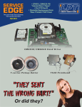
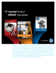
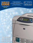
SERVICE EDGE The Laser Printer Tech Quarterly from Liberty Parts Team Fall 2014 THIS ISSUE: • LPT: a PO Processor Partner • 5200 Fuser Drive Replacement •Menus in the M600 • CP6015 Fuser errors • 50 Errors explained PARTS IN SPACE! with arzno wrk SERVICE EDGE, FAL L 2014 NEW PRODUCT Fuser Drive Asm for LJ 5200 available LPT now offers two solutions for a noisy 5200 printer. As with many laser printers, the HP LaserJet 5200 can become noisy when the gears of the fuser drive asm start to wear out. We at Liberty Parts Team have offerred a kit containing these four gears, KIT-5200-GR. Now we are offering the complete fuser drive asm, RC1-7401. Replacement instructions can be found on the next page. COMPANY NEWS LPT Partners With PO Processor HP LASERJET 5200 FUSER DRIVE ASM NOW AVAILABLE (RC1-7401) PO processor is e-automate addon software designed to help reduce time and labor in the purchasing process. While there are costs involved, its timesaving benefits makes it popular with larger service companies. To learn more, talk to your Liberty Parts Team rep. LPT SERVICE EDGE is the quarterly laser printer tech bulletin of Liberty Parts Team Inc. Editor-in-Chief: David K. Reinke Editor: Robert Reinke To order HP, Lexmark, Oki, & Samsung printer parts, call Liberty Parts Team: 888-444-8778. Writers: Dennis Kosterman, R. Reinke ©2014 Liberty Parts Team, Inc. 3 LIBERTY PARTS TEAM 888-444-8778 PRINTER REPAIR ARTICLE Replacing the 5200 Fuser Drive The following instructions will help you replace either the complete fuser drive gear asm or just the gears of that asm. This will cure any grinding noises you may be experiencing. 1 Right Cover. Simply slide the right cover toward the back of the printer to remove it. 2 Lower Back Cover or Duplexer. a Duplexer: If the printer has a duplexer, remove it by pulling it out (at the back of the printer) until it stops, then lifting slightly and pulling it out the rest of the way. b Lower Back Cover: If there is no duplexer, remove the lower back cover by inserting your finger into the hole and pulling toward you. 3 Face-Up Bin. a Open the face-up bin and loosen two recessed screws (Figure A). Note that these are captive screws and cannot be completely removed. The screw on your left will be easier to access if the faceup bin is opened all the way. To do this, first release the fuser nip (the black plastic section of the bin) by slightly closing the bin and then pulling the two sections apart. Now the face-up bin will open all the way. b Once the screws have been loosened, close the bin, grasp the bottom of it, and gently pull out and up to remove it. 4 Top Cover. a Remove two screws in the back (Figure B). b Open the print-cartridge door, remove two more screws in the front (Figure E), and release three retaining tabs – one each on the left, center, and right, along the front edge of the cover (Figure D shows the rightmost retaining tab). 4 SERVICE EDGE, FAL L 2014 c Now you should be able to lift the cover off of the printer. Before you can get it very far, though, you will have to unplug the display cable on the right side (Figure C) and unwind it from the cable guides on the cover. 5 Left Cover. a Removing the left cover is accomplished by releasing five retaining tabs in the proper order: 1 in the center of the top edge (Figure F); 2in the lower left rear corner (Figure G); 3in the tray 2 cavity, about 5 inches in from the front of the printer; 4*under the rear end of the handle; 5*under the front end of the handle. (*These last two are accessed from the bottom of the printer, and are shown in Figure H). b Once all five tabs are released, the cover can be easily lifted off, rotating it as in Figure I. 6 Fuser. a Remove two screws (at the top, just below the white plastic of the delivery asm), one on each side, and pull the fuser straight out the back. 7 Fuser Drive Asm. a The black plastic at the upper front corner of the fuser drive asm has two arms attached to it, one on the outside of the printer (Figure J) and one on the inside (Figure K). Use a needle nose pliers to detach both arms from the captive plastic. b Now remove seven screws (Figure L) and pull the fuser drive asm away from the printer. Be careful – several of the gears on the inside of this asm are not captive and can fall off if it is tilted the wrong way. For best results, keep the inner surface tilted upward. 8 Fuser Drive Gears (optional). a If you opt to replace only the gears, you will have to remove them from the drive asm. Figure M shows the inner surface of the drive asm with the four gears. The two outer gears can simply be lifted off of their shafts. To remove the two inner gears, first remove the spring-loaded black plastic piece that covers them. Note that all four gears are asymmetrical – i.e., there is a right way and a wrong way to install them. Note the proper orientation of each gear before removing it, and make sure to install the new gear with the same orientation. You may also want to apply some grease to the gears (the gears are pre-greased in the full drive asm, but not in the gear kit). LPT has gear grease available (part number GREASE-GEAR-A). Reverse the above steps to re-assemble the printer. Important Note: When re-installing the fuser drive asm, make sure that the black plastic part of the asm gets properly coupled to the small white pin in the printer body. The coupling controls the fuser entrance flap, which should rotate up when the front door is closed. Figure N shows this coupling from the left side of the printer; Figure O shows it from the rear with the flap up; Figure P shows the rear view with the flap down. Note that the fuser is removed in these photos. If the black plastic and the white pin are not coupled properly, this flap will always be down, causing print quality issues and paper jams. LPT 5 LIBERTY PARTS TEAM 888-444-8778 LASER THEORY The 50 Error a hot roller (sleeve) and a pressure roller a ceramic heating element thermistors thermal switch 6 Temperature control during the laser printing process is essential: too hot, and the paper may scorch; not hot enough, and the toner may be incompletely fused. To keep the temperature within the proper range, fuser heat sensors inform the controller board of abnormalities. The controller then instructs the power supply to send or not to send current to the fuser heating element. The 50 error arises when an HP laser printer is unable to maintain the proper fuser temperature (Lexmark printers show 920-925). The following are the possible causes. Fuser. The common cause of 50 errors is the fuser, which would need to be replaced. During the print job, the paper enters the fuser and is pressed between a solid rubber pressure roller and a hot roller made of flexible material or metal. Inside the hot roller are • a heating element, which is either a lamp or a ceramic strip that is heated by power supply voltage • a thermistor to provide temperature feedback to the controller. It is a temperature-sensitive resistor that rides on the inner surface of the hot roller. As the roller temperature rises and falls, so does the voltage across the thermistor. • a thermal fuse or thermal switch protects the fuser from dangerous overheating by opening and interrupting current flow if the temperature gets too high. The basic hot roller/pressure roller construction is common to all fusers, but larger models may have more than one heating element, thermistor, and thermal switch. Power Supply. The power supply, getting instructions from the controller, applies line voltage to the fuser’s heating element. The power supply was a major cause of 50 errors with the ven- SERVICE EDGE, FAL L 2014 Fuser Heating Feedback Loop erable LJ 8150, but in general it has been a much less common cause than the fuser. Controller. The controller board monitors the temperature-sensing elements and switches the power supply on and off as needed to keep the fuser temperature within the proper range. This board goes by various names: in an HP printer, it will typically be called either a dc controller board or an engine controller board (ECU); in a Lexmark printer, it is usually known as the engine board or system board. There are a few printer models where the power supply and controller are merged into a single board, and also some that have multiple power supplies. Bad Connection. Rarely, a bad connection between the fuser and controller, controller and power supply, or power supply and fuser will cause 50 errors. External Cause. A line voltage problem external to the printer can cause 50 errors. For instance, too many devices can overload a single circuit, with the result that the printer cannot get enough current to heat the fuser sufficiently. Exceptions and Additions. •In the Color LaserJet 3000/3600/3800/CP3505, there is a common problem with 50.2 errors only when printing envelopes. We have never found a definite solution to this, but we believe it to be a firmware issue rather than a hardware issue. •Heating element failure in the LaserJet P4014, P4015 and P4515 can cause hanging with "Processing Job" on the display, motor delays and irregularity and unfused print, without showing a 50 error. •The 4200/4300 family may also experience irregular motor behavior instead of showing a 50 error in the event of heating element failure. Additionally, installing the wrong fuser causes 50 errors. •The 9000, in the event of a fuser or power supply problem, can take a long time for its "Warming Up" state without showing a 50 error. •The P3015 can get a 50.3 error from a stuck swing gear in the fuser drive area. Wiggling or a drop of oil on the pivot arm can fix this. In conclusion, the fuser and/or power supply are by far the most common causes, and we usually recommend replacing one or both of these to cure such errors. LPT 7 LIBERTY PARTS TEAM 888-444-8778 PRINTER REPAIR ARTICLE The CP6015/CM6030/40 fuser The CP6015 fuser has the most complex temperature maintenance system we have seen, with three heating elements, three corresponding thermoswitches, and four thermistors. One of the heating elements heats the center of the hot roller, another heats the ends, and a third heats the pressure roller, which is unusual. A thermistor can be found at each end of the the hot roller and the pressure roller. So far, all of these things are part of the fuser, so the main strategy for dealing with a 50 error is still to replace the fuser. However… This printer introduces a new heat detection element: the thermopile. There are two of them contained in a single assembly that is mounted near the middle of the hot roller. Their purpose, according the the manuals, is the detection of the temperature at the middle of the fuser rollers. This assembly is a potential cause of fuser errors. Replacing the Thermopile 1 Open the right door and remove the fuser by rotating the two blue locking levers upward, and then grasping the blue handles and pulling (Caution: the fuser may be hot). 2 Remove one screw and release one tab, both on the right end of the thermopile asm, pull it partway out, and disconnect one cable on the back. Reverse this process to re-assemble. The following are the parts that can cause a 50 error in the CP6015, CM6030/40 in order of approximate probability. • Fuser (CB457A) • Fuser Power Supply (RM1-3218) • Thermopile Case Asm (RM1-3232) • DC Controller PCA (CP6015: Q3931-67930; CM6030/40: RM1-6642) • Bad connections between two or more of the above • External power issues (current overload, etc.) 8 LPT SERVICE EDGE, FAL L 2014 PRINTER REPAIR ARTICLE Menus in the HP LaserJet M60x The restructured menus on the HP M600 series and other new printers have proven disorientating to many techs. There are three menus: the main menu, the service menu, and the preboot menu. This article will help you find the most common menu functions quickly. Before we begin, we should address the peculiar power-on behavior of the M600. Instead of the immediately showing a logo and initialization activity, the M600 display remains dark for about 20 seconds after the printer is powered on (See Fig A). Some customers were worried that this uncustomary delay might be caused by a bad formatter, but no, that is just the way these printers operate. A. THE DISPLAY AT POWERUP Main Menu Pressing OK at the Ready screen, reveals the Main Menu (Fig. B). Sign In The first item is Sign In, but signing in isn't necessary unless the administrator set a password or you need to access the Service Menu. Trays: Tray Size and Type Adjusting paper size and type is done under Trays. Note that Tray Size for cassette trays (tray 2 or tray 3) is “read only,” since this is determined by the physical set-up of the tray itself. For the MP tray (tray 1), both size and type are selectable in the menu. These are normally both set to Any unless you want to dedicate this tray to one specific paper size/type. B. READY SCREEN & MAIN MENU Manage Supplies: Maintenance Reset Manage supplies lets you change supply level messages and settings. Here is how the maintenance reset is done. 1 At the Ready screen, press OK. 2 With Manage Supplies, selected, press OK. 3 Select Reset Supplies and press OK. 4 Select New Maintenance Kit and press OK. 4 Select Yes and press OK. This clears the message and resets the count. Administration: Reports (Fig. C) Many familiar reports and functions can be found under Administration. We will look at a select few, starting with reports. 1 At the Ready screen, press OK. 2 Scroll down to Administration and press OK. 3 Scroll down to Reports and press OK. 4 Scroll down to Configuration/Status Pages and press OK. 5 Scroll past the initial Print command, and you will find eight different types of reports listed. 6 Select a report. A check mark appears next to your selection. Se- C. PRINTING REPORTS 9 LIBERTY PARTS TEAM 888-444-8778 lect more reports if desired. 7 Scroll back to the top and select Print. It will then print your selections. Administration…Adjust Paper Types (Fuser Temp. Changes) Unlike most previous HP monochrome printers, this series does not allow direct fuser temperature adjustment. It appears to automatically adjust for certain paper types – for example, it will run the fuser hotter if the paper type is “Heavy” or “Envelope”. However, like some color printers, it does allow you to cheat to some extent by setting the printer to treat a given paper type as if it were a different type. To see how this works, suppose you want to raise the fuser temperature for “plain” paper. 1 At the Ready screen, press OK. 2 Scroll down to Administration and press OK. 3 Scroll down to General Settings and press OK. 4 Scroll down to Print Quality and press OK. 5 Scroll down to Adjust Paper Types and press OK. You will get a list of all possible paper types. For this example, select “Plain”, and then “Print Mode”. You will see a list of modes, for the most part corresponding to different paper types. By choosing a different mode (the default is “Normal mode”), you will change the way the printer treats plain paper. For example, if you select “Cardstock mode”, the printer will use the fuser temperature, print speed, etc. that it would normally use for cardstock whenever you print on plain paper. You may have to experiment with these settings to get the best performance. D.SERVICE MENU ACCESS Service Menu: Event Log, Page Counts, Serial No. Resets (see Fig. D) In the service menu, you can view or clear the event log, reset the page count (called “Mono Cycle Count” in this menu), or reset the printer serial number if it has been lost. Getting to the service menu is a bit different than on most other HP printer models. It is not accessed through a power-on sequence, but it is not a top-level menu, either. 1 At the Ready screen, press OK. 2 Scroll down to Device Maintenance and press OK. 3 Scroll down to Service and press OK. 4 Scroll down to Service Access Code and press OK. 5 Enter 10060311. The M601, M602 & M603 all use this PIN code. (NOTE: The PIN codes given in the Service Manual are incorrect.) Preboot Menu Access 10 As with other printers there is a hidden menu for doing cold resets and other special procedures. It's called the Preboot Menu and here's how you access it. 1 Power on the printer. SERVICE EDGE, FAL L 2014 2 The printer display is blank for the 20-25 seconds. 3 Press the “Job Cancel” key (an orange X in a circle) at the moment when all three lights flash on (See Fig. D). This moment lasts less than a second, so be ready. 4 You should then see a blue screen with some menu options. This is the preboot menu (See Fig. E). Download Firmware 1 Access the Preboot Menu by pressing X at the moment when all three lights are lit during startup. 2 Select 3:Administrator. 3 Select Download. Enter IP Address, Subnet Mask or Default Gateway 1 Access the Preboot Menu by pressing X at the moment when all three lights are lit during startup. 2 Select 3:Administrator. 3 Select 7:Configure LAN. More advanced network options are available in the Network Settings menu (Main Menu>Administration>Network Settings). Perform a Cold Reset 1 Access the Preboot Menu by pressing X at the moment when all three lights are lit during startup. 2 Select 3:Administrator. 3 Select 8:Startup Options. 4 Select 2Cold Reset. 5. Press to return to the Preboot Menu. 6. Select Continue and press OK. Disable Network 1 Access the Preboot Menu by pressing X at the moment when all three lights are lit during startup. 2 Select 3:Administrator. 3 Select 8:Startup Options. 4 Select 8:Embedded JetDirect Off 5. Press to return to the Preboot Menu. 6. Select Continue and press OK. These are the major items that are handled differently than on other printers. You can become more familiar with the menus in general by printing out a menu map and studying it, or downloading the service manual and reading the relevant sections, or by simply browsing through the menus on the printer itself. G.COLD RESET LPT 11 Prsrt Std U.S. Postage PAID Permit #168 Madison, WI LIBERTY PARTS TEAM INC. 3517 W. BELTLINE HWY. MADISON, WI 53713 888-444-8778 WWW.LBRTY.COM