1
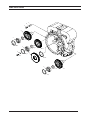
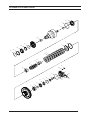
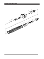
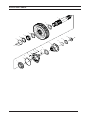
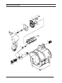
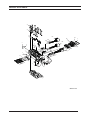
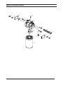
4.4.5.1 Calibration condition messages.............................................................................. 25
4.4.5.2 Calibration errors...................................................................................................... 25
4.4.6 PERFORMING A STALL TEST.......................................................................................... 26
5 Installation details....................................................................................................28
5.1 Converter drive coupling . ......................................................................................... 28
5.2 TRANSMISSION TO ENGINE INSTALLATION PROCEDURE............................................. 29
5.3 External plumbing............................................................................................................ 30
5.3.1 Cooler & filter lines specifications.................................................................................. 30
5.4 speed sensor installation............................................................................................. 31
6 Transmission Operation............................................................................................34
6.1 The transmission assembly............................................................................................ 34
6.1.1 The converter, pump drive section and pressure regulating valve.............................. 35
6.1.2 The input shaft and directional clutches........................................................................ 36
6.1.3 The range clutches .......................................................................................................... 37
6.1.4The output section............................................................................................................. 37
6.2 The transmission controls (refer to hydraulic diagram)............................ 38
6.3 Electric solenoid controls......................................................................................... 39
6.4 Powerflows, activated solenoids and hydraulic circuit.............................. 40
6.4.1 Neutral-1 Selected............................................................................................................. 40
6.4.2 Forward 1st speed............................................................................................................ 42
6.4.3 Forward 2nd speed........................................................................................................... 44
6.4.4 Forward 3rd speed............................................................................................................ 46
6.4.5 Forward 4TH speed........................................................................................................... 48
6.4.6 Reverse 1st speed............................................................................................................. 51
6.4.8 Reverse 3rd speed............................................................................................................ 54
6.4.9 Reverse 4TH speed........................................................................................................... 56
7 Troubleshooting guide.............................................................................................60
7.1 The Transmission................................................................................................................ 60
7.2 The input shaft and directional clutches............................................................. 60
7.2.1 Stall test............................................................................................................................. 60
7.2.2 Transmission pressure checks........................................................................................ 61
7.2.3 Mechanical and electrical checks.................................................................................... 61
7.2.4 Hydraulic checks............................................................................................................... 61
7.2.5 Controller (APC200): Please refer to functional description........................................ 61
7.3 TROUBLESHOOTING GUIDE................................................................................................... 62
7.3.1 Low clutch pressure........................................................................................................ 62
7.3.2 Low charging pump output flow..................................................................................... 62
7.3.3 Overheating..................................................................................................................... 62
7.3.4 Noisy converter............................................................................................................... 62
7.3.5 Lack of power.................................................................................................................. 62
7.4 CHECK POINTS....................................................................................................................... 63
7.5 SPEED SENSOR - STATIC STANDALONE TEST.................................................................... 67
7.6 Full flow valve components...................................................................................... 68
8 SECTIONAL VIEWS & PARTS IDENTIFICATION..............................................................69
TE27/32 4 SD
03/2010