1
Actuators
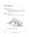
Installing the valve actuator drivers
Caution
Jun 2001
1130
2.
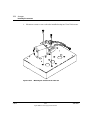
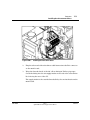
Loosen the actuator link arm lock screw at each actuator with a 3 mm
hex key wrench so that the coupling/shaft assembly is free to rotate. Push
the coupling shaft fully into the actuator.
3.
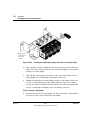
Turn the valve rotor index pin of each valve counterclockwise (CCW)
until it is 0.010-inch (0.25 mm) from the counterclockwise (left-hand)
valve stop.
4.
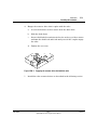
Reinstall the valve box top assembly.
5.
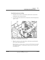
Gently rotate and push the coupling/shaft assembly with a blade-type
screwdriver until the slot on the coupling fully engages the valve rotor
index pin. Repeat this procedure for each valve installed.
Use care in performing the following operation so as not to accidentally turn
the valve rotor away from its preset (step 3) position.
6.
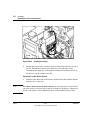
Make sure that all solenoid valves are turned “off” by the appropriate
valve controller. Turn on the air supply to the solenoid valve(s). The
piston rod of each actuator will move all the way out to the extended
(OFF) position. Very firmly tighten the link arm lock screw for each
actuator.
7.
Install the hardware for any variable restrictors present.
Valves
Agilent 6890 Gas Chromatograph Service Manual
11 of 12