1
AUTOMATIC PRODUCTS international, ltd.
MANUAL
MODEL 511
COLD BEVERAGE MERCHANDISER
SERVICE MANUAL
OPERATING SYSTEM
PARTS MANUAL
Please Do Not
Remove Manual
from Machine
75 West Plato Boulevard — St. Paul , Minnesota 55107-2095
RQ511 V3.0 05/06
Part # 57500001
Fast Track Links
Robo
Quencher
Dictionary
Installation
Programming
Parts
Troubleshooting
Express Warranty
Automatic Products international ltd. (APi) expressly warrants these automatic merchandisers (the "Unit"), manufactured by it,
to be free under normal use and service from defects in material or workmanship for a period of two (2) years from the date of
delivery of this Unit to the original purchaser. This warranty extends only to the original purchaser of the Unit. The exclusive
remedy for this warranty is limited to the repair or replacement, at APi's sole option, of any part or parts of the Unit that are
returned to APi or to the authorized dealer or distributor of APi from whom the unit was purchased with all transportation
charges prepaid, and which, on APi's examination, shall, conclusively appear to have been defective. This warranty does not:
a. extend to any Unit, or part thereof, that was subjected to misuse, neglect, or accident by other than APi after its
delivery to the original purchaser;
b. extend to any Unit, or part thereof, that was modified, altered, incorrectly wired or improperly installed by anyone
other than APi or used in violation of the instructions provided by APi;
c. extend to a Unit which has been repaired or altered by anyone other than APi or authorized dealer/distributor;
d. extend to a Unit which has had the serial number removed, defaced or otherwise altered;
e. extend to plastic or glass windows, lamps, fluorescent tubes and water contact parts;
f. extend to any unit used outdoors
g. extend to accessories used with the Unit that were manufactured by some person or entity other than APi.
APi DISCLAIMS ALL OTHER WARRANTIES OF ANY KIND AS TO THE UNIT AND ALL WARRANTIES OF ANY KIND AS
TO ANY ACCESSORIES. THIS DISCLAIMER OF WARRANTIES INCLUDES ANY EXPRESS WARRANTIES OTHER
THAN THE LIMITED WARRANTY PROVIDED ABOVE AS TO THE UNIT AND ALL IMPLIED WARRANTIES OF
MERCHANTABILITY AND FITNESS FOR A PARTICULAR PURPOSE AS TO THE UNIT AND ANY ACCESSORIES.
UNDER NO CIRCUMSTANCES SHALL APi BE RESPONSIBLE FOR ANY INCIDENTAL, CONSEQUENTIAL OR
SPECIAL DAMAGES, LOSSES OR EXPENSES ARISING FROM OR IN CONNECTION WITH THE USE OF, OR THE
INABILITY TO USE, THE GOODS FOR ANY PURPOSE WHATSOEVER. No representative of APi or any other person is
authorized to assume for APi, or agree to on the behalf of APi, any other liability or warranty in connection with the sale of this
Unit.
APi reserves the right to make any changes or improvements in its products without notice and without obligation and without
being required to make corresponding changes or improvements in Unit theretofore manufactured or sold.
To achieve the most trouble-free operation from your AP511 Cold Beverage Merchandiser, it is recommended that
this service manual be thoroughly read and the instructions followed pertaining to installation, servicing and
maintaining of the unit.
Should you have questions pertaining to this manual or the vendor, please contact your APi distributor or write
directly to:
Automatic Products int. ltd.
75 West Plato Blvd.
St. Paul, MN. 55107 USA
651-224-4391
651-602-3558 (fax)
© 2003 Automatic Products international, ltd
BACK
2
INTRODUCTION
The Automatic Products 511 Beverage Merchandiser is the state of the art in vending technology. The 511 features a
robotic delivery system with current limiting motors. The AP 511 introduces a unique delivery mechanism that
eliminates the agitation of a carbonated beverage that is usually experienced with the delivery of these products from
other machines. The design of the product storage shelves permits the use of a wide variety of packaging, ranging
from a standard 12 ounce can to most 20 ounce plastic and glass bottles available in the beverage marketplace
today. The easy to understand, numerical key pad selection panel provides access to all setup and diagnostic service
modes. All selections can be individually priced with the use of an Multi-Drop Buss (MDB) type coin mechanism and
bill validator.
HOW TO USE THIS MANUAL
This manual is divided into four basic parts:
1. Unpacking and Installation.
2. Optional Equipment & Refrigeration
3. Components and Refrigeration.
4. Operating System.
5. Programming
6. Troubleshooting
7. Parts
WATCH THROUGHOUT THE MANUAL FOR THIS SPECIAL
♦ DIAMOND MARK. THIS INDICATES A POINT OF
SPECIAL INFORMATION OR A HINT THAT WILL ASSIST
YOU IN SETTING UP,OPERATING OR
TROUBLESHOOTING THE MACHINE.
CAUTION: Certain procedures in both the operating section and the service
section require that voltage be on in the machine. Only trained personnel should
perform this function. Exercise extreme caution while performing these
procedures. These procedures will be marked with the lightening bolt symbol as it
appears at left.
CAUTION: Certain procedures in both the operating section and the service
section requires a qualified trained technician to perform the particular task at
hand. These procedures will be marked with the exclamation symbol as it appears
at left.
CAUTION: It is important that this machine is hooked up to the proper voltage and
polarity for your country. Use a Voltmeter to verify voltage and polarity. Should the
reading be any different than a normal reading for your country or if you are unsure of
what the reading should be contact an electrician.
CAUTION: Different Countries may have unique plug arrangements. Ensure that the
machine is properly grounded before operating.
CAUTION: For 230Vac applications, the power cord in this machine is of a type Y
attachment. If the power cord is damaged, it must be replaced by: the manufacturer, it’s
service agent, or a similarly qualified person, in order to avoid a hazard.
RQ511 V3.0 05/06
3
BACK
3
FEATURES OF THE APi 511 BEVERAGE MERCHANDISER
STANDARD FEATURES
•
•
•
•
•
•
Electrical
Capacity up to 320 beverages
Maximum of 40 different selections
Multi Drop Bus capabilities
Fault Diagnostics
First in first out shelf loading
Health control for vending dairy products
Individual pricing by selection
Free Vend Feature
Software contained Accountability:
vend counter, cash total
IMPORTANT! Only the MDB coin mechanisms
and bill validators listed on page 6 should be used in
this machine.
DISPLAY
•
•
•
•
•
•
COIN MECHANISMS
IMPORTANT! DO NOT PLUG COIN
MECHANISM INTO THE CONTROL BOARD WITH
POWER ON. THIS MAY RESULT IN DAMAGE OF
THE COIN MECHANISM AND LOGIC CONTROL
BOARD.
PRICING
•
•
•
•
A grounded electrical outlet rated at 120 volts 15 amp
must be available within six feet of the vendor.
User friendly four character, seven segment display
to help with the selection process and provide
customer feedback
LED segments to indicate:
Credit
Selection price
Remove product
Diagnostic messages
SPECIFICATIONS
Ratings:
ACCEPTABLE
AMBIENT
OPERATING
TEMPERATURE RANGE
All equipment manufactured by Automatic Products Int.
Ltd. Is designed to operate in a temperature range of
10° C to 38° C (50° F to 100° F)In still air (75% R.H.
non-condensing). The machine is capable of being
stored in a temperature range of –18°C to 68°C (0°f to
155°F).
120v, 60 hz, 11amps, 1320watts
230v, 50hz, 5amps, 1150watts
6”
It is necessary on Robo machines to
have 3” clearance on the left side of
the machine for the door to extend 3”
past the cabinet side. This machine
requires 6” clearance behind and
above the machine for air circulation.
Noise Level:
Operates at less than 70dba (A)
Sound pressure levels measured
Per ISO 11201:1995
3”
Dimensions:
Height: 72 inches (1830mm)
Depth: 34-1/8 inches (864mm)
Width: 44-3/8 inches (1130mm)
Shipping wt. 922 lbs.
REFRIGERATION
Compressor
- 1/2 Horse Power
Refrigerant
- R134A
Charge - 13.0 oz. (.37 kg.)
Design Pressures:
High side-200 psi
Lowside-135psi
RQ511 V3.0 05/06
4
BACK
4
Robo Quechertm Dictionary
tm
As production of the Robo Quencher continues to increase, and
more operators become familiar with the robotic delivery assembly
used in the machine, we need to define some of the terms coming
into common use when working with or talking about Robo
tm
Quencher . Here is a glossary of those terms:
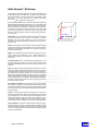
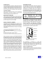
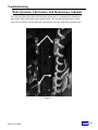
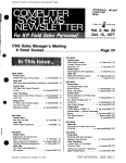
X, Y, and Z Axis -Based on the coordinate system first defined by
Rene Descartes almost 500 years ago, the X, Y, Z coordinates help
tm
define the direction the Auto Glide assembly moves to select and
deliver the customer's beverage. The X direction is left and right, the
Y direction is up and down, and the Z direction is in and out, or front
to back. The majority of the mechanical components in the Robo
tm
Quencher derive their name from the function it performs during the
vend sequence.
tm
Initialization -This is the process that the Auto Glide assembly
goes through whenever the machine is powered up with this
assembly not in its Home position, or if the vend process is
interrupted. Successful completion of Initialization can be used as a
diagnostic tool.
Y direction
Z direction
X direction
XY Bar -The XY Bar is the five-foot long vertically mounted bar that
moves across the front of the selections when a customer makes a
selection. This bar contains the X Motor, the Y position Home Switch
and the Cage assembly.
X Motor -The X Motor moves the XY Bar left and right to the proper
column during the vend sequence. The X motor determines its
position with an optical sensor passing over a series of slots in the X
Timing Bar.
Y Position Switch -The Y Position switch is located about 1/3 up
from the bottom of the XY Bar. As the Auto Glidetm assembly goes
through the Initialization process, this switch provides a fixed point of
reference.
Cage -The Cage (or shuttle) is the rectangular assembly mounted on
XY Bar that collects the beverage and delivers it to the home position.
The Cage assembly contains the Y Motor in the top of the assembly,
the Z Motor and it's position switches in the base of the Cage, and
Golden Eye detection assembly to ensure a product is delivered
every vend. The floor of the Cage is known as the Shoe, and provides
a stable ridged platform onto which the selected beverage slides into
the Cage. The Shoe also contains an alignment mark for use during
an XY Alignment Procedure.
XY Alignment Procedure -This procedure should be performed
every time the machine is moved. After the machine has been leveled
front to back and side to side, this procedure confirms that the XY Bar
is plumb to the shelves by checking the Cage alignment with the four
corner selections.
Z Motor -The Z Motor is located in the bottom of the Cage and
pushes the bottom of the Cage towards the Escapement on the end
of a beverage shelf. This motion opens the Escapement, which
allows the beverage to slide into the cage. The Z Motor's action is
controlled by two micro-switches, which when actuated by a gear
track, identify whether the Cage is in a normal or extended position.
Cage Lock Motor -This motor is located directly below the Cage in
its home position. The Cage Lock Motor rotates to extend a locking
bar into the base of the Cage to prevent the Cage from being moved
from its home position when the Delivery Door is opened to permit
removal of the beverage.
RQ511 V3.0 05/06
5
BACK
5
APi 511 UNPACKING AND INSTALLATION
The 511 Robo Quencher™ Beverage Merchandiser is assembled and packed so that a minimum amount of time is
necessary for preparation to install it on location. The following steps are recommended to insure correct unpacking.
UNPACKING
CLEANING
1. Shipping Damage: Thoroughly inspect the exterior of
the carton for damage which may have occurred during
shipment. Report any damage to delivery carrier and
follow their instructions.
The 511 Robo Quencher™ will do the best product
merchandising job for you if it is kept clean. The display
window can be cleaned with any good glass cleaner. The
exterior and interior surfaces should be cleaned with
warm water and mild detergent. Rinse thoroughly and dry
all surfaces.
2. Remove shipping carton, plastic bag from vendor and
remainder of packing material. Inspect exterior of cabinet
for damage.
SAVE SHIPPING CARTON FOR
MACHINE IS TO BE RESHIPPED.
REUSE
CAUTION: Do not use any cleaners containing silicon as
this could cause electrical failures.
IF
3. Removing Vendor with a Fork Lift Truck:
From the side of the vendor tip the vendor backward and
run forks under the cabinet.
The main product shelves can be best cleaned with the
product slides removed from the machine. The slides can
easily be removed by pushing the slide back and lifting up
and out on the front of the slide.
4. Remove clip from lock handle and open front door. If
machine is equipped with a lock, the keys will be in the
coin return cup. Inspect cabinet interior for evidence of
damage.
The product slides can be cleaned with hot soapy water,
and should be dried thoroughly before returning them to
the product shelves. DO NOT USE ANY ABRASIVE
MATERIALS ON THE PRODUCT SLIDES. Abrasive
materials will damage the finished surface of the slides.
NOTE: Because the weight concentration is toward
the back of the cabinet, trucking and lifting should be
done from the back. CAUTION should be taken when
trucking from side.
Clean the acceptor on the coin mechanism frequently as
accumulated dirt in this area can cause coins to hang or
not be accepted. Follow recommended cleaning
procedures as described by the manufacturer.
5. On machines with lock in place, unlock and turn handle
to open door. When no lock is furnished, remove clip and
turn handle. Swing door to its full open position. Remove
all packing tape and paper from various areas of
machine.
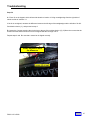
The delivery cage and sensor assembly should be
cleaned with a damp cloth during each service visit.
Wiping down the delivery cage assembly will prevent any
syrup or dirt build up interfering with proper operation of
the unit or the optical sensors. Wiping down the product
delivery cage sensor will also prevent malfunctions from
occurring.
6. Warranty. The warranty card is shipped in the service
envelope. It must be filled out in full and mailed at once
to insure coverage.
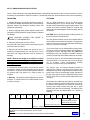
E
5
1
Ï
1
0
1
Ï
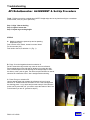
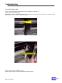
The delivery door assembly can easily be removed from
the door for cleaning. Once the bottle shield is removed,
the delivery door assembly can easily be removed by
removing two Phillip screws along the top of guide
bracket below the coin slot assembly. The delivery door
assembly can then be disassembled on a bench for
cleaning.
3
6
Ï
5
0
0
1
Ï
Sequential build number
Starts at 001 every day.
Numerical day of the year – Jan 1st = 001, Dec 31 = 365.
Year 01 – Last two digits of the year.
First digits indicates model, example shown is a 511 (Beverage Merchandiser) – The machine identification may
contain up to six characters dependent upon the model.
Suffixes
BACK
V3.0a05/06
6 export outside of North America.
E RQ511
– Indicates
machine built specifically for
6
INSTALLATION
Leveling the machine:
Leveling the machine once it has been delivered to a
location is critical for the proper function of the machine.
The four leveling screws in the legs are the means of
leveling the machine. After positioning the machine, level
machine in front to rear and right to left directions
INSTALL AIR DEFLECTOR
Install air deflector on rear screen outlet by loosening the
mounting screws and placing the keyholes over the screw
heads, and tightening the screws.
CAUTION: THIS
MACHINE IS
DESIGNED FOR INDOOR USAGE
ONLY. ANY OTHER USAGE MAY
VOID
THE
MANUFACTURERS
WARRANTY.
CAUTION: THE FOLLOWING
PROCEDURE REQUIRES THAT THE
MACHINE HAVE POWER APPLIED
AND A POTENTIAL ELECTRICAL
SHOCK HAZARD EXISTS.
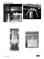
Voltage and Polarity Check:
It is important that this machine is hooked up to the
proper voltage and polarity. Using a voltmeter, perform
the following checks from the illustration below.
117 VAC
117 VAC
Less Than
1 VAC
Note: should the readings be different from
above, have a certified electrician correct the problem.
CAUTION: Certain procedures may
cause moving parts to operate & the
potential for injury may exist. Exercise
caution when power is applied as
parts may move without warning.
Coin Mechanism Installation:
With the monetary door fully open, locate the control
board mounted to upper left side of the inner door. Locate
the mode switch on the control board and press the mode
switch one time and press 11. The XY mechanism lock
will release and move left to a standby position. Turn
main power switch off and swing the coin mech cover to
the left to install the coin mechanism. Install the coin
mechanism hold down screw provided. Plug coin
mechanism into six pin MDB plug provided.
Dollar Bill Validator Installation:
Locate the control board on the monetary door. Below the
control board will be a filler plate held in place with four
nuts. Remove the filler plate and install dollar bill validator
in place using the same hardware. Connect the Acceptor
harness into the six pin MDB harness routed from the
coin mechanism. Plug the other six pin MDB connector
from the validator harness onto the P2 pin out connector
on the control board.
LOADING PRODUCT SHELVES:
Open the right and left doors to full open position. Lift the
red shelf locking lever to release the shelf. Place the first
three bottles into position desired, slightly push the
product bottles back and insert the next product bottle.
Follow the same procedure for loading the remainder of
the machine.
SET SELECTION PRICE:
Price settings are done individually. Maximum price
capability is $99.95. For price setting instructions refer to
Quick Set-Up Reference Sheet.
Install selection price tabs:
Price tabs are included in all manual packets. Price tabs
are to be installed onto the dispensing gate above the
item selection label.
SET / CHECK TEMPERATURE:
The cabinet temperature is settable from +32° to +50°
Fahrenheit (0°c-+10°c) inclusive in 1 degree increments.
For temperature setting instructions refer to Quick Set-Up
Reference Sheet. Factory default temperature setting is
35°F
Cabinet temperature can be checked by depressing and
holding the (<) or (>) arrow key on selector key pad for
three seconds. The temperature of the cabinet will then
appear on the display as follows: the (>) arrow key will
display Fahrenheit / the (<) arrow key will display
Celsius.
Z MECH HEIGHT ADJUSTMENT:
After loading all product into machine, test each selection
for proper dispensing into the Z mech. If product is not
dispensing correctly into Z mech (i.e.- tilting forward)
adjust the height of the Z mech so that the lower edge is
1 click (button press) below the slide. For Z mech height
adjustment, please refer to Quick Set-Up Reference
Sheet.
BACK
RQ511 V3.0 05/06
7
7
POWER SUPPLY:
The 120 VAC power cord from the wall outlet enters the
rear of the machine and plugs into the main junction box
located in the upper right side the cabinet above the coin
mechanism. The voltage output to the board is 24 volts
and is connected to the P3 position of the control board.
LIGHTING SYSTEM:
There is only one florescent lamp in the 511 Beverage
Merchandiser. The lamp is located in the top of the
cabinet and lights up the main product area.
MAIN PRODUCT SHELVES:
There are five rows of eight columns. Each selection has
a dual dispensing gate mounted to the front of the shelf.
All columned shelves are identical and interchangeable.
The paired columned shelves are supported vertically to
prevent warping due to product weight.
PRODUCT DELIVERY ASSEMBLY:
The delivery door is located below the T-handle on the
monetary door. The Z mechanism is located in the main
cabinet. In standby, the Z mechanism is positioned and
locked in place directly in front of the coin mechanism.
The product delivery assembly consists of five primary
components:
1) X mech moves the delivery assembly left to right.
2) Y mech moves up and down.
3) Z mech moves in and out engaging the dispensing
gate.
4) Product Delivery Door (Home Position)
5) Lock motor locks Z mech while bottle is in the Z mech.
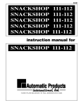
REFRIGERATION UNIT
The refrigeration unit is located in the bottom right side of
the main cabinet. The air inlet for the compressor is
located on the bottom left side of the cabinet and is
protected by a removable screen. An air deflector is
included with each machine and should be installed on
the mounting screws on the rear of the machine. The
purpose of the air deflector is to ensure proper air flow
and correct heat transfer, and to prevent the machine
from being pushed up against the wall.
IMPORTANT: THE
AIR
INLET
SCREEN SHOULD BE CHECKED AND
CLEANED EACH VISIT!
The evaporator is mounted above the compressor
assembly, and when installed, is entirely within the
insulated cabinet. The single evaporator fan is mounted
above the evaporator. The chilled air is circulated up
through a large duct on the right side of the cabinet,
forced out over the top of the product shelves area and is
then drawn down to the inlet of the evaporator and is
pulled through the evaporator by the one fan.
Chilled Air Flow
Evaporator Fans
Evaporator
Compressor
When a selection is made, the control board insures that
the delivery door is closed, the Z mechanism is empty. If
all systems are ready, the cage lock is released, the X
axis motor locates vertical column using a optical sensor
and the Y axis motor (locates shelf position using an
optical encoder) hovers to selected item. The Z Mech
motor is activated engaging the dispensing gate and
stops when the Z mech out switch is made. When the
dispensing gate is engaged the product will slide into the
Z mech. The Z mech will wait one second to confirm a
product has been dispensed or until the sensor is
blocked. If a product is not present in the Z mech, the Z
mech will return home and display sold-out. If a product is
present, the Z mech will run until the Z in switch is
activated. Once this occurs, the Z mech will return to the
home position and lock in place. The delivery door then
opens, and remains open until the product is removed.
Inlet Air Flow
Re frigera tion Air Flo w and Primary
Re frigera tion Com ponen ts
The temperature is controlled by a solid state
temperature sensing device, located on the right panel of
the cabinet and is connected to the control board. The
control board then activates a low voltage relay that
controls the operation of the compressor.
INSTALL AIR DEFLECTOR:
Install air deflector on rear screen outlet by loosening the
mounting screws and placing the keyholes over the screw
heads and tightening the screws.
BACK
RQ511 V3.0 05/06
8
8
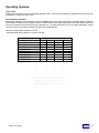
Operating Systems
Control Board & Display
The control board contains all of the decision-making
control and the display. All peripherals plug into the
control board. The display on the control board indicates:
Credit, Price of the Product, Diagnostic Information and
Options (In Service Mode). In addition, there are (2)
LED's that indicate Make Another Selection and Use
Correct Change
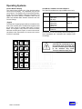
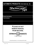
Keypad
The Selection keypad (pictured below) is located on the
front of the monetary door The Selection Keypad is used
as an input source for settable data when in Service
Mode. The keypad is only active for service functions
when the monetary door is open, so even in the event of
vandalism to the control bezel; no access to the service
functions is permitted.
1
2
3
4
5
6
7
8
9
*
<
0
C
Coin Mechs, Validators and Card Readers:
The Robo Series Machines support MDB protocol only.
Mars
CoinCo
Conlux
MDB Coin Mechanism
MDB Bill Validator
TRC-6510
TRC-6512
VN-4510
9302-GX,
USQ-G701
USQ-G703
USQ-L701
USLZ-004-01F
CCM 5 G
VN2502-U5M
VN2512-U5M
MAG 32
MAG 52
USLZ-004-01F
The Robo Series will automatically determine at power up
which peripherals are connected and configure itself
accordingly.
CAUTION: Do not attempt to move
the machine while it is loaded with
product. Possible injury or damage
to the machine may occur.
Transport machine empty only!
#
>
BACK
RQ511 V3.0 05/06
9
9
Operating Systems
INTRODUCTION
The APi 511 Beverage Merchandiser is user friendly and allows the user to move freely through the programming by choosing
selected keys. It provides ease for insertion, modification, and deletion of operational parameters and data. In addition, the
program system provides the user with status and diagnostic messages to aid in the use and service of the machine.
OPERATIONAL MODE
The operational mode provides the machine with the ability to vend products. The machine is in Operational Mode whenever
the monetary door of the machine is closed. Upon opening the monetary door, the machine will remain in Operational Mode
until the Mode Switch on the Control board is depressed at which time it will enter the Service Mode.
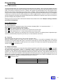
SERVICE MODE
The Service mode is entered by depressing and releasing the Mode Switch, on the Control Board. A second depression of the
Mode Switch will exit the Service Mode and return the Control Board to the Operate Mode. Entrance into the Service mode will
clear any current credit and disables all credit acceptance. In addition, entering the Service Mode, displays diagnostics
information until an additional Service Mode function has been selected. Diagnostics information includes MDB errors and
defective or jammed arm movement motor codes. If there are no errors are present “nOnE” will be displayed. If errors are
present “n x” will be displayed where x is the number of errors. Errors may be viewed by using the arrow keys showing the
most recent error first, or you may skip viewing errors by pressing other service keys. When you have viewed all the errors or
you press the # key, “CLrn” will appear to allow you to clear the errors. The # key may then be used to toggle between ‘y’ and
‘n’. To exit the C key must be pressed. The ‘y’ or ‘n’ choice is only made if you exit with the C key (not the mode key).
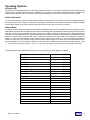
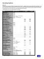
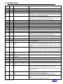
The following table lists the Multi-Drop Bus errors that may be displayed in the Diagnostics Mode:
RQ511 V3.0 05/06
Multi-Drop Bus Error
Display
Invalid changer scale factor
“CscF”
Defective coin tube sensor
“tSnS”
Coin jam detected
“CJAM”
Coin tube jam detected
“tJAM”
Coin acceptance problem detected
“CnEr”
Acceptor unplugged
“AcEr”
Coin changer ROM checksum bad
“ChEr”
Invalid acceptor scale factor
“bScF”
Defective bill sensor
“bSnS”
Bill jam detected
“bJAM”
Bill stacker is full
“StFL”
Bill cash box is out of position
“Cshb”
Bad bill motor detected
“bMtr”
Bill acceptor ROM checksum bad
“bLEr”
Invalid card reader scale factor
“rScF”
Card error detected
“CdEr”
Invalid card detected
“bCrd”
Card reader jam detected
“rJAM”
Communications error detected
“CoEr”
Card reader failure
“brdr”
10
BACK
10
Operating Systems
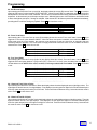
Power Up State
Following a power-up or reset condition, the display will show “----“and then credit available will show on the display
INSERT MONEY AND
RECEIVE CHANGE BELOW
.00
CREDIT
MAKE ANOTHER SELECTION
USE CORRECT CHANGE
Operate Mode
Upon closing the door, the display will show the firmware
revision level and then enter operational mode.
Standby
In stand by, zeros will be shown along with the designated
decimal point. Accumulated credit will be shown until a
selection is made. Position of the decimal point is determined
by the MDB peripherals.
Keypad echo
When the first numeric key is pressed the display will show the
selection number in the second leftmost digit. This character
will remain for 5 seconds or until another key is pressed. If a
second numeric key is entered, the pair will be shown on the
display for one second and then the associated price for the
product will display. If the selection is disabled the display will
show “d”. and flashes the " Make Another Selection " LED.
Credit Accumulation
Credit may be accumulated through a coin mechanism, bill acceptor or card reader. Card reader credit cannot be mixed with
coin and/or bill credit during a single transaction or vend. Credit acceptance will be disabled when the accumulated credit
equals or exceeds the highest priced item. Credit accumulation from any source is disabled or escrowed if change is not
available. If the amount of card reader credit available exceeds the maximum displayable credit, the maximum credit will be
displayed.
Vend process
After a keypad entry is made the control board determines if sufficient credit is available for the selection attempted. If the credit
is greater than or equal to the selection price, a vend attempt will be made for that selection. During this time, the selection will
be shown on the display. If credit is less than the selection price, the price will be displayed and the Use Correct Change LED
will flash for 5 seconds or until a new selection key is pressed.
Change payment
Change will be returned after the vend is complete. The amount of change to be returned will be displayed until all coinage is
paid back. The least amount of coins available will be paid back for all credit returns.
Use Correct Change LED
If the level of the changer's least value coin tube is below the lowest sensor, the "Use Correct Change" LED will be illuminated
continuously. If the machine is unable to vend the selected item because of low change, the "Use Correct Change" LED will
flash 5 times.
Make Another Selection LED
If the machine is unable to vend the selected item, the “Make Another Selection “LED will be flash 5 times.
In the case of a sold out condition the LED will flash and the display will read “SOLD OUT” for 30 seconds or until a keypress.
RQ511 V3.0 05/06
11
BACK
11
Operating Systems
Token Vends
Following the acceptance of a token, the display will show "FrEE". Further credit acceptance is disabled and a single item may
be selected to vend for the token credit.
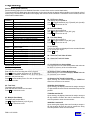
Accountability Information
All MIS data is stored as both resettable and non-resettable with the exception of Machine Identification Number, Machine
Serial Number, Software Version Number, Number of MIS Resets, Number of Machine Resets, Door Open History, and Value
of Coins in Tubes which shall be stored as non-resettable only. All vend counters will roll over at 7 digits (9,999,999). All cash
counters will roll over at 8 digits including the decimal point (999,999.99).
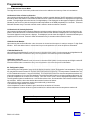
Vend accounting (MIS) is updated as follows:
* Indicates which field is updated for a given vend type.
Vend Type
Field
Token Vend
Testvend
#VENDS
*
*
$VENDS (Sale Price)
*
#/PROD
*
*
$/PROD (Sale Price)
*
#/TESTVEND
*
# /FREE
$ /FREE
# /TOKEN
*
$ /TOKEN
*
Table 1: MIS Field Update Chart
RQ511 V3.0 05/06
12
Freevend
*
*
*
*
BACK
12
Operating Systems
DEX/UCS
The Robo Series supports DEX/UCS Communications Protocol - NAMA Vending Industry Data Retrieval Standard. The
machine will automatically recognize the DEX/UCS device when it is plugged into the control board and will recognize when the
device initiates the communication protocol. The transmission/reception of data to the device will then take place automatically.
The MIS data stored by the machine for a DEX/UCS download is as follows:
The MIS data stored by the machine shall be as follows:
NAME
DEX HEADER FIELD
MACHINE SERIAL #
MACHINE ID #
MACHINE VERSION #
MACHINE LOCATION
MACHINE ASSET #
CONTROL BOARD SERIAL #
CONTROL BOARD ID #
CONTROL BOARD SW VERSION #
DECIMAL POINT POSITION
TOTAL VALUE OF SALES
# OF VENDS
# OF TEST VENDS
# FREE VENDS
VALUE FREE VENDS
BILL VALIDATOR SERIAL #
BILL VALIDATOR ID #
BILL VALIDATOR SW VERSION #
COIN CHANGER SERIAL #
COIN CHANGER ID #
COIN CHANGER SW VERSION #
VALUE OF CASH SALE
# OF CASH SALES
VALUE OF BILLS STK'D
VALUE OF CASH IN
VALUE OF COINS TO TUBES
VALUE OF COINS ROUTED
TO THE CASH BOX
VALUE OF CASH DISPENSED
VALUE OF CASH MANUALLY
DISPENSED
VALUE OF EXACT CHANGE VENDS
TUBE FILL VALUE
CURRENT VALUE OF COINS IN
TUBES
# OF TOKEN VENDS
VALUE OF TOKEN VENDS
CASHLESS SERIAL #
CASHLESS ID #
CASHLESS SW VERSION #
# OF CASHLESS VENDS
VALUE OF CASHLESS VENDS
LOOP HEADER
VALUE OF VENDS
BY SELECTION NUMBER
ID101
ID102
ID103
ID104
ID106
CB101 = “API” + 17 DIGIT SERIAL #
CB102 = “ROBO”
CB103 = LATEST REVISION
ID401
# OF VENDS
BY SELECTION NUMBER
# OF FREE VENDS
BY SELECTION NUMBER
LOOP TRAILER
# OF READS WITH RESET
# OF READS
# OF MIS RESETS
# OF DOOR OPENS
# OF HEALTH SHUT DOWNS
# OF INITIALIZATIONS
# OF X MOTOR FAILURES
# OF Y MOTOR FAILURES
# OF Z MOTOR FAILURES
RQ511 V3.0 05/06
HISTORICAL
FIELD
RESETABLE
FIELD
VA101
VA102
VA202
VA302
VA301
VA103
VA104
VA204
VA304
VA303
CA201
CA202
CA308
CA305
CA307
CA306
CA203
CA204
CA304
CA301
CA303
CA302
CA403
CA404
CA401
CA402
CA902
CA1002
CA1501
CA901
CA1001
TA202
TA201
TA204
TA203
DA202
DA201
DA204
DA203
PA202
PA204
PA201
PA203
BA101
BA102
BA103
CA101
CA102
CA103
DA101
DA102
DA103
LS101 = (0001)
PA101 = (SELECTION #)
(# = 10 TO 40)
PA102 = PRICE
PA401
LE101 = (0001)
EA301
EA309
EA3010
EA201 = “EGS”
EA205 = CURRENT STATUS
1 = DOOR CURRENTLY OPEN
EA201 = “EJH”
EA201 = “ECU”
EA201 = “EJL01”
EA201 = “EJL02”
EA201 = “EJL03”
13
EA203
EA202
EA203
EA203
EA203
EA203
EA203
EA202
EA202
EA202
EA202
EA202
BACK 13
Programming
Service Modes (quick reference)
See the following pages for more detailed information on each of the service modes listed below.
To access the Service Mode press the mode button on the control board, the display will prompt Sr or scroll through a list of
errors (if any). The last error will remain on the display until a Service mode is entered. To access the service modes, enter one
of the mode numbers below.
MODE
NUMBER
01
02
03
04
05
06
08
09
11
12
13
15300
Price Assignment
Test Vend
Multiple Vend Setup
Bill Escrow Setup
Force Vend Setup
Free Vend Setup
Historical Total Value of Sales
Historical Total # of Vends
Coin Mechanism Access Mode
Historical Value of Sales By Selection
Historical # of Vends By Selection
Allows setting a 17 # character serial number
17200
18400
20
21
22
24
Allows setting 17 numeric character Machine
Asset number.
Allows setting 17 numeric character location ID
Refrigeration Setup
Health Timer Setup
Machine Setup And Tests
Tube Fill Mode
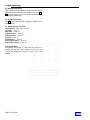
04 - Bill Escrow Setup
The display will prompt ESc n.
Use # to toggle between n (no), F (first bill) or L (last bill).
Press C or close door to exit.
05-Force Vend Setup
The display will prompt Fu n.
Use # to toggle between n (no) & Y (yes).
Press C or close door to exit.
06 - Free Vend Setup
The display will prompt Fr n.
Use # to toggle between n (no) & Y (yes).
Press C or close door to exit
Accountability
The first four digits are displayed for two seconds followed
by the second four digits.
Press C to exit.
08 - Historical Total Value of Sales.
09 - Historical Total # of Vends.
Service Mode Numbers
01 - Price Assignment
The display will prompt Prc.
Enter the price to be set using the numeric keypad.
Press # and the display will prompt “S” for Selection.
Enter all the selection numbers to be set at the price
entered in the previous step.
Press # to enter another price or C to lock in and go back
to the service mode.
02 - Test Vend
The display will prompt SL.
Enter the selection numbers to be tested.
Press C or close door to exit.
03 - Multiple Vend Setup
The display will prompt nuL n.
Use # to toggle between n (no) & Y (yes).
Press C or close door to exit.
RQ511 V3.0 05/06
11-Coin Mechanism Access Mode
The cage will move out of the home position and coins can
be added to inventory of the coin mechanism.
12-Historical Value of Sales By Selection
Upon entering, the control board displays”HVSS”and waits
for a selection to be entered.
13-Historical # of Vends by Selection
Upon entering, the control board displays “HNSS”and
waits for a selection to be entered.
15300-Set Serial Number
Upon entering, the display clears and is ready to accept a
17 digit serial #.Once the code is entered the # key must be
pushed.
17200-Set machine ID
Upon entering, the display clears and is ready to accept a
20 digit machine ID.Once the code is entered the # key
must be pushed to enter the new number.
18400-Set Location ID
Upon entering the display clears and is ready to accept a
20 digit location ID.Once the code is entered the # key
must be pushed to enter the new number.
BACK
14
Programming
20 - Refrigeration Setup
Upon entering the “Refrigeration” setup mode the display
shows the current “Refrigeration” temperature. The < or
> key may then be used to increase or decrease the
temperature respectively.
21 - Health Timer Setup
The # key may then be used to toggle the “Health Timer”
option ON/Off.
22 - Machine Setup and Tests
Vend Position: “Row” then “Column”
Go Home: “*” then “1”
Safe Area: “*” then “4”
Z Mech Extend: “*” then “7”
Z Mech Retract: “*” then “8”
Set Row: “*” then “3”
Set Selection: “*” then “9”
Product Door Open: “*” then “5”
Product Door Close: “*” then “6”
24-Tube Fill Mode
The display will prompt” tF--“and waits for coins to be
inserted into the top of the changer. As the coins are
inserted the display will show the value of the coins
entered.
RQ511 V3.0 05/06
BACK
15
Programming
Service Mode (detailed)
The Service Modes allow you to update all the prices and options in the machine. Upon opening the machine door and
depressing the Service button located on the bottom left corner of the control board, the control board enters the Service
mode. If a period of no activity occurs for 5 minutes, the controller will automatically revert to the Operate mode.
Entrance to the Service mode clears any current credit. In addition, entering the Service mode, will display the # of
errors, each error may be scrolled through using the arrow keys. When you have viewed all the errors,”CLrn” will appear
to allow you to clear the errors.The # key may then be used to toggle between y and n.To exit the C key must be
pressed. Diagnostics information includes Multi-Drop Bus errors and defective or jammed motor codes. If no errors are
present the display will prompt Sr for service.
Entering one of the service mode numbers below allows access to that service mode. Example: entering 01 will take
you into price assignment.
Service Mode Numbers
01 - Price Assignment
Upon entering the price assignment mode 01 the controller will display "Prc " for 2 seconds and then “ . ”.
Enter the price to be set using the numeric keypad.
Press # and the display will prompt “S” for Selection.
Enter all the selection numbers to be set at the price entered in the previous step.
Press # to enter another price or C to lock in and go back to the service mode.
The maximum price is that can be set at $99.99 due to the display limitations. (The display format is dependent upon
scale factor and decimal point position provided by the credit peripherals connected.)
02 - Test Vend
Upon entering the Test Vend mode 02, the controller will display "SL ".
Enter the selection number to be tested. Once the selection is entered, a vend will be attempted. If the vend is
successful, the controller display "SL" again. If the selected motor fails, the controller will display "FAiL" for 2 seconds
and then display “SL” and wait for another selection to be entered. Test Vend will be turned off automatically on door
closure. Press C or close door to exit.
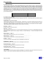
03 - Multiple Vend Setup
Upon entering the “multi–vend” set up mode 03, the display shows the current “Multi-vend” state. Use # key to toggle
the “Multi-vend” option between “nul n”, n = disabled or “nul Y” = enabled. Multi-vend enabled (nul Y) allows the
customer to make additional selections as long as sufficient credit exists to purchase the lowest priced item in the
machine. The customer may establish additional credit at any time when in this mode. If the customer presses the Coin
Return Lever, the amount of available credit drops below the lowest priced item in the machine (by set price) or a 30
second time-out expires, change is returned regardless of the state of Multiple Vend. Multi-vend disabled (“nul n”) will
cause the change to be paid back immediately after product is removed.
Press C or close door to exit.
Multi-Vend State
Multi-vend enabled
Multi-vend disabled
RQ511 V3.0 05/06
Display
"MULy"
"MULn"
BACK
16
Programming
04 - Bill Escrow Setup
Upon entering the “Bill escrow” set up mode 04, the display shows the current “Bill escrow” state. The # key is used to
toggle the “Bill escrow” option between FIRST/LAST/OFF. When Escrow FIRST is enabled the unit shall hold the first
bill deposited in escrow until a vend is initiated. Once a vend is initiated the bill must be stacked before the product is
dispensed. In this mode only one bill maybe used per vend. With this feature set to LAST all bills are stacked until credit
is above the highest vend price, if change is available. With escrow OFF all bills accepted will be stacked immediately,
providing there is sufficient change to payback. Press C or close door to exit.
Bill Escrow State
Bill escrow first
Bill escrow last
Bill escrow disabled
Display
“EScF”
“EScL”
“EScn”
05 - Force Vend Setup
Upon entering the “Force vend” set up mode 05 the display shows the current “Force vend” state. Use the # key to
toggle the “Force vend” option between ON/OFF. When the force vend option is enabled, once credit has reached the
lowest vend price set in the machine, the customer must purchase at least one item prior to requesting that any
remaining credit be returned. Force Vend does not apply when debit cards are used or if all coins/bills are held in
tubes/escrow. Press C or close door to exit.
Force Vend State
Force vend enabled
Force vend disabled
Display
“Fu Y”
“Fu n”
06 - Free Vend Setup
Upon entering the “Free vend” set up (mode 06) the display shows the current “Free vend” state. Use the # key to
toggle the Free vend option between Y (ON) and N (OFF). When the “Free vend” option is enabled, the machine can be
vended without credit. NOTE: If free vend is enabled, it will stay enabled until it is disabled. Press C or close door
to exit.
Free Vend State
Free vend enabled
Free vend disabled
Display
“Fr Y”
“Fr n”
08 – Historical Total Value of Sales
Upon entering the Historical Total Value of Sales the display shows the sales displayed as an eight digit number. The
eight digits are broken into two, four digit displays. First displayed, are the upper four digits for 2 seconds followed by the
lower four (with decimal point location) for 2 seconds. These two fields will alternate every 2 seconds until this mode is
exited. Press C or close door to exit.
09 - Historical Total # of Vends
Upon entering the Historical Total # of Vends the display shows the vends displayed as an eight digit number. The eight
digits are broken into two, four digit displays. First displayed, are the upper four digits for 2 seconds followed by the
lower four (with decimal point in the right most digit) for 2 seconds. These two fields will alternate every 2 seconds until
this mode is exited. Press C or close door to exit.
RQ511 V3.0 05/06
BACK
17
Programming
11-Coin Mechanism Access Mode
The cage will move out of the home position and coins can be added to the inventory of the coin mechanism.
12-Historical Value of Sales by Selection
Upon entering the Historical Value of Sales by Selection code the controller displays "HvSS" and waits for a selection to
be entered. Once the selection is entered the Historical Value of Sales for that selection is displayed as an eight digit
number. The eight digits are broken into two, four digit displays. First displayed, are the upper four digits for 2 seconds
followed by the lower four (with decimal point location dependant on the MDB peripherals) for 2 seconds. These two
fields will alternate every 2 seconds until this mode is exited or another selection is entered.
13-Historical # of Vends by Selection
Upon entering the Historical # of Sales by Selection code the controller displays "Hnss" and waits for a selection to be
entered. Once the selection is entered the Historical # of Sales for that selection is displayed as a seven digit number.
The seven digits are broken into two, displays. First displayed, are the lower four digits for 2 seconds followed by the
upper three for 2 seconds. These two fields will alternate every 2 seconds until this mode is exited.
15300-Set Serial Number
Upon entering the set Serial Number code, the screen is cleared and the system is ready to accept a 17 digit Serial
Number. Once the desired code is entered the # key must be pushed to over write the previous information.
17200-Set Machine ID
Upon entering the set Machine ID code, the screen is cleared and the system is ready to accept an 20 digit Machine ID.
Once the desired code is entered the # key must be pushed to over write the previous information.
18400-Set Location ID
Upon entering the set Location ID code, the screen is cleared and the system is ready to accept an 20 digit Location ID.
Once the desired code is entered the # key must be pushed to over write the previous information.
20 - Refrigeration Setup
Upon entering the “Refrigeration” setup mode the display shows the current “Refrigeration” set temperature. The {< >}
key may then be used to increase or decrease the set temperature respectively. The temperature is settable from +34°
to +50° Fahrenheit inclusive in 1 degree increments. The compressor is turned on when the temperature reaches +4°F
of the set temperature for 2 consecutive readings. The compressor will remain on until the temperature falls below -2°F
of the set temperature for 2 consecutive readings. Once the current mode is left the displayed temperature is stored.
The refrigeration system is enabled to run 1 minute after a door close. 40 minutes after a door close the machine will go
into a defrost. After the door close defrost the machine functions as follows:
>Every 60 minutes of compressor runtime the machine will go into defrost
>The minimum length defrost is 5 minutes
>If the temperature is above 44 when it goes into defrost, the defrost is 5 minutes
>If the temperature is below 44 when it goes into defrost, the defrost ends when the temperature reaches 44 .
RQ511 V3.0 05/06
Refrigeration Temperature
Display
Refrigeration Display
“rFxx”
BACK
18
Programming
21 - Health Timer Setup
Upon entering the “Health Timer” setup mode the display shows the current “Health Timer” state. The {#} key may then
be used to toggle the “Health Timer” option ON/OFF. When the “Health Timer” option is enabled, the entire machine will
function as follows: After a door close or a defrost cycle the temperature is ignored for 30 minutes. After that time if the
temperature is above 410F for 15 consecutive minutes or longer, the machine is shut down displaying “OUT OF ORDER”
and having a error “Fd” on the display. When you open the door the display will read “HESD” to tell you the machine
was in health shut down. To reset the health timer the monetary door must be open then power down and then up. If
warm product is added to the machine the thermal mass will take a long time to get down to temperature and will likely
go into a health shut down. .
Health Timer State
Health Timer enabled
Health Timer disabled
Display
“HLty”
“HLtn”
22 – Machine Set up and Test
Upon entering the Machine Setup and Tests, the display will read ”tESt”. The following modes are available using the
key sequence listed.
Vend Position: Enter Selection Number
This will bring the Z Mech in front of the vend selection. “Z Mech Out” or In” is used to simulate a vend of a product or to
check height. Height adjusting is done by depressing the left or right arrow keys to bring the Z Mech up or down
respectively. To save the height for just that selection use the “Set Selection” or to set the entire row use the “Set Row”.
When finished with the selection either go to another selection or go home.
Go Home: “*” then “1”
Brings the Z Mech to the home position
Safe Area: “*” then “4”
This is a location just outside of home. It is used to adjust the height that you go into home. Height adjusting is done by
depressing the left or right arrow keys to bring the Z Mech up or down respectively. To save the new height use the “Set
Selection” .
Z Mech Extend: “*” then “7”
This will extend the Z Mech when you are at a vend selection
Z Mech Retract: “*” then “8”
This will retract the Z Mech when you are at a vend selection.
Set Row: “*” then “3”
If you are at a selection it will set that to be the vend height for the entire row
Set Selection: “*” then “9”
If you are at a selection it will set that to be the vend height for that selection.
Product Door Open: “*” then “5”
The cage lock will engage and then the product door will open.
Product Door Close: “*” then “6”
The product door will close and then the cage lock will retract.
Tube Fill Mode
Upon entering the Tube Fill mode the controller will display "tF--" and wait for coins to be inserted into the top of the
changer. As the coins are inserted the display will show the value of the coins inserted.
RQ511 V3.0 05/06
BACK 19
Cabinet
20
Shuttle Installation Assy
21
Cabinet Inside Parts
23
Cabinet Shelving
25
Monetary Door
27
Barrier Assembly
29
Pusher Assembly Page 1
31
Pusher Assembly Page 2
33
Shuttle Assembly
35
Dispense Assembly
37
Cabinet Liner
38
Upper Rail & Shelf Plate
39
Y Bar Assembly
40
Y Bar
41
Shoe Assembly
42
Power Supply Assembly
43
Refrigeration Assembly
44
BACK
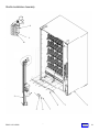
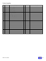
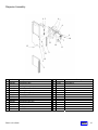
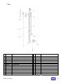
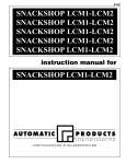
Cabinet
1
12
6
4
5
9
11
16
10
7
8
3
14
15
13
2
Key
Part Number
56600129
56600129-01
56600125
56600192
54400134
5 56900001
6 53100018
7 52200090
8 52000653
9 52000464
10 53100018-01
11 53100026
2
2a
3
4
RQ511 V3.0 05/06
Description
Door Assembly Complete, Thermal. Black
Door Assembly Complete, Thermal. Euro Gray
Monetary Door, see page 5.08
Lamp Assembly complete.
Lamp Cover (not shown)
Lamp – Fluorescent 55 Watt
Screw Hex/Wshr #8
Insulation Base
Deflector Base
Air Deflectors
Screw #8
Washer-Plastic
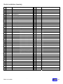
Key Part Number
12
13
14
15
16
420003
420010-19
56400059
420003
56600223
Description
1/4x20x3/4 Screw
Washer
Hinge Pivot Assy.
Screw 1/4x20x3/4
Door Panel, Stick on
BACK
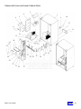
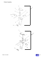
20
Shuttle Installation Assembly
8
9
10
2
4
5
RQ511 V3.0 05/06
6
5.3
3
1
7
BACK
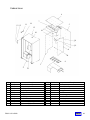
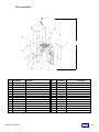
21
Shuttle Installation Assembly
Key Part Number
1
2
3
4
5
6
7
8
9
10
Description
56600161
53400023
102-8R12
56600177
5300054
437-10
420010-9
438-8
164-8-8
Cabinet
Y bar/Carriage Assy.
Rail-Bottom Guide
Screw-#8-32x1/2
Bottom Slide Assy.
Washer-Latch Pin
Keps Nut 10-24
Washer
Keps Nut 10-32
Screw w/lock Washer
56000115
53000106
Leg Assembly (not shown)
Leg Leveler (not shown)
RQ511 V3.0 05/06
Key Part Number
5.4
Description
BACK
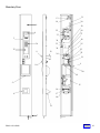
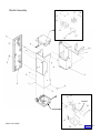
22
Cabinet with Liner and Inside Cabinet Parts
2
4
6
3
1
5
9
10
37
8
11
7
12
15
13
28
14
34
35
16
36
21 18
23
29
22 26
25
17
19
20
30
33
31 32
RQ511 V3.0 05/06
27
5.5
BACK
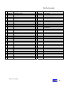
23
Cabinet with Liner and Inside Cabinet Parts
Key
Part Number
Description
Key Part Number
1
2
3
4
5
56600162
56000086
56600102
56600131
56600118
Cabinet Liner Assy.
Air Deflector Assy.
Evaporator Fan / Bracket Assy.
Cover Assy. Evaporator Upper
Cover Assy. Evaporator Lower
33
34
35
36
37
53100025
53100027
53100023
53100024
53100018-01
6
7
8
9
52000437
56800048
53100018
56800003
Cover –Evaporator Fan
Harness Temp. Probe
Screw 8 x 1/2
Line Cord Assy.
38 52000674
10
11
12
13
14
15
16
17
18
19
20
21
22
23
24
25
26
27
28
29
30
31
32
420078-1
56600111
Pop Rivet .125 x .265
Back Vent Screen
Refrigeration Assembly See Page 5.22
Refrigeration Mounting Bracket
Foam Seal 1/2x1/2
Foam Seal
Foam Seal
Screen Assy. Inlet
Bracket Assy. Lower
Bracket Assy. Coin Box
Coin Box
Washer
Guide RH Lower
Guide LH Lower
Bracket Bottom Mounting
Screw –Self Drilling
Screw 8-32x3/4
Barrier Assy. See Page 5.10
Refrigeration Cover,Upper
Refrigeration Cover,Lower
Bracket-Front Barrier
Washer
Spacer Barrier
Description
Bolt
Spacer-Barrier
Washer
Screw-Self Drilling
Screw
Plate-Washer
Harnesses
52000432
53300045
53300043
53300042
56600107
56400044
56000091
56000049
420010-9
53200009
53200008
53200010
53100024-01
53100043
56600165
56600136
56600135
52000400
52000401
53100029
RQ511 V3.0 05/06
39
40
41
42
56800041
56800037
56800038
56800040
3a 56700015
3b 56700015-01
Harness-Compressor Control
Harness-Fan Power
Harness-Junction Box To Light
Harness-Power Extension
117v Fan Only
230v Fan Only
BACK
24
Cabinet Shelving
5
13
14
4
15
16
10
11
1
9
12
7
2
3
6
8
RQ511 V3.0 05/06
BACK
25
Cabinet Shelving
Key
Part Number
Description
1
2
3
4
5
6
7
8
9
10
56600164
56600200
56400087
56600116
56600097
56600117
56600171
53000115
166-8r6
276-10r8
Cabinet Barrier & Chiller Assy.
Double Tray Assy.
Frame Tray
Pusher Right Assy.
Pusher Assy. See Page 5.12
Pusher Left Assy.
Roller Track Assy.
Lock Shelf Component
Screw
10-24x1/2 Screw
11
12
13
14
15
16
56400081
52000652
54000008
53000103
53000070
53000055
Tray Base Assy.
Latch Tray
Spring - Tray Latch
Rivet – Latch
Roller - Tray
Pin Tray Support
17
18
19
20
21
56600163
438-6
56600172
56400041
54400031
Escapement Assy. – Four Post
6-32 Keps Nut
Tray Base – Roller Assy.
Tray Sub-Assembly
Tray Slides
22
23
24
25
26
27
28
29
30
31
32
33
34
53200021
53200019
53200020
53200005
53200022
52000608
53000086
53000085
53000046
53000045
53200025
54000010
57400004
57400005
Base Escapement
Gate Left
Gate Right
Gate Lock Right
Gate Lock Left
Link Gate
Pin Gate Clevis
Pin Gate Link
Pin-Tray Long
Pin-Tray Short
Stop-Bottle
Spring-Four Post
Price Tabs 50-95 (eight of each price) Not Shown
Price Tabs 1.00-1.75 (eight of each price) Not
Shown
Price Tabs 1.80-2.60 (eight of each price) Not
Shown
57400006
RQ511 V3.0 05/06
Key Part Number
35 57400013
Description
Selection Tabs Complete Set (not shown)
BACK
26
Monetary Door
13
31
14
30
1
29
32
28
33
27
4
3
26
34
36
25
35
34
35
9
23
12
22
24
21
1
10
20
19
5
15
16
17
6
18
11
7
8
RQ511 V3.0 05/06
BACK
27
Monetary Door
Key
1
1a
3
3a
3b
3c
4
5
6
7
8
9
10
11
12
13
14
15
16
17
18
19
Part Number
56600125
56000056
16600266
14400034
17400102-01
13800001
440390
54400062
660581
56400075
420003
440289-5
17200002
54400066
56600069
380258
52000411
56600182
420144
305-7R8
420010-17
56000072
RQ511 V3.0 05/06
Description
Key
Monetary Door Assy.
Weldment Monetary Door
Bezel Selector Assy.
Bezel Only
AP Logo For Bezel
Selection Switch Membrane (not shown)
Instruction Glass
Trim-Dispense Door
Coin Cup Front Assy.
Hinge Pivot Assy.
Screw ¼ 20x3/4
Coin Return Button
T-Handle Assy.
Coin Cup
Coin Chute Assy.
Door Switch
Door Switch Bracket
Dispense Door Assy. See Page 5.18
Ferrule
Screw #7x1/2
Washer
Weldment Handwell
5
20
21
22
23
24
25
26
27
28
29
30
31
32
33
34
35
36
37
Part Number
56000055
56400051
118-10-12
438-10
56400034
276-8R6
201660
404-8
18443
52000684
56600001
53300038
360258
56800036
54000011
660580
56000055
14400033-01
Description
Locking Bar Weldment
Lock Arm Assy.
Carriage Bolt 10-24x3/4
Keps Nut 10-24
Extension Rod Coin Return
Screw 8-32x3/8
Coin Return Bracket
Hex Nut 8-32
Nut ¼
Bracket Harness
Board Cover
Foam Seal 3/16x1/2
Control Board
Harness-Service & Compressor
Clip-Wire
Validator Filler Plate
Locking Bar
Keypad Buttons
BACK
28
Barrier Assembly
17
18
1
16
16
2
15
3
16
14
9
22
8
4
7
5
10
19
6
13
11
23
12
20
26
24
28
27
29
30
22
25
RQ511 V3.0 05/06
BACK
29
Barrier Assembly
Key
Part Number
Description
Key
Part Number
Description
1
2
3
4
5
6
54400116
56400048
56600113
56600095
56600035
52000323
Front Panel Assy.
Coin Mech. Support
Power Supply Assy. See Page 5.20
Coin Slide Assy.
Coin Return Chute Assy.
Coin Chute Return
23
24
25
26
27
28
56700009
56400049
53800009
54400096
53800009
54400095
Motor 24v
Mount Home Lock
switch
Cam XYZ Lock
Switch
Bar XYZ Lock
7
8
9
10
11
12
13
14
15
16
17
18
19
20
21
22
56000076
440362
300203
437-41
52000330
4200010-9
53100018-01
53300045
52000316
53300047-01
53100038
56600188
56600093
53100018
53300047
56600084
Security Shield
Shelf Roller
Shelf Roller Screw
¼-28 Keps Nut
Door Lock Catch Bottom
Washer
Screw 8-32 x3/4
Foam Seal 1/2x1/2 64 inches
Door Lock Catch Top
Seal- Wiring Harness
Clip-Wire
Home Switch Assy.
Coin Release Assy.
Screw 8-32x3/8
Seal-Wiring Harness
Home Lock Motor Assy.
29
30
404-2
56800018
Hex Nut 2-56
Harness
RQ511 V3.0 05/06
BACK
30
Pusher Assembly
3
4
9
4
8
2
6
7
8
1
5
9
4
2
7
8
5
6
11
3
9
4
7
10
8
6
5
RQ511 V3.0 05/06
BACK
31
Pusher Assembly
Key
1
2
3
4
5
6
7
8
9
10
11
Part Number
56600097
56600104
56600103
53400010
420078-9
52000408
53000060
262-6R6
52000388
56600117
56600116
RQ511 V3.0 05/06
Description
Key Part Number
Description
Dual Pusher Assy.
Pusher Assy. Right
Pusher Assy. Left
Rail-Pusher
Pop Rivet .125x.375
Spacer - Push Rail
Pin-Pusher Mounting
Screw #6-32x3/8
Latch-Pusher
Pusher Right Assy. Complete
Pusher Left Assy. Complete
BACK
32
Pusher Assembly
4
1
5
7
3
8
6
10
9
2
11
4
1
3
7
6
8
2
9
11
RQ511 V3.0 05/06
10
BACK
33
Pusher Assembly
Key
1
2
3
4
5
6
7
8
9
10
11
12
Part Number
56600104
54400086
54400035
54400085
53100014
305-7R8
54000007
52000506
54400108
53000082
57400011-01
56600103
RQ511 V3.0 05/06
Description
Key Part Number
Description
Pusher Assy. Right
Pusher Assy. Lower
Hub-Spring
Pusher Arm Upper
Roll Pin
Screw #7x1/2
Spring-Pusher
Clip-Pusher
Wheel - Pusher
Pin-Wheel
Label-Sold Out
Pusher Assy.-Left
5
BACK
34
13
Shuttle Assembly
17
16
15
14
5
11
12
18
10
9
6
2
4
3
8
25 26
20A&B
23
22
20
7
21
RQ511 V5.0 05/06
24
19
BACK 35
Shuttle Assembly
Key Part Number Description
Key Part Number
1
2
3
4
5
6
7
8
9
10
56600155
56600153
56000108
54400120
56600151
276-8R8
56600152
276-6R6
53000095
52200095
Shuttle Assy. Complete
Shoe Assy. See Page 5.19
Carriage Weldment
Insulator
Carriage y Drive Assy.
Screw 8-32x3/8
Carriage Z Drive Assy.
Screw 6x3/8
Shaft-Shoe
Saddle
19
20
20A
20B
20C
21
22
23
24
25
26
11
12
13
14
15
16
17
56000120
56700005
52000665
142-4-4
438-6
56000129
53300049
Chassis – Y drive
Motor-Y Axis
Cover-Y drive
Screw #4-40x1/4
Keps Nut 6-32
Clamp
Strip-Tip Abatement
56000111
56700016
53000003
801C094-10
56700003
56800060
53800009
56000107
438-6
404-2
142-4-4
Description
Z Drive Chassis
Asm, Z Drive Motor Includes 20 A, B & C
Gear, Cage Drive, Z – Axis
Roll Pin, 3/32 Dia x 5/8lg
Z Drive Motor, Only
Harness Cage
Switch Robo Cage
Weldment-Z Motor Mounting
Keps Nut 6-32
Keps Nut
Screw #4-40x1/4
RQ511 V5.0 05/06
BACK
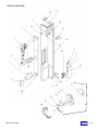
36
Dispense Assembly
4 5
6
7
8
9
10
12
16
15
11
11
13
3
14
1
2
Key Part Number
Description
Key Part Number
1
1a
2
3
4
5
6
7
8
9
10
11
12
13
Dispense Door Assy.
Bracket Only
Door-Dispense
Bracket Dispense Door Guide
Motor Assy.
Harness-Delivery Door
Bracket Dispense Door Motor
Screw 8-32x1/4
Switch
Dispense Door Gear Assy.
Screw 8-32x3/8
Screw #4-40x9/16
Door Track
Stand-Off Door
14
15
16
56600182
52000304
54400061
54400126
56600185
56800034
52000661
276-8R4
53800007
56600183
276-8R6
276-4R9
54400109
53000111
RQ511 V3.0 05/06
217-6R5
203-6R16
142-4-4
Description
Screw #6x5/16
Screw #6x32x7.8
Screw #4-40x1/4
BACK
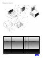
37
Cabinet Liner
6
7
14
11
12 13
5
15
17
10
16
18
19
4
20
8
3
2
21
9
Key
1
2
3
4
5
6
7
8
9
10
11
Part Number
56600162
56600157
57000011
57000012
57000010
57000013
56600143
56000084
54400078
56400060
56400058
RQ511 V3.0 05/06
Description
Key
Cabinet Liner Assembly
Cabinet –Insulated
Liner Cab Left Side
Liner Cab Right Side
Liner Back
Liner Top
Upper Rail Assembly
Lower Shelf Plate
Liner Bottom
Hinge Assembly Upper Right
Hinge Assembly Upper Left
12
13
14
15
16
17
18
19
20
21
Part Number
420349
52200073
164-51-7
27931
53100001
460642
53100018
56400045
276-10R8
27932
Description
Hole Plug
Insulation Hole Plug
Screw w/Lockwasher
Carriage Bolt
Plastic Rivet
Decal - Voltage
Screw Hex 8-32 x 3/8
Bracket Assy.
Screw 10-24 x ½
Nut 5/16
BACK
38
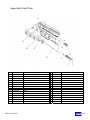
Upper Rail & Shelf Plate
15
9
7
5
6
13
10
8
2
11
14
12
4
3
Key
1
2
3
4
5
6
7
8
9
10
11
12
13
14
15
Part Number
56600143
52000650
56800053
404-61
53100022
53400021
53000021
751-37
276-8R14B
276-8R4
276-8R6
53000107
56000097
56600145
54250003
RQ511 V3.0 05/06
Description
Key Part Number
Description
Upper Rail and Shelf Plate Asm
Bar sensor
Coiled Cable
Hex Nut 3/8
P Clamp 3/8
Top Plate
Rack X Axis
Retaining Ring
Screw
Screw
Screw
Shaft X Cable
Upper Rail Weldment
Upper Slide Assembly
Super Lube Grease (not shown)
BACK
39
Y Bar Assembly
13
12
11
10
2
4
14
5
6
1
9
3
8
7
Key Part Number
Description
1
2
3
4
5
6
7
8
9
10
11
12
13
14
Shuttle Assembly
Y Bar Assembly
Shaft – Y Bar Cord
Harness – Y Bar
Upper Y-Bar Bracket Assembly
#4-40 X 3/8 Flat Head Screw
Actuator – Home Switch
P Clamp
8-32 Keps Nut
Harness – Y Coil Cable
#8 X 32 X ½ Screw
Cable Connection Bracket Assembly
¼ X 20 Keps Nut
#6 X 3/8 Screw
56600155
56600178
53000101
56800045
56400083
242-4R6
53100034
53100022
438-8
56800054
166-8R8
56000123
438-41
276-6R6
RQ511 V3.0 05/06
Key
Part Number
Description
BACK
40
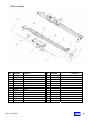
Y bar
4
5
6
7
8
3
9
2
10
1
11
14
12
13
Key Part Number
Description
Key Part Number
1
2
3
4
5
6
7
8
9
10
11
12
13
13a
Y Bar Hardware Assembly
Rack – Y Axis
Carriage to Y Bar Mount Assembly
Bearing – Self Align
Retaining Ring
.094 X 5/8 Steel Dowel
Gear - Mod X Drive
Bearing – Thrust
8-13 Keps Nut
Y Bar Mounting – Gear
#8 X 32 X 3/8 Screw
Shaft – Shuttle
X Drive Mount Assembly
X Motor Only
14
56400082
53000063
56600154
53100005
751-37
803-094-10
53000015
53100004
438-8
53200015
262-8R6
53000102
56600176
56700006
RQ511 V3.0 05/06
56600191
Description
Y Switch Assembly
BACK
41
Shoe Assembly
8
10
6
2
5
1
9
11
7
12
Key
Part Number
Description
1
2
3
4
5
6
7
8
9
10
11
12
56600153
56000109
54400121
56600179
56600180
54400144
53000093
420135-4
305-6R6
276-6R6
5440080
276-4R4
Shoe Assy.
Shoe Weldment
Cage Floor
Bottle Guide Right Assy.
Bottle Guide Left Assy.
Gear-Cage Z -Axis
Actuator Z Drive
Grommet 3/8 Id X 5/8 OD
Screw 6X3/8
Screw 6X3/8
Cam – Cage Roller
Screw #4-40x1/4
RQ511 V3.0 05/06
3
4
Key
Part Number
Description
BACK
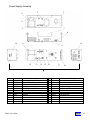
42
Power Supply Assembly
5
2
4
6
3
7
8
10
11
19
9
12
13
14
15 16
17
18
1
Key
1
2
3
4
5
6
7
8
9
10
Part Number
56600113
52000423
56800007
56700008
56800029
276-8R6
56800051
380303
380304
57400008
RQ511 V3.0 05/06
Description
Power Supply Assy.
Enclosure-Power Supply
Transformer-120V
Relay-24V
Harness Power Supply Relay
Screw 8-32x3/8
Light Ballast
Filter-Light
Filter Power Supply
Label
Key Part Number
11
12
13
14
15
16
17
18
19
436-8
380241-2
380243
57400009
56800030
216-41R8
460642
57400010
420040-2
Description
Keps Nut 8-32
Circuit Breaker 5Amp
Switch
Label Power Supply
Harness Junction Box
Screw 1/4x1/2
Decal
Label-Power Cord
Snap Bushing
BACK
43
Refrigeration Assembly
22
20
23
21
24
12
25
19
13
14
6
15 16
18
17
10
11
5
1
9
4
2
3
8
7
Key
1
2
3
4
5
6
7
8
9
10
11
12
13
14
15
Part Number
56600100
56000083
56700010
440459
52100015
52100017
52000422
56800027
300225
420426
54400077
52100012
52100016
420427
52000418
RQ511 V3.0 05/06
Description
Refrigeration Assy.
Refrigeration Base Assy.
Compressor 120 Volt
Evaporator Pan
Discharge Tube
Process Tube
Bracket-Cond. Cover
Harness-Refigeration
Compressor Mounting Pin
Compressor Mounting Clip
Cover
Condensor Coil
Tube
Drier
Condensor Fan Shroud
Key Part Number
16
17
18
19
20
21
22
23
24
25
276-10R8
52000470
460044
56700011
56700022
210-8R6
53300041
420356
52100014
52000421
52100018
Description
10-24x1/2
Bracket-Cond. Motor
Wire Tie
Condensor Fan Assy. 120 Volt
Motor Only, Condensor Fan
Screw #8x3/8
Seal-Ref. Tube
Tubing ½ ID
Capilary Tube
Bracket-Evap. Top
Evaporator Coil Assy.
BACK
44
Troubleshooting
APi RoboQuencher ALIGNMENT & Set-Up Procedure
Tools: Phillips screw driver, straight edge (NOTE: Straight edge can be any item that will give a consistent
measurement, ruler, file, pen or pencil etc.).
Step 1: Align Y bar to shelving
Step 2: Adjust X sensor bar
Step 3: Adjust cage vending height
STEP #1
A. Machine needs to be powered up and at operating
temperature (37F).
Push “service mode” button, located on control board.
Put in test mode (*22)
Push slide to the left, at selection 11. (Fig. 1).
B. Press 10 on the keypad and send to selection 10.
Do NOT extend the cage as this may cause an incorrect reference.
Place straight edge on the right side of shuttle so it touches the slide.
Pick a reference point off of the left edge of the straight edge to either
the slide or other point on gate. The reference point will then be used at
selection 50 to determine if the Y bar is straight with the shelving.
C. Press 50 to go to selection 50.
Use the straight edge and compare the reference point you had at
selection 10. If both references are within 1/8” the Y bar is straight with
the shelving press *1 to go home and proceed to step 2.If the reference
points is off by more than 1/8” you need to move the bottom of the Y bar
in the direction you are off. (proceed to step D)
RQ511 V3.0 05/06
BACK
45
Troubleshooting
D. RE-POSITIONING YBAR
Press *1 to send shuttle home, then press 33 to send shuttle to selection 33.
Loosen (2) screws shown in fig. 5.
Grasp the bottom of the YBAR assembly and pull towards you and shift the bottom of the bar 1 tooth (left or right,
depending on offset found when measuring above).
Tighten screws and send YBAR home (*1).
Repeat steps A through D and verify settings are now the same.
RQ511 V3.0 05/06
BACK
46
Troubleshooting
Step # 2
A. Enter 10 on the keypad, which will send the shuttle to location 10. Align a straight edge from the right side of
shuttle to slide of selection 11.
If the rib is not aligned, measure the difference between the left edge of the straightedge and the left side of rib # 2.
Send back to home (*1), and proceed to step 3.
B. Loosen the 3 screws securing the x timing bar to the top of the cabinet interior. (fig. 3) Move the x sensor bar the
direction that the shuttle needs to move to be aligned with the left edge of rib 2.
Repeat steps A and B to see that x sensor bar is aligned correctly.
Scribe
Scribe alignment
alignment mark
mark
for
for reference
reference
RQ511 V3.0 05/06
BACK
47
Troubleshooting
Y Motion Connector on Control
Board
Trouble Shooting RoboQuenchertm Cage
Product Sensors with a DMM
P9
Test 1 and Test 2 can be done at either P-9 (Fig 1)on the
RQ Control Board OR at the 16 pin connector (Fig 2) on
the left edge of the cage
Test 1 - Check LED:
Power machine off
Unplug Y Motion Control connector
Set meter to diode check
Place red probe on pin 15 of the harness
Place black Probe on pin 16 of the harness
You should read over 1 Volt Å the LED is good
If you reverse the probes you should get nothing
If you get an infinite reading both ways, a harness is
broken or the LED is faulty
Test 2 - Check the sensor:
Power down machine
Unplug Y Motion Control connector
Move the Z Mech to bottom/middle of the machine
Set meter to diode check
Place red probe on pin 14
Place black Probe on pin 11
There should be no reading or infinite reading
The sensor is on the right side of the Z Mech covered by
a small clear cover. You need to take a flash light and
point it in to the sensor. The more light you can provide
directly on the sensor, the lower the voltage.
The meter should go from infinite to some value above 0
volts.
You may have to move the flashlight around so that you
are pointing it into the sensor. If you see the meter leave
the infinite reading the sensor is good.
If you get no reading when checking the Sensor with a
meter and a flashlight, check the harness
from the board to the sensor in cage by performing Test
3.
1
16
9
White w/ Black
Red w/ Black
Green w/ Black
Blue
Figure
screws
sensor
This is the 5Vdc supply to the components in the cage
control
Set meter to volts AC
Place red probe on pin 15
Place black probe on pin 16
You should measure above 0.200 Volts.
control
If the harness to the sensor tests OK, Proceed to
Test 4.
RQ511 V3.0 05/06
Connector viewed as mounted
on left edge of Cage assembly
Test 4 – Control Board Power to Cage
To check control board:
Machine should be powered up
Set meter to volts DC
Place red probe on pin 15 (Y motion Control)
Place black probe on pin 13 (Y motion Control)
You should measure 5 Vdc
Test 3 - Continuity of Sensor & Harness:
Remove right bottle guide by removing the two
located on the right side of the Z Mech
Move the bottle guide so you can access the
wires in back
Blue wire (pin 1) in Z Mech goes to y motion
connector pin 11
White wire (pin2) in Z Mech goes to y motion
connector pin 14
Figure 1
This is the pulsed signal being sent to the LED in the
cage. If no voltage is detected, replace control board.
BACK
48
Troubleshooting
Robo Quencher Lubrication And Maintenance Schedule
The following illustrations show the lubrication points that we recommend be cleaned and
lubed at the vend counts listed on the attached chart. The recommended lubricant is Super
Lube part # 54250005, for the gear racks, and mineral oil for the shelf slides and X&Y bars.
Figure 1
RQ511 V3.0 05/06
BACK
49
Troubleshooting
Figure 3
Figure 2
Figure 5
Figure 4
BACK
RQ511 V3.0 05/06
50
Troubleshooting
PREVENTATIVE MAINTENANCE
SERVICE SCHEDULE
for APi 511 Beverage Merchandiser
SERVICE REQUIRED AT EACH
INTERVAL LISTED X MONTHS OR
VENDS WHICHEVER COMES FIRST
Intervals by
Months >>>
Each Visit
Intervals by
Vends >>>
3
6
12
18
5,000
10,000
20,000
30,000
Clean/Inspect
Clean/Inspect
Clean/Inspect
Clean/Inspect
Oil
Oil
Oil
Replace
Replace
Replace
Oil
Oil
Oil
Shuttle assembly (See Fig. 1)
Shuttle shoe, and sensors
Clean
Lube the 4 black slider blocks ( Y bar)
Foam pad
Inspect
Lower x bar slide assy. (See Fig.2)
Lube the bottom rail guide
Lube the bottom gear rack
Grease
Lube the bottom x motor slides
Oil
Oil
Oil
Oil
Oil
Oil
Upper x bar slide assy. (See Fig.3)
Lube the upper rail guide
Lube the upper gear rack
Grease
Lube the upper x rail slides
Oil
Oil
Oil
Clean/Lube
Replace
Clean/Lube
Replace
Inspect
Inspect
Inspect
Inspect
Clean
Clean
Clean
Clean
Shelf Tray assy. (See Fig.4)
Shelf slides
Bottle Escapements (40)
Inspect
MISCELLANEOUS (See Fig.5)
Intake screen
Clean
Exhaust screen
Coin Mech. And Validator
Clean
T-Handle
Glass Door
Lubricate
Clean
Condensing Unit Fins
Any Spills
Clean
Clean
For each month of use past 36 months, repeat the schedule at each interval indicated.
CLEAN
INSPECT
Clean and sanitize as per Each Visit procedure found on previous pages.
Visually inspect parts if there is a problem remove assembly from machine and
Thoroughly clean, and inspect for wear or bent parts. If necessary: repair, adjust,
clean, rebuild or replace.
REPLACE Recommended interval for replacement.
REBUILD Remove from machine, disassemble, clean and replace worn or corroded parts.
LUBRICATE Should be cleaned, inspected, and repaired before lubrication. Recommended
Lubricant is a food grade, light weight mineral oil.
RoboQuenchertm
RQ511 V3.0 05/06
BACK
51
Troubleshooting
Temperature Probe Test
Press and hold either the ► (F°) or ◄ (C°) to read the
reported current temperature.
Temperature
(Deg F)►
37
45
55
60
65
70
If the temperature reads 255, that indicates that the
temperature probe harness is disconnected from the
board, or the probe harness has a broken wire.
To Test Temperature Probe for correct reading.
Set Meter to less than 5Vdc scale.
With machine power on, check pins P4-1 (-) to P4-4 (+)
for 5Vdc – If no voltage is present – check for 24Vac at
P1-1 & P1-3
Check pins P4-1 to P4-3 for a value as indicated on the
chart above, depending upon the temperature inside the
cabinet. A correct value indicates that the temperature
probe is functioning correctly.
If the refrigeration unit is not running and the cabinet
temperature is more than 5° above the set point, check
P6-4 (+)and P6-5 (-)for 24Vdc, and check 4 pin connector
on bottom of power box for 120Vac, between pins 1 and
3.
Temperature
(Deg C)◄
2.8
7.2
12.8
15.5
18.3
21.1
Voltage
(Volts)
0.384
0.444
0.544
0.589
0.637
0.691
Temperature vs. Voltage
70
65
Temperature (Deg F)
60
55
50
45
40
35
0.384
0.444
0.544
0.589
0.637
0.691
Voltage (volts)
RQ511 V3.0 05/06
BACK
52
Troubleshooting
During
Reset
E0
E2
E3
During a
vend
60
62
63
E4
64
E5
65
E7
E8
E9
EA
EC
ED
F0
F1
67
68
69
6A
6C
6D
50 or 70
51 or 71
F3
53 or 73
F4
54 or 74
F5
55 or 75
F6
56 or 76
F7
57 or 77
F8
58 or 78
F9
59 or 79
FA
5A or 7A
FB
5B or 7B
5C
or
7C
FC
FF
Error Meaning
Solution
Too many critical errors too fast
Y home switch not found
At lease one lock switch stuck on
Y motor over current
Clear errors, Power down, power up, allow machine to initialize
Check P9, check Y home switch & harness
Check that both switches are not both on at the same time, check P1
Clean and re-lubricated "Y" bar and drive rod. Check for any
obstructions on "Y" bar gear rack and glides. Check that the Y coil cable
is free to move. Replace shuttle assembly.
X motor over current
Clean and re-lubricate lower and upper "X" drive gear rack and slides.
Check that the X home switch actuator is set properly. Check for any
obstructions. Check that the X coil cable is free to move.
Y motor out of control
Check P9, replace control board, replace shuttle assembly
X motor out of control
Check P1, check motor wires, replace control board
Lock motor out of control
Check P1, check motor and switch wires, replace control board
Z Mech motor out of control
Check P9, replace shuttle assembly, replace control board
Product vend door can’t open
Check P5 on board, check motor and switch wires, clean track
Product vend door can’t Close
Check P5 on board, check motor and switch wires, clean track
Encoder pulses too fast
Check P9, replace shuttle assembly
X home switch stuck
Check for obstruction holding switch closed, replace switch
X Home switch noise
Clean and re-lubricate lower and upper "X" drive gear rack and slides.
Check that the X home switch actuator is set properly. Check for any
obstructions. Check that the X coil cable is free to move.
X motor over current at start-up
Clean and re-lubricate lower and upper "X" drive gear rack and slides.
Check for any obstructions. Check that the X coil cable is free to move.
Lock motor over current at start-up Check motor, replace control board
Z Mech motor over current at start- Check P9, check motor and switch wires, replace shuttle assembly,
up
replace control board
Y motor over current or bad Clean and re-lubricated "Y" bar and drive rod. Check for any
encoder
obstructions on "Y" bar gear rack and glides. Check that the Y coil cable
is free to move. Check P9, replace shuttle assembly, replace control
board
X is binding, but not over current Clean and re-lubricate lower and upper "X" drive gear rack and slides.
Check that the X home switch actuator is set properly. Check for any
obstructions. Check that the X coil cable is free to move. Re-adjust
upper "X" bar guide to reduce "Y" bar twist. Check "X" motor gear box.
Lock motor is binding, but not over Check for obstructions
current
Z Mech motor is binding, but not Check for obstructions
over current
Z Mech in/out switch stuck
Check switches, replace shuttle assembly
Product vend door out of control Check P5 on board, check motor and switch wires, replace control board
Both Z switches stuck on
Temperature shows greater than Probe unplugged
250 oF
Machine is warm
Check P6, pins 4 & 5 for 24VDC
Check 2 pin connector for Refrigeration Relay on Power Box
Check 4 pin connector to refrigeration unit on Power box for 120VAC
between pins 1 & 3
Machine is dark, no digits on Check wall outlet for correct voltage
display
Check incoming power cord at power box
Check power cord connector adjacent to refrigeration unit
Fd on display
Health Code has been tripped, power machine off and on to reset Health
Fd
Fd
Code.
Determine cause for Health Code intervention.
53
BACK
RQ511 V3.0 05/06
Troubleshooting
Clear Errors in a Roboquencher 511
1. Press Mode switch 1 time.
2. If errors are present, display will show nXX, where XX equals the number of errors present, up to a
maximum of 15.
3. To view the errors, press the right arrow key, and the error code will show on the display, in order
from most recent to earliest.
4. After the last error, the display will show cLrn (Clear N), press the # key to toggle this to cLrY (Clear
Y), and then press the C to finish clearing errors.
BACK
54
Troubleshooting
ELECTRICAL CONNECTIONS
P1
1
2
3
4
5
6
7
8
9
10
11
12
13
14
15
16
XMOTION CONTROL
MOTOR X
MOTOR X COMMON
KEY
LOCK MOTOR
LOCK MOTOR COMMON
Y HOME SWITCH COMMON
Y HOME SWITCH
X POSITION SENSOR GROUND
X POSITION SENSOR SIGNAL
X POSITION +5 SUPPLY
SENSE SWITCH: SHELF INTERLOCK
X POSITION SENSOR LED DRIVE
X MOTOR HOME SWITCH
GROUND FOR SENSE SWITCHES
SENSE SWITCH: LOCK MOTOR LOCKED
SENSE SWITCH: LOCK MOTOR FREE
P2
1
2
3
4
5
6
7
MDB
34VDC
KEY
PWR GROUND
MASTER RXD
MASTER TXD
COMMUNICATION COMMON
N/C
P3
1
2
3
POWER
24 VAC
EARTH GROUND
24 VAC
P4
1
2
3
4
TEMPERATURE SENSOR
GROUND
KEY
TEMPERATURE SIGNAL
5 VDC
P5
DELIVERY DOOR
1
DELIVERY DOOR OPEN
2
DELIVERY DOOR CLOSE
3
KEY
4
DELIVERY DOOR SWITCH OPEN
5
DELIVERY DOOR SWITCH CLOSE
DELIVERY DOOR SWITCH COMMON
P6
1
2
3
4
5
SERVICE
DOOR SWITCH COMMON
KEY
DOOR SWITCH
24 VDC
REFRIGERATION RELAY CONTROL
RQ511 V3.0 05/06
P7
1
2
3
RS232 SERIAL INTERFACE (PHONO PLUG)
RECEIVE DATA
GROUND
TRANSMIT DATA
P8
1
2
3
4
5
6
7
8
9
10
KEYPAD
ROW 1
ROW 2
ROW 3
ROW 4
ROW 5
KEY
COLUMN 1
COLUMN 2
COLUMN 3
COLUMN 4
P9
1
2
3
4
5
6
7
8
9
10
11
12
13
14
15
16
Y/Z MOTION CONTROL
MOTOR Y FORWARD
MOTOR Y REVERSE
Z MECH MOTOR OUT
Z MECH MOTOR IN
KEY
Z MECH SWITCH IN
Z MECH SWITCH OUT
Z MECH SWITCH COMMON
Y POSITION 5 V
Y POSITION SENSOR A
Y POSITION GROUND
Y POSITION SENSOR B
GROUND
PRODUCT PRESENT SENSOR
PRODUCT PRESENT LED +
PRODUCT PRESENT LED
KEYPAD MATRIX
Switch #
1
2
3
4
5
6
7
8
9
*
0
#
<C
->
Connection A
PIN 1
PIN 1
PIN 1
PIN 2
PIN 2
PIN 2
PIN 3
PIN 3
PIN 3
PIN 4
PIN 4
PIN 4
PIN 5
PIN 5
PIN 5
Connection B
PIN 7
PIN 8
PIN 9
PIN 7
PIN 8
PIN 9
PIN 7
PIN 8
PIN 9
PIN 7
PIN 8
PIN 9
PIN 7
PIN 8
PIN 9
BACK
55
5
4
3
2
1
LOCK MOTOR
56800018
1
2
3
4
5
6
1
2
3
4
5
6
*1
NC
*2
NC
UNLOCKED
TRANSMISSIVE X POSITION DETECTION
1
2
3
4
5
1
LOCKED
53600002
DEBIT
CARD
READER
1
1
1
1
1
2
3
4
1
2
3
4
NC
8
7
6
5
4
3
2
1
X MOTOR
2
1
56700006
56800048
16
15
14
13
12
11
10
9
8
7
6
5
4
3
2
1
56800007
P2
MDB
1
2
3
1
2
3
P3
POWER
24VAC
1
2
3
OVERLOAD
DELIVERY DOOR
1
2
3
4
P4
TEMPERATURE SENSOR
KEY
P5
DELIVERY DOOR
1
2
3
4
SERVICE
SWITCH
DEXUCS
PORT
P8
KEYPAD
1
2
3
4
1
2
3
1
2
3
56800030
P9
Y MOTION CONTROL
56800037
56700029
KEY
A
24 VDC
REFRIDGERATION
RELAY CONTROL
Y MOTOR ENCODER
D
G ND
*1
56800053
2
1
24 VDC
s1
s2
s3
s4
s5
s6
s7
s8
s9
s*
s0
1
2
3
4
5
6
7
8
9
10
11
12
13
14
15
16
1
2
3
4
5
6
7
8
9
10
11
12
13
14
15
16
2
1
FILTER
56800047
56800054
1
2
3
4
5
6
7
8
9
10
11
12
13
14
15
16
POWER SWITCH
1
2
*1
Y MOTOR
1
2
3
4
5
13800001
1
2
B
PHASE A
5V
PHASE B
KEY
B
R5
R4
R3
R2
R1
C3
C2
C1
NC
REFRIDGERATION
RELAY CONTROL
1
2
3
4
2
1
P6
SERVICE
56800036
A
1
2
3
4
CONDENSING UNIT
2
1
*1
DOOR CLOSE
56800041
16
15
14
13
12
11
10
9
8
7
6
5
4
3
2
1
DOOR OPEN
1
2
3
4
5
C
PARTS IN DASHED LINES ARE IN THE POWER BOX
F AN
56800027
10
9
8
7
6
5
4
3
2
1
KEY
1
2
3
5 Amp
Breaker
56600013
NO
1
2
3
RELAY
EVAP FAN
CONTROLLER
56800034
1
2
3
4
5
6
117VAC
24VAC
*1
KEY
FILTER
56800042
P1
X MOTION CONTROL
1
2
3
4
5
6
7
C
MAIN DOOR
56800051 FOR 117 VOLT SYSTEMS
56800032 FOR 230 VOLT SYSTEMS
1
2
3
4
2
1
KEY
MULTI DROP BUS
TEMPERATURE
SENSOR
NC
D
BALLAST
KEY
*2
56900001
*2
Y HOME SWITCH
8
7
6
5
4
3
2
1
680576
AND
680642
1
2
LIGHT
56800033
COIN MECH
1
2
1
2
3
4
56800038
56800045
56800053
BILL
ACCEPTOR
1
2
3
4
4
*1
NO
2
X HOME SWITCH
D
FILTER
56700005
1
2
3
4
5
6
7
8
9
10
11
12
13
14
15
16
56800003
56800040
1
2
1
2
1
2
3
CAGE MOTOR
1
2
3
1
2
3
1
2
3
56700003
117VAC
*1
s#
NO
CAGE IN SWITCH
NO
*2
CAGE OUT SWITCH
Y CONTROL
s<
sC
s>
CARRIAGE
GROUND
FRAME
GROUND
D
C
REV
TITLE
A
360267
LED PCB
THIS DOCUMENT CONTAINS INFORMATION
WHICH IS PROPRIETARY TO GROSS-GIVEN
MANUFACTURING. NO REPRODUCTION OR
PUBLICATION OF THIS DOCUMENT IN WHOLE
OR IN PART SHALL BE MADE WITHOUT THE
WRITTEN APPROVAL OF GROSS-GIVEN MFG.
NOTES;
2
1
*1. WHEN THE MACHINE IS POWERED AND READY TO VEND IN NORMAL OPERATE MODE THIS
SWITCH IS ACTIVATED.
2
1
WIRE FOR PIN 13 P9 WENT TO WRONG LOCATION
RELEASE TO PRODUCTION
REVISION DESCRIPTION
1
2
1
2
*2. WHEN THE MACHINE IS POWERED AND READY TO VEND IN NORMAL OPERATE MODE THIS
SWITCH IS DEACTIVATED.
TOLERANCES (EXCEPT AS NOTED)
X
+/- 0.500
X.X
+/- 0.250
HOLE DEC. +/- --X.XX
+/- 0.125
X.XXX +/- 0.062
ANGLES +/- ---
DATE
Gross-Given Mfg Co
300 Jacksonville Rd
Warminster, PA 18974
4
3
11-22-02
07-16-02
DATE
S2002287
S2002150
E.C.N.
A
2
SHEET
1
OF
CHECKED BY
J CHASE
SIZE
1
DO NOT SCALE
DRAWING
DRAWN BY
07-16-2002
75 West Plato Blvd
St . Paul, MN 55107
5
JC
JC
BY
DIAGRAM AP511 MACHINE WIRING
360268
SENSOR PCB
C
DOCKTER
PART NUMBER
57600001
REV
D
1
BACK
56