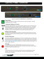
1
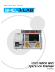
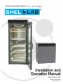
BOD INCUBATORS 100 - 120 Voltage Installation and Operation Manual SRI3P, SRI6P, SRI20P Previously Designated LI3PW, LI6P, LI20P Sheldon Refrigerated BOD Incubators 100 – 120 Voltage Installation and Operation Manual Revision: February 9, 2015 Pictured on Cover: SRI20P (left) - SRI6P (right) SRI3P These units are TÜV CUE listed as incubators and radiant warmers for professional, industrial, or educational use where the preparation or testing of materials is done at approximately atmospheric pressure and no flammable, volatile, or combustible materials are being heated. These units have been tested to the following requirements: CAN/CSA C22.2 No. 61010-1:2012 CAN/CSA C22.2 No. 61010-2-010 + R:2009 UL 61010A-2-010:2002 UL 61010-1:2012 EN 61010-1:2010 EN 61010-2-010:2003 2|Page TABLE OF CONTENTS INTRODUCTION........................................................................................................................................... 4 General Safety Considerations ................................................................................................................. 4 Engineering Improvements ....................................................................................................................... 5 Contacting Assistance ............................................................................................................................... 5 RECEIVING YOUR INCUBATOR ................................................................................................................ 6 Inspecting the Shipment ............................................................................................................................ 6 Orientation Photos..................................................................................................................................... 7 Recording Data Plate Information ........................................................................................................... 10 INSTALLATION .......................................................................................................................................... 11 Location ................................................................................................................................................... 11 Power Source .......................................................................................................................................... 11 Lifting and Handling ................................................................................................................................ 12 Leveling ................................................................................................................................................... 12 Access Port Stopper ............................................................................................................................... 12 Initial Cleaning and Deionized Water ...................................................................................................... 13 Install Side Air Ducts SRI20P .................................................................................................................. 13 Shelving Installation ................................................................................................................................ 14 GRAPHIC SYMBOLS ................................................................................................................................. 17 CONTROL PANEL OVERVIEW ................................................................................................................. 19 OPERATION ............................................................................................................................................... 20 Theory of Operation ................................................................................................................................ 20 Preparing the Incubator ........................................................................................................................... 22 Disable the OTL ...................................................................................................................................... 23 Set the Temperature Set Point ................................................................................................................ 23 Calibrate the Temperature display .......................................................................................................... 24 Set the Over Temperature Limit .............................................................................................................. 26 Turn Alarm Off / On ................................................................................................................................. 27 Loading the Incubator ............................................................................................................................. 29 Interior Accessory Outlet ......................................................................................................................... 29 Humidifying the Incubator ....................................................................................................................... 29 Managing Condensation ......................................................................................................................... 30 USER MAINTENANCE ............................................................................................................................... 31 Cleaning and Disinfecting ....................................................................................................................... 31 Maintaining Atmospheric Integrity ........................................................................................................... 32 Electrical Components ............................................................................................................................ 32 UNIT SPECIFICATIONS............................................................................................................................. 33 Weight ..................................................................................................................................................... 33 Dimensions .............................................................................................................................................. 33 Capacity .................................................................................................................................................. 33 Shelf Capacity by Weight ........................................................................................................................ 34 Temperature ............................................................................................................................................ 34 Power ...................................................................................................................................................... 34 PARTS AND CONSUMABLES .................................................................................................................. 35 3|Page INTRODUCTION Thank you for purchasing a Sheldon Manufacturing refrigerated BOD Peltier incubator. We know that in today’s competitive marketplace, customers have many choices when it comes to constant temperature equipment. We appreciate you choosing ours. Our continued reputation as a leading laboratory product manufacturer rests with your satisfaction. Sheldon Manufacturing, Inc. stands behind our products, and we will be here if you need us. These incubators are intended for professional, industrial, or educational use as BOD incubators. They are not designed for use in hazardous or household locations. Before using the incubator read this manual in its entirety to understand how to install, operate, and maintain the incubator in a safe manner. Keep this manual available for use by all incubator operators. Ensure that all operators are given appropriate training before the incubator begins service. Note: This unit is not designed or intended for the growth, cultivation, incubation, or storage of fruit flies (Drosophila melanogaster). Improper use of this unit, including use with fruit flies, will void any warranty. Other model types are specifically manufactured for fruit fly applications, Consult your distributor or customer service representative to identify a model suitable for your application. GENERAL SAFETY CONSIDERATIONS Note: Failure to follow the guidelines and instructions in this manual may create a protection impairment by disabling or interfering with the unit safety features. This can result in injury or death. Your incubator and its recommended accessories are designed and tested to meet strict safety requirements. Only use this equipment for its intended application. Any alterations or modifications void the warranty. For continued safe operation of your incubator always follow basic safety precautions including: Follow all local ordinances in your area regarding the use of this incubator. If you have any questions about local requirements, please contact the appropriate local agencies. The power supply for the unit must be an earth grounded electrical outlet that conforms to national and local electrical codes. If the incubator is not grounded properly, parts such as knobs and controls can conduct electricity and cause serious injury. Always use the power cord supplied with the unit or an identical replacement cord. Avoid damaging the power cord. Do not bend it excessively, step on it, or place heavy objects on it. A damaged cord can be a shock or fire hazard. Never use a power cord if it is damaged. Position the unit so that the user can quickly unplug the cord in the event of an emergency. Use only approved accessories. 4|Page INTRODUCTION (CONTINUED) ENGINEERING IMPROVEMENTS Sheldon Manufacturing continually improves all of its products. As a result, engineering changes and improvements are made from time to time. Therefore, some changes, modifications, and improvements may not be covered in this manual. If your unit’s operating characteristics or appearance differs from those described in this manual, please contact your Shel Lab dealer or distributor for assistance. CONTACTING ASSISTANCE If you are unable to resolve a technical issue with your incubator, please contact Sheldon Technical Support. Phone hours for Sheldon Technical Support are 6am – 4:30pm Pacific Coast Time (west coast of the United States, UTC -8). Please have the following information ready when calling or emailing Technical Support: the model number and the serial number (see page 10). EMAIL: [email protected] PHONE: 1-800-322-4897 extension 4, or (503) 640-3000 FAX: (503) 640-1366 Sheldon Manufacturing INC. P.O. Box 627 Cornelius, OR 97113 5|Page RECEIVING YOUR INCUBATOR Before leaving the factory, all incubators are packaged in high-quality shipping materials to provide protection from transportation-related damage. When a unit leaves the factory, safe delivery becomes the responsibility of the carrier. Damage sustained during transit is not covered by the warranty. This makes it important that you inspect your incubator for concealed loss or damage to its interior and exterior when receiving it. If you find any damage to the unit, follow the carrier’s procedure for claiming damage or loss. The orientation photos found on the following pages may serves as a useful visual guide for inspections. INSPECTING THE SHIPMENT Carefully inspect the shipping carton for damage. Report any damage to the carrier service that delivered the incubator. If the carton is not damaged, open the carton and remove the contents. The unit should come with an Installation and Operation Manual, warranty card, and a Certificate of Compliance. Verify that the correct number of the following accessories are present: Model Shelves Shelf Mounts Shelf Mounts SRI3P 2 8 Clips -- SRI6P 2 4 Standard Brackets -- SRI20P 5 8 Standard Brackets 2 Sliding Brackets Model Leveling Feet Access Port Stopper* Side Air Duct Panels SRI3P 4 1 0 SRI6P 4 1 0 SRI20P 4 1 2 An 115V 2.5 meter, NEMA 5-15P power supply cord. *The stopper should come installed in the access port, inside the unit incubation chamber. The incubator requires a temperature reference thermometer accurate to at least 0.1°C for performing temperature display calibrations. The reference sensor must be purchased separately. For best results, use a digital reference device with a wire sensor probe to take remote readings. Remote readings can potentially offer an hour or more of time savings during each calibration. Do not use an alcohol thermometer. Please see the Calibration procedure on page 24 of the Operation section. Carefully check all packaging before discarding. Save the shipping carton until you are sure everything works properly. 6|Page RECEIVING YOUR INCUBATOR (CONTINUED) ORIENTATION PHOTOS Peltier Thermoelectric Heater – Chiller Housing SRI20P Control Panel Door Gasket Power Inlet for Cord, Fuse, and Data Plate (Back of the Incubator) Drain Port TEC Housing Incubation Chamber Door Temperature Sensor Probes Access Port Chamber Power Outlet Shelf Standard Rail Sliding Shelf Mount 7|Page RECEIVING YOUR INCUBATOR (CONTINUED) SRI6P Peltier Thermoelectric Heater – Chiller Housing Control Panel Power Inlet for Cord, Fuse, and Data Plate (Back of the Incubator) Temperature Sensor Probes Drain Port TEC Housing Chamber Power Outlet Access Port 8|Page Door Gasket Incubation Chamber Door RECEIVING YOUR INCUBATOR (CONTINUED) SRI3P Peltier Thermoelectric Heater – Chiller Housing Control Panel Door Gasket Power Inlet for Cord, Fuse, and Data Plate Temperature Sensor Probes Incubation Chamber Door Chamber Power Outlet Drain Port - TEC Housing Access Port Shelf Standard Rail 9|Page RECEIVING YOUR INCUBATOR (CONTINUED) RECORDING DATA PLATE INFORMATION The data plate contains the incubator model number and serial number. Record this information for future reference. On the SRI6P and SRI20P the data plate is located on the back of the unit, on the top right side. On the SRI3P the data plate is on the right side of the unit, at the top next to the power cord inlet. Data Plate Date Plate Information Model Number Serial Number 10 | P a g e INSTALLATION This incubator is intended for use indoors, at room temperatures between 15C and 30C (59F and 86F), at no greater than 80% Relative Humidity at 25C (77F). Allow a minimum of 4 inches (10cm) between the incubator and walls or partitions and 2 inches (5cm) of clearance above the top of the incubator for unobstructed airflow. Position the unit so the end-user has access to the power plug. Operating the unit outside of these conditions may adversely affect the temperature range and stability. For conditions outside of those listed above, please contact your distributor or Sheldon Sales to explore other incubator options suited to your laboratory or production environment. LOCATION When selecting a location to install the incubator, consider all environmental conditions that can affect the effective temperature range, uniformity, and stability of the unit. For example: Ovens, autoclaves, and any device that produces significant radiant heat Heating and cooling ducts, or other sources of fast moving air currents High-traffic areas Direct sunlight POWER SOURCE Note: The electrical supply to the incubator must conform to all national and local electrical codes. Always position the unit so that the end-user has access to the power cord in the event of an emergency. When selecting a location for an SRIP incubator verify that the earth-grounded wall power source matches the voltage and ampere requirements listed on the incubator data plate. Supplied voltage must not vary more than 10% from the data plate rating. Damage to the incubator may result if supplied voltage varies more than 10%. Damage from a power supply that does not match the data plate requirements is not covered by the manufacturing defect warranty. Use a separate circuit to prevent loss of product due to overloading or circuit failure. These incubators are intended for a 50/60 Hz application at the following amperages: SRI3P SRI6P SRI20P 4 Amps 4 Amps 5.5 Amps These units are provided with an 115V 2.5 meter, NEMA 5-15P power supply cord. 11 | P a g e INSTALLATION (CONTINUED) LIFTING AND HANDLING An SRIP Incubator should only be lifted by its bottom surfaces using proper heavy lifting machinery such as, a forklift or pallet jack. Handles and knobs are inadequate for lifting or stabilization. The unit should be completely restrained from tipping during lifting. Transporting the unit while lifted is not recommended and may be hazardous. Remove all moving parts, such as shelves and trays, and secure the door in the closed position prior to lifting the unit. Do not attempt to move the unit while in operation or before the unit has cooled. LEVELING The SRIP Incubator must be level and stable for safe operation. Each incubator ships with four leveling feet. Insert one leveling foot into each of the four holes in the bottom corners of the workstation. Adjust the foot at each corner until the workstation stands level and solid without rocking. To raise a foot, turn it in a counterclockwise direction; to lower a foot, turn it in a clockwise direction. To prevent damage to feet while in transport, turn all the feet to the maximum counterclockwise position. ACCESS PORT STOPPER Each SRIP incubator is provided with an access port located back wall of the incubation chamber. The incubator is shipped with one rubber access port stopper installed in the port inside the chamber. The stopper should always be installed in the chamber side to obtain the best temperature uniformity and prevent condensation from forming inside the port. A second stopper may be installed on the outside of the unit to prevent dust from building up in the port, but is not required. Wires for thermocouples and other sensor probes may be introduced into the chamber the access port. The stopper may be put in place over the wire. Seal any gaps using a non-adhesive tape that will not leave adhesive residue when removed. The port stopper must be in place during operation for the incubation chamber to achieve its specified temperature stability and uniformity levels. 12 | P a g e INSTALLATION (CONTINUED) INITIAL CLEANING AND DEIONIZED WATER The incubator interior was cleaned at the factory but not sterilized. It may have been exposed to contaminants en route during shipping. Cleaning and disinfecting the chamber and shelving (as well as the air duct panels of the SRI20P) prior to placing the unit in operation lowers the chance of microbiological contamination. See the Cleaning topic in the User Maintenance section (page 31) for more information on how to clean and disinfect the incubation chamber. Remove all wrappings and coverings from shelving prior to cleaning and installation. Never use deionized water for cleaning the incubator! While DI water is useful in variety of laboratory applications, it is an aggressive solvent that attacks most metals. Use of DI water voids the manufacturing defects warranty. Use of distilled water in the resistance range of 50K Ohm/cm to 1M Ohm/cm, or a conductivity range of 20.0 uS/cm to 1.0 uS/cm is recommended for cleaning applications. INSTALL SIDE AIR DUCTS SRI20P Two (2) side air duct panels are included in the SRI20P accessories. Place the hooks on the top and bottom corners of the panels into the slots provided on the shelf standard mounting rails. The SRI3P and SRI6P incubator do not require side ducts. Figure 1: SRI20P Air Duct Panel Note: The air duct panels play an important role maintaining even heat distribution inside the long incubation chamber of the SRI20P. Failure to install both air duct panels may adversely impact the chamber temperature uniformity. 13 | P a g e INSTALLATION (CONTINUED) SHELVING INSTALLATION SRI3P Shelf Installation Perform the following steps to install the SRI3P incubator’s wire basket shelves: 1. Install the shelf clips in the slots located on the shelf standards (mounting rails) of the chamber interior, both front and back. 2. Squeeze each clip, insert the top tab first, and then the bottom tab using a rocking motion. 3. Hang the wire shelves from the clips. Figure 2: SRI3P Shelving Clips 14 | P a g e INSTALLATION (CONTINUED) SRI6P and SRI20P Standard Shelving Installation Perform the following steps to install the SRI6P and SRI20P incubator standard shelves: Figure 3: Standard Shelf Mounting Bracket Installation 1. Insert the 2 pairs of tabs on the bracket (front and back) into the slots on the shelf standards rails of the incubator chamber. 2. Slide the bracket down so that the tabs are securely seated in the mounting slots. 3. Repeat the process on the opposite side of the chamber with the second mounting bracket. 4. Hang one shelf off the two installed mounting brackets. Figure 4: Standard Mounting Figure 5: Standard Shelf Hung Bracket Installed From Mounting Bracket 15 | P a g e INSTALLATION (CONTINUED) SRI6P and SRI20P Sliding Shelf Installation Note: The SRI6P does not come with a sliding shelf. Sliding shelves for the SRI6P must be purchased separately. Figure 6: Sliding Shelf Mounting Bracket Installation Figure 7: Sliding Shelf Mounting Bracket Installation 1. Insert the sliding bracket’s two pairs of tabs (front and back) into the slots on the shelf standards. See Figure 6. 2. Slide the bracket down so that the tabs are securely seated in the mounting slots. See Figure 7. 3. Secure the bottom flange of the sliding bracket to the shelf standard rails by threading and screwing in 2 screws, on the front and back of the flange. See Figures 8 and 9. 4. Repeat the process on the opposite side of the chamber with the second sliding mounting bracket. 5. Hang 1 shelf from the 2 installed sliding brackets. Figure 8: Sliding Mounting Bracket Screws 16 | P a g e Figure 9: Sliding Mounting Bracket Front Screw Installed GRAPHIC SYMBOLS The incubator is provided with graphic symbols on its interior and exterior surfaces. These symbols identify hazards, as well as the functions of the adjustable components, and important notes in the user manual. Symbol Definition Indicates that you should consult your service manual for further instructions. Indique que l'opérateur doit consulter le manuel d'utilisation pour y trouver les instructions complémentaires. Indicates Temperature Repère température Indicates the Over Temperature Limit system Indique le système de dépassement de temperature Indicates AC Power Repère le courant alternatif Indicates I/ON and O/OFF I repère de la position MARCHE de l'interrupteur d'alimentation O repère de la position ARRÊT de l'interrupteur d'alimentation Indicates protective earth ground Repère terre électrique Indicates UP and DOWN respectively Touches de déplacements respectifs vers le HAUT et le BA Indicates Manually Adjustable Indique un bouton réglable manuellement Indicates Potential Shock Hazard Signale danger électrique 17 | P a g e GRAPHIC SYMBOLS (CONTINUED) Symbol Definition WEEE Directive compliant logo Indicates the unit should be recycled (Not disposed of in land-fill) Indique l’appareil doit être recyclé (Ne pas jeter dans une décharge) 18 | P a g e CONTROL PANEL OVERVIEW Figure 10: Control Panel SRI6P SRI20P Top | SRI3P Bottom Power Switch The green power switch on the panel controls all power to the unit and its systems. The switch illuminates when in the I on position. Temperature Display and Controls Marked SET TEMPTERATURE, the incubation chamber temperature controls comes with a green digital display that shows the air temperature within the chamber, accurate to 0.1°C. The display can also show an adjustable temperature set point, as well as display value adjustments during temperature calibrations. The controls consist of an up / down arrow pad for inputting a new temperature set point, performing calibrations, and turning the door open alarm off or on. Heating and Cooling Light The green pilot light located beneath the label TEC ACTIVATED illuminates whenever the Peltier TEC-H device is actively cooling or heating the chamber. This light will illuminate frequently during normal operations. Set Over Temperature This control is equipped with a graduated dial. The OTL is a mechanical heating cut off system that operates independently of the digital temperature controller. It guards against a failure of the digital controller that would allow the chamber temperature to rise past the controller set point. Please see the Over Temperature Limit System description in the Theory of Operations section (page 21) for a more complete explanation. OTL Light The red pilot light marked OVER TEMPERATURE ACTIVATED illuminates when the Over Temperature Limit system cuts power to the Peltier TEC heating circuits. Under normal operating conditions this indicator should never turn on. Fuse Located on the top back of the unit inside the cord inlet, the fuse protects against over current conditions. If the fuse blows, the unit will shut down. The cause of a blown fuse should be determined prior to replacing it. 19 | P a g e OPERATION THEORY OF OPERATION The SRIP Incubator family is designed to provide a highly stable and uniform constant-temperature environment suitable for applications in biological oxygen demand studies. The unit offers a uniformity throughout the incubation chamber shelf space of ±0.5ºC and stability of ±0.1ºC when set to operate at 20ºC. Additionally, the SRIP incubators are high-efficiency units. They consume significantly less electricity and produce less waste heat than traditional incubator units that rely on a competition between a refrigeration compressor and a conventional resistive heating element to achieve a stable temperature set point target. Heating and Cooling Laboratory incubators have traditionally relied upon a continual competition between a refrigeration compressor and resistive heating element in order to achieve a precise chamber temperature in units capable of operating at lower than room temperature. In place of a compressor and element. SRIP incubators employ a thermoelectric cooling-and-heating (TEC) device. The TEC-H operates using the Peltier effect, in which the junctures between two electrified conductive plates generate a gradient of temperature differences. In other words, a current between the conductors produces a flow of heat away from one plate to the other. The direction of this gradient can be flipped by reversing the direction of the current. The sandwiched TEC conductors effectively operate as a reversible heat pump that is significantly more efficient than a compressor – element pairing. This power-use efficiency results in far less waste heat and a corresponding reduction in cooling demand placed on laboratory air conditioning systems. Heating and cooling of the incubation chamber is controlled by the incubator digital microprocessor controller. The controller stores the user-selected temperature set point. The controller monitors the air temperature of the incubation chamber using a solid state sensor probe located in the chamber airstream. When an air temperature deviation from the set point is detected, the controller pulses power to the TEC device to add or remove heat from the chamber. Heated or chilled air is circulated through the chamber using a circulation fan attached to the TEC device. The controller employs proportional-integral-derivative (PID) analytical feedback-loop functions when measuring and controlling the chamber temperature. The intensity of PID-controlled heating or chilling is proportional to the difference between the measured chamber temperature and the set point. The frequency of heating or chilling pulses is derived from the rate of change in the difference. Integrator feedback slows the rate of heating or chilling as the chamber temperature approaches the set point, which helps prevent overshoots. During normal operations, with the chamber door closed, the Peltier device will pulse heat or cold to the chamber almost continuously, as indicated by a flickering of the green TEC device pilot light. These are short, low-power pulses to compensate for deviations of a hundredth degree Celsius (±0.01°C). As a solid state device, the Peltier TEC-H also offers significant maintenance savings cost. The device can be replaced by a service technician using a screwdriver and a nut driver. It does not require a certified refrigeration specialist with refrigeration tools, replacement coolant fluid, and does not contain a system of fragile, pressurized fluid vessels 20 | P a g e OPERATION (CONTINUED) Door Alarm The SRIP incubator is equipped with a magnetic induction door alarm, which activates when the door is opened and its two sensor components are moved out of range of one another for 60 seconds. When the alarm is active an audio alert will sound and the control panel display will flash. Leaving the door open for extended periods disrupts the temperature uniformity and stability of the incubation chamber, and may result in significantly increased power use as the controller attempts to compensate for the disruption. The alarm may be turned off using the Set Temperature controls. Please see the Turn Alarm Off / On procedure on page 27 for instructions on how to do so. Accessory Compatibility Make sure that any accessory equipment you will be using inside an SRIP incubator can safely operate within your selected temperature range. Powered accessories such as, stirrers or shakers that produce significant waste heat may interfere with the temperature uniformity and operating range of the chamber. Additionally, fruit flies produce aerosolized acidic metabolic byproducts that may affect the long-term performance of accessory equipment. The Over Temperature Limit System OTL system is a mechanical heating cut off system provided with its own temperature sensor probe in the incubation camber. When set, the OTL system prevents runaway heating in the event of a failure of the microprocessor controller or its thermometer probe while the TEC-H is heating the chamber. The OTL does this by depowering the TEC-H heating circuits whenever the temperature in the incubation chamber exceeds the OTL setting. This provides a limited protection against heat damage to samples. Typically the OTL is set 1°C above the digital controller temperature set point. Because of its nature as a mechanical system and its lack of PID analytics, the OTL cannot deliver the same degree of temperature stability and measurement precision as the digital controller. The OTL System should only be used as a means of heating regulation for the incubation chamber until a failed controller or its thermometer probe can be repaired or replaced. The OTL will not prevent a rise in heat caused by a complete failure of the Pletier TEC-H itself. With the loss of the chilling function the chamber temperature will rise to the ambient room temperature plus 1 or 2°C. 21 | P a g e OPERATION (CONTINUED) Note: Setting up the incubator for use in a new workspace environment requires an 8-period for the unit to come up to temperature and sit undisturbed. This is done to achieve thermal stability. Thermal stabilization at the operational set point is necessary to achieve an accurate on-site temperature calibration. See the Calibrating the Temperature Display procedure on page 24 for more information. PREPARING THE INCUBATOR Perform the following steps and procedures to prepare the incubator for use each time it is installed in a new location: 1. If you have not done so, clean and disinfect the incubation chamber if required by your laboratory protocol. Please see page 13 in the Installation section. 2. You may place a temperature reference device or its sensor probe inside the incubation chamber at this time. a. Doing so saves time during the Temperature Calibration procedure by eliminating wait times for the chamber temperature to re-stabilize after opening and closing the chamber door. See page 24 for probe placement instructions. 3. Verify that the access port plug is in place inside the incubation chamber. 4. If you have not done so, verify that the workspace power supply and incubator data plate requirements match. Please see page 11 in the Installation section. 5. Plug the power cord into an earth-grounded electrical outlet. 6. Place the Power switch in the ON position. 7. Complete the following procedures in order: a. Disable the OTL page 23 b. Set the Temperature Set Pint page 23 c. Calibrate the Temperature Display page 24 d. Set the Over Temperature Limit Control page 26 22 | P a g e OPERATION (CONTINUED) Note: The OTL should ship from the factory set to its Maximum Position. DISABLE THE OTL Turn the Over Temperature Limit control dial clockwise to the maximum position, as indicated by the largest dot. This prevents the OTL system from interfering with raising the temperature set point or the conducting the Calibration procedure. 1. Leave the control at its maximum position until the Set Temperature and / or Calibrate Temperature Display procedures have been completed. 2. See page 26 for instructions on how to set the OTL after the above procedures are completed. SET THE TEMPERATURE SET POINT Set the temperature set point to the temperature of your BOD or other application. This prepares the unit for calibration. The unit comes from the factory set to 20°C. Set Point Indicator 1. Press and release either the Up or Down key one time on the Set Temperature control panel to activate the temperature set point mode. a. The temperature display will briefly flash the letters “SP” to indicate a Set Point is about to be displayed. Adjustable Set Point b. The digital display will then dim and start to blink, showing the adjustable temperature set point. 2. Use the Up and the Down key to enter a new set point. New Set Point a. If neither key is pressed within 5 seconds, the temperature display will stop blinking and return to displaying the current temperature of the incubator. 3. Wait 5 seconds after entering the new set point. a. The display will stop flashing. The new set point is now saved in the microprocessor controller. b. The incubator will automatically heat or cool adjust to achieve the new set point. Heating 23 | P a g e OPERATION (CONTINUED) CALIBRATE THE TEMPERATURE DISPLAY Temperature calibrations are performed to ensure that the temperature display matches the actual air temperature inside the incubation chamber. Calibrate as often as required by your laboratory protocol or regulatory compliance. A temperature calibration should be performed when changing the operating temperature set point or installing the incubator in a new workspace, as ambient conditions may affect unit performance. Allow the incubator to run at its operational set point undisturbed with no door openings for 8 hours prior to this procedure. This allows the chamber to stabilize with no temperature fluctuations of ± 0.1°C or greater. Failure to allow at least 8 hours will result in an inaccurate temperature calibration. This procedure requires a temperature reference sensor device. Always use a reference device calibrated to at least 0.1°C. For best results use a digital device with a wire sensor probe to take remote readings without disturbing the chamber temperature. Do not use an alcohol thermometer. 1. If you have not already done so, place the temperature sensor of the reference device inside the incubator as close as possible to the chamber geometric center. Check that the sensor is not in direct contact with the shelving. Note: A thermocouple sensor probe’s sleeve may be taped to the shelving, as long as the exposed copper end is 2 inches (5cm) above the shelf. An exposed sensor probe in direct contact with the shelving may experience heat sinking, which can result in an inaccurate temperature reading. Note: Sensor probes may be introduced into the chamber through the door, or the access port. Place the stopper back into the port over the wire after introducing a probe. The stopper must be in place to perform an accurate calibration. 2. Allow the temperature to re-stabilize if the door or port have been opened. a. The reference device temperature measurement should not change for at least one (1) hour in order for the chamber to be considered re-stabilized. 3. Once the temperature has stabilized, compare the reference device and the incubator display temperature readings. If the readings are the same, or the difference between the two falls within the acceptable range of your laboratory protocol, the incubator is calibrated for temperature. The Temperature Calibration procedure is complete. Reference Device 4. If there is a difference between the two (2) readings, and that offset falls outside your laboratory protocol acceptable range, place the incubator into calibration mode. See the next step. a. Before placing the unit in calibration mode, allow the temperature to re-stabilize if the door has been opened. This will require a wait of at least one (1) hour. Failure to do so will result in an inaccurate calibration. Procedure continued on next page 24 | P a g e OPERATION (CONTINUED) 5. Place the unit in its temperature calibration mode and calibrate. a. Press and hold both the UP and DOWN arrow buttons simultaneously. b. The Temperature Display will show the letters “CO”, then begin flashing the current temperature value. c. Use the Up or Down arrows to adjust the current temperature value until it matches the reference device temperature reading. This will correct the display’s error. d. If an arrow key is not pressed for five seconds, the Temperature Display will cease flashing, and store the last displayed value as the new current chamber temperature value. 6. After correcting for the offset, wait five (5) seconds. a. The incubator’s Temperature Display will cease flashing and store the correction. b. The incubator will now begin heating or cooling in order to reach your set point with the corrected display value. Calibration Mode Corrected Display Cooling Stablized 7. Allow the incubator sit for one (1) hour undisturbed to stabilize after it has achieved the temperature set point. Failure to wait until the unit is fully stabilized will result in an inaccurate reading. See next step. 8. Compare the reference device reading with the incubator temperature display. a. If the reference device and the incubator temperature display readings are the same or the difference falls within the range of your laboratory protocol, the incubator is now calibrated for temperature. 9. If the two readings are not the same or fall outside your laboratory protocol, repeat steps 5 – 8. Procedure continued on next page 25 | P a g e OPERATION (CONTINUED) Temperature Calibration Continued 10. If the temperature readings of the incubator and the reference device still fall outside your laboratory protocol after three calibration attempts, contact Sheldon Technical Support for assistance. a. Three calibration attempts may be required to successfully calibrate units that are more than ±2°C out of calibration. End of Procedure SET THE OVER TEMPERATURE LIMIT The incubator temperature must be stable running at your temperature set point for at least 1 hour prior to setting the OTL. Perform the following steps to set up the Over Temperature Limit system for normal use: 11. If you have not done so already, turn the Set Over Temperature Limit control dial clockwise to the maximum position. This allows the Set Temperature control to stabilize. 12. Turn the Over Temperature Limit control dial counterclockwise until the red Over Temp Limit Activated light illuminates. 13. Slowly turn the Over Temperature Limit control dial clockwise until the Over Temp Limit Activated light turns off. Stop turning the control. 14. Leave the OTL control slightly above the activation point. This sets the Over Temperature Limit set to approximately 1˚C above the current temperature set point. End of Procedure 26 | P a g e OPERATION (CONTINUED) TURN ALARM OFF / ON Perform the following steps to turn the door alarm off or on. Note that once set to off the alarm will not activate until the user has turned it back on. This procedure is applicable to units manufactured after January 15, 2015, or older units retrofitted with a new door alarm control chip. OFF 1a Set Point Indicator 1. Place the incubator into the adjust temperature set point mode. a. Press and release either the up or the down arrow key on the Set Temperature panel. b. The screen will briefly flash the letters “SP”. c. The display will then show an adjustable, flashing temperature set point. 1c Current Set Point Door Alarm Off 2. Press and hold the up arrow until the temperature display reads “dO”. a. “dO” indicates that “door alarm off” is selected. 3. Release the up arrow. a. “dO” will flash approximatly six times. b. The display will then revert to showing the current chamber temperature. c. The door open alarm is now set to off, and the temperature set point has not been changed. Current Temperature Procedure continued on next page 27 | P a g e OPERATION (CONTINUED) Turn Alarm On ON 1a Set Point Indicator 1. Place the incubator into the adjust temperature set point mode. a. Press and release either the up or the down arrow key on the Set Temperature panel. b. The screen will briefly flash the letters “SP”. c. The display will then show an adjustable, flashing temperature set point. 1c Current Set Point Door Alarm On 2. Press and hold the up arrow until the temperature display reads “dI”. a. “dI” indicates that “door alarm on” is selected. 3. Release the up arrow. a. “dI” will flash approximatly six times. b. The display will then revert to showing the current chamber temperature. c. The door alarm is now set to on, and the temperature set point has not been changed. End of procedure 28 | P a g e Current Temperature OPERATION (CONTINUED) LOADING THE INCUBATOR Place items on the shelves inside the incubator chamber as evenly spaced as possible. Good spacing allows for maximum air circulation and a higher degree of temperature uniformity. INTERIOR ACCESSORY OUTLET The incubator has a 1A (maximum) accessory outlet located inside the chamber. The power switch on the front panel controls power to the accessory outlet. This outlet can power equipment such as magnetic stirrers, rockers, etc. Do not attach any equipment drawing more than 1A to this outlet. Accessory equipment may produce additional heat. This heat could affect the temperature range and uniformity of this incubator. Verify that the incubator operates within your protocol’s required temperature range when the accessory equipment is installed and operating. HUMIDIFYING THE INCUBATOR Humidification should not be needed for closed bottle BOD applications. Placing only a small number of open or breathable media containers in the incubator chamber may lead to excessive drying of sample media. Unusually dry environmental conditions may also contribute to sample drying. To counteract this, Sheldon Manufacturing offers an optional humidity collection pan and tubing accessory kit: Part Number 9900708. The kit redirects moisture that normally condenses on the heat sink fins of the Peltier TEC heating and cooling device, and uses it to humidify the incubator. After ordering and receiving the kit, place the stainless steel pan on the lowest chamber surface. Connect the tubing that comes with the kit to the port on the back of the Peltier duct cover. Run the tubing down the back of the incubator behind the shelves, and secure the end of the tubing inside the pan. The pan is supplied with a copper slug to help prevent microbial contamination. The humidification kit is intended for use while running small loads. 29 | P a g e OPERATION (CONTINUED) MANAGING CONDENSATION Excessive condensation in the incubation chamber may create leaks around the chamber door, and may cause corrosion damage if allowed to continue for significant lengths of time Condensation appears wherever the humidity level in the incubator chamber reaches the dew point. The dew point is the level of humidity at which the air cannot hold more water vapor. The warmer the air, the more water vapor it can hold. Evaporating sample media can be a source of chamber humidity. As the level of humidity rises in an incubation chamber, condensation will first appear on surfaces that are cooler than the air temperature. Near the dew point, condensation will form on any item or exposed surface that is even slightly cooler than the air. When the dew point is reached, condensation forms on nearly all exposed surfaces. Managing condensation primarily depends on either lowering the humidity level or increasing the air temperature in the incubator chamber. Note: Rising or falling air pressure from weather will adjust the dew point up and down in small increments. If the relative humidity in the incubation chamber is already near the dew point, barometric fluctuations may push it across the dew point threshold. Note: Thin air at higher altitudes holds less humidity than the denser air found at or near sea level. If condensation is forming in the incubation chamber, check the following: Is the chamber door closing and latching properly? Is the door gasket leaking? Check the gasket for damage, wear, or signs of brittleness or dryness. Replace the gasket if needed. Are frequent or lengthy chamber door openings causing significant temperature disruptions and chilling the chamber surfaces? If so, reduce the number of openings. Is the incubator exposed to an external flow of cold air such as, an air-conditioning vent or a door to a cooler hallway or adjacent room? Block or divert the air, or move the incubator. Does the ambient humidity in the room exceed the stated operating range of 80% relative environmental humidity? If so, lower the room’s humidity. Empty the humidity collection pan frequently. Wipe down and dry condensation whenever present in the chamber. Make sure items on the shelves are evenly spaced to allow for good airflow. 30 | P a g e USER MAINTENANCE Warning: Prior to any maintenance or service on this unit, disconnect the power cord from the power supply. Avertissement: Avant d'effectuer toute maintenance ou entretien de cet appareil, débrancher le cordon secteur de la source d'alimentation. If a hazardous material or substance has spilled in the incubator, immediately initiate your site’s Hazardous Material Spill Containment protocol. Contact your local Site Safety Officer and follow instructions per the site policy and procedures. CLEANING AND DISINFECTING Note: Do not use spray cleaners or disinfectants that might leak through openings and cracks and coat electrical components, or that contain solvents that will harm coatings. Do not use chlorine-based bleaches or abrasives; these will damage the mill finish aluminum chamber liner. Warning: Never clean the unit with alcohol or flammable cleaners. Avertissement: Ne jamais nettoyer l'appareil à l'alcool ou avec des nettoyants inflammables. The incubator chamber should be cleaned and disinfected prior to first use. Periodic cleaning and disinfection are required to prevent microbiological contamination. Cleaning Perform the below steps to clean the incubator: 1. Remove all of the interior parts (shelves, racks, and any additional items), if assembled. 2. Clean the incubator with a mild soap and water solution, including all corners. Do not use deionized water. 3. Rinse with distilled water and wipe dry with a soft cloth. 4. Take special care when cleaning around the door switch, temperature sensor heads, and chamber power outlets to prevent damage. 5. Towel dry or allow the chamber to air dry before disinfecting or returning to use. Procedure continued on next page 31 | P a g e MAINTENANCE (CONTINUED) Disinfecting Disinfect the incubator on a regular basis. Perform the following steps to disinfect the workstation: 1. Turn the unit off. Carryout your laboratory, clinical, or production space disinfection protocol. 2. If possible, remove all interior accessories (shelving and other non-attached items) from the chamber when disinfecting. Disinfect all corners, the incubation chamber. Take special care when disinfecting around the temperature probes. 3. Disinfect the incubator using commercially available disinfectants that are non-corrosive, non-abrasive, and suitable for use on painted steel and mill finish aluminum surfaces. Contact your local Site Safety Officer for detailed information on the disinfectants compatible with your cultivation or culturing applications. 4. Do not use overtly volatile disinfecting agents. Chlorines, amphyls, and quaternary ammonias will evaporate into the chamber environment. Over time the concentration in the chamber atmosphere will continue to increase, potentially leading to inhibited growth or metabolic symptoms in any sample populations. End of procedure MAINTAINING ATMOSPHERIC INTEGRITY Periodically, inspect the door latch, trim, catch, and gasket for signs of deterioration. Failure to maintain the integrity of the door system shortens the life span of the incubator. ELECTRICAL COMPONENTS Electrical components do not require maintenance. If the incubator fails to operate as specified, please contact your Shel Lab Dealer or Sheldon Technical Support for assistance (please see page 5). 32 | P a g e UNIT SPECIFICATIONS These incubators are 100 - 120 voltage units. Please refer to the incubator data plate to verify its electrical specifications. Technical data specified applies to units with standard equipment at an ambient temperature of 25°C and a voltage fluctuation of ±10%. The temperatures specified are determined in accordance to factory standard following DIN 12880 respecting the recommended wall clearances of 10% of the height, width, and depth of the inner chamber. All indications are average values, typical for units produced in the series. We reserve the right to alter technical specifications at all times. WEIGHT Model Shipping Net Weight SRI3P 145lbs / 65.8kg 105lbs / 47.6kg SRI6P 245lbs / 111.1kg 125lbs / 56.7kg SRI20P 405lbs / 183.7kg 246lbs / 111.6kg Model Exterior W × D × H Interior W × D × H SRI3P 24.1 x 21.3x 33.8 in 18.9 x 16.9 x 26.4 in SRI6P 30 x 31.5 x 33.5 in 25.5 x 24.0 x 18.5 in SRI20P 30 x 31.5 x 69.5 in 25.5 x 24.0 x 54.5 in Model Exterior W × D × H Interior W × D × H SRI3P 61.2 x 54.1 x 98.55 cm 48 x 42.9 x 67.06 cm SRI6P 76.2 x 80.01 x 85.09 cm 64.8 x 61.0 x 47.1 cm SRI20P 76.20 x 80.01 x 176.53 cm 64.77 x 60.96 x 138.43 cm Model Cubic Feet Liters SRI3P 3.5 99 SRI6P 6.55 185.53 SRI20P 19.30 546.57 DIMENSIONS In inches In Centimeters CAPACITY 33 | P a g e UNIT SPECIFICATIONS (CONTINUED) SHELF CAPACITY BY WEIGHT Model Per Shelf Total SRI3P 35lbs / 15.9kg 70lbs / 31.7kg SRI6P 75lbs / 34kg 150lbs / 34kg SRI20P 75lbs / 34kg 375lbs / 170kg TEMPERATURE Model Temp Range Uniformity Stability SRI3P 15 to 40C +/-0.5 @ 20C +/-0.1C @ 20C SRI6P 15 to 40C +/-0.5 @ 20C +/-0.1C @ 20C SRI20P 15 to 40C +/-0.5 @ 20C +/-0.1C @ 20C Voltage Amperage Frequency SRI3P 100 - 120V 4 50/60 Hz SRI6P 100 - 120V 4 50/60 Hz SRI20P 100 - 120V 5.5 50/60 Hz POWER Model 34 | P a g e PARTS AND CONSUMABLES Description Part Number Access Port Stopper 7750517 Feet, Adjustable Glide 2700506 Fuse 6.3A 3300515 Gasket, Magnetic Door SRI3P (28.25 inches X 22.25 Inches) 3450758 Gasket, Magnetic Door SRI6P (29 inches X 26 inches) 3450743 Gasket, Magnetic Door SRI20P (29 inches X 62 inches) 3450732 Humidity Reservoir Pan and Tubing (Optional Accessory) 9900708 Power Cord, USA 1800510 Shelf SRI3P 6800529 Shelf Clip SRI3P (4 needed per shelf) 1250512 Shelf SRI6P SRI20P 6800525 Static Shelf Mount (1 Bracket) SRI6P SRI20P 5220942 Sliding Shelf Mounting Kit (2 Brackets) SRI6P SRI20P 9490560 If you have the Part Number for an item, you may order the item directly from Sheldon Manufacturing by calling (503) 646-3000 Ext. 3. If you are uncertain that you have the correct Part Number or if you need that specific part, please contact Sheldon Technical Support for help at 1800-322-4897 or (503) 640-3000 extension 4. Please have the model number and serial number of the unit ready, as Tech Support will need this information to match your unit with its correct part. 35 | P a g e