1
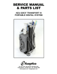
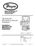
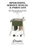
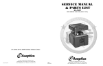
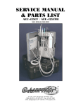
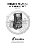
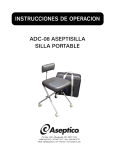
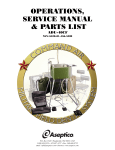
SERVICE MANUAL
& PARTS LIST
AEU-14CF EXPEDITION
EMERGENCY FIELD DENTAL UNIT
P.O. Box 1548 • Woodinville, WA 98072-1548
(800) 426-5913 • (425) 487-3157 • Fax: 425-487-2608
www.aseptico.com • [email protected]
TABLE OF CONTENTS
CONTENTS
Page
General Service Information . . . . . . . . . . . . . . . . . . . . . . . .3
Inspection & Verification . . . . . . . . . . . . . . . . . . . . . . . . . . .3
Cleaning & Lubrication . . . . . . . . . . . . . . . . . . . . . . . . . . . .4
ESD Precautions . . . . . . . . . . . . . . . . . . . . . . . . . . . . . . . . . .4
CHASSIS DISASSEMBLY
Chassis Removal . . . . . . . . . . . . . . . . . . . . . . . . . . . . . . . . . .5
Power Supply (Fig. 1) . . . . . . . . . . . . . . . . . . . . . . . . . . . . . . .5
Compressor Pump (Fig. 2) . . . . . . . . . . . . . . . . . . . . . . . . . .5
Three-Way Solenoid (Fig. 2) . . . . . . . . . . . . . . . . . . . . . . . . .5
Two-Way Solenoid (Fig. 2) . . . . . . . . . . . . . . . . . . . . . . . . . .5
Pressure Switch (Fig. 2) . . . . . . . . . . . . . . . . . . . . . . . . . . . . .5
Battery Receptacle (Fig. 3) . . . . . . . . . . . . . . . . . . . . . . . . . .6
Vehicle Battery Receptacle (Fig. 3) . . . . . . . . . . . . . . . . . . .6
Power Cord Receptacle (Fig. 3) . . . . . . . . . . . . . . . . . . . . . .6
Power On/Off Switch (Fig. 3) . . . . . . . . . . . . . . . . . . . . . . . .6
Battery Power Switch (Fig. 3) . . . . . . . . . . . . . . . . . . . . . . . .6
Foot Switch Receptacle (Fig. 3) . . . . . . . . . . . . . . . . . . . . . .6
Motor Receptacle (Fig. 3) . . . . . . . . . . . . . . . . . . . . . . . . . . .6
Needle Valve (Fig. 4) . . . . . . . . . . . . . . . . . . . . . . . . . . . . . . .6
Check Valve (Fig. 4) . . . . . . . . . . . . . . . . . . . . . . . . . . . . . . . .6
Power Board (Fig. 4) . . . . . . . . . . . . . . . . . . . . . . . . . . . . . . .7
Display Board (Fig. 5) . . . . . . . . . . . . . . . . . . . . . . . . . . . . . .8
Overlay . . . . . . . . . . . . . . . . . . . . . . . . . . . . . . . . . . . . . . . . . .9
Fan . . . . . . . . . . . . . . . . . . . . . . . . . . . . . . . . . . . . . . . . . . . . . .9
Filter Holder (Fig. 4) . . . . . . . . . . . . . . . . . . . . . . . . . . . . . . .9
Air Reservoir Cap (Fig. 6) . . . . . . . . . . . . . . . . . . . . . . . . . .9
Water Reservoir Cap (Fig. 6) . . . . . . . . . . . . . . . . . . . . . . . .9
Water Pick-Up Tube (Fig. 6) . . . . . . . . . . . . . . . . . . . . . . . . .9
Water Filter (Fig. 6) . . . . . . . . . . . . . . . . . . . . . . . . . . . . . . . .9
Air & Water Seals (Fig. 6) . . . . . . . . . . . . . . . . . . . . . . . . . . .9
Syringe (Fig. 7) . . . . . . . . . . . . . . . . . . . . . . . . . . . . . . . . . . . .9
PARTS LISTS
Page
Figure 11 - System Components . . . . . . . . . . . . . . . . . . . . .11
Figure 12 - Chassis Front . . . . . . . . . . . . . . . . . . . . . . . . . . .12
Figure 13 - Chassis Rear . . . . . . . . . . . . . . . . . . . . . . . . . . .12
Figure 14 - Chassis Internals . . . . . . . . . . . . . . . . . . . . . . . .13
Figure 15 - Chassis Internals . . . . . . . . . . . . . . . . . . . . . . . .14
Figure 16 - Chassis Front . . . . . . . . . . . . . . . . . . . . . . . . . . .14
Figure 17 - Chassis Internals . . . . . . . . . . . . . . . . . . . . . . . .15
Figure 18 - Case & Battery Pack . . . . . . . . . . . . . . . . . . . . .15
Figure 19 - Battery Pack Assembly . . . . . . . . . . . . . . . . . . .16
TROUBLESHOOTING GUIDE . . . . . . . . . . . . . . . . . . . .17
SPECIFICATIONS . . . . . . . . . . . . . . . . . . . . . . . . . . . . . . .18
SYMBOL DEFINITIONS . . . . . . . . . . . . . . . . . . . . . . . . . .18
WARRANTY . . . . . . . . . . . . . . . . . . . . . . . . . . . . . . . . . . . . .19
NOTES . . . . . . . . . . . . . . . . . . . . . . . . . . . . . . . . . . . . . . . . .19
BATTERY PACK DISASSEMBLY
Battery Pack (Fig. 8) . . . . . . . . . . . . . . . . . . . . . . . . . . . . . .10
Battery Receptacle (Fig. 9) . . . . . . . . . . . . . . . . . . . . . . . . .10
Battery Pack Board (Fig. 10) . . . . . . . . . . . . . . . . . . . . . . .10
Page 2
P.O. Box 1548 • Woodinville, WA 98072-1548
(800) 426-5913 • (425) 487-3157 • Fax: 425-487-2608
www.aseptico.com • [email protected]
Printed In The USA
GENERAL SERVICE INFORMATION
This service and parts manual offers information and parts
lists not available in the AEU-14CF Operation and
Maintenance Instruction Manual. It will help you better
understand the operation of the AEU-14CF Expedition
Emergency Field Dental Unit, thereby reducing service time.
A Schematic Diagram Set includes part drawings and
schematic diagrams which show components in their actual
places in the unit relative to one another. A plumbing
schematic is provided with water lines indicated in blue.
Plumbing parts are called out by Aseptico part number in the
assembly drawings. Electrical schematics are provided for the
chassis and battery pack with wires color coded. Electrical
parts are called out by Aseptico part number in the assembly
drawings. Parts are listed and referenced to Figures with
callouts in the Parts List. Use the information in the Parts
List when ordering replacement parts.
Inspection & Operation Verification
To verify that the AEU-14CF unit is functioning properly,
first follow the set-up procedure in the Operation &
Maintenance manual. The system is designed to run off of
multiple power systems, so it is best to isolate systems during
diagnostics. First, plug the system into a 120V/220V power
source. The system is auto switching but the fuses should be
changed for the appropriate voltage, which is listed on the
silkscreen above the receptacle. Turn the power On/Off
switch ‘On’ and the panel should light up and the compressor
pump should fill the air and water reservoirs. If the water
reservoir is empty, the pump will take longer to charge the
system. With the compressor pump engaged, the system
should pressurize to approximately 22 PSI, as indicated on
the pressure gauge. When the compressor pump is first
initialized, a three-way valve allows for the pump not to start
against a pressure head. If the unit fails to show any pressure
on the gauge, the three-way valve is usually at fault. Inspect
the unit for air and water leaks. If the pump fails to shut off
and the pressure gauge shows some pressure, then there is a
leak present. The electronics have been coated to prevent
shock. It is possible to detect air leaks with a tube or a
stethoscope, but because of the low pressure, they are hard to
detect in this manner. It is better to use the plumbing
schematic and isolate the problem by pinching off the lines
with clamps, such as a pair of hemostats. If an air leak is not
detected on the lines or fittings, check the bottles for
tightness and the condition of the seals. To check the threeway syringe, depress the air and water buttons individually
and then both buttons together for spray. The spray will be
less than a normal dental system, due to the lower pressure of
the system. Inspect the water filter on the water pick-up tube.
The water filter requires replacement if it becomes clogged
and restricts water flow. The compressor pump has a 90 PPI
filter on the underside of the chassis that requires
replacement if it becomes clogged and restricts air flow.
To check the functions of the dental motor and unit, attach
motor and foot pedal as described in the Operations Manual.
Push the buttons marked “Fiber Optic Light” and “Water” so
that the LEDs are on. Depress the foot pedal and ensure that
handpiece light comes on (you might have to depress the
positive[+] button until light is present) and that water
comes out of the handpiece. Adjust the water flow with the
coolant adjustment knob on the unit. If light fails to come on,
first check the bulb in the motor. If bulb is okay, then work
your way back through the connectors. If water fails to come
out of the handpiece, check the two-way valve. If the motor
fails to operate, check the connector pins on the motor and
the foot pedal. If the motor fails to operate from the foot
pedal, then activate the button marked “Manual”. If the
motor comes on, the problem is in the foot pedal. Check
reverse mode by pressing the “Reverse” button, and check
the motor speed by pressing the positive[+] and negative[-]
buttons.
Remove the AC power cable and attach the vehicle battery
cable to the chassis and either a 12V or 24V battery system.
Follow the setup procedure in the Operation Manual. Turn
the battery on/off switch on and the unit should light up. If
the unit fails to light up, remove the chassis as described later
in this manual (refer to page 5) and check the 15 amp fuse
coming from the vehicle receptacle on the inside of the unit .
To check the operation from the battery packs, remove other
sources of power. Attach the battery pack cable from a
battery pack to the unit. Turn the battery on/off switch on and
the unit should light up and show the charge level of the
battery pack. If the unit fails to come on, check the
connections from the battery pack to the unit.
To check the operation of the charging system, leave the
battery pack hooked up to the unit and apply either
120V/220V or 12V/24V vehicle power to the unit. The unit
will take power from the higher source. If 120V/220V power
is applied, the power on/off switch must be turned on to
check the charging. If power is coming from 12V/24V battery,
then only the battery switch needs to be on. Press the
“Charge” button on the unit and ensure that the LED lights
up.
The above procedures describe basic inspection and
verification of the AEU-14CF system. If the unit still does
not perform as required, further diagnosis of components in
the system may require service. Use the Trouble Shooting
section as a guide to symptoms and appropriate procedures
to fix various problems.
Page 3
Cleaning and Lubrication
ESD PRECAUTIONS
When servicing the AEU-14CF Emergency Field Dental
Unit, the parts of any component disassembled should be
thoroughly cleaned and inspected before reassembly. A hot
detergent solution is an effective cleaner on all non-electrical
parts. Flush all non-electrical parts with clear, hot water.
Abrasive cleaners have the potential to damage surface
finishes and should be avoided. Any wiping should be done
with a soft lint-free cloth.
The following electrostatic controls must be used when
working on this unit:
Electrical parts should be cleaned with an appropriate
electrical parts cleaner or air.
ESD Static Controlled Area:
Areas that are designated for handling and working on
electronic sub-assemblies or their components should be
marked off with signs indicating the area where ESD
controls are to be enforced. These areas are to be kept clear
from persons that are not trained to prevent ESD damage
from occurring.
Use a silicone base lubricating grease, such as Dow Corning
No. 103 to lubricate O-rings and seals in the system. Before
performing any reassembly of parts that contain O-rings or
seals, apply a light coat of silicone grease. This will make
installation easier and prevent the O-rings or seals from
being damaged.
WATER LINES - Disinfect the water lines weekly. Prepare a
1:10 bleach solution (1 part household bleach to 10 parts
water). Remove water reservoir and discard residual water.
Replace empty water supply tank and air purge all waterlines.
Fill water supply tank with bleach solution. Run bleach
solution through all lines. Allow bleach solution to stand in
lines for 10 minutes. Remove water supply tank and discard
bleach. Flush water supply tank and all lines thoroughly with
clean water. Air purge and leave lines dry until next clinical
use.
ESD Training and Standards:
Employees handling electronic sub-assemblies and ESD
sensitive components are expected to be trained. Training
should be based on IPC-A-610 or equivalent ESD standard
ANSI/ESD-S-20-20 – Protection of Electrical and
Electronic Parts, Assemblies and Equipment.
ESD Environment:
The work area is to be free of all static generating materials,
such as plastic containers, water bottles, plastic bags, plastic
objects, such as plastic pens, heat guns (unless made for the
ESD environment).
ESD Jackets:
Clothing should be non-static generating (cotton).
Static generating clothing (e.g. wool, acrylic, nylon) must be
covered with an ESD jacket that is buttoned closed.
Optional gloves:
Nitrile gloves may be used to cover the hands when
working, but are not required.
Seating:
ESD Chairs should be used in place of static generating
chairs (e.g. modern office seating use static generating
materials).
Storage and packaging:
All circuit boards and components are to be stored on or in
static dissipative or static shielding material, throughout
shipping and storage.
ESD Wrist Strap and Mat Routine Checks:
The wrist strap should be checked daily using an ESD wrist
strap testing station. See chart below.
ESD mats should be checked at least quarterly.
Page 4
DISASSEMBLY
NOTE: This system consists of two main assemblies: the
chassis assembly and the battery packs. All operating
functions of the system are encased in the chassis and can be
operated outside of the unit case if proper precautions
against electrical shock are taken.
CHASSIS REMOVAL
Stand the unit upright, into its operating position. Remove
the water bottle. Go to the rear of the case and remove the
two upper screws with a #2 Phillips head screwdriver. Go to
the top of the unit and remove the two screws while
supporting the chassis with your hand. Remove the chassis
from the case.
Reassemble the chassis in the reverse order. Check the Orings on the screws to ensure they are not damaged. If the Orings are damaged, replace with new screws or RTV screws in
place.
POWER SUPPLY - Fig. 1
Remove the connectors to the power supply board on the
pump cover. Remove the three flat head screws from the
front of the chassis cover with a #2 Phillips head screwdriver.
Remove the pump cover/power supply subassembly from the
chassis. With the subassembly removed, disassemble the
power supply from the pump cover by removing the four nuts
and lockwashers from the four corners of the power supply
with a 3/16-inch wrench.
Reassemble power supply in the reverse order. When
replacing the pump cover on the chassis, take care that the
wires and tubes are not pinched by the chassis, and that the
wires from the motor and solenoid are in the appropriate slot
in the rear of the pump cover.
Figure 1
Remove pump cover as previously described (refer to “Power
Supply” disassembly procedure above). Disconnect tube
from pump to the valve at the valve. Remove screws from the
pump and move the pump forward. Remove tube to valve
output at the valve. Disconnect wire from the power board
and remove the two screws and washers from the valve with
a 1/16-inch Allen wrench.
Reassemble solenoid in the reverse order.
TWO-WAY SOLENOID - Fig. 2
Remove pump cover as previously described under “Power
Supply” disassembly procedure. Remove screws from the
pump and suspend the pump from the back of the chassis.
Remove the two screws and washers to the valve from the
bottom of the chassis with a 1/16-inch Allen wrench. Clip the
cable ties on the wiring harness on the chassis at the bottom
of the power board. Disconnect the connector with the two
blue wires and remove the tubes from the valve.
Reassemble solenoid in the reverse order and re-tie cables
with cable ties.
Figure 2
Air Bottle
Two
Way
Solenoid
Pump
Pressure
Switch
Three
Way
Solenoid
Access
Screw
Tubes
PRESSURE SWITCH - Fig. 2
Fuse
Holders
Pump
Cover
Power
Supply
THREE-WAY SOLENOID - Fig. 2
Connectors
Remove pump cover as previously described under “Power
Supply” disassembly procedure. Disassemble the pump as
described above under “Two-Way Solenoid”. Clip the cable ties
on the wire harness on the chassis at the bottom of the power
board. Remove the vehicle receptacle with a 1/4-inch wrench to
access the nuts and washers on the pressure sensor bracket.
Remove the nuts to the bracket with a 1/4-inch wrench.
Disconnect the tube to the pressure sensor. Remove the
pressure sensor locknut with a 7/8-inch wrench. Remove 2-pin
connector with the black and green wires from the power board.
COMPRESSOR PUMP - Fig. 2
Reassemble sensor in the reverse order.
Remove pump cover as previously described (refer to “Power
Supply” disassembly procedure above). Remove tubes from
the air filter and three-way solenoid at the components.
Remove air supply bottle and remove the two screws to the
pump from the bottom of the chassis with a 3/32-inch Allen
wrench. Remove connector from power board.
To set pressure on the pressure sensor, remove the rear access
screw with a 1/8-inch Allen wrench to expose the adjustment
setscrew within the sensor. Adjust the sensor by turning the
setscrew with a 1/8-inch Allen wrench until the pressure reads
approximately 22 PSI on the gauge (with chassis power turned
on). Turning the setscrew clockwise increases the pressure
setting; counterclockwise decreases the pressure setting.
Reassemble pump in the reverse order.
Page 5
DISASSEMBLY - Continued
BATTERY RECEPTACLE - Fig. 3
MOTOR RECEPTACLE - Fig. 3
Remove the pump cover as previously described under
“Power Supply” disassembly procedure. Remove the nuts
and washers with a 1/4-inch socket. Clip the wire ties on the
cables coming from the connector. Disconnect the terminals
from the battery on/off switch and unplug the 4-pin
connector from the power board.
Remove the pump cover as previously described under
“Power Supply” disassembly procedure. Remove the screws
holding the pump to gain access to the ground stud. Remove
the top nut on the ground stud. Disconnect the 8-pin
connector at the top of the power board. Remove the four
nuts and washers with a 1/4-inch socket.
Reassemble receptacle in the reverse order.
Reassemble receptacle in the reverse order. NOTE: If
replacing old receptacle, remove ferrite block and reinstall
onto new receptacle.
VEHICLE BATTERY RECEPTACLE - Fig. 3
Remove the pump cover as previously described under
“Power Supply” disassembly procedure. Remove the nuts
and washers with a 1/4-inch wrench. Clip the cable ties and
remove the terminals to the battery switch and the 2-pin
connector to the power board.
Reassemble receptacle in the reverse order.
POWER CORD RECEPTACLE - Fig. 3
Remove the pump cover and pump as previously described
under “Power Supply” and “Compressor Pump” disassembly
procedures. Clip the cable ties on the wire harness at the
bottom of the power board.
Remove all nuts on the ground stud with a 5/16-inch wrench.
(The ground wire from the receptacle is the bottom wire.)
Remove the two flat-head screws in the front of the
receptacle with a #2 Phillips screwdriver. Remove the
terminals from the power on/off switch and remove assembly
from the chassis.
NEEDLE VALVE - Fig. 4
Remove pump cover as previously described under “Power
Supply” disassembly procedure. Remove screws from the
three-way and two-way valves. Remove the screws from the
filter holder and move out of the way to access the needle
valve. Remove the tubing from the needle valve. Remove the
knob from the front of the needle valve with a 1/16” Allen
wrench. Remove the needle valve with two 9/16-inch
wrenches. NOTE: It is recommended that a thin-walled
wrench be used on the inside nut.
Reassemble the needle valve in the reverse order.
Figure 3
Battery
Receptacle
Footswitch
Receptable
Vehicle
Battery
Receptacle
Reassemble receptacle in the reverse order.
POWER ON/OFF SWITCH - Fig. 3
Remove the two flat head screws from the power receptacle
and pull the receptacle forward. Remove the terminals from
the power switch and push the switch to the front of the
chassis.
Reassemble switch in the reverse order.
BATTERY POWER SWITCH - Fig. 3
Remove the pump cover as previously described under
“Power Supply” disassembly procedure. Disconnect the
terminals going to the switch and push the switch forward.
Reassemble switch in the reverse order.
FOOT SWITCH RECEPTACLE - Fig. 3
Remove the two screws holding the power cord receptacle
and pull the receptacle forward. Push the power switch
forward. Remove the pump cover as previously described
under “Power Supply” disassembly procedure and loosen the
pump to gain access to the ground stud. Remove the top
ground nut and clip the wire ties on the cable harness.
Remove the switch with a 3/4-inch wrench.
Reassemble receptacle in the reverse order.
Page 6
Power Cord
Receptacle
Power Switch
Coolant
Adjustment
Motor
Battery
Switch Receptacle
CHECK VALVE - Fig. 4
Remove the pump cover as previously described under
“Power Supply” disassembly procedure. Remove the screws
from the pump and swing the pump out of the way.
Disconnect the tubes to the check valve.
Reassemble valve in the reverse order. NOTE: the flow arrow
on the valve must be pointing toward the water bottle cap.
POWER BOARD - Fig. 4
Remove the pump cover as previously described under
“Power Supply” disassembly procedure. Remove the two
screws that hold the power cord receptacle and pull the
receptacle forward. Use a 3/32-inch Allen wrench to remove
the screw that attaches the two insulators and the diode
heatsink bracket. Remove bracket. Use a 1/16-inch Allen
wrench to remove the mounting screw for the trans heatsink
bracket, then remove bracket. Remove the heatsink clamp
mounting screw and standoff with a 1/16-inch Allen wrench.
Remove heatsink clamp. Remove the two mounting screws
for the heatsink clamping bracket with a 1/16-inch Allen
wrench, then remove bracket. (NOTE: It isn’t necessary to
remove the hold-down screw and locking nut mounted on the
top of the heatsink clamping bracket.) Remove the upper
heatsink bracket located on top of the power board IC chip.
Remove the two nylon standoffs from the power board.
Remove all wire and cable connectors to the power board.
Remove the remaining two nuts and washers with a 1/4-inch
socket. Lift the board off the studs to expose the ribbon cable
on the back side of the power board. Remove the thermo pad
and lower heat sink bracket from the bottom side of the
power board. Remove the ribbon cable at the power board.
NOTE: The cable connector has been sealed at the factory
with RTV - remove the RTV from cable.
To replace power board with a new board, set the new board
90° to mounting position in the unit and insert the ribbon
cable into the socket. The socket requires that both sides of
the connector lock be pushed closed at the same time. Ensure
that the cable and connector are properly aligned and seated
to each other. It is recommended to seal the ribbon cable to
the connector with RTV and allow to dry, to prevent
condensation shorts on the connector. NOTE: If RTV is not
available, use a piece of electrical tape to seal the connector
and prevent movement of the cable when reassembling.
Realign the power board to its proper mounting position and
install back in the chassis.
Reassemble power board in the reverse order. Apply thermo
compound to all heatsinks and heatsink brackets per
instructions provided on Assembly Drawing 420541, sheets 13
thru 19. Ensure there is no continuity between the upper and
lower heatsinks.
Figure 4
Motor Conn.
Foot Pedal
Conn.
Pressure Switch
Conn.
2-Way Solenoid Conn.
Pump Conn.
3-Way Solenoid Conn.
Filter
Holder
Needle
Valve
Check
Valve
Heatsink
Clamp
Heatsink
Diode
Bracket
Lower
Heatsink
Bracket
Hold-Down
Screw &
Upper Heatsink
Heatsink
Locking Nut
Bracket
Clamping Bracket
Power
Board
Page 7
DISPLAY BOARD - Fig. 5
Remove the pump cover as previously described under
“Power Supply” disassembly procedure. Remove all the
components to the power board as previously described
under “Power Board”, with the exception of the ribbon cable.
Remove the ribbon cable from the display board and clean
the RTV from the cable. Remove the two clamping bars with
a 1/4-inch thin-walled socket. Remove the board from the
chassis. To replace the board, ensure that the insulator is still
in the pocket of the chassis and install the board using the
two clamping bars. Insert the ribbon cable into the display
board and ensure that the cable is oriented and seated
properly in the connector. The socket requires that both sides
of the connector be pushed closed at the same time. It is
recommended that the ribbon cable be sealed to the
connector with RTV and allowed to dry, to prevent
condensation from shorting out the connector. NOTE: If
RTV is not available, use a piece of electrical tape to seal the
connector and prevent cable movement when reassembling
the power board.
Finish reassembling the power board in the reverse order.
Figure 5
Display
Board
Ribbon
Cable
Power
Board
Cable Connectors
Page 8
OVERLAY
The chassis does not have to be removed to replace the
overlay. Peel a corner of the overlay away from the chassis
console with an exacto knife or sharp-edged tool and pull the
overlay off the console.
To replace the overlay, align the new overlay with the console
LEDs and press into position using hand pressure. NOTE: To
help realign the overlay into position, it is recommended that
a battery pack be connected to the console and all the LEDs
turned on.
FAN & FAN GUARD - Fig. 16
Remove the pump cover as previously described under
“Power Supply” disassembly procedure. Using a #2 Phillips
head screwdriver and 1/4-inch wrench, remove the four
screws which hold the fan guard and fan to the chassis.
Reassemble fan and guard in the reverse order.
FILTER HOLDER - Fig. 4
Remove the pump cover as previously described under
“Power Supply” disassembly procedure. Disconnect the
connector from the Power Board at ‘J13’. Remove the tube
from the pump to the filter holder. Remove the air bottle to
access the filter holder mounting screws and washers.
Remove the #6 washers and screws with a 5/64-inch Allen
wrench. Clean or replace existing filter if dirty.
Reassemble holder in the reverse order.
AIR RESERVOIR CAP - Fig.6
Remove the air bottle. Remove the two flat head screws with
a 1/8-inch Allen wrench. Pull down the cap and remove the
two tubes coming from the chassis. Remove the seal and
fitting and replace in the new cap.
WATER RESERVOIR CAP - Fig. 6
Remove the pump cover as previously described under
“Power Supply” disassembly procedure. Disconnect the
pressure gauge tubing at the 4-way connector. Remove the
pressure gauge. Disconnect the two tubes in the rear of the
cap. Remove the two screws holding the cap with a 1/8-inch
Allen wrench. Remove the seal and fittings from the old cap
and install onto new cap.
Reassemble cap in the reverse order.
WATER PICK-UP TUBE - Fig. 6
Remove the water bottle. Gently pry and slide tube clamps
away from fittings at the filter and the cap. Remove tube.
Replace tube with existing filter and clamps installed.
WATER FILTER - Fig. 6
Remove the water bottle. Gently pry and slide tube clamps
away from the filter. Remove the filter and clean or replace
if clogged. Use existing fitting when installing new filter.
AIR & WATER SEALS - Fig.6
Remove the appropriate bottle. Lift out the seal from the
cap and replace with a new seal. Ensure that seal is properly
seated in the cap.
SYRINGE - Fig. 7
Unscrew the handle from the syringe head. Remove the
tubes from the syringe head. Remove the tube clamps from
the tube and remove the handle.
Reassemble syringe by placing the tube through the handle
and placing the tube clamps on the tube. Place the tube
with the line on the inner side of the tube to the water side.
Attach the handle to the syringe head and test for air, water
and spray.
Figure 7
Reassemble cap in the reverse order.
Figure 6
Air Reservoir
Cap
Cap
Seals
Handle
Syringe
Head
Tube
Clamps
Water Reservoir
Cap
Water
Filter
Tube
Clamp
Water
Pick-Up Tube
Page 9
DISASSEMBLY - Continued
BATTERY PACK DISASSEMBLY
• SOLAR PANEL RECEPTACLE - Fig.9
• BATTERY PACK - Fig. 8
Remove the four thumbscrews from the hold-down
brackets. Remove the hold-down brackets from the battery
cage. Slide the battery pack to the left and out to remove
the pack from the battery cage.
Figure 8
Remove top cover as previously described under “Battery
Receptacle” disassembly procedure. Remove battery pack
connector from the battery pack board. If solar panel
receptacle needs to be replaced, cut locking clips off the
sides of the receptacle and push receptacle to the interior
of the chassis. Replace with new receptacle.
Reassemble receptacle in the reverse order.
Thumb
Screws
Hold-Down Brackets
•BATTERY RECEPTACLE - Fig. 9
Using a #2 Phillips screwdriver, remove the top cover of
the battery pack by removing the single screw in the center
of the top cover, the four upper corner screws in the front
and back sides of the pack, and the four bottom screws on
the left and right sides of the pack. Pull the top from the
battery pack. Disconnect the connector that leads from the
battery pack receptacle to the battery pack board. Remove
the receptacle with a #2 Phillips head screwdriver and a
1/4-inch wrench.
• BATTERY PACK BOARD - Fig. 10
Remove top cover as previously described under “Battery
Receptacle” disassembly procedure. Remove center screw
in the bottom of the case with a #2 Phillips screwdriver and
remove center standoff. Disconnect all connectors to the
battery board. Remove the battery pack from the chassis. If
battery pack is to be discarded, remove and save standoff
sleeve for use later. Remove four screws holding the board
to the chassis. Lift battery pack up and to the side to clear
the side bar and keyhole slot bosses.
Reassemble board in the reverse order. NOTE: Ensure
that sleeve has been placed on the center post of the
standoff.
Figure 10
Standoff
Sleeve
Battery
Pack
Board
Reassemble receptacle in the reverse order.
Figure 9
Solar Panel
Receptacle
Battery
Pack
Receptacle
Top
Cover
Page 10
Battery Pack
Battery Pack
Connector
PARTS LIST - Figure 11 - System Contents
ITEM
PART NO
1 Final Assy, AEU-14 Expedition
2 Chassis, AEU-14 Base Cmpl
3 M/S Stnls PhdPhl 6-32 x 3/8 Self Sealing
4 Chassis, AEU-14 Cage Battr Cmpl
5 Motor/Cable Assy w/Light & Water
6 HPCE 1:1 Strt Low Speed Doriot
7 HPCE 1:5 Contra Increaser w/Fiberoptics w/water
8 Syringe, 3-Way Air Water
QTY
120295
461176-08
510604
461175-08
AE-200-30
AHP-101
AHP-72MBFO-XL
TA-90D
ITEM
8
PART NO
9 Footswitch, On/Off 8-Pin
1
1
4
1
1
1
1
1
10 Cable Assy, Battery Pack AEU-14
11 Cable Battery Assy AEU-14
12 Linecord Remote US 10Ft Gry
13 Bottle, 16oz. Pet
14 Manual, AEU-14CF Operation
15 Manual, AEU-14CF Service
16 Case, AEU-14 Expedition
1
QTY
AE-7P
330394
875043
840001
730427
420382
420417
410157
1
1
1
1
2
2
1
1
2
13
3
Figure 11
16
13
4
14 15
12
5
9
6
7
10
11
Page 11
PARTS LIST - Figure 12 - Chassis Front
ITEM
1
2
3
4
5
6
7
8
9
10
11
12
13
14
15
16
PART NO
Label, Mylar AEU-425 AIR
Bottle, 16oz Pet
Lid, Ported For NWS-8 Bottle
C/S BtnSoc Stnls 10-32 x 3/4
Guage, 0-60PSI 1/8Mpt 1” Face
Gasket, Nylon #10
Ftn Barb 10-32 x 1/16 Plated
Holder, AEU-14 Motor/Syringe
C/S BtnSoc Stnls 8-32 x 3/8
Washer, Int Star S/S #8
Overlay, AEU-14
Wire Assy, Motor Conn
M/S Stnls FlaPhl 4-40x3/8
Washer, Flat Stnls #4
Nut, Nyloc 4-40 Stnls Hex
Switch, Rocker DC On/Off
QTY
420299
730427
730472
510423
730304
730074
730062
461193
510404
510420
420370
875060
510112
510192
510394
830120
ITEM
PART NO
17 Switch, Rocker Dpst Blk/Wht
1
2
2
2
1
1
1
1
2
2
1
1
6
4
4
1
18
19
20
21
22
23
24
25
26
27
28
29
30
31
32
830018
Power Inlet w/Fuse Holder 2Amp
840081
Fuse, 5x20mm Slo-Blo 1.25A
830126
Conn DC Filtr 1-20 Amps 80 VDC with DC Inlet Conn 860156
Nut, Hex 4-40 Stnls
510434
Washer, Split Stnls #4
510433
Conn Recpt Wall-Mntg 8Pin
860165
Wire Set AEU-14 Foot Pedal Con
875042
Knob Gry Plastic 1/4D Style II
850012
Valve, Needle Control w/o Knob
730066
Guard, Fan
540011
Holder AEU-14 Filter
461180
Filter AEU-425 Air Inlet
461028
M/S Stnls PhdPhl 6-32 x 3/8
510406
Washer, Int Star S/S #6
510419
M/S FlaPhl Stnls 4-40 x 1-1/4
510621
QTY
2
1
2
1
2
2
1
1
1
1
1
1
1
2
2
1
17
16
Figure 12
11
5 6 7
18
8 9 10
13
12 14 15
3 4
19
20 21 22
23 21 22 14
2
24
1
30
28
27
31
29
32
26
25
PARTS LIST - Figure 13 - Chassis Rear
ITEM
PART NO
1 Cover, Pump AEU-14CF
2 Screw, Stnls Flaphl 4-40x3/8
3 Fuse, 5 Amp 250V
4 Fuse, 12 Amp 250V
5 Power Supply, 48VDC 2.3A Medica Grade
461177
510112
830110
830084
730525
QTY
1
1
1
1
1
ITEM
PART NO
6 Nut, Hex 4-40 Sml Ptn Pltd
510005
510022
461199
461357
730427
830064
7 Spacer, Nyl 1/4Rndx.210Lx.14ID
8 Insulator, AEU-14 Power Board
9 Shield, Power Board AEU-14CF
10 Bottle, 16oz. Pet
11 Fuse Block, 12 Pole
10
2
2
11
1
8 9
3
7
6
4
4
5
Page 12
Figure 13
QTY
4
9
1
1
2
0.167
PARTS LIST - Figure 14 - Chassis Internals
ITEM
1
2
3
4
5
6
7
8
9
10
11
12
13
14
15
16
17
18
19
20
21
PART NO
PCB Assy, AEU-14 Pump Motor
Insulator, AEU-14 Pump Motor
Pump, Oiless Diaphragm 24VDC .4A
Motor Brkt Mount 9/16x1/2
C/S Btnsoc Stnls 8-32 x 3/8
Washer, Int Star S/S #8
Valve, 3 Way Solenoid 24V
C/S Btnsoc Stnls 4-40x1/4
Washer, Split Stnls #4
Ftn Barb 10-32 x 1/8 90D Elbow
Ftn Barb 10-32 x 1/8 Brt/Nkl
Gasket, Nylon #10
Holder, AEU-14 Filter
M/S Stnls Phdphl 6-32 x 3/8
Washer, Int Star S/S #6
Valve, 2 Way Normally Closed
Ftn Elbow 90 10-32 x 1/16 Barb White Nylon
Conn Recpt Wall-Mntg 8Pin
Nut, Hex 4-40 Stnls
Washer, Flat Stnls #4
Conn DC Filtr 1-20 Amps 80 VDC with DC Inlet Conn
ITEM
QTY
330383
461288
730490
730413
510404
510420
730474
510016
510433
730023
730073
730074
461180
510406
510419
730469
730011
860165
510434
510192
860156
PART NO
22 Switch Pressure 10-100 Modifid AEU-425
1
1
1
2
4
6
1
2
2
1
1
2
1
2
2
1
4
1
34
41
1
460905
730430
461282
510610
461650
510031
510547
461651
490007
461335
510206
461649
461652
330364
510127
510022
461359
510620
461336
850010
461280
510671
23 Nut, Lock 1/4 NPSL
24 Brkt AEU-14 Pressure Switch
25 C/S SocHd Stnls 4-40 x 5/8
26 Bracket Heat Sink Clamping AEU-14CF
27 C/S BtnSoc Blk 4-40 X 3/8
28 Standoff Nylon 4-40 X 1/2 L X 1/4 Hex
29 Bracket Heat Sink Upper AEU-14CF
30 Thermo Heatsink Compound
31 Clamp AEU-14 Heatsink
32 Tie Wrap Mount 3/4 X 3/4 w/Adh Back
33 Pad Driver Chip AEU-14CF
34 Bracket Heat Sink Lower AEU-14CF
35 PCB Assy AEU-14 Power
36 Washer, Flat Nylon .120IDx.250ODx.032T
37 Spacer, Nyl 1/4Rndx.210Lx.14ID
38 Brkt AEU-14CF Heat Sink Diode
39 M/S RndSlt Nylon 4-40 x 1/4
40 Brkt AEU-14 Trans Heatsink
41 Insulator, Mica to-220
42 Brkt AEU-14 Shield Left
43 M/S Phpl Stnls #4-40 x 3/8
13
16
18
11
8
10
14
17
8
19
12
9
12
15
12
9
20
4
7
5
6
3
QTY
1
1
1
1
1
2
3
1
1
1
1
1
1
1
28
9
1
1
1
1
1
2
Figure 14
24 43 9
21 19 9
22 23
11 12
1
2
40 8
35 19 36 37
9
38 39 41
42
19
25
26
27
8
28
31
28
34
33
40
8
9
37
38
39
30
29
34
41
42
Page 13
PARTS LIST - Figure 15 - Chassis Internals
ITEM
1
2
3
4
5
6
7
PART NO
Valve, Check Anti Retraction
Sleeve Clamp Ftn 1/8ID Clear
Ftn 10-32 Cross 4Port Fem
Ftn Barb 10-32 x 1/16 Plated
Gasket, Nylon #10
Ferrite EMI Suppression Core
Wire Assy, Motor Conn
730012
730015
730141
730062
730074
870267
875060
QTY
1
6
1
4
4
2
1
ITEM
8 Switch, Rocker DC On/Off
9 Washer, Split Stnls #4
10 Washer, Flat Stnls #4
11 Nut, Hex Stnls 4-40
12 Switch, Rocker Power On/Off
13 Knob, Gry Plastic 1/4ID Style II
14 Valve, Needle Control w/o Knob
PART NO
QTY
830120
510433
510192
510434
830018
850012
730066
1
4
4
4
1
1
1
Figure 15
7 9 10 11
6
13 14 4
1 2
12
3
4 5 2
8
PARTS LIST - Figure 16 - Chassis Front
ITEM
1
2
3
4
5
6
7
8
9
10
11
12
13
14
15
PART NO
Power Inlet w/Fuse Holder 2Amp 2 Pole Line Filtered 840081
Fuse 5x20mm Slo-Blo 1.25A
830126
M/S Stnls FlaPhl 4-40 x 3/8
510112
Conn DC Filtr 1-20 Amps 80 VDC
860156
Nut, Hex 4-40 Stnls
510434
Washer, Split Stnls #4
510433
Guard, Fan
540011
M/S FlaPhl Stnls 4-40 x 1-1/4
510621
Fan, 12 VDC 70mA 8.0 CFM
540010
Conn Recpt Wall-Mntg 8Pin
860165
Washer, Flat Stnls #4
510192
Holder AEU-14 Filter
461180
Filter, AEU-425 Air Inlet
461028
M/S Stnls Phdphl 6-32 x 3/8
510406
Washer, Int Star S/S #6
510419
QTY
1
2
2
1
6
6
1
4
1
1
4
1
1
2
2
ITEM
PART NO
16 Ftn Barb 10-32 x 1/16 Plated
730062
730023
730074
730473
461523
510476
510423
AA-95B
730326
730073
461179-08
510404
510420
461193
730304
461458
17 Ftn Barb 10x32 x 1/8 90D Elbow
18 Gasket, Nylon #10
19 Gasket For NWS-8 Bottle Lid
20 Cap, Water Bottle AEU-14
21 C/S FlaSoc Stnls 10-32x1/2
22 C/S BtnSoc Stnls 10-32 x 3/4
23 Tubing, Poly 1/4OD Blu
24 Filter 10-32 Thread Stainless
25 Ftn Barb 10-32 x 1/8 Brt/Nkl
26 Brkt AEU-14CF Cap Cmpl
27 C/S BtnSoc Stnls 8-32 x 3/8
28 Washer, Int Star S/S #8
29 Holder AEU-14 Motor/Syringe
30 Guage 0-60PSI 1/8Mpt 1” Face
31 Cap, Air Bottle AEU-14
Figure 16
31 21 16 17 18
19
10 5 6 11
8 9
7 9
4 5 6
26 27 28
12 13 14 15
16 18
19
23 24 25
1
2
3
25 18
20 22
29 27 28 30 18 16
Page 14
QTY
1
1
4
2
1
2
2
1
1
2
1
4
4
1
1
1
PARTS LIST - Figure 17 - Chassis Internals
ITEM
PART NO
1 Cable Jumper 30 Pin 6Inch 1mm
870271
461283
510434
510433
510192
2 Clamp, AEU-14 Display
3 Nut, Hex 4-40 Stnls
4 Washer, Split Stnls #4
5 Washer, Flat Stnls #4
QTY
1
2
6
6
6
ITEM
PART NO
6 PCB Assy AEU-14 Display
330391
461284
830018
830120
461293
7 Insulator, AEU-14 Display Board
8 Switch, Rocker Power On/Off
9 Switch, Rocker DC On/Off
10 Insulator, AEU-14 Power Switchs
QTY
1
1
1
1
1
Figure 17
9
8
10
6
7
1
3 4 5
2
PARTS LIST - Figure 18 - Case & Battery Pack
ITEM
1
2
3
4
5
6
PART NO
Case AEU-14 Expedition
(Not Shown) Foot, Case AEU-14
M/S Stnls PhdPhl 6-32x3/8 Self Sealing
(Not Shown) Label AEU-14CF Repackaging
Chassis AEU-14 Cage Battr Cmpl
M/S Stnls PhdPhl 6-32x3/4 Self Sealing
410157
461290
510561
420460
461175-08
510589
QTY
1
2
4
1
1
2
ITEM
7 Brkt AEU-14 Battery Cage Cmpl
8 Thumbscrew Stnl 4-40x5/16L
9 Hold-Down Bracket
10 Battery Pack Assy AEU-14
11 M/S PnHd Ph SS 6-32 x 1/4 Sealing
PART NO
461178-08
510245
461459-08
330365
510605
QTY
1
4
1
2
2
Figure 18
1 4
10
5 6 3
9
7
8
2 3 11
Page 15
PARTS LIST - Figure 19 - Battery Pack Assembly
ITEM
1
2
3
4
5
6
7
8
9
PART NO
Battery Pack Assy AEU-14
Chassis AEU-14 Battery Top
M/S Stnls FlaPhl 4-40x3/8 Flat Undercut
Bar, AEU-14 Battery Pack Clamping
Chassis AEU-14 Batry Base Cmpl
Conn Recpt Wall-Mntg 8Pin
Nut, Nyloc 4-40 Stnls Hex
Washer, Flat Stnls #4
Conn Crimp Socket 14AWG
330365
461194
510112
461188
461195-08
860165
510394
510192
860163
QTY
1
1
34
4
1
1
4
4
2
ITEM
PART NO
10 Conn Crimp Socket 22-20AWG
11 Conn Hsng 2 Pin In-Line Recept
12 Conn Crimp Socket 20-14 AWG
13 Standoff AEU-14CF Battery Case
14 Tubing Silicone .281IDx.375OD 70 Duro Gray
15 Battery Pack AEU-14CF 27.6V 2600mA-h Ni-CD
16 Pad, AEU-14CF Battery Heatsink
17 PCB Assy AEU-14 Temperature
860169
860114
860111
461333
730489
820042
461334
330392
13
3
15
14
Figure 19
1
11 12
3 7 8
6 9 10
5
2
17
4 3
16
4 3
3
Page 16
QTY
2
1
2
1
1
1
1
1
TROUBLESHOOTING GUIDE
PROBLEM
CORRECTION
Chassis does not light when turned on:
Check chassis to power connection.
Check that voltage is proper voltage.
Check fuse. If blown, replace with 1.25A/250V slo-blo fuse for 120V operation, & 0.6A/250V
slo-blo fuse for 230V operation.
Chassis lights when turned on, but handpiece does not turn:
Check motor plug connection.
Check foot switch connection.
Depress foot switch.
Increase RPM.
Check that an instrument is properly seated in the handpiece and the collet is closed.
Chassis does not light when 12V/24V power is applied:
Check 12A fuse inside chassis (blue fuse wired to the vehicle battery connector).
Chassis does not light when battery pack is applied:
Check connections at the battery pack, chassis, and cable.
Check voltage of the battery pack
Check the 5A fuse inside the chassis (amber fuse wired to the battery pack connector).
Motor slowing down or sluggish:
Dirty, under-lubricated handpiece.
Handpiece lubricant is running into motor.
After lubricating, set handpiece with head down to let excess lubricant drain out.
Pressure fails to stabilize:
Check that air and water bottles are tight. Check line and fittings for air leaks.
Pressure fails to turn off at approximately 20 PSI:
Check for broken cable to pressure switch.
Check pressure settings.
Unit fails to build pressure:
Check that bottles are tight. Check wires for breaks to solenoid switch.
Battery fault light on:
Battery not connected, or charging error observed. Allow battery pack to cool to below 35°C
for 30 minutes before attempting charge. If battery fault light is on for two consecutive
charging attempts, replace battery pack.
Unit fault light on:
Unit operational error observed. Remove all power from unit for 30 minutes before
attempting to use the system again. If unit fault light is on during two consecutive attempts to
operate the system, return system for repair.
AC / DC Source lights flash On/Off:
Unit operational error. Return system for repair.
Page 17
SPECIFICATIONS
SYMBOL DEFINITIONS:
Size: . . . . . . . . . . . . . . . . . . . . . . . . . .17.5” x 11.6” x 6.9”
(44.5 cm x 29.5 cm x
17.5 cm)
Type B Equipment
Volume: . . . . . . . . . . . . . . . . . . . . . . .0.81 ft3 (0.23 m3)
Attention, consult
accompanying documents
Weight: . . . . . . . . . . . . . . . . . . . . . . .27 lbs
(12.25 kg)
Power Source: . . . . . . . . . . . . . . . . . .AC Dual Voltage
120V/230V @ 50Hz/60Hz
12V/24V vehicle battery
27.6V battery pack (x 2)
Dangerous Voltage
Do Not Throw Into Trash
Water Reservoir Capacity: . . . . . . . .16 fl. oz. (0.423 liter)
Air Reserve Capacity, Standard: . . .25.8 in3 (423 cc)
Noise Levels . . . . . . . . . . . . . . . . . . .64 dBa @ 1 meter (3’4”)
Alternating current
Fuses: . . . . . . . . . . . . . . . . . . . . . . . .120V: 1.25A, 250V slo-blo fuse
(Installed at factory)
230V: 0.6A, 250V slo-blo fuse
Protective earth (ground)
Fuse Size: . . . . . . . . . . . . . . . . . . . . .5 x 20mm
Duty Cycle for AE-200-30 Motor: . .Intermittent use:
1 minute On /
3 minutes Off
Mains Current Ratings: . . . . . . . . . .120V: 1.25A, 230V: 0.6A
NOTE: The appliance inlet is the mains disconnect means.
Environmental Conditions:
- Operating Temperature: 2° to 49° C (35° to 120° F)
- Transport/Storage Temperature: -20° to 60° C (-4° to 140° F)
- Relative Humidity: 5 to 95% non-condensing
- Altitude: 0 to 2591 meters (0 to 8,500 feet)
NOTE: Air pressure instruments are set to 2591 meters (8,500 ft) elevation.
WARNING: Equipment not suitable for use in the presence of a
flammable anaesthetic mixture with air, or with oxygen or nitrous
oxide.
CAUTION: If the integrity of the protective earth ground is in doubt,
only use battery pack or vehicle battery power for operation.
MEDICAL EQUIPMENT WITH RESPECT
TO ELECTRIC SHOCK, FIRE AND
MECHANICAL HAZARDS ONLY IN
ACCORDANCE WITH UL 2601-1
CAN/CSA C22.2 No. 601.1
• Type of Protection Against Electric Shock:
- Class I when system is powered by mains power source.
- Class II when system is powered by Vehicle Battery
power source.
- Internally Powered Equipment for Battery Pack
power source.
• Degree of Protection Against Electric Shock: Type B Applied Part
• Degree of Protection Against Ingress of Water: Ordinary Equipment
• Mode of Operation: Continuous
This device has been tested and found to comply with the emissions requirements of IEC
60601-1-2:2001-09. These requirements provide reasonable protection against harmful
electromagnetic interference in a typical medical installation. However, high levels of radiofrequency (RF) emissions from electrical devices, such as cellular phones, may disrupt the
performance of this device. To mitigate disruptive electromagnetic interference, position this
device away from RF transmitters and other sources of electromagnetic energy.
Page 18
IPX1
Protect Against Dripping Water
WARRANTY
Aseptico warrants this product against defects in material or workmanship for a period of two (2) years, from date of
original invoice. Some handpieces are warranted for one year under the same conditions. Other handpieces and
expendable components, such as air turbines and light bulbs, are covered by shorter warranty periods, or have no warranty.
Aseptico's sole obligation under product warranty is (at its sole option and discretion) to repair or replace any defective
component or product in part or whole. Aseptico shall be the sole arbiter of such action.
In the event of alleged defect under warranty, the purchaser is to notify Aseptico's Customer Service Department promptly.
Customer Service will provide instructions, usually directing that the product be returned for service. Shipment to Aseptico
and the cost thereof is always the responsibility of the purchaser.
Accidental misuse, inappropriate installation, or failure to perform directed maintenance voids the warranty. Deliberately
defacing, modifying, or removing the serial number voids the warranty.
Aseptico does not assume, under this warranty, any risks or liabilities arising from the clinical use of its products, whether or
not such use involves coincidental utilization of products manufactured by others.
REPAIRS
Aseptico repairs carry a ninety (90) day limited warranty against defects in material and workmanship. This warranty
pertains only to the specific repair. Any new and different defect in materials or workmanship will be treated as a new
repair. If the product is not covered under warranty, Aseptico offers Repair Services for a fee.
NOTES
Page 19
For Further Service And/Or Technical Assistance Contact:
P.O. Box 1548 • Woodinville, WA 98072-1548
(800) 426-5913 • (425) 487-3157 • Fax: 425-487-2608
www.aseptico.com • [email protected]
P/N: 420417
Rev. G
ECO 13123
06/2013
PRINTED IN THE USA