1
Transearch
User’s
Manual
Revised: July 7
2011
The Transearch User’s Manual contains a comprehensive introduction to Gulfcoast
Software’s Transearch application, including an explanation of overall concepts,
enumeration of features, and quick tips for performing basic functions and
everyday procedures.
Transearch
3.4
Table of Contents
Basic Transearch Screen ..................................................................................................................................................................... 1
Registering Transearch ....................................................................................................................................................................... 2
Using Transearch ................................................................................................................................................................................ 3
Logging In and Exiting Transearch .................................................................................................................................................. 3
The Login Screen ........................................................................................................................................................................ 3
Minimizing and Exiting Transearch ............................................................................................................................................ 3
Connecting To and Viewing Video, Audio and Data ....................................................................................................................... 4
Connect to the “Local DVR” ....................................................................................................................................................... 4
“Video Only” and “Video and Data” .......................................................................................................................................... 4
Multicam .................................................................................................................................................................................... 9
Open a Backup ........................................................................................................................................................................... 9
Open a Data File ....................................................................................................................................................................... 10
Open a Video file ...................................................................................................................................................................... 10
Connect to a Remote DVR ........................................................................................................................................................ 10
Review .......................................................................................................................................................................................... 17
Searching by Video Event ......................................................................................................................................................... 17
Searching with Data ................................................................................................................................................................. 18
Advanced Data Searches .......................................................................................................................................................... 19
Searching with the Exception List (X-List) ................................................................................................................................ 21
Review Audit ............................................................................................................................................................................ 22
Playback Controls ..................................................................................................................................................................... 26
The Camera Viewing Area ........................................................................................................................................................ 26
Camera Options ....................................................................................................................................................................... 28
Audio Channels ........................................................................................................................................................................ 30
Backing Up Video, Audio and Data .......................................................................................................................................... 31
Reports ......................................................................................................................................................................................... 32
Preview a Report ...................................................................................................................................................................... 33
Email a Report .......................................................................................................................................................................... 34
Quick Print a Report ................................................................................................................................................................. 34
Save a Report ........................................................................................................................................................................... 34
Training ......................................................................................................................................................................................... 34
Reviewing the Training History ................................................................................................................................................ 35
Sending Emails .............................................................................................................................................................................. 35
Taking a Screen Shot .................................................................................................................................................................... 36
Configuring Transearch ..................................................................................................................................................................... 37
TRANSEARCH TECHNICAL MANUAL
Page ii
Enabling the On-Screen Keyboard Feature .................................................................................................................................. 37
Managing User accounts .............................................................................................................................................................. 38
System Setting .............................................................................................................................................................................. 40
Configuring Transearch and Windows Preferences ................................................................................................................. 40
Configuring Capture Devices .................................................................................................................................................... 41
Locking Transearch after User Inactivity .................................................................................................................................. 41
Configuring the Camera for the Training History ..................................................................................................................... 41
Configure Remote Review Settings .......................................................................................................................................... 41
Configuring the Backup Drive List ............................................................................................................................................ 42
Configuring the Exception List (X-List) .......................................................................................................................................... 42
Adding a Rule ........................................................................................................................................................................... 42
Editing a Rule ........................................................................................................................................................................... 43
Remove a Rule ......................................................................................................................................................................... 43
Configuring Review Audit ............................................................................................................................................................. 44
Email Settings ............................................................................................................................................................................... 45
Creating Email Groups ............................................................................................................................................................. 46
Create a New Email Contact .................................................................................................................................................... 46
Importing and Exporting Email Contacts ................................................................................................................................. 46
Email Server Settings................................................................................................................................................................ 46
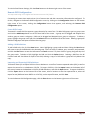
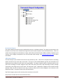
Remote DVR Configuration .......................................................................................................................................................... 47
Create DVR Groups .................................................................................................................................................................. 47
Adding a DVR Definition ........................................................................................................................................................... 47
Importing and Exporting DVR Definitions ................................................................................................................................ 47
Configuring Additional Monitors to Display Live Video ................................................................................................................ 48
Setting Coordinates .................................................................................................................................................................. 49
Choosing Which Cameras to Display ........................................................................................................................................ 49
Configuring a Camera ............................................................................................................................................................... 49
Editing the Marquee ................................................................................................................................................................ 49
Configuring Reports ...................................................................................................................................................................... 50
Transearch Reports .................................................................................................................................................................. 51
Point Of Sale Specific Reports .................................................................................................................................................. 54
Store Setup ............................................................................................................................................................................... 55
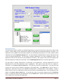
Shift Analysis Setup .................................................................................................................................................................. 55
Department Setup.................................................................................................................................................................... 57
Shift Analysis Decision Matrix Setup ........................................................................................................................................ 58
Export Report Configuration .................................................................................................................................................... 59
TRANSEARCH TECHNICAL MANUAL
Page iii
Scheduling Reports ....................................................................................................................................................................... 60
Step 1: Time Setup ................................................................................................................................................................... 60
Step 2: Output Mode ............................................................................................................................................................... 61
Step 3: Schedule Report ........................................................................................................................................................... 61
Configuring Data Capture ............................................................................................................................................................. 61
Serial Port Settings ................................................................................................................................................................... 62
Data Transport Settings ........................................................................................................................................................... 62
Advanced POS Settings ............................................................................................................................................................ 63
Automatic Date of Birth Check................................................................................................................................................. 63
Multiprint Printers ................................................................................................................................................................... 64
Common Names ....................................................................................................................................................................... 64
Transearch Settings for Point of Sale Devices .......................................................................................................................... 64
Configuring Real Time Monitoring ............................................................................................................................................... 78
Limit Datastream ...................................................................................................................................................................... 79
Schedule Time .......................................................................................................................................................................... 80
Time Frame / Time Out ............................................................................................................................................................ 81
Event Limits .............................................................................................................................................................................. 82
Select Alerts ............................................................................................................................................................................. 83
Select Criteria ........................................................................................................................................................................... 84
Creating Real Time Monitoring Alerts .......................................................................................................................................... 86
Email Alert ................................................................................................................................................................................ 86
Configuring a DVR for Remote Connections ................................................................................................................................ 87
Connecting to Video Capture Software ........................................................................................................................................ 87
Using GeoVision’s Multicam .................................................................................................................................................... 88
Using Pysoft’s Active Webcam ................................................................................................................................................. 89
Troubleshooting ................................................................................................................................................................................ 90
Getting Software Version Information ......................................................................................................................................... 90
Accessing the Users’ Manual ........................................................................................................................................................ 90
Administrator Tools ...................................................................................................................................................................... 90
The Command Prompt ............................................................................................................................................................. 91
Logs .......................................................................................................................................................................................... 91
Windows Explorer .................................................................................................................................................................... 91
Connect Drive Program ............................................................................................................................................................ 91
Keyboard Options .................................................................................................................................................................... 93
Ping .......................................................................................................................................................................................... 94
Settings..................................................................................................................................................................................... 94
TRANSEARCH TECHNICAL MANUAL
Page iv
Task Manager ........................................................................................................................................................................... 99
Defrag ....................................................................................................................................................................................... 99
GC Explorer .............................................................................................................................................................................. 99
Compact and Repair DBs .......................................................................................................................................................... 99
Get Updates from the Web ...................................................................................................................................................... 99
One-Click Online Help ................................................................................................................................................................... 99
System Status ............................................................................................................................................................................. 100
Communications Window .......................................................................................................................................................... 101
Contact Gulfcoast Software Solutions, LLC. ............................................................................................................................... 102
Reinstalling Transearch .............................................................................................................................................................. 102
PROBLEM: Video does not display in review mode ................................................................................................................... 102
PROBLEM: Video does not display in live mode or on the security monitors ............................................................................ 102
PROBLEM: Audio does not play in live mode ............................................................................................................................. 103
PROBLEM: I don’t see any Point Of Sale (POS) data ................................................................................................................... 104
Troubleshoot a serial port ...................................................................................................................................................... 104
Troubleshooting POS cable connections ................................................................................................................................ 105
Troubleshoot a POS to see if it is transmitting data .............................................................................................................. 112
PROBLEM: The Point of Sale (POS) data is garbled or has funny characters .............................................................................. 113
PROBLEM: Multicam does not display correctly ........................................................................................................................ 113
PROBLEM: The Exception List (X-List) definitions do not match my Point Of Sale (POS) type ................................................... 113
PROBLEM: Transearch does not start up or has a fatal error when it loads up ......................................................................... 113
PROBLEM: Clicking the Review button or a remote site on the Review button popup menu does nothing ............................. 114
PROBLEM: The Exception List (X-List) is all zeros ....................................................................................................................... 114
PROBLEM: I can’t connect to a remote DVR that is running Transearch ................................................................................... 114
PROBLEM: I can connect to a remote DVR but I can’t review data, video or audio................................................................... 114
PROBLEM: I am having problems running Transearch in Windows Vista or Windows 7 ........................................................... 114
PROBLEM: Video plays too quickly in Windows Media Player ................................................................................................... 114
PROBLEM: The Advanced Save Video option is not available in review mode. ......................................................................... 114
TRANSEARCH TECHNICAL MANUAL
Page v
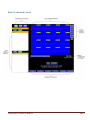
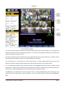
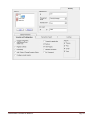
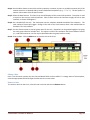
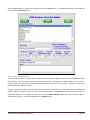
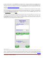
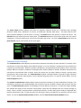
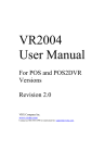
Basic Transearch Screen
TRANSEARCH TECHNICAL MANUAL
Page 1
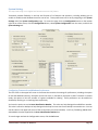
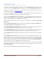
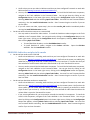
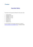
Registering Transearch
Gulfcoast Software Solutions, LLC provides a suite of loss prevention tools that must be registered for full
functionality and data integration. The software can be licensed to provide enterprise capabilities which include
enabling remote clients to dial into the software to view video, data and audio remotely. The software can also be
licensed to capture a specific number of data sources including POS data. Without a valid software license, the
enterprise servers and the data capture engine will be disabled. Note that registration is not necessary to review
backups, local files or to connect to licensed, remote DVRs.
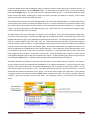
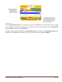
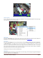
If the system is unregistered, a red “Unregistered” information box will appear below the camera viewing area in all
modes but Remote Live. To access the registration screen, click the Help button below the camera viewing area and
select the Registration option from the menu.
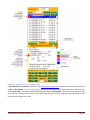
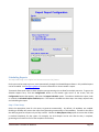
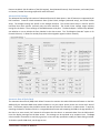
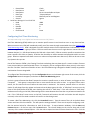
The Registration screen will display the Gulfcoast Technical Support number, software version number, licensing
specifications, serial number, and registration code. If the serial number and registration codes are blank, you are
encouraged to call Gulfcoast Software Solutions, LLC at (727) 449-2296 to register the software. A Gulfcoast
technician will prompt you to enter the appropriate information to complete the registration process.
TRANSEARCH TECHNICAL MANUAL
Page 2
Using Transearch
The basic concepts of Transearch include connecting to, reviewing, and watching video, audio, and data streams.
Transearch allows you to connect to a variety of sources including the local DVR system or a remote DVR. Once
connected, Transearch provides a dynamic live viewing experience that allows you to watch video and data, as well
as hear audio, as it is recorded in real time.
In addition to reviewing the local DVR or a remote DVR, you can review recorded video, audio and data that has
been stored on valid backup media, such as hard drives, thumb drives, CDs, and DVDs.
Logging In and Exiting Transearch
Unregistered systems do not support this feature.
Transearch provides multilevel user access. Some features requiring upper level access might include viewing a
backup, accessing remote sites, opening Admin Tools, shutting down or minimizing the software, or changing
configuration information. In general, if an item is grayed out or inaccessible, you may need to login using an
account with the appropriate permissions to access those features.
Note that account privileges can be tailored to suit the needs of the individual client and are fully modifiable by
administrator accounts. The default account that is automatically logged in when the software loads can also be set
by an administrator in the configuration section of Transearch. To configure these options, see Managing User
Accounts.
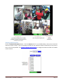
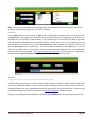
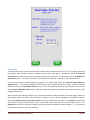
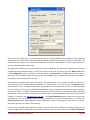
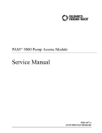
The Login Screen
To access the Login screen, click on the Configuration button in the tool bar at the bottom right hand corner of the
screen. A list of three options will appear. Click the Login button. This will bring up the Login form. Enter your
username in the Login ID box, your password in the Password box, and hit the Login button to login or the Cancel
button to cancel. If the username and password do not match an existing account, an error message will prompt
you to try again; a successful login will result in the Transearch Login form disappearing.
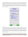
Minimizing and Exiting Transearch
You may need to log in to a higher level account to access this feature.
Click on the Configuration button in the tool bar at the bottom right corner of the screen. A list of three options will
appear. Click on the Exit button and choose either Minimize Transearch to minimize the software, or Close
Transearch to exit the application.
TRANSEARCH TECHNICAL MANUAL
Page 3
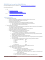
Connecting To and Viewing Video, Audio and Data
Transearch supports a multifaceted interface that allows you to connect to various combinations of video, audio and
data. This is done via the Connect button in the top left corner of the screen.
Connect to the “Local DVR”
To connect to the video, audio and data on the local DVR, click the Connect button and choose the Local DVR
option. The Local DVR can be configured to capture video, audio and data from a variety of sources. See Connecting
to Video Capture Software and Configuring data capture for instructions on how to set up Transearch to display
these sources.
Licensed systems with POS integration can display video, audio and data in real time, giving you an accurate
representation of events as they are currently happening. Or it can display a snapshot in time of events captured for
reviewing. For more information on reviewing video, audio and data, see Review.
To view video, audio and data in real time, click the Live button near the upper left corner and select one of the
three options: Video Only, Video and Data, and Multicam.
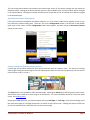
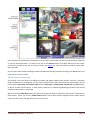
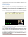
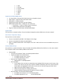
“Video Only” and “Video and Data”
Both modes can display numerous live video feeds simultaneously. Each video feed contains a camera tag which
indentifies or describes that camera.
If the system is setup to capture audio, audio controls will be visible on the far right. A drop down menu enables
you to select which channel of live audio to listen to. A vertical slider bar enables you to adjust the volume of the
live audio.
Adjusting the Camera Viewing Area in Video Only or Video and Data
The camera viewing area displays camera video in real time. Three sets of buttons allow you to navigate through
the available cameras: the camera number buttons, the camera layout buttons, and the next/previous camera
buttons.
TRANSEARCH TECHNICAL MANUAL
Page 4
The camera number buttons are located at the bottom left hand side of the camera viewing area. Clicking one will
display only the camera that corresponds to that button. For instance, clicking 1 will instantly present you with a full
screen view of the first camera in the list.
The camera layout buttons are located on the upper right hand side of the camera viewing area. Clicking a camera
layout button will arrange the cameras in the layout indicated on the button.
For an NxN layout (i.e., a layout that is as many cameras tall as it is wide), single-clicking any given camera will
display it in full-screen mode. Single-clicking the full-screen camera will return to the previous layout.
For a non-NxN layout, single-clicking a camera will select it for swapping with another camera; to swap it, simply
single-click a second camera and watch the two switch places in the layout. Double-clicking a camera will bring it to
full-screen size. Double-clicking a full-screen camera will revert to the previous layout.
The Scan button is located beneath the camera layout buttons. Clicking the Scan button will rotate through a fullscreen view of each camera with a pause in between. To turn the camera scan off, simply click the Scan button
again.
TRANSEARCH TECHNICAL MANUAL
Page 5
The next and previous buttons are located at the bottom right corner of the camera viewing area just above the
date/time stamp. Clicking the >> button will take you to the next available screen of cameras which will be arranged
in the selected layout. Clicking the << button will take you to the previous screen of cameras which will be arranged
in the selected layout.
Refreshing the Camera Viewing Area
If the camera setup has changed in the capture software, or if an IP camera’s video stream appears to lock up, you
may refresh the camera viewing area. To do this, click on the Configuration button in the tool bar on the bottom
right corner of the screen, click the Configuration button which appears, and then choose the Reconnect Cameras
option from the menu.
Saving, Printing and Emailing camera pictures
Camera tags are the labels attached to each camera view that state the camera’s name. If a camera is receiving
video, single-clicking the camera tags in Live view will bring up a shortcut menu with the options to print the current
camera frame, email it, or save it.
The Email option is only available in Video and Data mode. Selecting the Email option will bring up the email screen,
which allows you to send the current image as an attachment. For more information about the Transearch Email
screen, see Sending Emails.
Selecting the Print option lets you choose between printing a Half Page or a Full Page. (Note that a half page prints
the exact same image as a full page except that it is smaller to help conserve ink.) A dialog then opens to allow you
to select an available printer from which to print the current image.
TRANSEARCH TECHNICAL MANUAL
Page 6
Selecting the Save option allows you to save the selected image. A dialog box appears that allows you to select
where to save the image. After naming the image and selecting the preferred image format, click the Save button.
“Video and Data” Specific Features
Video and Data mode displays both the live cameras and the live data side by side. You can change which data
stream to watch by clicking on either of the Register buttons above their corresponding data displays. You can then
select from the popup menu the data stream you wish to assign to that data stream display.
Clicking on the Review button above a data stream display will take you to the review screen and display the most
recent data captured for that register. See Search with Data for more information.
TRANSEARCH TECHNICAL MANUAL
Page 7
“Video Only” Specific Features
Video Only mode does not show data, but rather offers a full screen view of the cameras. To exit Video Only mode,
click the Exit button. If a password is required to exit, type in the password and hit the Enter key. See Setting the
Video Only Password for more information.
The Video Only screen can also be configured to act as a screen saver after the user-specified number of minutes of
inactivity have elapsed. See Locking Transearch after User Inactivity for further information.
TRANSEARCH TECHNICAL MANUAL
Page 8
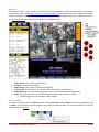
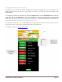
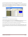
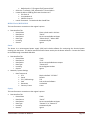
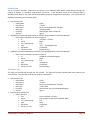
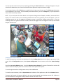
Multicam
The Multicam option is only available if Transearch has been configured to read video and audio from GeoVision
brand capture cards. See Setting Transearch to work with Multicam for further instructions. If Multicam has been
properly configured, this mode will display Multicam’s live video screen and give you access to Multicam’s menus.
See Viewing Multicam for a description of Multicam’s available features.
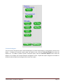
1.
2.
3.
4.
5.
6.
Video Record: Start / Stop recording video
Schedule: Sets up video schedule.
Video Config: Quick access to video and audio setup.
Camera Scan: Click the button to start the rotation through the screen division.
Network Servers: Click the button and enable connection for different remote applications.
Login: Brings up several options, including Login/Exchange, Logout, Minimize and Exit.
Must be logged in as a supervisor to make changes.
Open a Backup
To connect to a backup, click the Connect button, choose Local Files, select Archive, browse to the backup file, and
click Open. You may then review the backup as you would any video and data. For more information on reviewing
video and data, see Review.
TRANSEARCH TECHNICAL MANUAL
Page 9
Open a Data File
To open a data file, click the Connect button, choose Local Files, select Data, browse to the data file you wish to
view, and click Open. For more information on reviewing the data, see Review.
Open a Video file
To open a video file, click the Connect button, choose Local Files, select Video, browse to the video file you wish to
view, and click Open. For more information on reviewing the video, see Review.
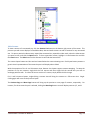
Connect to a Remote DVR
You may need to log in to a higher level account to access this feature.
You can use Transearch to remotely view other sites configured to allow remote connections. An internet
connection is required at both the viewing location and any remote sites. A list of remote sites can be created by
entering the appropriate information into the Remote DVR Configuration page. See Remote DVR Configuration for
more information on adding to or modifying the Site List.
To navigate to the remote Site List, click the Connect button at the top left of the screen and select Remote Sites. If
the Site List is not immediately visible, click the Sites button. The Site List will contain the sites available for remote
viewing. To connect to a remote site, highlight the site in the Site List and click the Connect button. To disconnect
from a site, highlight it under the Current Connections List and click the Disconnect button.
Transearch supports a searchable Site List, enabling administrators to quickly and easily find a site or group that
matches a specified search string. To search for a site, type the search criteria into the Search box and hit the Enter
key or click the Search button. All matching sites will be displayed.
TRANSEARCH TECHNICAL MANUAL
Page 10
Once Transearch has successfully connected to a site you can view the video and data and hear audio all in real time
or you can review past events. To review a site, click on the Review button in the upper left corner of the screen,
and click on the name of the site you wish to review. See Review for more information on how to review video,
data, and audio.
You can return from review to viewing live video and data and hearing live audio by clicking on the Live button in the
upper left corner of the screen.
The Live Camera Viewing Area
The purpose of the Live screen is to display the camera and register views as they record in real time. In Remote
mode, the Remote Live viewing area is on the right hand side of the screen and includes the camera views, camera
layout buttons, Next Page and Previous Page buttons, Video Only or Video & Data, Streams List, and Exit buttons,
as well as an audio volume control. In each camera view there is a camera tag identifying the name of the camera
and the site with which it is associated.
When you click the Video Only button, the camera viewing area expands to take up the entire screen, hiding the live
data streams. When you click the Video & Data button, the live data streams reappear and the video streams
contract to take up only the right hand portion of the screen.
TRANSEARCH TECHNICAL MANUAL
Page 11
A stream refers to any individual camera, register, or audio channel.
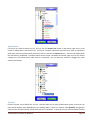
Data Streams
To view a data stream of a remote connected site, click Data in the upper left corner of the screen (if the Site List is
still visible). To change either of the data streams, click the Sites button above a data stream display and select the
site whose data you want to see. Then click the Streams button below the Sites button and select the data stream
you want to see.
TRANSEARCH TECHNICAL MANUAL
Page 12
By default all data streams are available for live viewing when you connect to a site. If you want to close a stream,
you can click on the Streams List button on the bottom right corner of the screen. Expand the site whose data
stream you wish to close, expand the Data node, select the stream you wish to close or click All Data and click Close.
The Hide button on the Streams List will hide the Streams List.
TRANSEARCH TECHNICAL MANUAL
Page 13
Video Streams
To view a camera of a connected site, click the Streams List button on the bottom right corner of the screen. This
presents you with a tree display of all available video, data and audio streams as well as favorites for any connected
site. To open a particular video stream, expand the connected site, expand the video node, select the video stream
you want to view, and click the Open button. To close a particular stream, highlight it in the Streams List and click
the Close button. The Hide button on the Streams List will hide the Streams List.
The camera layout buttons are blue and are located below the camera viewing area. Each layout button presents a
generic visual representation of the camera layout it will display when clicked.
With the exception of the 6- and 24-camera views, Remote Live layouts support camera swapping. To swap the
positions of any two cameras, single-click the first camera and then single-click the second that you wish to
exchange positions with. To view a full-screen version of a camera, simply double-click the image.
For 6- and 24-camera layouts, single-clicking a camera view will bring the camera to a full-screen view. Singleclicking again will revert to the previous layout.
The Previous Page and Next Page buttons will bring up the previous or next page of cameras, respectively. For
instance, if a three-camera layout is selected, clicking the Next Page button once will display cameras 4, 5, and 6.
TRANSEARCH TECHNICAL MANUAL
Page 14
Audio Streams
If there are any audio channels at a site, you can click the Streams List button on the bottom right corner of the
screen to display them in the Streams List. To listen to a channel, expand the site you want to listen to, expand the
audio node, select the audio channel you wish to listen to, and click the Connect button. There may be a delay while
the connection is established. The audio volume control, which is located at the bottom right corner of the camera
viewing area, will indicate which audio stream is connected. You can adjust the volume by dragging the audio
volume control slider.
Favorites
Favorite cameras can be defined for any site. Favorites allow you to group related video streams so that you can
easily switch between them depending on your viewing needs. If there is a Favorite called [Default], that group of
video streams will automatically load up when the site is connected. To open all cameras associated with a favorite
TRANSEARCH TECHNICAL MANUAL
Page 15
and to close all other cameras from that site that are not associated with that favorite, select the favorite item under
the Favorites node and click the Open button.
Adding a Favorite
To define a favorite, open only the video streams that you wish to group together from a specific site. Favorites can
only apply to one site, so open video streams from other sites will not affect the favorite you are defining. When
you have opened only those video streams from a specific site you want to define as a favorite, right click the Video
or site node in the Streams List. Click Add to Favorites and enter a name when prompted. That favorite will now be
available under the Favorites node with the name specified.
Removing a Favorite
To delete a favorite, right click the favorite you wish to remove and click Delete. If you want to stop video streams
from loading up immediately when you connect to a site, you must delete the favorite called [Default].
Saving and Printing Camera Pictures
Clicking on a camera tag brings up a shortcut menu that gives you the option to print or save the current camera
frame.
Selecting the Print option lets you choose between printing a Half Page or a Full Page. Note that a half page prints
the exact same image as a full page except that it is smaller to help conserve ink. After selecting a print option, a
dialog then will open to allow you to choose an available printer from which to print the current image.
Selecting the Save option allows you to save the selected image to a specified location. A dialog box appears that
allows you to select where to save the image. After naming the image and selecting the preferred image format,
click the Save button.
TRANSEARCH TECHNICAL MANUAL
Page 16
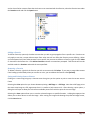
Review
One of Transearch’s most valuable tools is its ability to allow managers and other employees to review POS and
video activity. This feature enables you to pinpoint significant events through sophisticated data- and video-mining
techniques—all from a simple and intuitive user interface. Tracking suspicious activity, trending, and increased
employee manageability and accountability are only a few of the advantages.
To review video, audio, and data, click the Review button in the upper left of the screen. You can search by video
event, or you can search the register data.
Searching by Video Event
To search by video event, click the Search Video button and highlight a camera from the camera list. This will bring
up a calendar icon displaying any year for which there is video as well as display the selected camera in the camera
viewing area if it was not already visible. Expand the year node and select the month and day you want to review. A
list of available video event start times will appear. Click any video event start time to review video from that time.
Click the Play button on the bottom left hand side of the screen to play the video. For more information on the
playback controls, see Playback Controls.
Click the Prev Event and Next Event buttons to jump to the previous video event or the next video event
respectively.
TRANSEARCH TECHNICAL MANUAL
Page 17
Searching with Data
You may need to log in to a higher level account to access this feature.
To review with data, click the Search Data button. Alternately, the Review buttons above the live data streams can
be clicked to bring up the most recent data for instant review.
To pull up a chronological list of a day’s transactions, select the day you wish to search, leave the search box blank
and simply click the Search button. To search for a keyword, type the keyword in the search box, and click the
Search button. Keywords are not case sensitive and do not need to be full words. Matching results will display in
the results box with the corresponding receipt below it.
If you are remotely reviewing a site, past day’s data will only have to be downloaded once. Any search of today’s
data though will require a fresh download every time to guarantee accurate search results.
When a search result item is clicked, video, data and audio are synchronized to the time of the selected search
result. To view the associated video and listen to the associated audio, click the Play button on the bottom left hand
side of the screen. For more information about playback controls, see Playback Controls.
Click the Prev Event and Next Event buttons to jump to the previous search result or the next search result
respectively.
TRANSEARCH TECHNICAL MANUAL
Page 18
The Start at Top of Receipt and Pre-Event Start options can simplify the review process so that you do not have to
play in reverse to get the full picture of the events surrounding a search result. By checking Start at Top of Receipt,
the video, data and audio will be synchronized to the very beginning of the receipt that contained the selected
search result. If Start at Top of Receipt is unchecked and there is a value greater than 0 in the Pre-Event Start box,
then the video, data and audio will be synchronized to a time that many seconds before the selected search result.
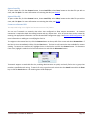
Advanced Data Searches
The Advanced Search options assist in searching the daily database by restricting search parameters. For instance,
you can restrict the parameters by only displaying transactions from a particular cashier, or the search can be
restricted to only display tangible items in a transaction. The Advanced Search options allow you to select only
items that have a particular quantity or amount. You can further restrict a dollar amount search by choosing to only
display items that have even dollars values (for example, $1.00 or $2.00 items would display, but items with cents
would not display). Please note that the Advanced Search may not be available for all interfaces.
TRANSEARCH TECHNICAL MANUAL
Page 19
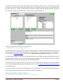
In both the Simple Search and the Advanced Search, Transearch uses the Search Date and the Criteria controls. To
switch to Advanced Search, click the Advanced button. To switch back to the Simple Search, click the same button
(now labeled Simple) again. This will reset all of the advanced search options. In the Advanced Search mode,
several controls will display, allowing you to search by cashier, data type, and amount or quantity. Each of these
options can be used in conjunction with each other.
The Cashier# control contains a list of all the employees in the current day’s data database. If a cashier works on any
of the registers, their name or id number will display in the list. To search transactions by a particular cashier, select
the cashier from the list and click the Search button. Only transactions by the cashier will display. To search by all
cashiers, select the blank option at the beginning of the list. Please note that only interfaces that support cashier
names or ids will be able to use this feature.
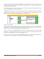
The Type control refers to the data type, or category, of the transaction. There are five possible data types: Item,
Fuel, Cash, Journal and System. The Item data type refers to all tangible items sold. The Fuel data type refers to all
tangible fuel sales (this type is only applicable to interfaces that utilize fuel). The Cash data type refers to all tender
items in a receipt: Subtotal, Total, Tax, Credit, Cash, etc. The System data type only refers to internal messages or
internal interfaces within Transearch. System messages would include alerts from Real Time Monitoring, messages
from the remote access log interface, and Camera Status. All interfaces found under the System data source in the
System Configuration are considered part of the System data type. The last data type is the Journal data type, and it
is a collection of all journal entries from the interface. Essentially, if a particular data does not fall in one of the
other categories, then the data is considered a journal item. Searching by data type is useful if a search criteria
result displays multiple types of data each containing the criteria. To search by data type, select the type from the
list and click the Search button. To disable search by type, select the blank option in the Type list.
Transearch also offers the ability to search for items that meet a certain dollar amount or quantity. For instance,
you can choose to search all transactions over $100 dollars, or all negative transactions. To search by amount, select
“Amount” from the drop-down box. In the next drop-down box, you can choose to search by any amount, or only
even amounts (dollar values ending in “.00”). Even dollar amounts are often the result of manual entry. The next
drop-down box contains the operators for the search. The last box for this option is the value box. Type a positive
or negative number in this box and click the Search button to display the result. To search by quantity, select the
“Quantity” option, the operator, and the search value. The “Even/Any” option is not necessary for the quantity
search.
TRANSEARCH TECHNICAL MANUAL
Page 20
Searching with the Exception List (X-List)
Transearch’s X-List is a state-of-the-art data mining feature that enables managers to set up a list of flags that are
triggered when suspicious activity occurs at the register. This allows for instant event tracking and review at the
click of a button.
To review the X-List items for the given day, choose the Review button, click the Search Data button, enter the
search date, and click the X-List button. The X-List will display a list of user-created flags (such as No Sales and
Voids) along with the number of occurrences for the current day. Items with red buttons have exceeded the
administrator-specified thresholds and are considered critical items.
To view any X-List item, click on its corresponding button to bring up the journal results. Click on any journal item to
synchronize the video, audio and the receipt associated with the selected event.
To configure the X-List, see Configuring the X-List.
TRANSEARCH TECHNICAL MANUAL
Page 21
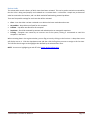
Review Audit
The review audit records a history of which items have been reviewed. This can be used to maintain accountability
that the X-list is being used properly and reviewed on a consistent basis. It also offers a simple way to document
what has occurred at the location, and is an ideal method of bookmarking potential problems.
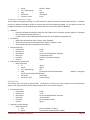
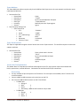
There are five possible settings for each item that will be reviewed:
Clear – Item has either not been reviewed or no decision has been made about the event.
No problem – No problem was found for this exception.
Problem – A problem was found for this exception.
Suspicious – Should be reviewed by someone with administrative or managerial experience.
Training – Exception was caused by an incorrect use of the system; training is recommend to avoid this
exception in the future.
When reviewing data in the register window, you can flag an item by clicking on the line item. A drop-down arrow
will display next to it. Click the drop-down arrow and then click the flag that you want to assign to this line item.
The line item then changes to the highlight color defined by the selected menu item.
NOTE: You can turn highlighting on and off in the Review Audit Configuration.
TRANSEARCH TECHNICAL MANUAL
Page 22
Optional: Auto Review (“No Problem” Flag)
If Auto Review On at Startup is checked in the Review Audit Configuration, reviewed items will automatically be
flagged as No Problem. This way you can cycle through the receipts by clicking on the first search result and then
clicking Next Event. This feature automatically flags each receipt as No Problem. You can of course change the flag
for any item by clicking on the line item, then clicking the drop down arrow to its right and choosing the menu item
that you want to assign to this item.
TRANSEARCH TECHNICAL MANUAL
Page 23
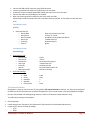
Quick Review
Click the Quick Review Rule button immediately to the right of the GO button to automatically search for a flagged
item. The initials on the button will change to a shortened version of your search (example: NN = Next No Problem,
NP=Next Problem, and PS = Previous Suspicious).
Click GO to repeat the search defined by the Quick Review Rule button (example: If the Quick Review Rule button
displays NP, click the GO button repeatedly to jump to the next several items flagged as Problems).
TRANSEARCH TECHNICAL MANUAL
Page 24
Obtaining a Review Audit Report
See the Reports section on how to view and work with reports.
TRANSEARCH TECHNICAL MANUAL
Page 25
From the Report menu on the tool bar, you can review the Review Audit information in report form. To do this, click
the Review Audit button. The Review Audit report will include audit totals, which indicate how many exceptions
occurred for that item or group. It also includes totals of what was reviewed or not reviewed, as well as totals for
“non-exception” items that were reviewed. These are all reflected in the summary totals.
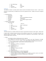
Playback Controls
Transearch’s video controls are intuitive and simple to use, allowing for easy review and playback.
The Play button will synchronize and play through all data and viewable cameras. Selected audio channels will also
play if you are playing at 1x speed.
The Reverse button will synchronize and play through all data and viewable cameras in reverse.
The Pause button will stop playback.
The Replay button will restart playback from the beginning of the last selected search result (See Searching with
Data) or video event (See Searching by Video Event).
The Speed – button will decrease the video playback speed.
The Speed + button will increase the video playback speed.
The <Step button will step back the amount of time indicated in the adjustable Sec threshold box (in seconds) and
synchronize all data and viewable cameras to this time.
The Step> button will step forward the amount of time indicated in the adjustable Sec threshold box (in seconds)
and synchronize all data and viewable cameras to this time.
The < Data button will move the register display back 1 line. The time will be adjusted to the time of the previous
receipt line, and the viewable cameras will be synchronized to this time.
The Data > button will advance the register display forward 1 line. The time will be adjusted to the time of the next
receipt line, and the viewable cameras will be synchronized to this time.
The Camera Viewing Area
Each camera has a tag that states the camera’s name and the time of the current frame. If the camera has been
magnified, the tag will also include the zoom factor (2x, 4x, etc). See Magnifying for more information.
If you are remotely reviewing a site, the Refresh, Clear Cache, and network activity indicator may be visible. The
Refresh button will stop any current downloads and then re-downloads the current video and audio. The Clear
Cache button will delete all cached video, data and audio. You can use either or both of these buttons to help
resolve problems with reviewing a remote site. The network activity indicator will appear whenever anything is
being downloaded from a remote site.
TRANSEARCH TECHNICAL MANUAL
Page 26
Selecting Cameras to View
Click the Camera/Audio Options button. Click the Cameras tab if it is not visible already. Here you can check the
cameras you wish to view. If you are reviewing a remote site, the maximum number of cameras you can view at a
time is set to four by default. See Configure Remote Review Settings to change the maximum number of viewable
remote cameras.
TRANSEARCH TECHNICAL MANUAL
Page 27
Favorites and Default Cameras
Transearch allows you to logically group cameras. These camera groups are called “favorites”. To create a favorite,
first check only those cameras you want to group together from the Cameras tab (click Camera/Audio Options if the
menu is not visible). Then click the Favorites tab. Click Save Current and supply a name for the favorite when
prompted. If you name the group [Default], then this favorite will always load by default whenever you connect to
this remote site or when Transearch starts up on your local system.
If you are reviewing data from a specific register, you may be asked if you wish to associate this favorite with that
data source. This can be helpful when you wish to automatically switch between camera groups depending on the
information you are viewing. For example you could group a few cameras as “Register 1 Cameras” and another
group as “Register 2 Cameras”. By associating these groups with the data sources “Register 1” and “Register 2”
respectively, you can automatically switch between those cameras when you switch between search results from
either data source. This can be especially helpful when reviewing the X-List. To allow favorites to automatically load
depending on the data source being reviewed, check the Auto-change box in the Favorites tab.
To load up the cameras associated with a favorite, select the favorite from the list and click the Open button.
To remove a favorite from the list, select the favorite and click the Delete button.
Camera Options
Right-clicking a camera will open a popup menu with several options. You can also get to these options by left
clicking the camera tag or hovering the mouse over the bottom quarter of a camera until the camera details panel
appears and then clicking the menu button. For the details panel to appear though, the camera must be no less
than one quarter of the viewing area’s size.
TRANSEARCH TECHNICAL MANUAL
Page 28
Caption Location
You can change the corner where the camera tag is displayed. This can be especially helpful if the camera tag is
obscuring something of interest during review.
Email Image
Selecting the Email Image option will bring up the email screen, which allows you to send the current image as an
attachment. For more information about the Transearch Email screen, see Sending Emails.
Print Image
Selecting the Print Image option lets you choose between printing a Half Page, Full Page, High and Low Resolution,
or With Receipt Data. A half page prints the exact same image as a full page except that it is smaller to help
conserve ink. High and Low Resolution will print two images, one half the resolution of the other. This lets you
choose which image actually appears more clear which sometimes can be the lower resolution image. Printing With
Receipt Data will print the currently visible receipt with the image.
A dialog opens to allow you to select an available printer.
Save Image
A dialog box appears that allows you to select where to save the image. After naming the image and selecting the
preferred image format, click the Save button.
TRANSEARCH TECHNICAL MANUAL
Page 29
Save Video
You can save the file of the current video to another folder or disk. To know the start and end time of the clip you
are saving, display the details panel by hovering the mouse over the bottom quarter of the camera. The start time
of the current video file displays on the left and the end time displays on the right. A dialog box appears that allows
you to select where to save the current video. After naming the video, click the Save button.
Advanced Save Video
You may need to log in to a higher level account to access this feature.
You can save a video with the date and time displayed on top of the video. A dialog box appears with options on
how to display the date and time of the video as well as to select where to save the video. After setting the date and
time options and naming the video, click the Save button.
Magnifying
You can zoom in or out of any part of the video. This can be especially useful when reviewing megapixel IP cameras
which cannot display their full detail within the camera viewing area. Right-click a point on the camera you wish to
zoom in on and select Zoom In. When you wish to zoom out, right click the camera and select Zoom Out.
Alternately you can use the plus and minus buttons on the details panel which appears in the bottom quarter of the
video when you hover the mouse over it. You can also use the surrounding arrow buttons to navigate around a
zoomed camera. The zoom factor of the camera will be displayed in the camera’s tag.
Audio Channels
Click the Camera/Audio Options button. Click the Audio tab if it is not visible already. Here you can select the
audio channel you wish to hear during playback if audio is available. Choose No Audio if you do not want to
download or playback audio. Audio will not play unless you are playing forward at 1x speed.
You can adjust the review audio volume with the volume bar on the Audio tab.
If you are remotely reviewing a site, the progress bar on this tab will indicate how much audio has been buffered.
Audio will not begin downloading until the Play button has been pressed.
To save the current audio clip, click the Save Audio button, browse to a location to save the file, name the file, and
click Save.
TRANSEARCH TECHNICAL MANUAL
Page 30
Backing Up Video, Audio and Data
You may need to log in to a higher level account to access this feature.
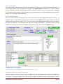
Transearch provides a backup utility to backup video and data for later review. To create a backup, click the Backup
button on the tool bar on the bottom of the screen.
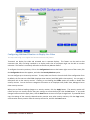
Step One
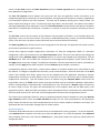
Select the location where you’d like to save the backup. You can check the Show Hard Drives checkbox to display all
fixed drives or the Show Network Drives checkbox to display all network mapped drives. By default, only the
removable drives (CD, DVD, and USB) will appear. See Configuring Transearch and Windows Preferences to change
this default or to prevent some drives from appearing in the list. Click the Refresh button below the drive list if you
have recently inserted a disk or done something to change the size or status of a drive. You can click the plus sign (+)
to the left of a drive to display any existing folders on that drive. You can then check a folder if you wish to copy
your backup to that folder, or you can select the drive to copy the backup to the root folder of that drive. Once you
check the destination drive or folder you wish to backup to, you must verify that there is enough available space
(more than 0 MB). You can enter a name into New Location if you would like the backup to be written to a new
folder in the destination drive or folder you selected. You can then type in a Backup Name or you can leave the
default (NewBackup). We recommend typing something descriptive. Once you are done, click the Next Step
button.
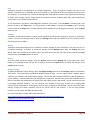
Step Two
Select the time frame of video, data or audio you’d like to back up. Check the items you would like to backup for
that time range and click Add. Note that the entire day’s worth of data is backed up—not a fraction of the day’s
data. To add screen shots or other files to the backup, click the Browse button, browse to the files you want to add,
and click Open. Each backup disk can contain a Transearch installer so as to enable easy review for law enforcement
or others. To include the Transearch installer, check the Playback tools checkbox. If you have added items by
accident or if you need to remove items from the backup because you have exceeded the available space on the
selected backup destination, click an item you wish to remove from the tree view above the Available Space
indicator, and click Remove. You can also start this step over by removing all items from the backup by clicking
Clear. Once you have selected everything you want to backup, click the Next Step button.
TRANSEARCH TECHNICAL MANUAL
Page 31
NOTE: You may use the drop down box for setting the start and end dates but you must manually enter the time
you want to start from by clicking on the “time units” in the box .
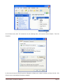
Step Three
Click the Start button to start the backup, or Done to exit. If the backup has started and you wish to cancel it, click
the Cancel button. The progress bar will indicate the progress of the backup as it is being written to the disk or as it
downloads files if you are doing a remote backup. If you are backing up to an optical disk (CD, DVD, etc), the disk
drive will pop open automatically when the backup completes. If there was an error or if you needed to cancel the
backup process for any reason, you can click the Prev Step button, make any changes you need to in Step Two, and
then click Next Step to return to Step Three. You can reattempt the backup by clicking Start again. If you are
performing a remote backup, only those files that had not previously downloaded will have to be downloaded
(unless the cache size was exceeded. See Configure Remote Review Settings to set the cache size). The Backup is
complete when the Start and Cancel buttons are gray and the Done button is your only choice.
Reports
You may need to log in to a higher level account to access this feature.
Transearch offers many reports for a variety of data analytic functions, including Transearch Custom Reports and
Point of Sale (POS) Specific Reports. Custom reports analyze the POS data and report trends, totals and exceptions.
POS Specific Reports are reports generated by the POS and converted to an easy to read format. Please note that
not all POS brands generate reports for Transearch. See Configuring Reports to setup the reports.
All reports can be displayed under the Reports menu by clicking the Reports button along the bottom of the screen.
TRANSEARCH TECHNICAL MANUAL
Page 32
Each report is displayed on the Reports tab in Transearch. Select the report date on the title bar to change the
report date and click a report button to display that report. Selecting a report displays a menu which gives several
options: Preview, Email, Quick Print, and Save. Choose one of these modes to generate the desired report.
Preview a Report
Click the Preview button to view the report. The report will display along with several controls. These controls
allow you to switch between pages (if applicable), print, and save the report to Adobe PDF format. The page control
buttons are represented by arrow buttons. The middle two arrow buttons switch between pages while the two
outside arrow buttons skip to the first or last pages in the report. Click the Print button to print the report. To save
the report, click the Save button. To change the zoom on the report, click the drop-down box and select the desired
display.
TRANSEARCH TECHNICAL MANUAL
Page 33
Email a Report
To email a report, select the report and click the Email button. The email menu will appear. See Sending Emails for
more information on how to send an email.
The report engine allows Transearch to send multiple reports on a single email. To do so, click the Add To Queue
button. The report will automatic be added to a queue for the emails and will not open the email wizard. To open
the wizard, simply click Email for the last report to be sent via email. Click Clear Queue to remove all reports from
the queue.
Quick Print a Report
To quickly print a report, select the Print button. The report will automatically print to the current default printer.
Please note that a printer must be set as the default printer, or the report will generate an error.
Save a Report
Click the Save button to save a report in Adobe PDF format. A “Save As” dialogue will appear, allowing you to select
a destination for the file.
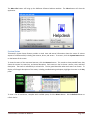
Training
Among Transearch’s user-friendly features is a training manual that is accessible from the software by clicking the
Help button below the camera viewing area and choosing Associate Training. A login box will appear prompting you
to enter a first and last name as well as an identification/employee number. After you log in, a PowerPoint
presentation will appear and allow him or her to select topics for training. After you exit the presentation, a screen
TRANSEARCH TECHNICAL MANUAL
Page 34
stating that you viewed the presentation will appear, and you can hit the Agree button or Disagree button to record
their participation in the training.
Reviewing the Training History
You may need to log in to a higher level account to access this feature.
Managers are often interested in whether or not an employee has viewed the training presentation and accepted
the user agreement. All names and employee IDs are recorded, along with a picture of the employee, in a local
database, which is viewable in the Tutorial History feature of Transearch. This feature can be accessed by clicking
the Configuration button at the bottom right corner of the screen, clicking the Configuration button, then choosing
the Tutorial History option from the menu.
You can email or print the entire tutorial history or, alternately, an individual record, by clicking the Email or Print
buttons on the Tutorial History screen.
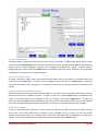
Sending Emails
Transearch’s email feature allows you to email important information and attachments including images and reports
to contacts in your contact list. For the email feature to be usable, a contact list must be configured, along with the
email server settings. See Email Settings for more information.
The email screen provides an intuitive graphic interface for choosing contacts, composing messages, and sending
attachments. The process for sending an email includes adding recipients, adding a subject line, adding a message,
and clicking the Send or Cancel buttons. The Clear button will clear all fields.
Add the appropriate contacts by highlighting them in the contact list tree and clicking the To>> button. To remove a
contact from the list of recipients, highlight the recipient and click the <<To button. Similarly, to add a contact to
the carbon copy (CC) list, highlight the contact and click the CC>> button; to remove a contact from the CC list,
highlight the recipient and click the <<CC button.
TRANSEARCH TECHNICAL MANUAL
Page 35
The subject line text box is located under the Status label on the right hand side of the form. A subject must be
entered for successful email transmission to occur; however, a message is optional. To add a message, type it in the
message box beneath the subject line.
If you are emailing a report or picture, the report or picture will be listed in the attachments drop-down box located
to the left of the Clear button beneath the message box.
The Send button will attempt to send an email to the selected recipients. The Status label will indicate the progress
of the transmission and whether or not it was successful. The Cancel button will cancel email transmission. The
Clear button will clear all email fields. The Done button will exit the email screen.
Taking a Screen Shot
Transearch’s Screen Shot feature allows you to capture an image of the entire screen. This can be useful when you
need to capture an image of the POS data alongside the video for documentation purposes, or if you need to report
a problem or an error to the Gulfcoast Software Solutions development team.
To save a screen shot, click the Screen Shot button underneath the camera viewing area, and choose the Save
Screen option. A dialog box will appear, and you can browse to the location where you would like to save the file,
set the name, and click Save to save the screen shot or Cancel to cancel.
If you wish to print the entire screen, choose the Print Screen option instead. A dialog box will appear where you
can choose your printer and hit Print to print the screen shot, or Cancel to cancel printing.
TRANSEARCH TECHNICAL MANUAL
Page 36
Configuring Transearch
Transearch can be configured by clicking on the green Configuration button on the toolbar in the bottom right hand
corner of the screen. Choose the blue Configuration button to launch your options.
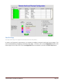
Enabling the On-Screen Keyboard Feature
Instead of relying on the physical keyboard to type and enter data, Transearch supports an on-screen keyboard
feature. The on-screen keyboard displays a visual keyboard with all the standard keys, enabling you to select keys
using the mouse or another pointing device.
This feature can be enabled by clicking on the Configuration button at the bottom right hand side of the screen,
clicking the Configuration button which appears, and choosing the On Screen Keyboard option from the menu. This
will place a checkmark by the option. To hide the on screen keyboard, click the X button in the upper left corner of
the on screen keyboard. To turn off the on screen keyboard, click the On Screen Keyboard option again to remove
the checkmark.
RESULTS: On Screen Keyboard will display whenever text entry is required.
TRANSEARCH TECHNICAL MANUAL
Page 37
Managing User accounts
You may need to log in to a higher level account to access this feature.
Transearch provides multi-user support and access control, allowing managers to lock down the entire DVR or just
certain features. User accounts can be added and the permissions adjusted as needed. Also, a default login can be
set so that a designated user is automatically logged in with the proper permissions every time Transearch is loaded.
To configure user accounts, navigate to the Configuration page by clicking the Configuration button at the bottom
right corner of the screen, clicking the Configuration button that appears, selecting System Configuration from the
menu, and clicking the Security tab.
The User List displays all available user accounts. To add a new user, click the Add button. This will bring up the Add
User form. Enter the new user name and password. Confirm the password, specify a password hint, set the
management and security levels, and click OK to add the new user or Cancel to cancel. To view the user that was
just added, click the appropriate level account (User, Power User, or Supervisor) under the User List. This will
expand the node and display the newly-added user.
To change user permissions and settings, highlight the user in the User List. This will unlock all controls. To add or
take away user privileges, navigate through the tabs below the user list. To enable a specific permission, check it.
To disable it, uncheck it.
The LiveView tab enables or disables viewing live register streams. The Transactions Search tab enables or disables
the ability to search a register. The Camera Permissions tab enables or disables viewing a camera. To limit the
cameras a user can see, you must first check the Limit Cameras checkbox and then uncheck the cameras you want
hidden from the user.
To change a user’s login ID, account type, or security level, highlight the user in the User List and adjust the settings
from the Selected User panel to the right of the User List.
To enable the auto-login account (the account that is automatically logged in whenever Transearch is loaded), click
the Auto Login checkbox under the Selected User pane and type in the login ID of the user you wish to make the
default account.
Click Apply to apply the settings, Cancel to cancel, and OK to apply the settings and exit the Configuration screen.
TRANSEARCH TECHNICAL MANUAL
Page 38
TRANSEARCH TECHNICAL MANUAL
Page 39
System Setting
You may need to log in to a higher level account to access this feature.
Transearch provides flexibility in the look and function of its features and operation, including allowing you to
enable or disable certain Windows items for ease of use. These preferences can be set by navigating to the System
Settings tab of the System Configuration page. To access this page, click the Configuration button on the bottom
right corner of the screen, click the Configuration button, select System Configuration from the menu, and click the
System Settings tab.
Configuring Transearch and Windows Preferences
The first frame in the upper left corner is the frame that contains the settings for preferences, including: the option
to hide the Windows task tray, the option to lock the cursor in Transearch, the option to start Transearch in remote
mode, the option to limit the number of registers available for viewing. These preferences can be enabled or
disabled by checking or un-checking them respectively.
You have the option to set the Store Identification Number. This value can help distinguish one DVR from another.
This value is stored on backups to help distinguish a backup from one site from a backup from another site. You can
see this value in the upper left corner of the screen when you review a backup. It will say “Reviewing: ### Archive”
where ### is the value supplied in the Store Identification Number box.
To save changes and exit the Configuration screen, click the OK button.
TRANSEARCH TECHNICAL MANUAL
Page 40
Configuring Capture Devices
See Connecting to Video Capture Software for more information.
Locking Transearch after User Inactivity
For security purposes, Transearch offers a timeout feature that will lock the software down after an administratorspecified amount of user inactivity. To configure this option, click the Configuration button at the bottom right
corner of the screen, click the Configuration button, choose the System Configuration menu option, and click the
System Settings tab.
Under Do the Following if System is Not In Use panel, select the Review Events Timeout option, enter the number
of minutes of inactivity that will trigger the lockdown, and click the OK button.
Setting the Video Only Password
To set the password for the Video Only Live screen, click on the Configuration button on the bottom right corner of
the screen, click the Configuration button that appears, and then choose the System Configuration option from the
menu. Click on the System Settings tab and enter the password of your choice into the Video Only Screen
Password section. Leaving the password blank will disable the password feature for the Video Only screen, and you
will not be prompted for a password when you exit the Video Only screen.
Configuring the Camera for the Training History
You can elect to record an image of each employee who views the training presentation. The camera used for this
can be configured under the Configuration page. To navigate to the Configuration page, click on the Configuration
button on the bottom right corner of the screen, click the Configuration button which appears, and then choose the
System Configuration option from the menu. Click on the System Settings tab, and then choose the camera you
would like to use to record the training participants within the Tutorial Settings group. Click the OK button to save
your settings and exit this form.
Configure Remote Review Settings
Transearch allows you to adjust certain remote review settings to create a smoother remote viewing experience. To
configure these settings, click on the Configuration button on the bottom right corner of the screen, click the
Configuration button, select the System Configuration option from the menu, click the System Settings tab, and
locate the Remote Review Settings frame on the bottom left side of the screen.
When the Post-buffering feature is enabled, Transearch will automatically download the video or audio that follows
the current video and audio. This can improve the review experience by downloading video and audio before you
need to review them.
When the Pre-buffering feature is enabled, Transearch will automatically download the video or audio that
immediately precedes the current video and audio. This can improve the review experience by downloading video
and audio before you need to review them especially if you are going to play in reverse.
You can also select which of the two, post-buffering or pre-buffering, has priority. By checking Post-buffering
before pre-buffering, you prioritize downloading video and audio that follows the current clips over video and audio
that precedes the current clips.
Because remote review results in increased network activity and uses significant bandwidth, it is recommended that
you set a threshold of the maximum number of cameras that can be reviewed remotely. The suggested maximum is
four, and you should be advised that increasing this number can deteriorate the quality and increase the download
TRANSEARCH TECHNICAL MANUAL
Page 41
time of the remote review experience. To set the maximum number of cameras available for remote review, type
the number in the Maximum viewable cameras in remote review box. Enter -1 if you do not wish to have any limit
(i.e., if you wish to make all cameras simultaneously viewable).
Download Speed sets the packet size for file transfers during data downloads and backup downloads. Setting this
value to LAN can be faster over reliable networks with great bandwidth. For slower, less reliable network we
recommend setting this value to Modem. When set to Modem, downloads may be slower but more reliable.
Similarly, you can set the number of simultaneous downloads that can occur during remote review. To set this
maximum, type the number in the Maximum simultaneous downloads box. Enter -1 if you do not wish to have any
limit (i.e., if you wish to make all download requests run simultaneously or as many as the server will allow). Limiting
the number of simultaneous downloads will limit the amount of bandwidth used. For clients with limited
bandwidth, the speed with which any download completes decreases with every running download request. Also,
the longer a download request takes, the more likely it is to fail. We recommend that client systems with limited
bandwidth limit their simultaneous downloads to 1.
Cache Size defines how many megabytes of downloaded video, audio and data to keep on hand. The cache allows
you to download information once and review it multiple times without having to waste bandwidth and time redownloading the same items. The cache is stored in a subfolder of Transearch and is thus limited to the available
space of the drive Transearch was installed to. Increase the cache size if you find you are re-downloading the same
information too often. Decrease the cache size if you are running into drive space issues.
Configuring the Backup Drive List
Under the Backup Drive List frame on the bottom right corner of the screen, you can check the drives you wish to
make viewable for backups by default. Additionally, you can prevent a drive from being listed in the in the backup
drive list by including its drive letter in the Hide Drives box. For instance, entering “C,Q,F,R” would prevent any
drive C, any drive F, any drive Q and any drive R from appearing in the backup drive list. Use this feature to prevent
users from storing backups on drives that should have limited access or do not have sufficient space to store
backups.
To save changes and exit the Configuration screen, click the OK button.
Configuring the Exception List (X-List)
You may need to log in to a higher level account to access this feature.
To configure the X-List, click on the Exception List button along the bottom of the application.
By default, Transearch displays ten exception list buttons on the X-List. You can scale the X-List window by selecting
the number of the buttons to be displayed using the Limit Exception Button Display drop-down box.
Adding a Rule
The Exception List wizard is divided into several sections. The bar along the top is for setting up the actual exception
rule.
Step 1: The first drop-down box is for setting the criteria category type. This step is optional.
Step 2: The Criteria box sets the search criteria used to find the X-List items. Type the criteria of the exception (e.g.,
type “Void Ticket” for all voided transactions) in this box. This text is not case sensitive.
Step 3: Set the From option to indicate the source of the data to be analyzed.
TRANSEARCH TECHNICAL MANUAL
Page 42
Step 4: Set the Where clause to restrict the results by quantity or amount, by even or any dollar amounts (only if the
amount restriction is selected) and by various mathematical operators (e.g., “>” or “=”). The last option is a
numeric value used to limit the search results.
Step 5: Select the Data Streams. The short list on the left displays all the current POS interfaces. This option is used
to restrict a rule to one or several interfaces. Place a check mark on the interface to apply the rule to that
interface, or choose “All Registers.”
Step 6: Set a threshold for the rule. The Limit option sets the maximum allowed threshold of the exception. The
total number of events will trigger a change in the color of the X-List buttons when it has matched the set
threshold. Zero is the default.
Step 7: Use the Save As option to set the group name for the rule. Exceptions can be grouped together by typing
the same group name for multiple rules. This option is useful if one exception has several different criteria
(i.e., void tickets and error corrects may be identified under the group known as voids).
Step 8: Save the Rule. Click the Add button to save the rule to the X-List.
Editing a Rule
Once a rule has been created, only the Limit and Name fields can be modified. To change either of these options,
select the appropriate field and retype the value over the current value.
Remove a Rule
To remove a rule from the X-List, select the rule on the list and click the Remove button.
TRANSEARCH TECHNICAL MANUAL
Page 43
Configuring Review Audit
You may need to log in to a higher level account to access this feature.
To configure how Review Auditing appears and behaves, click on the Configuration button at the bottom right
corner of the screen, click the Configuration button that appears, and select the Review Audit Configuration option.
To configure how a particular item from your X-List is audited, select it from the table of Exception items. To add or
modify items in the X-List, refer to Configuring the X- List.
You can change the Audit field for any item in the X-List to read either Yes or No. Yes means the item will appear on
the audit report, whereas No means the item will not appear on the audit report.
You can change the Highlight Color and the menu Status color. Click the appropriate button to bring up the color
dialog box. There you can select from standard colors or click Define Custom Color to specify the color of your
choice. We recommend lighter colors. Click OK when you are finished.
The Review Audit feature’s functionality can be turned on or off by checking or un-checking the Review Audit
Enabled option.
By checking Auto Review On at Startup, currently selected items will automatically be flagged as No Problem when
the Play, Reverse, Next Event or Previous Event buttons are pressed.
Checking Show Highlight in Journal and Receipt allows for visual confirmation of items that are reviewed. Items can
still be monitored for whether they have been reviewed or not, even if this is unchecked.
Checking Highlight Mini Mode will cause the journal to display a small, colored highlight to the left of the exception
item. You can set the width of the highlight in pixels by entering it into the text box (a value from 1 to 20).
Checking Highlight Full Line will highlight the full transaction and not just a small area to the left of the exception
item.
Checking Highlight Receipt will highlight the full transaction for the item selected from the search results. This
provides a visual way to match up the item selected from the search results in the receipt window and the full
transaction that it is a part of. You can change the receipt highlight color to your preference. Click the Receipt Color
button to bring up the color dialog box. There you can select from standard colors or click Define Custom Color to
specify the color of your choice. Click OK when you are finished choosing a color.
Some search results may not appear to be associated with any particular transaction. In these instances, setting No
Receipt Number Variance will cause Transearch to highlight all data items captured within (plus or minus) the
number of seconds specified.
When you are finished, click Close and you will be prompted to save your changes.
TRANSEARCH TECHNICAL MANUAL
Page 44
Email Settings
You may need to log in to a higher level account to access this feature.
In order to use Transearch’s email options, it is necessary to configure a contact list and email server settings. This
can be accomplished by navigating to the Email Setup page. To do this, click on the Configuration button at the
bottom right corner of the screen, click the Configuration button that appears, and select the Email Setup option.
TRANSEARCH TECHNICAL MANUAL
Page 45
Creating Email Groups
Transearch supports a group hierarchy within the contact list for ease of use. To add an email group, type in a group
name and click the Add Group button on the left hand side of the screen. A group can be dragged and dropped into
another group to create a subgroup. Contacts can be dragged and dropped into a group. To delete a group,
highlight the group name and click the Delete button on the bottom left of the screen. Deleting a group will delete
all subgroups and copies of contacts within the group.
Create a New Email Contact
To create a new email contact, type in the name and email address into the text boxes on the bottom left of the
screen and click the New button. To delete a contact, highlight the contact and click the Delete button. Deleting a
contact will also delete it from any group it is in; deleting a contact from a group will delete only that copy of the
contact.
Importing and Exporting Email Contacts
Transearch allows you to import contacts from a database or a text file of comma-separated values (CSV), as well as
export the current list to a database or CSV file. To import a contact list, click the Import button on the bottom right
corner of the screen, browse to the database or CSV file of contacts, and click the Open button. To export the
contact list, click the Export button on the bottom right corner of the screen, select a location to save the exported
file to, select the export format (Gulfcoast Email DB file or a CSV file), set the export filename, and click Save.
Email Server Settings
In order to send emails from Transearch, you are required to enter the enterprise email server settings, including
server name, server email, SMTP server, username (if any), password (if any), and port; you may also specify
whether to use authentication, SSL, or HTML format. When you are finished, click the Save button to apply these
settings. To clear your changes and revert back to the previous settings, click the Reset button.
TRANSEARCH TECHNICAL MANUAL
Page 46
To exit the Email Server Settings, click the Close button on the bottom right corner of the screen.
Remote DVR Configuration
You may need to log in to a higher level account to access this feature.
Connecting to remote sites requires that a list of remote sites and their connection information be configured. To
do this, navigate to the Remote DVR Configuration screen by clicking on the Configuration button at the bottom
right corner of the screen, clicking the Configuration button that appears, and selecting the Remote DVR
Configuration option.
Create DVR Groups
Transearch’s remote DVR list supports a group hierarchy for ease of use. To add a DVR group, type in a group name
and click the Add Group button on the left hand side of the screen. A group can be dragged and dropped into
another group to create a subgroup. DVRs can be dragged and dropped into a group or subgroup. To delete a
group, highlight the group name and click the Delete button on the bottom left of the screen. Deleting a group will
delete all subgroups and copies of DVRs within the group.
Adding a DVR Definition
To add a DVR to the list, click the New button. Note: highlighting a group node and then clicking the New button
will create a copy of the DVR within the selected group. Enter the name, IP address, port, username, and password,
and click the Save button to save the information or Cancel to cancel. To place a DVR in a group, drag and drop it to
the group node. To delete a DVR, highlight the DVR and click the Delete button. Deleting a DVR from the All
Contacts node will also delete all copies of the DVR; deleting a copy of a DVR within a group will only delete that
copy.
Importing and Exporting DVR Definitions
Transearch allows you to import DVR lists from a database or a text file of comma-separated values (CSV), as well as
export the current list to a database or CSV file. To import a DVR list, click the Import button on the bottom left of
the screen, browse to the database or CSV file of DVR definitions, and click the Open button. To export the DVR list,
click the Export button on the bottom left of the screen, select a location to save the exported file to, select the
export format (Gulfcoast Server DB file or a CSV file), set the export filename, and click Save.
To exit the Remote DVR Configuration page, click the Close button on the bottom right corner of the screen.
TRANSEARCH TECHNICAL MANUAL
Page 47
Configuring Additional Monitors to Display Live Video
You may need to log in to a higher level account to access this feature.
Transearch can display live video and animated text in separate displays. This feature can be used to alert
customers that they are being recorded or to display areas that an employee might not be able to monitor
otherwise. This feature is commonly referred to as the Security Monitor feature.
To configure the security monitors, click on the Configuration button at the bottom right corner of the screen, click
the Configuration button that appears, and select the Security Monitors option.
You can configure up to six security monitors. To start, select one from the list on the left of the configuration form.
By default, the first two are called EVM (employee view monitor) and PVM (public view monitor). You can apply a
descriptive title to the security monitor. Checking or un-checking the Visible option will enable or disable that
security monitor. You can choose to categorize the monitor as an Employee View, Public View, Manager View or
Other security monitor.
When you are finished making changes to a security monitor, click the Apply button. The security monitor will
refresh and you can visually confirm that your settings are correct before you click the Exit button. If you made
changes but do not wish to apply them, click the Reset button to revert all of your changes back. If you would like to
copy the settings of the currently selected security monitor onto other security monitors, click the Copy button,
select another security monitor from the security monitor list, and click the Paste button.
TRANSEARCH TECHNICAL MANUAL
Page 48
Setting Coordinates
You can set which physical monitor to display the security monitor application on by selecting a monitor from the
Choose a Monitor drop down list. This list will automatically apply the selected monitor’s coordinates to the X and Y
text boxes. You can override these values by manually entering coordinates into the X and Y text boxes. Select the
resolution to display the security monitor by clicking on the resolution drop down control. By default, the security
monitor is set to 800x600.
Choosing Which Cameras to Display
Choose the mode to display cameras from the drop down box below the security monitor title. If you select Quad,
then each of the four cameras you configure will be displayed in a 2x2 layout. If you select Single, only the left most
camera on the configuration form will be displayed. If you select Scan, then only those cameras you check the Scan
option on will be displayed one at a time. Scan mode will rotate through the configured cameras pausing on each
one.
Configuring a Camera
Change the Camera Number box to the index of the GeoVision camera you want to display on the security monitor.
If you want to connect to the camera via GeoVision’s Webcam Server (perhaps you want to display a different DVR’s
cameras), check the Remote checkbox, enter the DVR’s IP address or hostname into the Hostname box, enter the
username and password, and confirm that the Command Port and Data Port settings are correct. By default the
port settings are already set to GeoVision’s default port settings. Remember to check the Scan checkbox for any
camera you want to display in Scan mode.
Editing the Marquee
Click the Edit Marquee button to open up the Marquee configuration. You can set as many as eight marquees with
eight messages each for each of the 6 different security monitors. To start, select the security monitor to configure
a marquee for. Select the marquee you wish to edit. Checking the Display On checkbox enables or disables a
marquee. Now you can enter messages, select the font, color and display type for each of the eight messages on
this marquee.
Set the start time if you want this marquee to begin at a specific time of day. If you are enabling more than one
marquee, it is important to note that a marquee’s start time must be greater than the start time of any previously
defined marquees. For example, Marquee 3 must start later than Marquee 2 if they are both enabled. Otherwise
Marquee 2 will never display.
TRANSEARCH TECHNICAL MANUAL
Page 49
You can also set the location on the security monitor for where you want the marquee to display.
When you are finished making changes to a marquee, click the Apply button. The security monitor will refresh and
you can visually confirm that your settings are correct before you click the Exit button. If you made changes but do
not wish to apply them, click the Reset button to revert all of your changes back. If you would like to copy the
settings of the currently selected marquee onto other marquees, click the Copy button, select another marquee
from the marquee list, and click the Paste button.
Configuring Reports
You may need to log in to a higher level account to access this feature.
The Report Configurator is used to enable and customize various reports.
Navigate to the Report Configurator screen by clicking on the Configuration button at the bottom right corner of the
screen, clicking the Configuration button that appears, and selecting the Report Configurator option.
The Report Configurator hosts the Store Details which configures a site’s Shift and End of Day (EOD) times. Shift
times and the EOD are required for some reports (for example, the Shift Analysis Report).
There are two types of reports: Transearch Custom Reports, and Point Of Sale (POS) Specific Reports. Custom
reports analyze the POS data and report trends, totals and exceptions. POS Specific reports are reports generated
by the POS and converted to an easy to read format. Please note that not all POS brands generate reports for
Transearch.
TRANSEARCH TECHNICAL MANUAL
Page 50
Transearch Reports
There are several Transearch reports: Review Audit Report, the Shift Analysis Report, Training Report, and the X-List
Report. To display all Transearch reports under the Reports menu, check the Transearch Reports box under the
Reports List. To enable or disable a specific Transearch report, select the Transearch Reports button under the
Reports List to display the Transearch Report Configuration menu. Expand the report categories and enable or
disable the desired report by checking the box next to each report.
TRANSEARCH TECHNICAL MANUAL
Page 51
Review Audit Report
This report displays the search activity conducted by the user on the date selected. The report has two sections: the
Exception List (X-List) items reviewed and all general searches (Non Exception Criteria Reviewed Items). There are
several search categories monitored by the report: Audit Total, Not Checked, No Problem, Problem, Suspicious, and
Training. Each category corresponds to one of the Review Audit settings. See Configuring Review Audit for more
information.
Shift Analysis Report
The Shift Analysis report totalizes the business day activities by shift. Each shift is compared with the preceding
weeks of totals from the same day of the week. The report is also divided between general sale information and
departments (user-defined criteria which are customizable). The report analyzes activity to identify trends on the
store level according to several categories: Shift Total sales, Daily Total sales, Shift Percentage of sales, Average
Transaction, Over Rings total, No Sale Count, and Customer Count. Department categories also include the Dept
Quantity Totals, but do not measure over rings, no sales or daily totals as these categories are irrelevant to the
department totals. The general report also lists employee IDs.
Shift Total category measures all monetary sale transactions on the shift.
Daily Total is the total sales for the entire business day.
TRANSEARCH TECHNICAL MANUAL
Page 52
Shift Percentage is the total percentage of shift sales in the Business day.
Average Transaction is the average monetary transaction per customer.
Over Rings measures the total monetary sales of all transaction voids, error corrects, and refunds.
No Sales Count displays all the no sales in a shift.
Customer Count measures the total number of transactions in a given shift.
Employee ID lists all employees actively using the cash register. This category also lists their first transaction time
and their last transaction time.
Dept Quantity Totals counts the total number of items sold in the displayed department.
Each section of the report is followed by the Variance subsection. The Variance percentage is the degree to which
the current selected day’s totals deviate from the averages of the previous weeks. Positive percentages indicate the
value of the current week is greater than the average. Conversely, negative percentages indicate the value is less
than the average. The greater the differences in the percentage, the greater the variance is from the average
category value. If the calculated difference in the variance is the same as the averages, then the variance is at zero
percent. You can define the allowed variances when setting up the Shift Analysis report. Setting the threshold
indicates which variations in the averages are normal and which variation indicates unusual activity. Values that are
beyond the customizable thresholds for that category are highlighted.
The Shift Analysis report also includes the Decision Matrix. The Decision Matrix is a set of rules that seeks to identify
trends by comparing each category’s variances in the Shift Analysis with the other categories (see Shift Analysis
Decision Matrix Setup). Flagged rules are displayed by shift. If no rules have been violated, then Transearch will
display those results.
Please note that Shift Analysis report is only available if the POS interface supports cashiers and Advanced Search.
X-List Report
The X-List Report is a report version of the Exception List (X-List). Just as the X-List displays the totals of each rule, so
the X-List Report lists out all the totals of each rule. Unlike the X-List, the X-List Report does not group together
common name rules, but displays each separately so as to better distinguish the individual components. The report
lists the X-List rule name, the criteria for the rule, the maximum allowed threshold, and the actual number of items
found. There are several different X-List reports. Please note that X-List cashier reports are only available if the POS
brand supports cashiers.
X-List –Business Day: The complete totals for the selected business day.
X-List by Cashier: the X-List totalized by cashier according to standard 24 hours (12:00am to 11:59pm).
X-List by Cashier Business day: the totals for each cashier by business day.
X-List by Cashier –Shift: the X-List totalized for each cashier according to shift.
X-List by Shift: the X-List totals by Shift.
X-List Report: the standard X-List report.
TRANSEARCH TECHNICAL MANUAL
Page 53
Point Of Sale Specific Reports
Point of Sale (POS) Specific Reports are reports generated by the POS and formatted for standard 80 column reports.
This feature requires that the POS sends its reports to Transearch. To enable or disable the report from the selected
category, place a checkmark in the appropriate report box.
Ruby Reports
Currently, the Ruby Dual Printer interface is the only interface that issues reports to Transearch. The VeriFone
Company prints a variety of reports for the Ruby under the Cashier, Shift and Daily report categories. Even though
Transearch is always ready to capture reports, the report display must be configured to locate that specific report in
the daily transaction database. Transearch is configured automatically with a default set of report display
parameters which can be viewed in the Report Configurator under the Pos Specific Reports button.
To add a report to one of the Ruby’s three categories, select the report from the configuration list, choose the
appropriate category, and click the Add button. To permanently remove the added report, select the report and
click the Delete button. Please note that at least one report of that type must be present. Transearch will simply
disable the selected report if no other copy of that specific type of report exists.
TRANSEARCH TECHNICAL MANUAL
Page 54
Store Setup
Various reports generate their totals based on the shift times and the time of the End of Day (EOD). Transearch
allows up to six shifts and a notation for when the EOD occurs. To setup the store details, click the Store Details
button. The EOD setup indicates when the store EOD is expected to occur. It should be set as the last possible time
that an EOD will occur at the store. Indicate when Transearch should totalize the business day totals on the
Generate End of Day Reports notation. Both of these entries should be set for after the normal End of Day has
occurred. Set a start time and stop time for each shift. Set the stop time of the previous shift and the start time of
the next shift to the same time to avoid gaps in the shift times.
Shift Analysis Setup
To setup the Shift Analysis report, click the Shift Analysis Setup button. This will display the setup wizard. Under
the General Settings section, check the Enable Shift Analysis box to enable or disable the report. This option allows
Transearch to generate the totals according to the settings on the Store Details section. Please note that Transearch
totalizes all shift totals once during the day as specified by the Generate End Of Day Reports control in the Store
Details section. The Generate total number of weeks control sets the total number of weeks to be displayed in the
Shift Analysis report. These totals will be used to compare the results of the current week and are useful for
trending. Transearch allows for as few as one week and as many as 52 weeks.
TRANSEARCH TECHNICAL MANUAL
Page 55
The Shift Analysis report totalizes all transactions by employee in a given shift. Since employees occasionally begin
or end their shift before or after the official shift times, Transearch allows a grace period of employee activity. The
Employee Login Time Variation Allowance control sets the total allowed minutes before and after a shift time that a
single employee can process transactions and still be considered part of the shift. Activity outside of the allowed
variance is recorded on the next shift. When the employee works outside of the allowed variance, the activity is
divided between shifts at the set shift time (the variance time is ignored).
Transearch supports multiple types of Shift Analysis reports. That is, a report can have different defined
departments. The Shift Analysis Reports list contains a list of all the Shift Analysis reports. To create a new Shift
Analysis report, click the New button which will create a generic report. Click on the name on the list to modify its
name. To remove a report, select the report and click the Delete button. Click on a report to display and modify its
details. There is a list detailing the main report details and all of the departments below the Shift Analysis Report
list. Expand the nodes to view the details of the main section and the department sections. By default, each
subsection of the main and department sections are enabled. Disabling a subsection will remove the item from a
report. The list of current user-defined departments is located to the left of the details list. To add a new
department, select the department from the department list and click the Add Dept button. To remove a
department for the Shift Analysis report, select the department on the Shift Analysis details list and click the Delete
button.
To set the variance levels for each of the department subsections, select the department subsection from the details
list. This will then populate the Set Report Feature Variance control, which is located just above the available
department list. Modify the variance by clicking the up and down arrow buttons.
Transearch also allows you to recalculate the Shift Analysis totals by using the Generate Shift Analysis Manual
controls. This feature is useful for totalizing a newly added department to the Shift Analysis report. Transearch will
only allow dates that have POS data. Select the start date and the end date. Click the Generate button to reprocess
each of those days. Please note that this may take a while.
To view a sample of the Shift Analysis Report, click the Preview Shift Analysis button.
TRANSEARCH TECHNICAL MANUAL
Page 56
Department Setup
The Shift Analysis reports supports user-defined departments or groups of like events as part of the report’s data
analysis. In other words, you can create special categories of data that are totalized and analyzed in the report. This
department can be added to the Shift Analysis report in the Shift Analysis Setup wizard. To create, modify or delete
a department, click the Department Setup button. The setup window is divided between creating a department and
a list of all available departments. The first step in creating a department is to create a department name. The
department name set here will be the name displayed on the report. After typing a name, select the category from
which the department’s data will be extracted. Click the Add Department button to create the department.
The next setup in creating a department is to add items to the department. Select the department from the
Department List so that the department name is highlighted. Then type the exact data item as it appears in
Transearch on the Item or Value to Search box. This sets the criteria for the department. Any data item that
contains the criteria will be marked as belonging to that department. Click New Item to add the item to a
department. More than one item can be added to the department. The department is now complete. To edit or
delete a specific criteria in a department, select the criteria under the desired department. This will display the item
details in the Item or Value to Search box. To edit the item, make any necessary changes and click the Edit Item
button. To delete the item from the department, click the Delete button. Please note that removing the last item
from a department also deletes the department.
TRANSEARCH TECHNICAL MANUAL
Page 57
Shift Analysis Decision Matrix Setup
As described in the Shift Analysis Report section, the Decision Matrix is a set of rules that help identify trends in the
shift by analyzing the results from the column variances in the Shift Analysis report. Each rule determines if the
actual variance of each column is beyond the bounds of the user-defined allowed variance, and it then compares the
results to all the other columns in that section (the main report or each of the departments). The results can
indicate activity that may be suspicious. Transearch will then search the matrix of rules to find a rule that matches
the set of results, and post the result to the end of the Shift Analysis report. Several default rules are included in the
initial setup.
To configure the Decision Matrix, click the Decision Matrix button to open the setup wizard. The wizard displays a
list of rules and the settings for each rule. To view a specific rule, simply select the rule and its settings will appear in
the controls below. To create a rule, click the New button. Type the name of the rule in the Rule Name box. Each
variation result can either be “No Change” to indicate no significant variation, “Under” to indicate a decrease in that
column, “Over” to indicate an increase in the variation, or “Under/Over” to indicate that a column is simply out of
bounds. Select the appropriate condition for each column to build the rule. Type the reason or symptom that the
rule indicates in the section for the results. Transearch also allows you to insert any notes along with the rule in the
notes section. Click the Save button when setting up the rule is complete. To edit a rule, select the rule from the
TRANSEARCH TECHNICAL MANUAL
Page 58
Decision Matrix Rules list. Make your changes and click the Save button. To permanently delete a rule, select the
rule and click the Remove button.
Export Report Configuration
Transearch has the ability to export select Transearch Custom reports in XML format or in Comma Separated Values
(CSV) format. The CSV format can be read by Microsoft Excel. Transearch will export these files to a local or
network folder. The export files should be deleted by the client after the file is processed. Transearch can be set to
delete the file after a period of days.
To export a particular report, check the box next to the report in the Reports list in the Export Report Configuration
wizard. Select the export file type and choose the file destination. The Browse option will allow you to select a
folder from Windows. To manage the export files, check the Delete old files option and set the number of days in
the Keep Days control. To save the settings, click the Apply button.
TRANSEARCH TECHNICAL MANUAL
Page 59
Scheduling Reports
You may need to log in to a higher level account to access this feature.
Each report can be setup to print or email automatically through the Schedule Reports feature. Only enabled reports
can be scheduled. See Configuring Reports for more information on how to enable a report.
Transearch allows each report to have multiple report generating rules to allow for multiple scenarios. To get to the
Schedule Reports form, click the Configuration button at the bottom right corner of the screen, click the
Configuration button that appears, and select the Report Scheduler option. To enable or disable the report, check
or uncheck the Schedule Reports Enabled option. This feature is divided into three steps: time setup, output mode,
and scheduling the report.
Step 1: Time Setup
Select the appropriate time for the report to generate automatically. By default, all weekdays are enabled.
Disabling a weekday will prevent the report from generating automatically on that weekday. Transearch also offers
the ability to generate a report only one day a month. Choose the Delay Report 1 Day option to ensure that all data
is totalized completely for that report. For example, the X-List Report can be sent after the day is complete,
generating an accurate list of all of the exceptions for that day.
TRANSEARCH TECHNICAL MANUAL
Page 60
Step 2: Output Mode
The Schedule Reports feature currently allows two methods of sending reports: email and automatic printing. To
switch between modes, select the appropriate option on the Output Option drop-down box. To print a report,
select the destination printer from the drop-down box. Printers not found on this list must be setup in Windows
first. To email a report, select the Email Contact from the email contact list. Click the <<To button to set the email
address. Fill in the Subject and the Message.
Step 3: Schedule Report
The list on the left shows all available reports. Only reports that have been enabled will display on this list. To
schedule a report, simply select the report from the report list and click Add>> button, and the report will then be
scheduled using the rules set in Step 1 and 2. The same report can be added to the schedule reports list as long as
the options are different. This allows the same report to be highly customizable. To remove a report from the
schedule list, select the report from the schedule report list on the right. Then, click the <<Report button.
Configuring Data Capture
You may need to log in to a higher level account to access this feature.
Unregistered systems do not support this feature.
Transearch supports multiple connection types including serial, flat file (database files), XML and TCP/UDP direct
connections. Transearch supports up to 48 Point of Sale (POS) and device interfaces simultaneously. Several
TRANSEARCH TECHNICAL MANUAL
Page 61
different interfaces can be setup together in Transearch. Each POS interface connects differently to Transearch, and
must be carefully setup. To reach the Data Configuration screen, click the Configuration button at the bottom right
corner of the screen, click the Configuration button that appears, and select the System Configuration menu option.
The setup tabs for the Data Interfaces are located on the Data Interfaces 1-12, Data Interfaces 13-24, Data
Interfaces 25-36, and Data Interfaces 37-48 tabs. For each interface, check Record Data to enable the interface.
Data Source refers to how the interface connects (serial or TCP). The column labeled Data Device refers to the
specific data controller. For serial interfaces, the Data Device refers to each serial or Com port. Select the desired
serial port. TCP interfaces are interfaces that are found via the network. This interface type includes Flat files, XML,
and TCP/UDP/Multicast direct connections. For network interfaces, the Data Device column refers to a specific Data
Transport. The Data Type column refers to the interface brand. The Incoming number varies from interface to
interface and is very specific to the interface. See the interface details listed below to determine which number
goes in the Incoming field. The Save As drop-down box displays the selected interface as the register position and
number shown in the drop-down box. See Common Names on how to set a register’s name. Raw Capture (RC) is for
debug use only and should remain unchecked for all interfaces.
Serial Port Settings
Serial interfaces require each serial port to be setup properly. If the settings for Transearch do not match exactly
the serial settings of the POS source, then Transearch will not be able to accurately read the data. The serial settings
are located on the Serial Port Settings 1-12 tab and the Serial Port Settings 13-16 tab. Windows XP only supports 16
serial ports. The default settings are as follows:
Baud:
9600
Parity:
Data Bit:
Stop Bit:
Flow Control:
None
8
1
None
Data Transport Settings
All interfaces that are not serial interfaces are configured as TCP interfaces and utilize the Data Transport feature.
The Data Transports are configured on the Data Transport Settings Tab. For interfaces that utilize a single server for
all POS register terminals, only one Data Transport should be setup. For POS registers that transmit their data
independently of the other register terminals, a Data Transport must be configured for each POS register terminal.
Due to the various differences between POS interfaces, not all settings for a Data Transport need to be setup.
TRANSEARCH TECHNICAL MANUAL
Page 62
Features include IP (the IP address of the POS register), Port#, Network Protocol, Path, Reconnect, and mode (Listen
or Connect). Review the settings required for each POS brand.
Advanced POS Settings
The Advanced POS Settings tab consists of advanced features for data capture. Not all features are supported by all
POS interfaces. Features include Automatic Date of Birth Check, Autogas (advanced setup), and Virtual Printer
Setup. The Autogas settings are specific to the Autogas interface. The Virtual Printer Setup is used for specific
interfaces that mimic printers (currently only the Casio interface). The Virtual Printer settings assign response
timings for the device. These settings are divided between serial ports. The Retalix Option “Include Entry Method”
sets whether or not to include the Entry Method in the data stream. The “Fuel Register Override” option is for
Pinnacle Palm only. It allows for outside pump sales to be assigned a register number manually.
Automatic Date of Birth Check
The automatic date of birth (DOB) check allows Transearch to monitor the cashier DOB override feature on the POS.
Additionally the automatic DOB check detects whether or not the cashier quickly enters the current day’s date of
birth. This feature requires that the POS transmits the date of birth of the customer in its data-stream. It works by
searching the data for the date of birth in a recognizable date format and comparing the DOB to the age specified. If
the date is an exact match, the Transearch will assume that the date is an automatic date from the POS and will
insert the display message into the data stream. The message can be searched as an exception item. The Days
column enables Transearch to search by age plus or minus the days specified to modify the dates being searched.
To disable a specific DOB check, set the age to zero.
TRANSEARCH TECHNICAL MANUAL
Page 63
Multiprint Printers
The Multiprint Printers tabs are used to separate data streams from a single, dual or tri printer configuration. This
tab overrides the Save As column on the Data Interfaces tab to direct the data to different register positions in
Transearch. For interfaces that contain multiple printers within a single data source, the data may be duplicated if
these settings are not configured properly. Currently, only the VeriFone Ruby interface uses this feature. The data
is divided according to serial or Com port. Place a check in the box next to the serial device that is used by the
interface configured on the Data Interfaces tabs. Select the first printer and choose one of the Registers to save.
Then, select the printer type (Journal or Receipt). Select the second printer and choose a different register to save.
Select its printer type and choose the other printer type. Repeat for each serial port used.
Common Names
The Common Names tab allows you to change the Save As name for each interface. The name displayed on this list
is the name that is displayed on the main receipt view in Transearch. Common names are divided between Register
Names and Device Names. Register Names change the main interface name found on the Save As column on the
Data Interfaces tabs. The Device Name section allows you to label individual peripheral devices on certain
interfaces. These devices include all temperature monitoring devices. Only interfaces with multiple devices will
display in this section when the interface is enabled. To set the device name, select the interface from Source. Then
choose the device from Data Device and select its device type from the Type list. Write the device name into Device
Name.
Transearch Settings for Point of Sale Devices
Aloha
Aloha POS back office PC transmits all data from each terminal to the DVR via one serial port. Therefore, each
“Incoming” number must be set on the Data Interfaces.
Data Interface Tab
o Record Data
o Data Source
o Data Device
o Data Type
o Incoming
o Save As
Check
“Serial”
Set to next available serial port
“Aloha”
Modify to reflect Aloha terminal #
Ignore
Armored Safe BiComm
Armored Safe BiComm uses the CacheTALK III protocols to communicate with the Armored Safe. This interface does
not require the CacheTALK III device and does not have the advanced features of the CacheTALK III device.
Transearch requires a direct connection to the safe.
Data Interface Tab
o Record Data
o Data Source
o Data Device
o Data Type
o Incoming
o Save As
TRANSEARCH TECHNICAL MANUAL
Check
“Serial”
Set to next available serial port
“Armored Safe BiComm”
Automatically set
Ignore
Page 64
Armored Safe CacheTALK III
Armored Safe CacheTALK III interface requires the use of the Armored Safe CacheTALK III device. The interface
listens to the communication between the Armored Safe and the CacheTALK III device.
Data Interface Tab
o Record Data
o Data Source
o Data Device
o Data Type
o Incoming
o Save As
Check
“Serial”
Set to next available Serial Port
“Armored Safe CacheTALK III”
Automatically Set
Ignore
Armored Safe Serial
Armored Safe Serial receives limited transactions from the Armored Safe and is not recommended.
Data Interface Tab
o Record Data
o Data Source
o Data Device
o Data Type
o Incoming
o Save As
Check
“Serial”
Set to next available Serial Port
“Armored Safe Serial”
Automatically Set
Ignore
AT Systems
See Garda CMS800 interface.
Autogas
The Autogas interface is a network interface and requires that the Autogas and the DVR reside on the same
network. The Autogas requires a separate Data Transport for each register. The prepay and CRIND ghost registers
are assigned to the same Data Transport as the primary register. When assigning Incoming numbers, each Autogas
Register is assigned a number corresponding to that Register’s ID number (“1”, “2”, etc for the actual register). The
Prepay and CRIND ghost are automatically assigned in Transearch with Incoming Numbers of “8” and “9”. These
ghost registers handle all fuel transactions and are necessary for the data. Some older Autogas versions do not have
this feature. Each Incoming number must also be assigned to a register type found on the Advanced POS Settings
tab.
Transearch keeps track of the Autogas journal files automatically. If the Autogas seems to stop recording new data,
and all network communication is still operational, click Reset Autogas to set all of the file settings back to null.
Please note that this will cause Transearch to recapture all previous Autogas Shift receipts.
Data Interface Tab
o Record Data
o Data Source
o Data Device
o Data Type
o Incoming
o Save As
Data Transport Settings Tab
o Data Transport #
IP #
TRANSEARCH TECHNICAL MANUAL
Check
“TCP/IP”
Set to next available Data Transport
“Autogas”
Manually Set: See above
Ignore
blank or default “127.0.0.1”
Page 65
Port #
Blank
TCP / UDP settings
TCP
Path
File Path of *.jnl folder (“m:\pos\”)
Reconnect
Unchecked
Connect / Listen
Default Setting
Advanced POS Settings Tab, Autogas
o Fill in the Incoming field with the incoming numbers used on the Data Interface tab.
o Select the Register type from the Type field
o Incoming “8”
Prepay
o Incoming “9”
CRIND
o Incoming “1-7”
Register
Garda CMS8000 (AT Systems)
The CMS8000 Smart Safe communicates via the UDP protocol. To setup the CMS8000 for data communication,
consult the CMS8000 documentation. Connect the CMS8000 to the local network or via a cross over cable directly
to the DVR. The safe sends data on port 8000 with a subnet mask of 255.255.255.255 (all systems) by default.
Data Interface Tab
o Record Data
o Data Source
o Data Device
o Data Type
o Incoming
o Save As
Data Transport Settings Tab
o Data Transport #
IP #
Port #
TCP / UDP settings
Path
Reconnect
Connect / Listen
Check
“TCP/IP”
Set to next available Data Transport
“AT Safe CMS8000”
Manually set to Data Transport #
Ignore
blank or default “127.0.0.1”
8000 (default)
UDP
Blank
Unchecked
Listen
General Printer
This interface is the most basic and does not allow for any advanced data features.
Data Interface Tab
o Record Data
o Data Source
o Data Device
o Data Type
o Incoming
o Save As
Place a check mark in this box
“Serial”
Set to next available serial port
“General 1” or “General 2”
Automatically Set
Ignore
Gilbarco (G-Site)
There are several different Gilbarco interfaces depending on the Gilbarco version. If communication does not occur
with one interface or is garbled, then try a different interface.
Data Interface Tab
o Record Data
o Data Source
TRANSEARCH TECHNICAL MANUAL
Place a check mark in this box
“Serial”
Page 66
o Data Device
o Data Type
o Incoming
o Save As
Serial Port Settings 1-12 or 13-16 Tab
o Baud
o Parity
o Data Bit
o Stop Bit
o Flow Control
Set to next available serial port
“Gilbarco”
Automatically Set
Ignore
9600
Even
7
1
None
MICROS 3700
The Micros 3700 uses a mapped drive connection to communicate with the Gulfcoast DVR. The Micros 3700 back
office server and the Gulfcoast DVR must reside on the same network. Create a mapped drive connection to the
drive containing the Micros journals. The Default path is “D:\Micros\Res\Pos\Journals.” In addition, the batch file
that manages the End Of Day journal archive must be modified to include two lines that notify Transearch.
Windows
o Set IP protocol to Micros 3700 server
o Map Micros Drive containing Micros Journals (Map to d-drive). Use the “M:\” as the drive letter.
o Edit the RenameJournals.bat file by inserting these two lines. Note that the lines must be inserted
before the line that deletes the journals (“del …”)
for %%i IN ("D:\Micros\res\pos\journals\*.txt") do echo End OF Day >> %%i
@ping 1.1.1.1 /n 1 /w 3000
Data Interface Tab
o Record Data
Check
o Data Source
“TCP”
o Data Device
Set to next available Data Transport
o Data Type
“Micros 3700”
o Incoming
Number of Current Register
o Save As
Ignore
o Raw Capture (RC)
Gulfcoast Use Only
Data Transport Settings Tab
o Data Transport #
IP
Ignore
Port #
Ignore
TCP / UDP settings
TCP
Path
File Path of Journals on Micros.
Default: “M:\Micros\Res\Pos\Jounals\”
Reconnect
Unchecked
Connect / Listen
Default Setting
Common Names Tab
o For each terminal, type the exact name of the terminal in the corresponding Register Name section.
o Names of each terminal can be retrieved from the Journal text file found at the file path set above.
o This is required for use of the Micros 3700.
Troubleshooting:
o If new transaction data is not received by Transearch, but all settings and cabling are correct, then it
may be necessary to reset the Transearch Micros file handling settings.
o Exit Transearch
o Locate the “INI” folder in the Transearch directory.
TRANSEARCH TECHNICAL MANUAL
Page 67
o
o
o
Default path is “C:\Program Files\Transearch\INI”
Select the “Transearch_POS_Advanced.ini” file and open it.
Locate the Micros 3700 tag and reset the values to 0
File Size1=0
Line Number1=0
POS File Count=0
Launch Transearch. Transactional data should flow.
MICROS Serial, MICROS-IDN.
This interface uses a connection to the register’s printer
Data Interface Tab
o Record Data
o Data Source
o Data Device
o Data Type
o Incoming
o Save As
Place a check mark in this box
“Serial”
Set to next available serial port
“Micros Serial”, “Micros-IDN”
Automatically Set
Ignore
Oneac
The Oneac is an uninterrupted power supply (UPS) and includes software for monitoring the electrical power
entering into the Oneac. The Oneac interface monitors Oneac activity via the Oneac software. Connect the Oneac
to the DVR through a standard USB cable.
Data Interface Tab
o Record Data
o Data Source
o Data Device
o Data Type
o Incoming
o Save As
Network / System Settings
o Data Transport #
IP #
Port #
TCP / UDP settings
Path
Reconnect
Connect / Listen
Check
“TCP”
Set to next available data transport
“Oneac UPS”
Set to Register Number
Ignore
Blank or default “127.0.0.1”
Default
TCP
Path to Oneac Software.
Unchecked
Listen
Osprey
This interface uses a connection to the register’s printer.
Data Interface Tab
o Record Data
o Data Source
o Data Device
o Data Type
o Incoming
o Save As
TRANSEARCH TECHNICAL MANUAL
Check
“Serial”
Set to next available serial port
“General 1” or “General 2”
Automatically Set
Ignore
Page 68
Panasonic
Concerns Panasonic models JS-750, JS-5500, and JS-7500. This interface is a data only interface and does not have
advanced features enabled.
Data Interface Tab
o Record Data
o Data Source
o Data Device
o Data Type
o Incoming
o Save As
Check
“Serial”
Set to next available serial port
“Panasonic…” model number.
Automatically Set.
Ignore
Passport (Serial)
The serial passport interface ties directly into the poll display of the Gilbarco Passport. The poll display is a serial
device that connects directly to the Passport via the Edge Port on the Passport, and it is always on.
Hardware Setup
o Detach poll display from the Edge Port.
o Attach female DB9 to RJ45 (standard pin out) to the port.
o Insert a RJ45 Splitter to the DB9 to RJ45 converter.
o Plug in a short Cat5 patch cable into the splitter.
o Attach a male DB9 to RJ45 (standard pin out) to the cable.
o Connect the Poll Display to the male DB9 converter.
o Cat5 cable to the DVR will plug into the splitter.
For the cable, only use one pair of wires.
Use pins 3 and 5 on the POS side.
Use pins 2 and 5 on the DVR.
The wire for pin 3 on the POS side goes to pin 2 on the DVR.
o Pin out a female DB9 to RJ45 (standard pin out) and connect to an available serial port on the DVR.
Data Interface Tab
o Record Data
Check
o Data Source
“Serial”
o Data Device
Set to next available serial port
o Data Type
“Passport”
o Incoming
Automatically Set.
o Save As
Ignore
Passport (XML)
Review the Passport Setup document on configuring the Passport. The Passport must be version 5 or greater. Use
the Passport Serial interface for earlier Passport versions.
Data Interface Tab
o Record Data
o Data Source
o Data Device
o Data Type
o Incoming
o Save As
Data Transport Settings Tab
o Data Transport #
IP
TRANSEARCH TECHNICAL MANUAL
Check
“TCP”
All Registers listed on same DT
“Passport XML”
Number of the Register
Ignore
Ignore
Page 69
Port #
TCP / UDP settings
Path
Reconnect
Connect / Listen
Default: “10101”
TCP
Ignore
Unchecked
Listen
PC Measure Temperature Gauge
The PC Measure Temperature Gauge is a serial device from which Transearch retrieves data indirectly. Transearch
uses the PC Measure software’s log files to retrieve data from the temperature gauge. For the device to work, the
PC Measure software must be setup properly with a shortcut in the Startup folder of Windows.
Windows
o Install the PC Measure software under the Tools folder of the Transearch directory (default: C:\Program
Files\Transearch\Tools\PC Measure”)
o Create a short cut in the Windows Startup folder for the PC Measure executable file.
PC Measure
o Specify the serial devices used in ‘Setup,’ then ‘Hardware’
o Disable all serial ports not being used in the ‘Setup’ ‘Hardware’ menu.
o Set the display to show the appropriate serial device.
Data Interface Tab
o Record Data
Check
o Data Source
“TCP”
o Data Device
Set to next available Data Transport
o Data Type
“PC Measure Temp”
o Incoming
Number of the Data Transport
o Save As
Ignore
Data Transport Settings Tab
o Data Transport #
IP
Ignore
Port #
Ignore
TCP / UDP settings
TCP
Path
File Path of the PC Measure folder.
Default: “C:\Program
Files\Transearch\Tools\PC Measure”
Reconnect
Unchecked
Connect / Listen
Default Setting
Pinnacle Palm
The Pinnacle Palm transmits its data by XML. The DVR must reside on the same network as the Pinnacle Palm
system. Each Palm terminal must be setup individually with its own Data Transport.
Data Interface Tab
o Record Data
o Data Source
o Data Device
o Data Type
o Incoming
o Save As
Network / System Settings
o Data Transport #
IP #
Port #
TRANSEARCH TECHNICAL MANUAL
Check
“TCP”
Set to next available Data Transport
“Pinnacle Palm”
Set to Register Number
Ignore
blank or default “127.0.0.1”
Port Number of Palm (default: 13740)
Page 70
TCP / UDP settings
Path
Reconnect
Connect / Listen
TCP
Blank
Unchecked
Listen
POSitouch
The POSitouch interface is an XML network interface and uses the POSitouch Electronic Journal. In order for the
POSitouch to transmit data, the POSitouch must have the appropriate license. SPCWin must also be configured
properly.
Data Interface Tab
o Record Data
o Data Source
o Data Device
o Data Type
o Incoming
o Save As
Network / System Settings
o Data Transport #
IP #
Port #
TCP / UDP settings
Path
Reconnect
Connect / Listen
Check
“TCP”
Set to next available Data Transport
“POSitouch-EJ”
Set to POSitouch register number
Ignore
“127.0.0.1”
“5015” is default port
TCP
Blank
Unchecked
Listen
Retalix
The Retalix interface is a network interface that requires a separate Data Transport for each register. Retalix sends
its data via XML. All Retalix registers settings must be modified to transmit data. The settings are located in the
Windows Registry of each register. The registry should only be modified by a trained individual. Please consult
Gulfcoast Support before continuing.
Retalix
o Exit the Retalix software. Manager permission is required.
o Click the Start button of Windows and select Run. Type “regedit” at the “Open” dialogue box. Click OK.
o All Registry Settings are located at “HKEY_LOCAL_MACHINE\SOFTWARE\Positive\Positive32\”
This is the Main folder. All other folders can be found from this root.
o Folder “Terminal”
For TCP Direct, modify key “UseTcpDirect”
UseTcpDirect = 1
o Folder “LocalServers\TcpDirect”
XMLFormat = 1
HostName = IP address of the DVR
Port = 2002
SaveQueueFile = 0
o Folder “Events\<Event Number>.” For Documentation ONLY.
Gulfcoast Software Solutions use only. Do Not Use.
The Events folder has several subfolders that are specific to particular events on the Retalix.
Enable all subfolders that have the following value: TcpDirectEvent
TcpDirectEvent = 1
TRANSEARCH TECHNICAL MANUAL
Page 71
Please note, pos reports may be available at Event 1015.
Data Interface Tab
o Record Data
Check
o Data Source
“TCP”
o Data Device
Set to next available Data Transport
o Data Type
“Retalix”
o Incoming
Number of the Data Transport
o Save As
Ignore
Data Transport Settings Tab
o Data Transport #
IP
Ignore
Port #
Ignore
TCP / UDP settings
TCP
Path
Blank
Reconnect
Unchecked
Connect / Listen
Listen
RMS (Retail Management Solutions)
This interface works with the RMS Keystroke program developed by Ideal Computer Solutions. The program is
installed on the RMS system.
Data Interface Tab
o Record Data
o Data Source
o Data Device
o Data Type
o Incoming
o Save As
Check
“Serial”
Set to next available serial port
“RMS”
Automatically Set
Ignore
Ruby (Dual Printer)
Ruby dual printer setup is the legacy VeriFone register system. Connect to the Ruby printer using a standard ruby
kit.
Data Interface Tab
o Record Data
Check
o Data Source
“Serial”
o Data Device
Set to next available serial port
o Data Type
“Ruby”
o Incoming
Automatically Set
Mulitprint Printers Tab
o Enable for Corresponding Comm Port set by “Data Device” on the “Data Interface” tab
o Multiple Printer Enabled
Check
o Printer 1
Set to Desired Register ID
o - drop-down list
“Journal”
o Printer 2
Set to Desired Secondary ID
o - drop-down list
“Receipt”
o Printer 3
“None”
o - drop-down list
“None”
TRANSEARCH TECHNICAL MANUAL
Page 72
Ruby Thermal Printer
Ruby thermal printer is generally considered a “print on demand” interface and does not transmit all transactions.
Certain transactions can be forced to print from the Ruby. A trained VeriFone technician is required to modify the
Ruby settings.
Data Interface Tab
o Record Data
o Data Source
o Data Device
o Data Type
o Incoming
o Save As
Check
“Serial”
Set to next available serial port
“Ruby”
Automatically Set
Ignore
Ruby Virtual Journal
Virtual Journal is a VeriFone product and is supported through the Virtual Journal Port (typically Com5) on each
Ruby.
Data Interface Tab
o Record Data
o Data Source
o Data Device
o Data Type
o Incoming
o Save As
Place a check mark in this box
“Serial”
Set to next available serial port
“Virtual Journal”
Automatically Set
Ignore
Sapphire CRIND Serial
Virtual Journal and Sapphire Serial is a VeriFone product and is supported through the Virtual Journal Port on each
Ruby or Topaz terminal.
Data Interface Tab
o Record Data
o Data Source
o Data Device
o Data Type
o Incoming
o Save As
Place a check mark in this box
“Serial”
Set to next available serial port
“Sapphire”
Automatically Set
Ignore
SensaTronics Temperature Gauge
The SensaTronics Temperature Gauge is a serial device. Use standard Cat5 and DB9 to RJ45 converters that are fully
pinned out.
Data Interface Tab
o Record Data
o Data Source
o Data Device
o Data Type
o Incoming
o Save As
TRANSEARCH TECHNICAL MANUAL
Check
“Serial”
Set to next available serial port
“SensaTronics Temp”
Automatically Set
Ignore
Page 73
Subshop 2000
This is a network interface. Transearch can connect to the Subshop 2000 register either directly through the
network IP address, or through a mapped drive connection. If the Windows version of the Subshop 2000 is
Windows Server 2000 or later, then the Subshop 2000 supports the mapped drive connection. This is the preferred
method of connecting to the Subshop 2000.
Data Interface Tab
o Record Data
Check
o Data Source
“TCP/IP”
o Data Device
Set to next available Data Transport
o Data Type
“Subshop 2000”
o Incoming
Manually Set: Data Transport #
o Save As
Ignore
Mapped Drive Connection Method (Do not follow if using IP Address Connection Method)
o Data Transport Settings Tab, Data Transport #
IP
“127.0.0.1” or blank
Port #
Blank
TCP / UDP settings
TCP
Path
“M:\” – The mapped drive.
Reconnect
Unchecked
Connect / Listen
Default Setting
IP Address Connection Method (Do not follow if using Mapped Drive Connection Method)
o Data Transport Settings Tab, Data Transport #
IP
IP Address of Subshop Register
Port #
Blank
TCP / UDP settings
TCP
Path
“Proqueue\”
Reconnect
Unchecked
Connect / Listen
Default Setting
Tidel Smart Safe
The Tidel safe streams XML through the TCP Protocol. The Tidel safe and the Gulfcoast DVR must reside on the
same network. The Tidel safe must also be setup to transmit data.
Data Interface Tab
o Record Data
o Data Source
o Data Device
o Data Type
o Incoming
o Save As
Data Transport Settings Tab
o Data Transport #
IP #
Port #
TCP / UDP settings
Path
Reconnect
Connect / Listen
TRANSEARCH TECHNICAL MANUAL
Check
“TCP/IP”
Set to next available Data Transport
“Tidel E Safe”
Manually Set: Set to Corresponding Register
Ignore
blank or default “127.0.0.1”
Port Number of Tidel stream (default: 4887)
TCP
Blank
Unchecked
Listen
Page 74
Topaz Multicast
The Topaz Multicast solution requires only that the DVR and the Topaz are on the same network and that the router
used supports Multicast.
Data Interface Tab
o Record Data
o Data Source
o Data Device
o Data Type
o Incoming
o Save As
Data Transport Settings Tab
o Data Transport #
IP #
Port #
TCP / UDP settings
Path
Reconnect
Connect / Listen
Check
“TCP/IP”
Set to next available Data Transport
“Topaz Multicast”
Manually set to the Topaz register
Ignore
“230.0.0.1”
“14001”
“MCast”
Blank
Unchecked
Listen
Topaz Virtual Journal
The Topaz is supported through the Virtual Journal Port on the Topaz terminal. This interface requires a router that
supports multicast.
Data Interface Tab
o Record Data
o Data Source
o Data Device
o Data Type
o Incoming
o Save As
Place a check mark in this box
“Serial”
Set to next available serial port
“Topaz”
Automatically Set
Ignore
Veeder-Root TLS Tank Monitor
The Veeder-Root TLS Tank Monitor interface sends requests to the TLS, and receives reports that indicate tank
levels, system alerts, and fuel deliveries. *Now works for both Serial and TCP/IP connections.
Device Setup
Use any available 25 pin serial port on the TLS Device. If no serial ports are available, then a TLS serial card
must be installed.
Connect a DB25 to DB9 converter to the serial port on the TLS.
Pin out a male DB9 to RJ45 converter on the TLS as follows:
o TLS DB25 port
Orange 2
Black
3
Green
7
Alternately, a DB25 to RJ45 converter may be used.
o TLS DB9 port
Orange
3
Black 2
Green 5
TRANSEARCH TECHNICAL MANUAL
Page 75
Connect the DB9 to RJ45 converter to the DB25 converter.
Connect a standard Cat5 cable to the RJ45 port on the converter.
At the DVR, make a standard female DB9 to RJ45 and connect it to the Cat5 cable
Connect the cable to an available port on the DVR.
Note: Serial settings can be modified on the TLS to match the DVR.
Please keep in mind the Veeder-Root TLS is the ONLY two way interface, in that codes are sent back and
forth.
Storekeeper Setup
(TCP/IP)
Data Interface Tab
o Record Data
o Data Source
o Data Transport
o Data Type
o Incoming
o Save As
Place a check mark in this box
“TCP/IP” or “Serial”
IP Address of the Veeder Root Device
“Veeder-Root TLS”
Automatically Set
Ignore
Storekeeper Setup
(Serial Settings)
Data Interface Tab
o Record Data
o Data Source
o Data Device
o Data Type
o Incoming
o Save As
o Raw Capture (RC)
Serial Port Settings
o Serial Port #
Baud
Parity
Data Bits
Stop Bits
Flow Control
Check
“Serial”
Set to Desired Transport
“Veeder-Root TLS”
Automatically Set
Sets Storekeeper Device ID
Gulfcoast Use Only
1200
Odd
7
1
None
TLS Control Characters
Storekeeper is setup to connect to the TLS using default TLS control characters. However, the TLS may be configured
for different control characters than its default configuration. There are two values in the Query/Request messages
that are customizable: the SOH beginning character, and the ETX character (ASCII characters only).
To modify these settings in Storekeeper:
Exit Storekeeper.
Locate and open the Transearch_POS_Advanced.ini file located in the Storekeeper\INI directory.
Locate the TLS section and edit its settings.
o [TLS]
o SOH=
TRANSEARCH TECHNICAL MANUAL
Page 76
o ETX=
o SecurityCode= (see below)
Save the settings and close the file.
Launch Storekeeper.
TLS Security Code
The TLS may also have a six digit security code. The security code authenticates requests from the DVR. By default,
no security code is required. To add a security code, follow the above steps for modifying the TLS control characters.
Update only the SecurityCode value.
Testing the TLS through HyperTerminal
To test the TLS cabling through HyperTerminal, connect to the TLS using the above section on Device Setup. Open
HyperTerminal and configure the appropriate serial port.
Holding down the control key, press the ‘A’ key on the keyboard. A smiley face should appear ().
Type I20100 immediately following the smiley face.
Press the Enter key.
Data should start flowing immediately.
If no data flows, then check the cabling.
Wand
The Wand is a serial interface that is connected through the printer.
Data Interface Tab
o Record Data
o Data Source
o Data Device
o Data Type
o Incoming
o Save As
Place a check mark in this box
“Serial”
Set to next available serial port
“Wand”
Automatically Set
Ignore
Wayne Nucleus
Wayne Nucleus Data transmits all data through only one serial port. All registers are given an Incoming
Identification Number to distinguish each Register in the Nucleus. This number corresponds to the Incoming
number set on the Data Interface tab. For each Register on the Wayne Nucleus System, a corresponding Register
slot must be added with the corresponding Incoming Number (ex: “Register 2” possesses the Incoming number of
“2”). All serial ports for each register are set to the same serial port.
Data Interface Tab
o Record Data
o Data Source
o Data Device
o Data Type
o Incoming
o Save As
Check
“Serial”
Set to next available serial port
“Wayne Nucleus”
Manually set for each Register
Ignore
Wayne Plus
Wayne Plus data receives its data from each of the terminals via the printer.
Data Interface Tab
TRANSEARCH TECHNICAL MANUAL
Page 77
o Record Data
o Data Source
o Data Device
o Data Type
o Incoming
o Save As
Serial Port Settings 1-12 or 13-16 Tab
o Baud
o Parity
o Data Bit
o Stop Bit
o Flow Control
Check
“Serial”
Set to next available serial port
“Wayne Nucleus”
Manually set for each Register
Ignore
4800
None
8
1
None
Configuring Real Time Monitoring
You may need to log in to a higher level account to access this feature.
Real Time Monitoring (RTM) enables you to monitor specific events in real time that occur on any data interface.
When an event occurs, RTM will immediately notify you of the event through customizable alerts (see Creating Real
Time Monitoring Alerts). RTM is designed to monitor multiple events from multiple devices simultaneously. It can
monitor a single event or a group of events. RTM can track events that occur on a single device or events that occur
between devices (i.e., Safe Drops between the POS and a Smart Safe). RTM can monitor specific transactions that
meet a specific cash value or quantity. RTM also has the ability to totalize amounts and quantities within an event
group. When an expected event does not occur or when an unexpected event does occur, RTM can be set to issue
any dynamic alert you set.
One of the features of RTM is the Floating Time Point technology that can determine if a certain number of events
have occurred within a specified period of time. For example, you can configure RTM to alert you only in the event
that five “No Sales” have occurred within an hour. Real Time Monitoring is designed to handle virtually any possible
combination of events imaginable.
To configure Real Time Monitoring, click the Configuration button at the bottom right corner of the screen, click the
Configuration button that appears, and select the Real Time Monitoring option.
A rule is a group of events that allow Transearch to monitor a specific event, or series of events, and trigger an alert
if required.
Each group is comprised of one or more events that can cause an alert. In a group of two or more
events, the first event must occur before the next event is monitored. For instance, assume there is a rule that
checks for safe drops from the register and ensures that the drops get to the safe. A “Safe Drop” must occur on the
Point of Sale (POS) before RTM will start checking the safe for a “Safe Drop.” If the safe receives a “Safe Drop”
without one occurring on the POS, RTM would ignore the event because that event has not yet been activated in the
rule. If the “Safe Drop” event occurs on the POS, Transearch will monitor the safe until either the safe drop has
occurred, or the rule has timed out which will result in an alert being issued.
To create a Real Time Monitoring rule, click the Create Rule button. Type the name of the rule in the Rule Name
section and then click the >> button. This will open the settings windows. There are six steps for configuring a rule.
See the sections below for information on each of the steps. To move between windows, click the Next and
Previous buttons. On the last step, click the Save button. The rule will display on the rule list along with a brief
summary of the various selected options. Click the rule to expand and view all events listed on the rule. Click the
TRANSEARCH TECHNICAL MANUAL
Page 78
rule name again to modify the name. To edit a rule, click the Edit Rule button, which will open the settings window.
Click the Save button on Step 6 to save any changes. To enable or disable a rule, check or uncheck the rule. To
delete a rule, select the rule and click the Remove button.
Real Time Monitoring possesses six main configuration settings when creating a rule. They are Limit Data-stream,
Schedule Time, Time Frame / Time Out, Event Limits, Select Alerts, and Select Criteria.
Limit Datastream
A rule can be set to monitor all devices or interfaces, or the rule can specify specific devices. Selecting the Monitor
all Devices option will set RTM to examine all data from all devices and interfaces. Selecting Monitor Select Devices
will open the device selection options. The list on the left, labeled Available, displays all the currently enabled
interfaces on the DVR. The list labeled Monitor Device displays the current devices to be monitored. If no devices
are on the Monitor Device list, then RTM will be set to monitor all devices. To add a device to the monitor list, select
the device from the Available list and click the Add button. To remove a device from the Monitor Device list, select
the device and click the Remove button.
TRANSEARCH TECHNICAL MANUAL
Page 79
Schedule Time
This option allows you to set a time when the rule is enabled. A rule can be enabled for a specific time or for a day
of the week. To set a time schedule for the rule, check Enable Schedule Time. Then set the Start Time and the End
Time. Start and end times cannot be the same time. Please note that if the start and end times are both “12:00:00
AM,” the rule will monitor all times. By default, all days of the week are monitored. To disable a rule from a
particular day, uncheck the day of the week. At least one day should be enabled, or RTM will not function.
TRANSEARCH TECHNICAL MANUAL
Page 80
Time Frame / Time Out
Each rule is monitored on the basis of time. When the first event occurs in a rule, the next event in the rule must
occur within the specified period of time for any additional action to occur. Otherwise, the rule is reset and RTM will
no longer check for the next event. RTM rules monitor time via two main ways: events that occur within a “Time
Frame” and events that “Time Out”. Under the Time Frame option, an alert is issued when a total number of events
in a group exceed a specified limit within the allotted time frame. A Time Out issues an alert when an expected
event does not occur within a specified amount of time (the clock will countdown until it expires, triggering an alert).
If only one event criteria is set, the Time Out option will activate immediately, beginning the countdown as soon as
the rule is activated. Otherwise, the first event in the rule will trigger the clock to countdown as normal.
Select either the Time Frame option, or the Time Out option. Use the Set Time control to set either the Time Frame
window, or the Time Out countdown. The control is divided between hours (HH), minutes (MM), and seconds (SS).
The times can be set manually, or by using the arrow keys.
TRANSEARCH TECHNICAL MANUAL
Page 81
Event Limits
Transearch can monitor events by counting the number of times that the event occurs, or it can monitor events by
counting the total monetary amount or quantity for the whole event group. Selecting the option for Count by
Occurrence will set the rule to count the number of times that event occurs. This threshold is set by the Monitor by
Occurrence control. This option is useful for monitoring the total number of “No Sales” and other like criteria.
To count the monetary amount and/or the quantity of an event group, select the Count by either Money or
Quantity option. This option will display the Monitor by Totals controls and give the option to either manually
define the limits (the User defines limits option), or have the preceding criteria set the threshold for the current
event (Device determines limits option). Manually setting the quantity and amount limits opens the Static Count
Settings control panel.
With the Static Count Settings controls, you can set the cumulative total threshold for the entire group. When the
event group reaches this total in either quantity or amount, an alert is issued, regardless of the number of events.
Setting the Quantity Limit or the Amount Limit value to zero disables this threshold. The Any/Even option allows
you to check any dollar amount (choose “Any”) or only dollar amounts that do not have cents (choose “Even”). The
Operator option tells the rule how to flag the totals (the greater than equal to symbol is default, “>=”). Please note
that only the last event in the rule is totalized.
TRANSEARCH TECHNICAL MANUAL
Page 82
The Device determines limits option is used when a preceding event automatically sets the amount threshold for
the last event in the rule. The RTM rule will then verify that the last entry is equal to the threshold set by the
preceding event. For example, if RTM is monitoring “Safe Drops” from the register to the safe, the register pos
transaction would automatically set the rule to the amount of the safe drop. When the smart safe counts the
money from the drop, RTM will verify that all the money taken from the register in the safe drop was deposited into
the safe. If the rule times out before the total is reached, Transearch will issue an alert. This option requires at least
two criteria in the RTM rule.
Select Alerts
The Select Alerts window allows you to choose which alerts will be issued if the rule is triggered by an event. RTM
will issue escalating alerts up to three alert levels if the problem is not resolved promptly. For the Time Frame
option, RTM will issue an elevated level alert if RTM receives another criteria that sets the event over the accepted
threshold. For example, if three “No Sales” result in an alert being issued, then Transearch will issue another alert if
it detects another “No Sale.” For the Time Out option, RTM will issue the next level alert if the expected event does
not occur within the countdown process. In the “Safe Drop” example, Transearch will continue to issue alerts until
the safe receives the drop.
This section is divided into a list of the available alerts, and the list of currently enabled alerts. To add an alert to the
rule, select the alert from the list and choose the appropriate alert level. Selecting the ALL option will set the alert
TRANSEARCH TECHNICAL MANUAL
Page 83
to issue at all alert levels. Click the Add button to enable the alert. The alert will appear on the enabled alerts list
with current alert level. To remove an alert, select the alert from the enabled alert list and click the Remove button.
To create a new alert not currently on the list, click the Create Alerts button which will display the Create Alerts
wizard (See Creating Real Time Monitoring Alerts).
By default, the rule is set to record the alert to the daily journal. If RTM does issue an alert with this option enabled,
the alert will appear on the same interface data-stream that caused the original alert. This option can be disabled by
un-checking the Write Alert to Journal option. To search for this alert, choose the System category option under
the Advanced Search option in the Review.
Transearch also offers the Delay Alert Message option which will send all previous RTM alerts at the time. In the
case of email alerts, all the alerts will be sent as one message if possible. To enable this option for this alert, check
the Delay Alert option and set the time. Please note that while Transearch will continue to write to the journal as
each alert occurs, the messages will not be issued in real time.
Select Criteria
This is the menu where the criteria is set for the RTM rule. RTM searches each line of data for text that contains the
criteria. The criteria are not case sensitive, but they are sensitive to spaces. Due to the large number of rules that
must be verified for each line, Transearch requires that each criterion is matched to a data category (See Advanced
TRANSEARCH TECHNICAL MANUAL
Page 84
Searching). Setting the Amount or Quantity fields along with the operator will ensure that only events that have an
amount or quantity specified will be checked by the RTM rule. Setting the values to zero disables the Amount and
Quantity fields. Please note that journal or system data may not have quantities or amounts and using these fields
may cause these entries to be ignored.
Event order for the Real Time Monitoring rule is very important. Each event in the list is automatically linked to the
preceding and next events if applicable. The first event entered will be the first event checked in the RTM rule. RTM
will only begin to search for the next event when the preceding event occurs. This event will only trigger the next
appropriate action if the event occurs within the specified Time Frame or Time Out. Otherwise, the rule will reset
and begin searching for the first event in the rule. Only the last event in the list can trigger the alert. For the Time
Frame option, the alert will be triggered only if the last event occurs (provided that all other conditions are met).
For the Time Out option, an alert will be triggered only if the event does not occur within the specified time limit.
The Link Criteria from Next Transaction option is a special condition that requires the RTM rule to only examine
data from the very next transaction on the same data-stream after the first event is triggered. This feature is
particularly useful for monitoring activity usually associated between two immediate transactions. For example, this
feature could be used to look for “Error Corrects” followed by “No Sales,” which usually indicates employee theft.
Due to the nature of this feature, two and only two criteria are allowed in the rule when enabled.
The Link Criteria Same Receipt Only option is a special condition that limits the search of two criteria to exist within
the same receipt only. The RTM engine accomplishes this by comparing receipt numbers. Criteria will effectively
only be compared if they are found within the same receipt. If a new receipt begins within the data-stream, the
Criteria being searched reverts back to your first Criteria.
To add an event to the rule, type the criteria exactly as it appears on the receipt. Select the corresponding Category
for the event. It may be helpful to first search for this item (see Searching with Data).
Set the Amount or Quantity fields to restrict the event. Click the Add Event button to add the event to the RTM
criteria list. Take note of the event order. To remove the last event from the list, click Remove Event. Due to the
nature of links, any corrections to an event necessitate removing any events that were applied after the event in
question.
TRANSEARCH TECHNICAL MANUAL
Page 85
Creating Real Time Monitoring Alerts
You may need to log in to a higher level account to access this feature.
Transearch offers custom email alerts for Real Time Monitoring. Currently, email alerts are the only available alert.
To create, modify or delete a new alert, click the Configuration button at the bottom right corner of the screen.
Then click the Configuration button that appears, and select the Create Alerts option. The Real Time Monitoring
wizard also has a link to this wizard.
Alerts are categorized by their alert type (e.g., email) under the “Custom Alerts” list. Click on the alert in a category
to view the alert’s details. To remove an alert, select the alert and click the Delete button.
Email Alert
To create a new email alert, click the New button. Select a name or group from the Email Contact List and click the
To>> button. To remove a name from the email list, click on the list. A cursor will appear, similar to word
processors. Hit Backspace or the Delete key on the keyboard. To clear the entire list, click the Clear button. Type a
subject line and a message to complete the email alert. Save the alert by typing a name for the alert in the Alert
Name box, and then click the Save button. To edit the alert, select the alert to edit and its details will display. Make
any changes and click the Save button for the alerts. When prompted if you want to overwrite, click Yes.
TRANSEARCH TECHNICAL MANUAL
Page 86
Transearch also allows several custom attachments that can be added to each email alert. Custom options include
the receipt or transaction of the event that caused the alert, the employee id name or number, and the register that
the event occurred on. To add any of these events to the email message, check the appropriate option. Transearch
can also attach camera images to the email. Simply check the appropriate cameras.
Configuring a DVR for Remote Connections
Unregistered systems do not support this feature.
Any licensed Transearch DVR can be set up to be accessible remotely. This requires that Gulfcoast’s Live Server and
Remote Video Server are running and are placed in the system startup. If they are not running in the startup group,
you made need to reinstall Transearch and verify that the Add Transearch to Windows Startup option is checked.
You may need to configure your firewall to allow communication on ports 4900 (Live Server), 4901 (Transearch), and
4902 (Remote Video Server), as well as 4550, 5550 and 6550 for Multicam. The Transearch Installer will configure
Windows Firewall to allow communication on ports 4900, 4901 and 4902.
To access the server through a router, you will also need to configure port forwarding on the above mentioned
ports. Port forwarding will require that the DVR have a static IP. See Configure your Internet Protocol (IP) settings
for more information.
You will also have to configure port forwarding for any IP cameras you may have setup with Active Webcam.
Consult your router’s documentation for instructions on how to forward ports.
Connecting to Video Capture Software
You may need to log in to a higher level account to access this feature.
TRANSEARCH TECHNICAL MANUAL
Page 87
Transearch currently supports video for review and live viewing from GeoVision brand capture cards and Pysoft’s
Active Webcam software.
Using GeoVision’s Multicam
Setting Transearch to work with Multicam
To setup Transearch to work with Multicam, click the Configuration button on the bottom right corner of the screen,
click the Configuration button, select System Configuration from the menu, and click the System Settings tab.
Check the Use Multicam option. Check Use Multicam Databases. If you uncheck Use Multicam Databases,
Transearch will search for GeoVision media by searching the file system which can be much more time consuming.
Only leave this value unchecked if Transearch is unable to use Multicam’s databases.
Check the Monitor Camera Statuses if you want Transearch to monitor the state of cameras and display them in the
Camera section of the System Status panel.
To save changes and exit the Configuration screen, click the OK button.
To view the camera statuses, click the System Status at the bottom of the application, and click the Cameras button.
Skinning Multicam
To be able to view Multicam from the Transearch Live menu, Multicam must be properly skinned. If it is not you
may need to reinstall Transearch and verify that the Apply Gulfcoast skin to Multicam option is checked.
Viewing Multicam
To view Multicam from Transearch, connect to the local DVR (see Connect to the Local DVR), click the Live button
near the upper left corner and select one of the Multicam option.
Some of the options available on the Multicam screen are:
7.
8.
9.
10.
11.
12.
Video Record: Start / Stop recording video
Schedule: Sets up video schedule.
Video Config: Quick access to video and audio setup.
Camera Scan: Click the button to start the rotation through the screen division.
Network Servers: Click the button and enable connection for different remote applications.
Login: Brings up several options, including Login/Exchange, Logout, Minimize and Exit.
Several of these options may require you to log in to Multicam to access them. See GeoVision’s documentation for
details on how to use each of these features.
Instant Review
Newer versions of Multicam include the ability to review video captured within seconds. To do this, right-click on
the Camera Name you would like to review, choose Instant Play, then the amount of time you would like to
instantly review (from 10 seconds to 5 minutes). The screen should change, and the video should immediately begin
to play. Use the available buttons to find the frame/video you are looking for.
You can print the current frame you are reviewing by clicking the Print Frame button. The image will print to your
default printer.
TRANSEARCH TECHNICAL MANUAL
Page 88
You can save the current frame you are reviewing by clicking the Save Frame button. A dialog will appear to let you
select the file destination, the name of the file and various options to stamp text onto the image.
To exit Instant Review, click the Exit button or right click on the picture and choose exit. The Fullscreen video option
is not supported in this version. If you accidently make that selection, just hit the Escape key on your keyboard to
return to the Instant Play window.
NOTE: If you click your left mouse button on the picture during Instant Playback, secondary cameras will also
display. The camera number you are reviewing will determine how many secondary cameras will appear. If you are
reviewing cameras 1-4 you can toggle the secondary cameras on and off by clicking on the picture. If you are
reviewing camera 5 or greater than the secondary cameras will toggle on but not toggle off unless you exit Instant
Playback and start over.
Using Pysoft’s Active Webcam
To setup Transearch to work with Active Webcam, click the Configuration button on the bottom right corner of the
screen, click the Configuration button, select System Configuration from the menu, and click the System Settings
tab.
Check the Use Active Webcam option. Check the Monitor Camera Statuses if you want Transearch to monitor the
state of cameras and display them in the Camera section of the System Status panel.
To save changes and exit the Configuration screen, click the OK button.
To view the camera statuses, click the System Status at the bottom of the application, and click the Cameras button.
Transearch will monitor all cameras defined in the most recently opened Active Webcam session file. Make sure
that Active Webcam is configured to always load this session file when it starts.
TRANSEARCH TECHNICAL MANUAL
Page 89
When configuring Active Webcam to connect to an IP Camera, set Active Webcam to connect to the IP Camera on
the port that the router will forward. This is the only way that any remote Transearch client connecting to the DVR
will be able to watch live IP camera streams.
Active Webcam should be configured to store video in its native AWLive format so that Transearch can review it.
Transearch treats the folder name where Active Webcam stores a camera’s video as the name of the camera since
Active Webcam does not have any specific way to title a camera. Each camera should have its own folder to store its
video for this reason. This will also help Transearch find video more efficiently during review.
Troubleshooting
To facilitate timely and effective technical support, Transearch is equipped with a number of troubleshooting tools.
These provide you with valuable information and allow access to advanced tools to aid in the troubleshooting
process. If the follow descriptions do not match the software or do not solve the problem, we recommend that you
contact Gulfcoast Software Solutions, LLC.
Getting Software Version Information
Each version of Transearch comes with a specific, pre-defined feature set. For troubleshooting purposes, it is often
useful to know which version of Transearch is installed at a given site. This information can be obtained by clicking
on the Help button and choosing About Transearch from the menu, which brings up the About screen.
The About screen contains a wealth of useful information, including the Gulfcoast technical support line, the
Gulfcoast website address, software version, copyright information, and versions of various Gulfcoast Software Suite
applications. To exit the About screen, click anywhere on the About screen.
The Check Databases button will display a tabular list of all Transearch databases along with their version numbers
and any available notes. Oftentimes, technical issues can be resolved by reporting the database version to a
Gulfcoast support staff member. To exit the Check Databases screen, click anywhere on the area surrounding the
database list.
Accessing the Users’ Manual
Transearch provides a built-in PowerPoint users’ manual accessible by clicking the Help button and selecting the
Software Users’ Manual menu option. Clicking a topic from the list on the left will bring up the corresponding
information on the right.
Administrator Tools
You may need to log in to a higher level account to access this feature.
Transearch’s administrator tools suite provides you with valuable information and allows access to advanced tools
to aid in the troubleshooting process.
Unless otherwise stated, the Admin Tools can be accessed by an administrator by clicking the Configuration
button at the bottom right corner of the screen, clicking the Configuration button that appears, and choosing
Admin Tools from the menu.
TRANSEARCH TECHNICAL MANUAL
Page 90
The Command Prompt
Command Prompt is a feature of Windows that provides an entry point for typing MS-DOS (Microsoft Disk
Operating System) commands and other computer commands. The most important thing to know is that by typing
commands, you can perform tasks on your computer without using the Windows graphical interface. Command
Prompt is typically only used by advanced users.
For more information on the Windows Command Prompt, see the Microsoft Help document at:
http://windowshelp.microsoft.com/Windows/en-US/Help/81242f3c-c9bf-442c-a49de18b02f72e691033.mspx
Logs
Transearch provides access to various application and system logs, which contain information about important
application and system events, such as access reports or violations, error explanations, and event triggers. When
chosen from the Admin Tools’ Logs menu option, the log will appear over the camera viewing area and can be
closed by clicking the red “X” button in the top right corner of the screen.
The logs available for viewing in Transearch are:
The Live Server Error Log: Contains a list of errors and other events pertaining to Live Server operation.
The Security Monitor Log: Contains a list of errors and other events pertaining to the operation of the security
monitor application.
The Transearch Error Log: Contains a list of errors and other events pertaining to the operation of Transearch.
The System Audit Log: Contains a list of user-initiated tasks or events that have occurred in Transearch.
The Interop Code Error Log: Contains a further list of errors and other events pertaining to the operation of
Transearch.
The Remote Video Server Error Log: Contains errors and events that are associated with the Transearch’s Remote
Video Server application.
Windows Explorer
In Windows, the Explorer windows are the main tools that you use to find, view, and manage files.
Connect Drive Program
The Connect Drive program establishes and maintains network drives between computers via the network. The
mapped drive connection is created on the local computer and is not displayed on the remote computer. If a
mapped drive connection does not exist between the host computer and the client computer, the application will
attempt to create the connection. If a previous connection exists but there is no communication, the application will
close the old connection and attempt to create a new connection. The Connect Drive application can maintain
multiple connections between multiple computers.
TRANSEARCH TECHNICAL MANUAL
Page 91
The Connect Drive application is only authorized to work on Gulfcoast Software Solutions DVRs or other approved
Gulfcoast devices. Connect Drive will locate Gulfcoast Software applications to verify the software is legitimate. The
software will also request a user name and password for verification. The software will only accept a user that is
setup in Gulfcoast Software applications.
The application should have a shortcut in the Startup menu in Windows. This will allow the application to maintain
mapped drives when Windows starts. To access the Connect Drive while it is running, go to the Admin Tools menu
on the Configuration menu in Transearch. Select the option for Connect Drive. The application also has an icon in
the System Tray in Windows. Right click the icon and click the Open option to display the application. The software
may request user authentication at this time.
The Connect Drive application has two menu options. The File menu has only one option, the option to quit. This is
the same menu option available when the application is running silently in the system tray. The Advanced menu
option allows the user to change the automatic login password, set the application to launch in a normal window
verses launching in the system tray (default) when Windows loads, and enable the status log to capture all events,
not just error codes. To change the automatic login password, select this option. A window will appear requesting
the new user name and password. Please keep in mind that the user name and password must match a user account
defined in Transearch (see Managing User accounts). The Display Normalized option allows the Connect Drive
application to start in a displayable fashion. Security is disabled for this type of display when it is enabled. The
Record all Events option, when checked, records all application activity, including error codes. When not checked,
this option logs only error codes in the status log.
Connect Drive is divided between general settings in the top portion of the software and specific settings for the
selected mapped drive configuration. Under general settings, there are several controls: the Time Till Execution
TRANSEARCH TECHNICAL MANUAL
Page 92
control, the Set Timer control, the Select Connection control, the Status Log Path control, and buttons to manage
the mapped drive configurations.
The Time Till Execution control displays the current time left until the application verifies connectivity to all
configured mapped drive connections. As mentioned above, the application will attempt to recreate a mapped drive
if no connection is found to the client computer. The timer can be halted by clicking on the “Pause” button. The
button caption will change to “Start.” To restart the timer count down, click this button. The caption on this button
will change depending on the application’s state. The Time Till Execution controls also have the option to shutdown
itself after the communication verification is complete, or continue to verify the connections according to the set
time.
The Set Timer control sets the amount of time between communication verifications. In the example above, the
application is set to run every five minutes. The control is divided between hours, minutes, and seconds divided by
colons. If the colons are not present, Connect Drive will revert to the set default (five minutes).
The Status Log Path option allows the user to set the log path for the status log. The application will create a text file
at the location specified if no log file is found.
Connect Drive supports multiple mapped drive connections. To view the configuration details of a particular
configuration, select the connection from the Select Connection control. There are three buttons that manage the
configuration setup: Add New, Apply, and Remove buttons. To create a new mapped drive configuration, click the
Add New button. Click “Yes” to add a new connection in the message box that appears. Set the controls and click
the Apply button to save your changes. To modify the connection, select the connection from the list, and modify its
settings. Click the Apply button when complete. Click the Remove button to delete a connection.
A mapped drive requires a drive letter, a remote host IP address or computer network name, and a folder to map
the contents. To configure a mapped drive connection, create a new connection. Select the drive letter on the Drive
control. Only available drive letters appear that are not mapped drives (The application attempts to maintain
mapped drive connections, so these appear on this list. Take care not to use a drive letter that is used by another
mapped drive connection). Type the network name or IP address using the Computer Name control. Enter the
target folder name in the Folder control. Please note that this folder must be accessible to Windows, and therefore
must be a Shared folder or accessible under a shared folder. For your convenience, a Browse button will allow you
to select a folder to share. This option will automatically fill in the computer name and the folder name in the
appropriate controls. When the folder tree appears, select “My Network Places” and browse to the desired folder.
Select the folder and click “OK” which will insert the appropriate information into the appropriate controls.
The Connect Drive application allows for access to password protected network computers by using the Network
Login Password controls. Check the Enable Password and type the user name and password in the appropriate
places. Please note that the user name and password are set at the remote computer’s Windows User Groups. This
application does not create and/or manage users on remote systems.
Keyboard Options
Transearch allows administrators to lock special keys on the keyboard for security purposes. To lock the keyboard,
select Keyboard from the Admin Tools menu, then select the Lock option. To unlock the keyboard, select Keyboard
from the Admin Tools menu, then select the Unlock option. Both options require the system to reboot before the
changes take effect.
TRANSEARCH TECHNICAL MANUAL
Page 93
Ping
Transearch provides a Ping application for network diagnostics. Ping is a computer network tool used to test
whether a particular host is reachable across an IP network; it is also used to self test the network interface card of
the computer, or as a latency test. It works by sending ICMP “echo request” packets to the target host and listening
for ICMP “echo response” replies. Ping measures the round-trip time for a request and a reply, and essentially tells
you whether or not a DVR or device is online.
To use Transearch’s Ping device, select Ping from the Admin Tools menu. If the IP option is checked, type in the
device’s IP and hit the Ping button. To ping by name or MAC address, uncheck the IP option, type in the ping
criteria, and click the Ping button. A status indicator will tell whether or not the ping was successful. Click the Done
button to exit.
Settings
Transearch permits administrators to adjust various Windows and Transearch settings for security or preferential
reasons. To access the Settings features, select the Settings option under the Admin Tools menu, and then select
the setting you wish to adjust.
Backup
Transearch allows administrative users to backup Transearch settings for easy restoration in the event of a loss or
corruption of settings. To backup all Transearch settings, click the Backup option under the Settings tab of the
Admin Tools menu, browse to the location where you want to save the file, name the backup, and click the Save
button to save or the Cancel button to cancel.
Restore
To restore saved Transearch settings, select the Restore option from the Settings tab of the Admin Tools menu,
browse to the settings backup file you wish to restore, and click the Open button to restore the settings or the
Cancel button to cancel.
Display Settings
To adjust the Windows Display settings, select the Display Settings option from the Settings submenu of the Admin
Tools menu. This will bring up the Windows Display Properties page. Use this page to select a desktop theme,
customize your desktop, and modify display settings. You can also select a theme to define the overall appearance
of your desktop. A theme determines your background, screen saver, Window fonts, colors and three-dimensional
effects in windows and dialog boxes, the look of icons and mouse pointers, and sounds. You can customize a theme
by changing individual elements. You can customize your desktop in other ways as well, such as adding Web
content to your background or selecting icons that you want to display on the desktop. You can also specify color
settings, change your screen resolution, and set the refresh rate for your monitor. If you are using multiple
monitors, you can specify individual settings for each.
For more information, see Microsoft’s help document at:
http://www.microsoft.com/resources/documentation/windows/xp/all/proddocs/enus/display_overview_w.mspx?mfr=true
TRANSEARCH TECHNICAL MANUAL
Page 94
Clock
Windows’ Date and Time application allows you to change the date and time on the computer by setting the system
clock. It also allows you to change the time zone and set various other available clocks. To access it from
Transearch, select the Clock option under the Settings submenu of the Admin Tools.
Network Settings
From the Windows Network Connections window, you can perform several network management tasks:
Disable a network connection
Disable a network connection if you aren't using it. For example, if your computer has a built-in wireless connection,
and you're currently connected to a wired network, you should disable the wireless network connection to make
sure your computer doesn't use the slower wireless connection. You'll save power too. To disable a network
connection, right-click the network connection, and then click Disable.
Enable a network connection
To enable a previously disabled network connection, right-click the network connection, and then click Enable.
TRANSEARCH TECHNICAL MANUAL
Page 95
Repair a network connection
Windows XP can solve common network problems automatically. To repair a network connection, right-click the
network connection, and then click Repair.
Configure your Internet Protocol (IP) settings
Though you rarely need to change the default settings, your employer or your ISP might request that you specify
your IP address and Domain Name System (DNS) servers. To configure your IP settings, follow these steps in the
Network Connections window. Right-click your network connection, and then click Properties.
TRANSEARCH TECHNICAL MANUAL
Page 96
On the General tab, under This connection uses the following items, click Internet Protocol (TCP/IP). Then click
Properties.
In the Internet Protocol (TCP/IP) Properties dialog box, configure your network settings, and then click OK. Click
Close to return to the Network Connections window.
TRANSEARCH TECHNICAL MANUAL
Page 97
If you run into any difficulties, read the Microsoft help document at:
http://www.microsoft.com/windowsxp/using/networking/maintain/troubleshoot.mspx
System Configuration Utility
System Configuration is an advanced tool that can help identify problems that might prevent Windows from starting
correctly. If you identify a program that is causing problems, you can check for updates or uninstall the program.
Using the Selective Startup option, you can turn services and startup programs on or off individually to see if the
problem occurs the next time you restart your computer. If you select a check box, the service or startup program
will run when you restart Windows. If the check box is cleared, the service or startup program will not run when you
restart the computer.
For more information, see Microsoft’s help page: http://support.microsoft.com/kb/310560
Device Manager
Device Manager provides a graphical view of the hardware that is installed on the computer, as well as the device
drivers and resources associated with that hardware. Using Device Manager provides a central point to change the
way the hardware is configured and interacts with the computer's microprocessor.
Typically, Device Manager is used to check the status of computer hardware and update device drivers on the
computer. If you are an advanced user, and you have a thorough understanding of computer hardware, you can use
Device Manager's diagnostic features to resolve device conflicts, and change resource settings.
TRANSEARCH TECHNICAL MANUAL
Page 98
For more information, see Microsoft’s http://support.microsoft.com/kb/283658
Task Manager
You can use Windows Task Manager to start programs, to start or to end processes, and to view a dynamic display of
your computer's performance. To access it via Transearch, select Task Manager from the Admin Tools menu.
Defrag
Transearch’s Defrag utility is a hard drive defragmenting utility that will optimize the disk usage. It provides a status
bar to indicate which clusters it is currently working on, as well as a visual representation of the progress. It can be
accessed by choosing the Defrag utility from the Admin Tools menu. Minimize it to let it run in the background; exit
it to stop the defragmentation process.
GC Explorer
The GC Explorer tool provides a visual representation of the size of system drives and folders, indicating the amount
of free and used space, along with the percentage of space consumed by files and programs.
The drop-down box below the Gulfcoast logo displays a list of explored paths. The left and right arrows navigate to
the previous and next paths. The Drive Information panel displays the total drive space and the amount of available
space on the drive. The drop-down list below the Drive Information panel allows you to select which drive you want
to view.
The left hand side of the screen displays a pie chart view of the selected folder. The right hand side of the screen
includes a graph of the folder path as well as the top-level files included in the path. Clicking on any of the folders in
the folder graph will result in a pie chart of that folder, listing each individual subfolder as well as displaying them
visually, along with the percentage of space they take up.
This tool is particularly useful in identifying files and folders that are taking up an inordinate amount of hard drive
space, and can also help determine possible causes of this.
Compact and Repair DBs
The Compact and Repair DBs feature repairs daily databases that may have become corrupted through extensive
access and use. It can be accessed via Transearch by selecting the Compact and Repair DBs option under the Admin
Tools menu.
Get Updates from the Web
Transearch includes an easy-update feature that allows you to pull software updates from the web at the click of a
button. An internet connection is required. To access this feature, click the Get Updates from the Web option
under the Admin Tools menu.
One-Click Online Help
You may need to log in to a higher level account to access this feature.
Transearch provides a help utility that allows Gulfcoast support staff to access the DVR for troubleshooting purposes
at the click of a button. To access this feature, click the Help button under the camera viewing area and choose the
One-Click Online Help option from the menu. The Gulfcoast One-Click Help application will appear. Follow the
instructions to call Gulfcoast support and get your ticket. Then, double-click the workstation your technician
indicates to make a connection.
TRANSEARCH TECHNICAL MANUAL
Page 99
The More Info button will bring up the Gulfcoast Software Solutions website. The Close button will close the
application.
System Status
Transearch’s System Status feature provides a visual view and textual information about the status of various
aspects of a Gulfcoast DVR, including the cameras, drives, and servers. To access it, click the System Status button
on the bottom of the screen.
To view the status of the connected cameras, click the Cameras button. This reveals a three-paneled frame that
shows the camera list, status key, and status description. Each camera in the list shows a status, name, and brief
description. The status is indicated by a colored icon. The key panel describes what each status icon means. To
display a full-length description of the status, including troubleshooting techniques, highlight the status in the Key
panel.
To view a list of hard drives, complete with available space, click the Drives button. Hit the Refresh button to
refresh the list.
TRANSEARCH TECHNICAL MANUAL
Page 100
The Server Status button indicates the status of important software servers on a Gulfcoast DVR, including
GeoVision’s Web Server, Gulfcoast’s Live Server, and Gulfcoast’s Remote Video Server. The status label for each
server indicates whether or not the server is running. The Launch button will launch or re-launch the server. The
Refresh button will refresh the server status panel. The Show Server buttons will show the servers over the camera
viewing area. To hide a visible server, click the X in the upper right corner. To exit the System Status panel, click the
System Status button at the bottom of the screen again.
Communications Window
The Communications window displays communication and status information for each interface in Transearch. Each
interface has its own status display that indicates whether or not the interface is enabled and if the interface has
received any communication. When an interface is disabled, the corresponding interface displays “Off” in the status
window. When an interface is enabled, it will display either a blank window or numbers. Numbers indicate that the
interface has received data from its device. Hover the mouse over the status display to display a tool-tip status
giving further device information. The Communications window is divided between six groups of eight interfaces
each. To view a particular status display, click the appropriate group button. To reset the status display, click the
Clear All Registers button.
The Systems Communication window displays network interface information for each enabled Data Transport. The
information contained in this window displays the connection state for the Data Transport and any errors that may
occur. The Communications window can also display raw serial data for serial ports 1 - 6 (Com Port). When enabled,
this window will display all the characters and character codes that the selected serial port receives through its
device. Letters, numbers, and punctuation are displayed normally. All other ASCII printer codes are displayed with
brackets around each code. To view raw data, the raw capture must be enabled for the interface with that serial
device. To clear the System Communications window, click the Clear Communications Windows button.
TRANSEARCH TECHNICAL MANUAL
Page 101
Contact Gulfcoast Software Solutions, LLC.
You can reach our help desk at (727) 449-2296 Monday through Friday (except for holidays) from 8am to 5pm
Eastern Standard Time.
For emergency support outside of our normal business hours, please contact our Emergency Help Line at (727) 6563585. The Emergency Help Line is open 24/7 year round. You should call the Emergency Help Line if the DVR is not
recording video, will not stay powered on, or will not come on at all. You should also call it if the police are on site
and help is needed to make a backup.
You can also email Gulfcoast Software Solutions, LLC technical support at [email protected].
Reinstalling Transearch
If you need to reinstall Transearch for any reason, navigate to the Lite subfolder of Transearch. You can get there by
clicking on the Configuration button in the lower right corner, clicking on the Configuration button that appears,
selecting Admin Tools and then selecting Open Tools Folder. Navigate up one folder and open the Lite subfolder.
Run Transearch-Lite-Installer and follow its instructions. The options selected in the Choose Components section of
the installer will reflect the options selected the last time the installer was run.
PROBLEM: Video does not display in review mode
You see the following message in the camera display: Failed to get requested video. Could not find file: ….
o The file is listed in the GeoVision databases but does not exist on the DVR you are reviewing. Try
shutting down Multicam on the local DVR or the site you are connected to, and run the GeoVision
Repair DataBase Utility.
You see the following message in the camera display: Failed to get requested video. Could not find the
XXXX codec
o You need to install the codec indicated by the four character code supplied. To install the GeoVision
codecs, navigate to the Tools subfolder in the Transearch folder. You can get there by clicking on
the Configuration button in the lower right corner, clicking on the Configuration button that
appears, selecting Admin Tools and then selecting Open Tools Folder.
To install GeoVision 8 codecs, run the GeoSDKRuntimes installer.
To install GeoVision 6 codecs, open the Codecs subfolder. Open the GVCodec subfolder.
Run the InstallCodec installer.
PROBLEM: Video does not display in live mode or on the security monitors
You do not see any GeoVision cameras on the local DVR
TRANSEARCH TECHNICAL MANUAL
Page 102
1. Confirm that you can see video in Multicam and that you have configured Transearch to work with
Multicam (See Setting Transearch to work with Multicam).
2. You may need to reinstall the GVLiveStreams component. To install the GVLiveStreams component,
navigate to the Tools subfolder in the Transearch folder. You can get there by clicking on the
Configuration button in the lower right corner, clicking on the Configuration button that appears,
selecting Admin Tools and then selecting Open Tools Folder. You must first exit Transearch before
continuing. Run the Install GVLiveStreams installer. Start Transearch again to confirm if you can
see live video.
3. If you still cannot see video, repeat step 2, but run the vcredist_x86 installer immediately before
running the Install GVLiveStreams installer.
You do not see the GeoVision cameras on a remote DVR
o You may need to reinstall the video codecs. To install the GeoVision codecs navigate to the Tools
subfolder in the Transearch folder. You can get there by clicking on the Configuration button in the
lower right corner, clicking on the Configuration button that appears, selecting Admin Tools and
then selecting Open Tools Folder.
To install GeoVision 8 codecs, run the GeoSDKRuntimes installer.
To install GeoVision 6 codecs, navigate to the Codecs subfolder. Open the GVCodec
subfolder. Run the InstallCodec installer.
PROBLEM: Audio does not play in live mode
You do not hear audio on the Local DVR
o Confirm that Multicam is recording audio and that you have configured Transearch to work with
Multicam (See Setting Transearch to work with Multicam). Confirm that the system can audibly play
audio files (try opening an audio file in media player to see if you can hear it). Confirm also that you
have selected an audio channel and that the volume slider is up in the Transearch live screen.
o You may need to reinstall the GVLiveStreams component. To install the GVLiveStreams component,
navigate to the Tools subfolder in the Transearch folder. You can get there by clicking on the
Configuration button in the lower right corner, clicking on the Configuration button that appears,
selecting Admin Tools and then selecting Open Tools Folder. You must first exit Transearch before
continuing. Run the Install GVLiveStreams installer. Start Transearch again to confirm if you can
hear live audio.
You do not hear GeoVision audio on a remote DVR
o Confirm that Multicam is recording audio and that you have configured Transearch to work with
Multicam (See Setting Transearch to work with Multicam) on the remote system. Confirm that the
client system (not the remote DVR) can audibly play audio files (try opening an audio file in media
player to see if you can hear it). Confirm also that you have selected an audio channel and that the
volume slider is up on the Transearch live screen.
o If you are using Windows XP, you may need to reinstall the LiveX 8.1.2.0 component. To install the
LiveX 8.1.2.0 component, navigate to the Tools subfolder in the Transearch folder. You can get
there by clicking on the Configuration button in the lower right corner, clicking on the Configuration
button that appears, selecting Admin Tools and then selecting Open Tools Folder. You must first
exit Transearch before continuing. Run the LiveX8120Runtimes installer. Start Transearch again to
confirm if you can hear live audio.
TRANSEARCH TECHNICAL MANUAL
Page 103
PROBLEM: I don’t see any Point Of Sale (POS) data
Is the POS configuration correct in Transearch? See Transearch Settings for Point of Sale Devices
Is the POS interface serial?
YES
1. Troubleshoot a serial port
2. Troubleshooting POS cable connections
3. Troubleshoot a POS to see if it is transmitting data
No
o
Contact Gulfcoast Software Solutions, LLC
Troubleshoot a serial port
Verify Windows functionality
o Determine that Windows recognizes the serial port and that it shows no errors
o Browse to the Device Manager located in Control Panel.
o Serial ports are listed under ‘Ports’
o Look for any warnings or device not recognized messages from windows.
If any warnings are found, try loading the drivers for the serial device.
The manufacture will have the drivers available.
Test serial device for functionality.
o This step checks for functionality by printing a test page from a generic text printer and receiving the
text through the HyperTerminal program.
o A null modem serial cable and another working serial port are required.
o Plug the null modem serial cable into each serial port.
o Setup the HyperTerminal to receive data from the serial port.
In Windows, open the HyperTerminal program
Start Menu => All Programs => Accessories => Communications
HyperTerminal is designed for modem communication and may request phone information.
Disregard and cancel all phone requests.
Choose a default name for the “Connection Description”
HyperTerminal will request connection setup. Select the appropriate serial device (labeled
as a “Com” device).
HyperTerminal will also request serial port settings. Settings should be as follows:
Bits per second (Baud Rate):
9600
Data bits:
8
Parity:
None
Stop Bits:
1
Flow Control:
None
HyperTerminal is now ready to receive data through the serial port.
o Setup a generic printer on the other serial port.
Setup a “Generic Text Printer”
Browse to the Printers and Faxes window
o Start Menu => Control Panel =>Printers and Faxes
On the Blue Task Bar, select “Add a printer” option
o If the blue bar is not present, click the “File” button on the window and
select “Add a printer”
The “Add Printer Wizard” will appear.
Select “Local printer attached to this computer” option and click next.
TRANSEARCH TECHNICAL MANUAL
Page 104
Select the “Use the following port:” option and choose the appropriate serial port.
This port should not be the port setup in HyperTerminal. It must be the other port
connected by the null modem cable.
Under “Install Printer Software,” select “Generic” on the “Manufacturer” list and
choose “Generic / Text Only” option from the “Printers” list. Click Next.
If the wizard states that a driver already exists, overwrite the driver. This ensures
that the driver is a fresh copy.
Set the name of the printer and click next.
Do not share the printer. Click next.
Print a test page. HyperTerminal will display the test page immediately if the serial
port is working. If no test page prints, then the serial port is not functional.
Print a test page.
This step is included in the “Add a printer” wizard.
To print a test page after the generic printer has already been setup:
o Right click on the generic printer in Windows Explorer. A menu will appear.
Click “Properties” from the menu.
o On the main properties window, there is a button to print a text page.
o The serial port can also be changed on the “Ports” tab.
HyperTerminal will display the test page immediately if the serial port is working.
If no test page prints:
o The serial port is not functional
o Or the cable is connected to the wrong port.
o Or the null modem cable is bad
Troubleshooting POS cable connections
The following details the standard POS cable connections required for data communication between the Digital
Video and Data Recorder (DVDR) and the POS. If troubleshooting POS communication and all settings are correct on
both the DVDR and the POS, check the physical crimps and the standard pin outs.
Standard DB9 – RJ45 Adapter
1 – Blue
DCD
2 – Orange
3 – Black
4 – Red
DTR
5 – Green
6 – Yellow
7 – Brown
8 – White
Data Carrier Detect
RxD
Receive Data
TxD
Transmit Data
Data Terminal Ready
GND Ground
DSR
Data Set Ready
RTS
Request To Send
CTS
Clear to Send
Standard Cat5
1 – Orange/White
2 – Orange
3 – Green/White
4 – Blue
5 – Blue/White
6 – Green
7 – White/Brown
8 – Brown
TRANSEARCH TECHNICAL MANUAL
Page 105
Crossover Cat5
Side 1
1 – Orange/White
2 – Orange
3 – Green/White
4 – Blue
5 – Blue/White
6 – Green
7 – White/Brown
8 – Brown
Side 2
Green/White
Green
Orange/White
Blue
Blue/White
Orange
Brown/White
Brown
Aloha
This is a serial interface that connects to the Aloha Back Office computer. Select an available serial port on the Back
Office.
Standard female DB9 – RJ45 adapter at the DVDR and at the Aloha Back Office
Use a standard Cat 5 Cable from POS to DVDR with RJ45 Connectors on both ends.
Plug cable into both DB9 – RJ45 adapters at the DVDR and the Aloha Back Office.
Armored Safe BiComm
Armored Safe BiComm uses the CacheTALK III protocols to communicate with the Armored Safe. This interface does
not require the CacheTALK III device and does not have the advanced features of the CacheTALK III device.
Transearch requires a direct connection to the safe.
Run a standard Cat 5 Cable from the safe to the DVDR
On the Safe end, pin out a standard DB9 to RJ45 converter
On the DVDR, pin out DB9 to RJ45 as follows
o Serial port pins Send & Receive are swapped (2 & 3)
o Pin 2 is black, pin 3 is orange.
o Ground (green) goes to pin 5.
o Remove all other pins (they are not used)
Note: Armored Safe documents state that the pin out should be a straight through and not a null modem.
Armored Safe CacheTALK III
Armored Safe CacheTALK III interface requires the use of the Armored Safe CacheTALK III device to be
communicating with the Armored Safe. The CacheTALK III device typically uses a female to female straight through
serial cable to communicate with the Armored Safe. Create a Y connection between the safe and the CacheTALK III
device. According to the Armored Safe documentation, pins 2 and 3 are switched at the safe. Therefore, pin 2 is the
transmit line (TxD) at the Armored Safe and the receive line (RxD) at the DVDR
Pin out 1 standard female DB9 – RJ45 and 1 standard male DB9 – RJ45
Plug 1 standard Cat5 into the female DB9 – RJ45 adapter.
Plug the other end of the Cat5 cable into RJ45 coupler
Connect RJ45 splitter to coupler.
Plug 1 standard Cat5 cable into one side of splitter.
Connect the other end of the Cat5 cable into the male DB9 – RJ45.
Disconnect the CacheTALK III from the Armored Safe and connect to the male DB9 – RJ45.
Plug the female DB9 – RJ45 into the Armored Safe now vacant serial port.
Test connection by ringing in a transaction or a ‘No Sale’ on the register
o If the printer does not print, check all crimps and connectors.
Run a Cat5 cable from the Armored Safe to the DVDR.
Select a single pair of wires from the Cat5 cable and pin as follows:
o Pin 2 at the Armored Safe goes to pin 2 on the DVDR
TRANSEARCH TECHNICAL MANUAL
Page 106
o Pin 5 goes to pin 5
Connect the Cat5 to the splitter and to a standard DB9 – RJ45 adapter.
Armored Safe Serial
A cable on the safe motherboard must be moved on the board for this interface. Therefore, the safe motherboard
must be removed from the Armored Safe for data communication. Open the safe and remove two bolts under the
motherboard from within the main safe compartment. With the safe powered off, extract the motherboard. The
control panel at the front of the safe slides easily away from the safe. On the board, the port labeled as “MODEM”
holds a cable that must be moved to the port labeled “SERIAL”. Once complete, return the board to the safe and
secure it tightly. Power may be returned to the safe at this point.
Pin out 2 standard female DB9 – RJ45
Attach one DB9 adapter to the DVDR and one DB9 to the Armored Safe.
Connect the DB9 adapters with a standard Cat5 cable.
AT Systems CMS8000 (Garda)
This interface is a network interface and requires that both the safe and the DVDR share the same network.
Autogas
This interface is a network interface and requires that both the Autogas register and the DVDR share the same
network. Communication is facilitated through the Windows network via the Mapped Drive connection.
Windows NetBEUI Protocol (optional)
o If the Autogas register does not appear on the Network (under “My Network Places” in Windows),
the NetBEUI protocol must be enabled.
o On the DVDR, browse to the “Control Panel =>Network Connections” page. Select the Local Area
Connection that is connected to the same network as the Autogas
o Open the “Local Area Connection Properties” page.
o Click the “Install” button, select “Protocol,” and click the “Add” button to add the protocol.
o Enable NetBEUI protocol and click “OK” to install the protocol.
o For Autogas registers using the Windows Server 2000 OS, the NetBEUI protocol must come from the
Windows Server 2000 version of the NetBEUI protocol.
Autogas Configuration
o Share the “POS” folder on the Autogas register.
o The folder may already be shared.
DVDR Mapped Drive Connection
o In Windows, browse to the Autogas register through My Network Places
o Select the “C-Drive,” right click on the folder and select “Map Drive”
o Select the appropriate drive letter and click the “Ok” button.
o Repeat for every additional register.
Garda CMS8000 (AT Systems)
This interface is a network interface and requires that both the safe and the DVDR share the same network.
General Serial Printer
Standard serial printer interface.
Pin out 1 standard female DB9 – RJ45 and 1 standard male DB9 – RJ45
Plug 1 standard Cat5 into the female DB9 – RJ45 adapter.
Plug the other end of the Cat5 cable into RJ45 coupler
Connect RJ45 splitter to coupler.
Plug 1 standard Cat5 cable into one side of splitter.
TRANSEARCH TECHNICAL MANUAL
Page 107
Connect the other end of the Cat5 cable into the male DB9 – RJ45.
Disconnect the Printer from the POS and connect to the male DB9 – RJ45
Plug the female DB9 – RJ45 into the register’s now vacant serial port.
Test connection by ringing in a transaction or a ‘No Sale’ on the register
o If the printer does not print, check all crimps and connectors.
Run a Cat5 cable from the register to the DVDR.
Select a single pair of wires from the Cat5 cable and pin as follows:
o Pin 3 on the register goes to pin 2 on the DVDR
o Pin 5 goes to pin 5
Connect the Cat5 to the splitter and to a standard DB9 – RJ45 adapter.
Gilbarco – Old Style (Tan case)
Cat 5 Cable from POS to DVDR with RJ45 Connectors on both ends.
Pick one pair for each POS.
o Crimp Gilbarco end into pins 2 and 4 and plug into “Journal Printer” port on Gilbarco CPU.
Crimp DVDR end into pins 2 and 5, plug into female DB9 to RJ45 adaptor and connect to serial port on DVDR.
Pin out standard male DB9 to RJ45 – DVDR end
Go into G-Site programming, set Journal Printer to “Security” and reboot.
For G-Site software version 97.1.25 –Make the following changes:
o G-Site end: crimp pins 2,4 & 5 and put a jumper from 1 to 8.
o DVDR end: pin 2 from G-Site to pin 2 at DVDR, 4 from G-Site to 5 at DVDR, and 5 from G-Site to 4 at
DVDR.
o Go to G-Site Programming and set Journal Printer to Citizen 3530 and Reboot G-Site.
Gilbarco – New Style (Black case)
Same as Gilbarco Old Style, except as follows
Use 3 conductors of Cat 5 cable. Crimp Gilbarco end in pins 2,4 & 5 and put a jumper from pins 1 to 8.
DVDR end: Pin out DB9 Female to RJ45 connector to “Standard” pin out as shown on top of page.
Crimp RJ45 – DVDR end as follows: Pin 2 from POS to Pin 2 at DVDR; Pin 4 from POS to Pin 5 at DVDR; and
Pin 5 from POS to PIN 4 at DVDR.
Micros 3700
This interface is a network interface and requires that both the Micros 3700 and the DVDR are on the same network.
The Micros 3700 uses a mapped drive connection to communicate with the Gulfcoast DVR. In addition, the batch file
that manages the End Of Day journal archive must be modified to include
Micros 3700 setup
o Mapped Drive Connection
Locate the Journals folder
The Default path is “D:\Micros\Res\Pos\Journals.”
Share the “Journals” folder if neither it nor any of its parent folders are shared.
o End of Day
The Micros 3700 End of Day does not notify Transearch of the EOD. Since this is required by
Transearch to know when to release the journal file, one of the batch files run by the Micros
3700 during the EOD process must be modified. Due to the highly configurable nature of the
Micros, their EOD process may use different batch files then what is described here.
Recommended:
Edit the “RenameJournals.bat” file by right clicking on the file and selecting the
“Edit” option on the menu. If Windows requests a program to edit the file, select
“Notepad”
TRANSEARCH TECHNICAL MANUAL
Page 108
Locate the “del” keyword (“del” is not case sensitive)
Insert 2 lines EXACTLY as written:
1. for %%i IN ("D:\Micros\res\pos\journals\*.txt") do echo End OF Day >> %%i
2. @ping 1.1.1.1 /n 1 /w 6000
Mapped Drive connection
o From the DVDR, browse to the “My Network Places” folder and locate the workgroups. The Micros
back office is usually labeled “Micros1”
o Open the Micros folder and select either the actual or the root folder of the “Journals” folder
located above in the Micros Setup step.
o Right click on the folder to display a menu and select “Map Network Drive” option. Windows will
display a new window.
o Choose the “M:\” drive letter, or another appropriate drive and click “OK”
Micros Serial, Micros-IDN
This interface uses a connection to the register’s printer. Use the general printer interface.
Oneac
The Oneac Uninterrupted Power Supply (UPS) communicates with the DVR through a standard USB cable. Ensure
that the Oneac software is running and that it has a status for the Oneac.
Osprey
This interface uses a connection to the register’s printer. Use the general printer interface.
Panasonic JS-750, JS-5500, JS-7500
This interface uses a connection to the register’s printer. Use the general printer interface.
Passport (Serial)
Disconnect the Poll Display from the Passport
Female DB9 – RJ45 Serial Converter – Plug into Passport
Standard Cat5 Patch Cable – Plug into DB9 – RJ45
RJ45 Coupler – Plug into other end of patch cable
RJ45 Splitter – Plug into coupler
RJ45 Patch Cable – Plug into one side of the RJ45 splitter
Standard male DB9 – RJ45. Plug in poll display
Modify Cat 5 cable from register to DVDR
o Passport End: Pin 3, 5 only
o DVDR end: pin 2, 5 only
o Plug Cat5 into splitter
Standard female DB9 – RJ45 – Plug into DVDR
Passport XML
This interface is a network interface. Make sure that both the Gilbarco Passport and the DVDR are on the same
network.
PC Measure Temperature Gauge
This interface is a serial interface. Data is retrieved from the PC Measure software. The software must be setup
properly and operating for Transearch to receive data.
Connect 1 standard female DB9 – RJ45 adapter to the Gauge.
Connect 1 standard Cat5 cable to the DB9 adapter
TRANSEARCH TECHNICAL MANUAL
Page 109
Plug in 1 standard female DB9 – RJ45 adapter to the Cat 5 cable and insert into an available serial port on
the DVDR.
Pinnacle Palm
This interface is a network interface. Make sure that both the Micros 3700 and the DVDR are on the same network.
POSitouch
This interface is a network interface. Make sure that both the POSitouch and the DVDR are on the same network.
Retalix
This interface is a network interface. Make sure that both the Retalix and the DVDR are on the same network.
RMS (Retail Management Systems)
This interface uses a connection to the register’s printer. Use the general printer interface.
Ruby Dual Printer & Ruby Thermal Printer
Plug standard Cat5 patch cable into Com 4 on Ruby
Plug RJ45 coupler into other end of patch cable
Plug RJ45 splitter into coupler
Plug existing printer cable into one side of splitter
Two options for DVDR communication:
o Modify the Cat 5
Standard female DB9 to RJ45 Adaptor at the DVDR
1 Cat 5 Cable from POS to DVDR per 4 registers
Pick one pair of wires for each POS.
Crimp Ruby end into pins 1 and 6 and plug into open side of splitter.
Crimp DVDR end into pins 2 and 5 and plug into DB-RJ45 adapter.
One wire from pair connects pin 1 at Ruby to pin 2 at DVDR. The other connects pin
6 at Ruby to pin 5 at DVDR.
o Modify the DB9-RJ45 adapter method:
Pin out female DB9 to RJ45 adapter at the DVDR
Blue pin goes into slot 2
Yellow pin goes into slot 5
Cut and remove all other pins.
Standard Cat 5 cable from POS to DVDR
Sapphire Serial: (for Sapphire Technician Only)
Setup virtual printer on the ruby / sapphire:
fastfood enabled on the card - thru hpv-20 to the sapphire and all ruby's write to the sapphire and reboot
workstation for update
Ruby: Upgrade a workstation port not in use to virtual journal printer option (typically port 5)
Sapphire: Upgrade a port on the sapphire not in use to a virtual journal printer option
Sapphire / Ruby / Topaz Serial Virtual Printer
Plug standard Cat5 cable into Virtual Journal Printer (typically port 5 on the register)
Plug Sapphire Serial Null Modem DB9 – RJ45 into serial port DVDR, one for each register.
Plug Cat 5 Cable into Sapphire Serial Null Modem Adapter.
If Sapphire serial adapter is unavailable, it is possible to crimp the connections:
o DB9 modified adapter (with standard Cat5):
1 – White
TRANSEARCH TECHNICAL MANUAL
Page 110
2 – Blue
3 – Orange
4 – Green, Brown
5 – Yellow
6 – White
7 – Black
8 - Red
Sapphire Serial DCR (CRIND) Printer
1 ft. Patch Cable – Plug into DCR Crind Printer Port on Sapphire System
RJ45 Coupler – Plug into other end of Patch Cable
RJ45 Splitter – Plug into Coupler
Plug Existing Printer Cable into one side of Splitter
DB9 Female to RJ45 Adapt. – DVDR end: use Crind Pinout
o Crind Pinout: 1 goes to 2 (blue), 6 goes to 5(yellow)
o Standard Ruby Connections (see Above)
Plug Cat 5 Cable into RJ45 Coupler and DB9-RJ45 Adapter
Sapphire XML
This interface is a network interface. Ensure that both the Sapphire and the DVDR are on the same network.
SensaTronics Temperature Gauge
This interface is a serial interface.
Connect 1 standard female DB9 – RJ45 adapter to the Gauge.
Connect 1 standard Cat5 cable to the DB9 adapter
Plug in 1 standard female DB9 – RJ45 adapter to the Cat 5 cable and insert into an available serial port on
the DVDR.
Subshop 2000 (Subway)
This interface is a network interface. Ensure that both the Subshop 2000 and the DVDR are on the same network.
The “Proqueue” folder on the Subshop 2000 must be shared.
Subshop 2000
o To access the “Proqueue” folder, exit Subshop 2000 software.
o Logon to windows as the administrator.
The default account user is ‘owner’
The default password is ‘owner.’
o Explore to the “Proqueue” folder
Default path is “C:\sd20\proqueue”
o Share the folder.
If the register does not have an attached mouse, highlight folder using the touch screen, then
click on ‘File’ menu at the top of the explorer window in Windows. One of the menu items will
be the folder you highlighted. It will have an arrow next to it that will bring up another menu.
Right click on the folder to display a menu.
Select the menu option for ‘Sharing and Security.’
Another window will pop up with the option to share the folder.
o Share the folder, exit and restart Subshop 2000.
The default user account is ‘m’ on the Subshop 2000.
The default password is ‘m1’
on the Subshop 2000
DVDR
TRANSEARCH TECHNICAL MANUAL
Page 111
o
o
o
o
If the Windows version on the Subshop 2000 is Windows 2000 or later, the mapped drive connection is
recommended. Otherwise, skip this section
From the DVDR, browse to “My Network Places” folder and locate the Subshop 2000 register from the
Workgroup.
Select the “Proqueue” folder. Right click to display a menu and then select “Map Network Drive.” A new
window will appear.
On the window, select the appropriate drive letter (M:\) and click “OK.” Windows will open a new
explorer window with the contents of the “Proqueue” folder when it has made a valid connection.
Tidel Smart Safe
This interface is a network interface. Ensure that both the Tidel Smart Safe and the DVDR are on the same network.
Topaz Multicast
This interface is a network interface. Ensure that both the Subshop 2000 and the DVDR are on the same network.
Wand
This interface connects via the register’s printer. Use the steps for the General Printer to connect to the Wand.
Wayne Plus
Unplug printer cable from port on POS.
Plug DB9 to RJ45 Adapt. (standard pinout) into printer port on POS.
Plug RJ45 Splitter into DB9 Adapt.
Plug 1.5 ft. patch cable into one side of splitter.
Put DB9 to RJ45 Adapt. (standard pinout) on other end of patch cable and connect to existing printer cable.
Cat 5 from POS to DVDR will plug into open side of splitter.
Crimp Cat 5 pair on POS end into pins 3 & 5
Pin DB9 toRJ45 Adapt. At DVDR end (standard pinout)
Crimp Cat 5 pair on DVDR end into pins 2 & 5.
Wayne Nucleus
Software Setup in the Nucleus (Security Option)
o Select the Wayne Nucleus emblem at the top of the screen
o Select the Programming option
o Select Security option
o Enable On, save, then log off. Select Clear
o Reboot the Wayne Nucleus (press the red button)
POS interface connects to Port 4 on the edge port via DB9 connector
One Serial port is used for all terminals together.
Pin out Standard DB9 to RJ45 for both Register and DVDR
Connect to both DB9 adapters with a standard Cat5 cable.
Troubleshoot a POS to see if it is transmitting data
Determine if Transearch is receiving any Data
o Open the Communications window of Transearch
o Each data interface that is enabled will either display a blank line or numbers. Numbers indicate that
Transearch has received data in the past.
o Serial interfaces will display the serial port is open or close via the tool tip over the actual register
numbers line.
TRANSEARCH TECHNICAL MANUAL
Page 112
o
Network interfaces will display network connection status in the Communications window. If the
connection states that it is listening or attempting to connect to the device in question, check the
cables and Transearch settings. No need to continue.
o Clear out all register communication boxes by clicking the “Clear Registers” button.
o Initiate a transaction on the POS. Try a “No Sale” or an actual transaction. Numbers will display in
the Communications boxes if Transearch receives any kind of data.
Decide type of problem.
o If Transearch showed numbers in the Communication window:
Did Transearch display clear data in the Register Receipt Window? If yes, then
communication is working.
Did Transearch display any data? If yes, then check Transearch settings.
If Transearch did not display any data, but did receive data, check Transearch settings.
o If Transearch did not receive data, check Transearch System Configuration for proper POS interface
settings. See document on “How to Setup POS Connections in Transearch.”
PROBLEM: The Point of Sale (POS) data is garbled or has funny characters
See PROBLEM: I don’t see any Point Of Sale (POS) data.
PROBLEM: Multicam does not display correctly
If Multicam does not display in the upper right corner of the screen or does not appear to have the same skin as the
images in the Multicam or Instant Review sections, then you need to re-skin Multicam. To skin Multicam, navigate
to the Tools subfolder in the Transearch folder. You can get there by clicking on the Configuration button in the
lower right corner, clicking on the Configuration button that appears, selecting Admin Tools and then selecting
Open Tools Folder. You must first exit Multicam before continuing. Run the SkinMulticam installer. Start Multicam
again to confirm if it loads in the upper right corner of the screen and looks like the screen shots in the above
mentioned sections.
PROBLEM: The Exception List (X-List) definitions do not match my Point Of Sale (POS)
type
You need to run the Transearch configurator. Navigate to the Tools subfolder in the Transearch folder. You can get
there by clicking on the Configuration button in the lower right corner, clicking on the Configuration button that
appears, selecting Admin Tools and then selecting Open Tools Folder. You must first exit Transearch before
continuing. Run the Transearch Configurator installer. Select the correct POS type for your system and choose No
when asked if you want to preserve your current X-List settings. Start Transearch again and confirm if it has the
correct X-List settings.
PROBLEM: Transearch does not start up or has a fatal error when it loads up
If it has a fatal error, reinstall Transearch.
If it simply is not loading up on a DVR after the system reboots, confirm that the Transearch icon is in the
Startup programs group. If it is not, copy the Transearch shortcut from the Gulfcoast Software Solutions
group to the Startup group.
If Transearch is freezing during the load process, then it may be that a POS connection is locking Transearch
up. Try renaming the Transearch.ini file in the INI subfolder of Transearch and reinstall Transearch. You will
have to reconfigure Transearch’s POS settings following this.
TRANSEARCH TECHNICAL MANUAL
Page 113
PROBLEM: Clicking the Review button or a remote site on the Review button popup
menu does nothing
The .Net library, VideoReviewInterop.dll, could not load. Verify that .Net 2.0 is installed on the system. You may
need to reinstall Transearch after installing .Net 2.0. Make sure that you run the Transearch installer with
administrator rights. The Transearch installer might need administrator rights to run the .Net interop library
installer (microsoft.interopformsredist.msi) which can also be found in the Tools subfolder of Transearch.
PROBLEM: The Exception List (X-List) is all zeros
See PROBLEM: The Exception List (X-List) definitions do not match my Point Of Sale (POS) type or Configuring the
Exception List (X-List).
PROBLEM: I can’t connect to a remote DVR that is running Transearch
1. Make sure that the remote DVR has been upgraded to the latest version of Transearch. Older servers may
fail for various reasons.
2. See Configuring a DVR for Remote Connections.
PROBLEM: I can connect to a remote DVR but I can’t review data, video or audio.
The Remote Video Server is either not running or has encountered an error. See PROBLEM: I can’t connect to a
remote DVR that is running Transearch.
PROBLEM: I am having problems running Transearch in Windows Vista or Windows 7
Verify that Transearch is loading with administrator privileges. You may need to right click the Transearch
executable, click Properties, select the Compatibility tab, and check Run this program as an administrator. You
may have to reinstall Transearch with administrator privileges as well. You can do so by right clicking the Transearch
installer and selecting Run as administrator.
PROBLEM: Video plays too quickly in Windows Media Player
Some versions of Multicam store video such that Windows Media Player cannot play the video back at normal
speed. You can convert the individual video files to play back at normal speed with the GVExportAvi tool. Navigate
to the Tools subfolder in the Transearch folder. You can get there by clicking on the Configuration button in the
lower right corner, clicking on the Configuration button that appears, selecting Admin Tools and then selecting
Open Tools Folder. Run GVExportAVI. It will ask you for the name of the file you wish to convert, and then it will
give you some options including whether or not you want the time stamp for each video frame visible during
playback. The file it produces will play back at normal speed in Windows Media Player.
The Advanced Save Video option launches the GVExportAVI tool. Use this option if it is available.
PROBLEM: The Advanced Save Video option is not available in review mode.
If the option is visible, but disabled then you may need to log into a higher level account to access this
feature.
If you are logged into the highest level account and the option is still visible but disabled, the video you are
reviewing is not a GeoVision video file. This option is only available for video recorded with GeoVision
Multicam.
If the option is not visible, then the GVExportAVI tool is missing from the Tools folder. Reinstall Transearch.
TRANSEARCH TECHNICAL MANUAL
Page 114