1
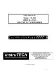
1-10
Performance Verification
Verifying resistance
Check resistance by connecting accurate resistance values to the Model 2010 and verifying
that its resistance readings are within the specified limits.
CAUTION
Do not apply more 1000V peak between INPUT HI and LO or more than
350V peak between SENSE HI and LO, or instrument damage could occur.
Follow these steps to verify resistance accuracy:
1.
Figure 1-5
Connections for
resistance verification
(10Ω-10MΩ ranges)
Using shielded 4-wire connections, connect the Model 2010 INPUT and SENSE jacks
to the calibrator as shown in Figure 1-5.
Sense HI
Model 2010
!
2000 MULTIMETER
Sense HI
5700A Calibrator
Input
HI Output
HI
R
Sense LO
Input Output
LO LO
Sense LO
Note : Use shielded low-thermal cables to
minimize noise. Enable or disable
calibrator external sense as indicated
in procedure.
2.
3.
4.
5.
Set the calibrator for 4-wire resistance with external sense on.
Select the Model 2010 4-wire resistance function by pressing the Ω4 key.
Set the Model 2010 for the 10Ω range, and make sure the FILTER is on. Set the
calibrator output to 0Ω, then enable Model 2010 REL.
Recalculate reading limits based on actual calibrator resistance values.