1
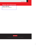
Disassembly
1.
2.
3.
5-5
Remove the cover from the instrument as explained in Case cover removal.
The resistors used to select the trigger link lines are located next to the Trigger Link
connector as shown in Figure 5-1. The “resistors” are actually solder beads that bridge
pc-board pads. If the factory default lines are selected, the solder beads will be located
at R270 (line 2, EXT TRIG) and R267 (line 1, VMC).
To change a trigger link line:
•
•
•
Use a hot air pencil to remove the appropriate solder bead.
Using a solder with OA-based flux, apply a solder bead to the appropriate resistor
location.
Replace the cover on the instrument.
Figure 5-1
Trigger link connectors
Mother Board
(view from top)
Rear Panel
Trigger Link
Connector
Trigger Link Lines
Solder
Line 1 = VMC (R267)
Bead
Line 2 = EXT TRIG (R270)
Line 3 = VMC (R266)
Line 4 = EXT TRIG (R268)
Line 5 = VMC (R265)
Line 6 = EXT TRIG (R269)
R269
R268
R270
R265
R267
R266
Motherboard removal
Perform the following steps to remove the motherboard. This procedure assumes that the case
cover is already removed.
1.
Remove the IEEE-488 and RS-232 fasteners.
The IEEE-488 and the RS-232 connectors each have two nuts that secure the connectors
to the rear panel. Remove these nuts.
2.
Remove the front/rear switch rod.
At the switch, place the edge of a flat-blade screw driver in the notch on the pushrod.
Gently twist the screw driver while pulling the rod from the shaft.
3.
Disconnect the front and rear input terminals.
You must disconnect these input terminal connections for both the front and rear inputs:
•
•
•
INPUT HI and LO
SENSE HI and LO
AMPS