1
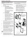
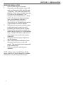
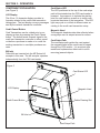
MC-CRX
Bill Acceptor Card Reader Combo
Operation & Service Manual
TABLE OF CONTENTS
SECTION 1: GENERAL INFORMATION
Introduction...........................................................4
Features...............................................................4
For Records..........................................................4
After Unpacking....................................................4
Naming Convention..............................................5
Dimensions & Specifications................................6
SECTION 2: INSTALLATION
Installing the CRX Card Reader on MC Series Bill
Acceptor...............................................................7
Installing the MC-CRX in the Equipment.............7
Verifying Installation.............................................8
SECTION 3: OPERATION
Component Explanation.......................................9
SECTION 4: MAINTENANCE
Routine Maintenance.........................................10
Cleaning.............................................................10
Procedure...........................................................10
SECTION 5: TROUBLESHOOTING
Introduction.........................................................11
Logic Troubleshooting........................................11
Card Reader Troubleshooting............................11
SECTION 6: PARTS LIST
Card Reader Assembly......................................12
3
SECTION 1: GENERAL INFORMATION
INTRODUCTION
This manual contains information on installing,
operating and maintaing Coinco’s MC-CRX Series Card Reader. The card reader decodes the
magnetic information from a mag stripe credit or
debit card and transmits card data to a transaction server. This manual is intended for owners,
route operators, and shop-level technicians as
a primary source of information. Taking time to
read this manual and becoming familiar with this
information will help you obtain the best performance from your Coinco card reader
NOTE: Please refer to the MC Series Bill Acceptors Operation & Service Manual for detailed
information on the MC Series bill acceptor.
FEATURES
•
•
•
•
•
•
•
Self-Clearing vertical swipe
Illuminated inlets on card and bill paths
Audible feedback for card swipe/cancel
High contrast dual line display
Flash programmable memory
Metal bezel and rugged design
Programmable acceptance of the
following: $1, $5, $10, $20, $50, $100;
Coupon capabilities
Credit or debit card acceptance
Installs easily in existing mountings
Self-diagnostics communicated via status
light
Built upon the flexible MC Series system
Manufactured and supported by Coinco
Made in the U.S.A.
•
•
•
•
•
•
FOR YOUR RECORDS
A label indicating the model number and serial
number of the card reader can be found on the
inside of the mask. The first four digits of the
serial number indicate when the unit was built,
which is also the beginning of the warranty period. The first two digits indicate the week of the
year and the third and fourth digits indicate the
year.
EXAMPLE: Serial number 0207000123 would
indicate the unit was built in the second week of
2007.
4
AFTER UNPACKING
After unpacking the unit, inspect for any possible
shipping damage. If the unit is damaged, notify
the shipping company immediately. Only the
co-signee (the person receiving the unit) can file
a claim against the carrier for shipping damage.
We recommend that you retain the original carton and packing materials to reuse if you need to
transport or ship the unit in the future.
If the card reader is being stored or used as a
spare, always keep it in its shipping carton when
not in use. This will keep it clean and offer the
best protection for the unit.
SECTION 1: GENERAL INFORMATION
NOTE: For more information on the generic version programming interface, please request Coinco
Publication # 926215 Rev. 2
5
SECTION 1: GENERAL INFORMATION
Dimensions & Specifications
Interface Connections
RS232 (USA Tech/Generic)
Pin 1 - NC
Pin 2 - TX (232)
Pin 3 - RX (232)
Pin 4 - NC
Pin 5 - Ground
Pin 6 - +5V
Pin 7 - NC
Pin 8 - NC
Pin 9 - NC
Power Requirements
CRX-U
5VDC + 10%; 0.15 A max current
draw RS232 serial interface to host,
9600 baud.
CRX-G
5VDC + 10%; 0.15 A max current
draw RS232 serial interface to host,
9600 baud.
Operating Temperature
0 F to 150 F
-18 C to 65 C
Storage Temperature
-22 F to 165 F
-30 F to 74 F
3.31
(84.1)
3.32
(84.3)
Relative Humidity
5% to 95% non-condensing
Physical Weight in Shipping Carton
MC Series
4.2 lbs.
CRX Retrofit
1.5 lbs.
7.68
(195.2)
3.28
(83.4)
6.77
(172.1)
.20
(5.1)
9.37
(238)
5.20
(132.0)
4.69
(119.3)
.68
2.00
(50.8) (17.2)
3.74
(95.1)
6
2.23
(56.8)
4.23
(107.5)
2.09
(53.0)
2.28
(57.9)
3.01
(76.5)
Figure 1
SECTION 2: INSTALLATION
INSTALLING THE CRX CARD READER ON
MC SERIES BILL ACCEPTOR (for retrofitting a card
reader only)
1.
2.
3.
4.
5.
6.
Verify the MC Series bill acceptor is
functioning properly before installing the
CRX mask.
For the Standard Bezel:
•
Using a Phillips screwdriver,
remove the 4 screws that secure
the MC Series bezel to the mounting frame and mainframe (See Figure 2).
•
With the bezel out of the way, un
plug the ground wire connected to
the mounting frame.
•
Proceed to Step 3.
For the Slimline Bezel:
•
Using a Phillips screwdriver,
remove the 3 screws that secure
the MC Series bezel to the mounting frame (See Figure 2).
•
With the bezel out of the way,
unplug the ground wire connected
to the mounting frame.
•
Remove the four screws that attach
the mounting frame to the mainframe of the MC Series bill
acceptor.
Place the new mounting frame from the
CRX kit onto the bill acceptor mainframe.
Verify that the plastic insulation is facing
down against the mainframe.
Be sure to attach the bill acceptor ground
wire to the mounting frame.
Route CRX Card Reader harness (under
the mounting frame) to the same side as
the existing MC harness. Ensure the CRX
harness is aligned with the cutout in the
new mounting frame.
Lower the CRX Card Reader onto the
mounting frame and reattach using the
screws from Step 2. Make sure the
mask mounts flush to the mounting frame.
INSTALLING THE MC-CRX IN THE EQUIPMENT
1.
Disconnect the machine’s power.
2.
Install the MC-CRX unit into the mounting opening of the machine using
the appropriate hardware (not included).
NOTE: Should additional mounting hardware by
required, please contact your local Coinco office
or machine manufacturer.
3.
To ensure proper operation, the MC Series
mounting suface must be connected to the
equipment’s earth ground.
4.
Connect the MC Series MDB bill validator
interface harness to the equipment’s
controller and coin changer (as applicable). Ensure that the credit card
transaction controller unit is properly
installed for your MC-CRX and
then connect the card reader interface
harness to the appropriate port.
MC-CRX Card
Reader Mask
Ground wire
attach point
MC-CRX
Mounting
Frame
NOTE: The mounting
frame supplied with your
MC-CRX should be used
to replace the original
mounting frame.
CRX Harness
Routing Notch
Slimeline
Bezel
Mounting
Frame
Main Frame
Mounting
Frame
Standard Bezel
Figure 2
7
SECTION 2: INSTALLATION
VERIFYING INSTALLATION
1.
Restore power the the equipment.
2.
On power up the bill acceptor motors will
cycle, and the green LEDs will blink after
15 seconds. The card swipe status LED
will blink 5 times with an audible beep and
LCD will turn on and display “Coin
Acceptors” and software version. Check
LCD for the expected startup message
from your transaction controller. If
this sequence of events does not
occur, refer to the Troubleshooting section
of the Operation & Service Manual.
3.
With the price set below one dollar, swipe
a valid credit card or other test card
provided by a backend service supplier.
4.
Verify that the card reader accepted the
credit card by checking for a single audible
beep. The MC-CRX card reader will emit
three beeps on an invalid card swipe or
credit card.
5.
Verify that credit had been established
with the machine.
6.
After credit has been established, press
the cancel credit button on the card
reader. This should also be accompanied
by an audible beep.
7.
Verify the machine credit has been
canceled.
NOTE: Please refer to the MC Series Bill Acceptor Operation & Service Manual for detailed
information on the MC Series Bill Acceptor.
8
SECTION 3: OPERATION
COMPONENT EXPLANATION
(see Figure 3)
LCD Display
This 2 line, 16 character display provides information related to the credit card transaction
taking place. The text display conveys messages
sent by the network transaction controller.
Credit Cancel Button
Card Transactions can be voided prior to purchasing an item by pressing the Credit Cancel
button. The button sends a cancel signal to the
credit card transaction controller to either cancel
out before a purchase is made or to curtail the
existing transaction in a multiple purchase scenario.
Bill Inlet
Dollar bills are inserted into the MC Series bill
acceptor in this area. The bill acceptor operates
independently from the CRX card reader.
Card Status LED
The LED positioned at the top of the card swipe
path is illuminated when the CRX card reader is
powered. Its purpose is to indicate the starting
point for card insertion as well as to visibly communicate the status of the transaction. This LED
light may cycle on or blink at different rates according to the credit card transaction setup.
Magnetic Head
The magnetic head decodes data collected when
a mag stripe card is swiped across its surface.
Card Swipe Path
The card swipe path guides the card against
the magnetic head as the credit card is swiped
through the CRX module. It is a vertical style
reader and implements a debris slot to aid in
removing jammed objects.
Figure 3
Card Status LED
LCD Display
Magnetic Head
Credit Cancel Button
Debris Clearing Slot
Bill Inlet
Card Swipe Path
9
SECTION 4: MAINTENANCE
ROUTINE MAINTENANCE
Routine maintenance will improve the performance and extend the working life of the MCCRX card reader. Frequency of maintenance
will depend on the environment and number of
transactions. For normal environments, cleaning
is recommended every 6 months.
CLEANING
The MC-CRX card reader is manufactured from
metal and high-quality plastics, which should
only be cleaned with a soft bristle brush or cloth
dampened with warm water and a mild detergent
solution, if necessary. Dust can be removed using a soft brush or blown out using compressed
air. (refer to Figures 2 & 3)
PROCEDURE
1.
Disconnect the power before cleaning.
2.
Mix warm water and mild detergent.
3.
Dampen the brush or cloth with solution
and wipe the outside of the card reader.
4.
Rinse the cloth with clean water and wipe
the previously cleaned area to rinse off
solution.
5.
To clean the card slot, dampen a cloth with
the detergent solution and pull the towel
through the card slot.
6.
Wait until the unit is completely dry to
restore power and verify the unit is
functioning properly.
WARNING: Never submerge the unit in water
and avoid getting water on the circuit board of the
reader. Do not use petroleum-based cleaners,
solvents, steel wool, scouring pads, or stiff bristle
brushes for cleaning. Do not spray any type of
lubricant on any part of the card reader or the MC
Series bill acceptor.
10
SECTION 5: TROUBLESHOOTING
INTRODUCTION
The troubleshooting guide on this page is intended to help locate problems within the MC-CRX. If
a unit cannot be repaired by the following guide,
return the unit to the nearest Coinco Service Center for repair along with a complete description of
the problem you are experiencing.
•
Next check the LCD for a text message,
if it reads a string beginning with “CAI”,
it means that card reader has been
powered up and is receiving no communication from the machine. In this case,
check the setup of the network
transaction controller.
Logic troubleshooting mimimizes the time spent
in removing and replacing parts that are not
defective. Some failures are caused by minor
problems such as dirt, or loose/faulty connections. Please check the following before replacing any parts:
•
If the LCD display has a different error text
message, refer to the credit card transaction controller manual or troubleshooting
guide for proper interpretation.
•
Verify the transaction server is operating
properly
•
Clean any dirt or dust from the card swipe
path
•
Verify all harness connectors are inserted
properly and that connector pins are not
bent or broken
•
All wires are properly secured
•
Verify the machine controller is capable for
communicating to a card reader
•
Machine is not disabling card acceptance
If the unit cannot be repaired by these methods,
return the unit to the nearest Coinco Service Center for repair along with a complete description of
the problem you are having.
NOTE: Please refer to the MC Series Acceptor
Operation and Service Manual for detailed information on the MC Series Bill Acceptor.
CARD READER TROUBLESHOOTING
If the above has not resolved the problem, please
check the following.
•
Verify that the card reader is being
powered by the transaction controller by
checking the LCD display. If it is powered,
the LCD screen will glow green. Refer to
Figure 3 to locate the card swipe status
LED.
•
Verify that on power up, the card reader
has properly powered up by checking for
the card swipe status LED blinks
accompanied by an audible beep.
11
SECTION 6: PARTS LIST
2
3
1
Item #
Part #
Description
Quantity
409931
1
4
2
303317
MC72-CRX-U
MC7200 Card Reader (USA Tech)
MC72-CRX-G
MC7200 Card Reader (Generic)
MC26-CRX-U
MC2600 Card Reader (USA Tech)
MC26-CRX-G
MC2600 Card Reader (Generic)
Front Mask Screws
3
met/289
Mounting Frame
1
4
926326
Carton Insert (Not Shown)
1
1
CRX Card
Reader
Retrofit
Kits
409932
409934
409935
12
1
1
1
NOTE: Kits MC26-CRX-U, MC26-CRX-G, MC72-CRX-U and MC72-CRX-G contain
items 1, 2, 3, & 4.
Coin Acceptors, Inc USA
300 Hunter Avenue
St. Louis, MO 63124
800.325.2646
Coin Acceptors, Inc. Canada
1-435 Four Valley Dr.
Concord (Toronto), Ontario
l4K 5X5 Canada
800.387.9300
email: [email protected]
www.coinco.com
Coinco Publication No. 927991