1
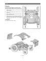
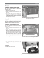
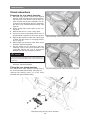
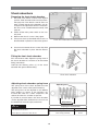
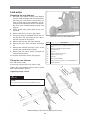
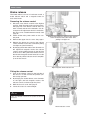
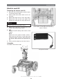
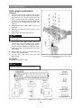
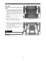
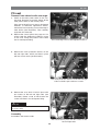
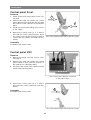
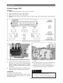
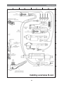
Link arms Link arms Removing the rear link arm 1. Raise the seat; electric seat lift to the highest position; fixed seat tube to the service position. See page 28. If the electric seat lift does not work normally because the batteries are discharged or the adjustment device is defective, the seat can be raised/lowered manually. See page 26. 2. Switch off the main power switch on the control panel. 3. Remove the chassis covers. See page 8. 4. Lift up and chock up the wheelchair chassis so that the front and rear wheel on the side in question are free of the ground. External screws for the parallel strut. 5. Remove the front link arm. See page 20. Item 6. Remove the rear shock absorber. See page 18. Description 1 Socket head cap screw ISO 4762 M6x70 8.8 Fe/Zn 5 C1 2 Washer, ISO 7089 6 200 HV Fe/Zn 5 C1(6.4x12x1.6) 3 Spacer 4 Support wheel incl. bracket 5 Drive motor incl. gear 6 Link arm 7 O-ring, 24.2x3 EPDM Fitting the rear link arm 8 Spacer washer, 28 Fe/Zn 12 C1 (DB 28x40x1.5) Fit in the reverse order. 9 Circlip, Ø 28 mm 7. Remove the external mounting screws of the parallel strut (see illustration above). 8. Remove the link arm by pulling it straight out (see illustration below). For removal of the drive motor, see page 25. If necessary, replace the o-ring and/or circlip. Tighten the screw holding the link arms in place with a dynamometric wrench. 7 8 9 Tightening torque: 15 Nm. NB Lubricate the o-ring with grease friction brake, Item: 1820405. Do not use an impact wrench for the tightening torque. 2 1 6 5 4 3 Removal/fitting of the rear link arm and drive motor. 21