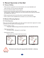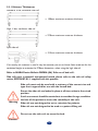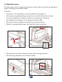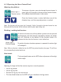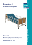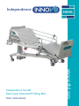
1
Independence
User Instructions
www.sidhil.com
Independence Innov8
Electrically Operated Profiling Bed
Section
Title
1
1.1
1.2
2
2.1
2.2
3
4
5
5.1
5.2
5.2.1
5.2.2
5.3
5.3.1
5.3.2
5.3.3
5.4
5.5
5.6
5.7
6
6.1
6.1.1
6.1.2
6.2
6.3
7
7.1
7.2
8
8.1
8.2
8.3
9
9.1
9.2
10
11
Introduction
Features
Warning and Cautions
Clinical Use
Typical Use
Risk Assessment
Symbol Definition
Installation
Manual Operation of the Bed
General Safety
Brake & Steer System
Pedal Operation
Moving the Bed
Side Rails
Mattress Thicknesses
Operating the Side Rails
Operating the Split Side Rails
Bed Extension
Bed Stripper
Emergency CPR Function – Manual
Bed Ends
Electrical Operation of the Bed
Nurse Control Panel
Nurse Control Panel Features
Operating the Nurse Control Panel
Patient Handset
Night Pack
Decontamination
Biocote
Cleaning & Disinfection Guidelines
Maintenance
Fault Finding
Resetting / Intialising the Electrical System
General Maintenance
Specification
Bed Data
Electrical Data
Accessories
Warranty
Page
1
1
1
2
2
2
3
4
5
5
5
5
6
6
7
8
9
10
11
12
13
14
14
14
15
18
19
20
20
20
21
22
22
23
24
24
25
25
26
1. Introduction
Thank you for purchasing A Sidhil Independence Innov8 Bed. This user manual should be
read carefully before operating the bed. Please ensure that you understand all instructions,
if you have any questions concerning the operation or maintenance of the bed please
contact Sidhil Ltd.
1.1 Features
•
•
•
•
•
•
•
•
•
•
•
•
•
•
Electrically operated backrest, height and knee break angle
Auto regressing backrest
Infinitely variable electrically operated head and foot down tilt
(Trendelenburg & reverse Trendelenburg)
Auto contour – simultaneous adjustment of the backrest and knee-break
Auto cardiac chair position
Battery backup
Patient handset and nurse control panel with integral function lockout
Removable head and foot ends
Removable plastic mattress platform panels
Mattress platform extension
Pull out bed stripper
Integral side rails*
X-ray translucent backrest with cassette tray*
Oxygen cylinder carrier*
* Feature availability is dependent on the bed model
1.2 Warnings and Cautions
Warnings in this user manual highlight potential hazards that if disregarded could lead to
injury or death.
Cautions in this user manual highlight potential hazards that if disregarded could lead to
equipment damage or failure.
1
2. Clinical Use
2.1 Typical Use
The Innov8 bed range covers every need from a utility ward bed to high dependency,
where patients whose clinical requirements and situation of care require positioning with
minimal handling.
At the carer’s discretion patients can use the controls to adjust the bed to their preferred
position.
2.2 Risk Assessment
Before a patient uses the bed a risk assessment must be performed on a patient by patient
basis. The risk assessment should include, but is not limited to:
•
•
•
•
Entrapment
Falling out of the bed
Small children (and adults)
Patients with learning difficulties
The safe working load of the bed is:
The maximum user weight of the bed is:
255kg (40 stone)
220kg (35 stone)
Bed functions must be locked out if there is any doubt about the
ability of the patient operating the bed safely.
Warning
Misused electrical equipment can be hazardous.
Accessories that have not been approved or designed for use with the
bed should not be used.
Electrically operated beds should not be used in the presence of
Warning flammable gasses.
Electrically operated beds should not be used in operating theatres.
Ensure cables are kept away from moving parts of the bed, to avoid
damage to the bed and / or cabling.
Caution
2
3. Symbol Definition
The following symbols are found on the bed:
Warning
Refer to user guide
Safe working load
Maximum user weight
Place of manufacture
W.E.E.E Label
(Do not disgard in general waste, follow local
recycling policy)
3
4. Installation
Prior to operating the bed for the first time the following simple checks must be
performed:
•
•
•
•
Ensure the bed (and all accessories) is at room temperature
Ensure the bed has been cleaned and disinfected (page 19)
Connect the mains cable to an appropriate mains socket outlet
Using the nurse control panel, raise the mattress platform to its
maximum height to ensure the bed is level (page 14)
If the electrical functions are not active it will be for one of two reasons:
1. Functions have been locked out on the nurse control panel, see page 14 for activation.
2. The electrical system needs initialising, see page 21 for the procedure.
Ensure the orange coiled mains cable is not in tension when connected
to the mains supply.
Ensure that cables and handsets are clear of all moving parts to
prevent damage to the electrical components.
Warning
Special care should be taken when fitting an air mattress to the bed as
incorrect fitting could damage the bed.
4
5. Manual Operation of the Bed
5.1 General Safety
• When the bed is operated, ensure that obstacles such as over-bed tables and
other furniture are not causing an obstruction.
• Ensure the electrical cables are not in tension.
• Ensure that any mattresses used are of the correct size and type and have been
fitted correctly. A range of suitable pressure relieving and pressure reducing mattresses
are available from Sidhil Ltd.
• Before operating the bed ensure the patient is positioned appropriately.
• When a patient is left unattended ensure the bed is set at its minimum height.
5.2 Brake & Steering System
5.2.1 Pedal Operation
There are two linked brake pedals at the foot end of the bed which operate the castors
simultaneously. Each pedal has a red and green end.
• Green end down (steer):
One castor is locked, allowing the bed to be steered from the head end of the bed.
• Pedal horizontal (free):
No locked castors, allowing all to swivel freely.
• Red end down (brake):
Three castors are locked, the bed cannot move.
Steer
Free
Brake
The brake must always be engaged when the bed is stationary.
Warning
5
5.2.2 Moving the Bed
Before moving the bed the following checks must be performed:
•
•
•
•
Side rails must be raised if there is a patient in the bed, to minimise the risk of falling.
The platform must be horizontal.
The platform must be raised/lowered to a suitable height for pushing.
The mains lead must be unplugged and stored on the cable tidy hooks
If the bed is to be pushed up/down a slope it is advised that two
people move the bed, with one person at each end.
Warning
If the bed is to be pushed with a heavy load it should be assessed
whether or not two people should move the bed, this is
dependent on the situation and load on the bed.
5.3 Side Rails
The Innov8 bed range can be specified with three different types of side rail, this is
to provide the optimum mattress/side rail combination for both foam and air mattresses
of varying thicknesses. When specifying a mattress and side rail combination a clinical
assessment of the patient’s needs must be carried out in line with the local policy.
6
5.3.1 Mattress Thicknesses
Standard, 3 bar, cantilever side rail
= 158mm maximum mattress thickness
High, 4 bar, cantilever side rail
= 270mm maximum mattress thickness
Split side rail
= 152mm maximum mattress thickness
If an overlay air mattress is used it may be necessary to use a thinner foam mattress for the
combined height to maintain the 270mm dimension, when using the high side rail.
Refer to MHRA Device Bulletin DB2006 (06) ‘Safe use of bed rails’.
Side rails pose a potential entrapment hazard, please refer to the side rail safety
notice, SR/PSN 01/01/1, supplied with this product.
Side rails must only be used with a mattress of the correct size and
type that is approved for use with the Innov8 bed.
Ensure the side rails are locked in place at all times when in the raised
position.
A risk assessment should be carried out to consider the age, condition
and size of the patient to assess the suitability of side rails.
Warning
Side rails are not designed to act as restraints for patients.
Side rails are not designed to be used as a patient lifting aid.
Do not use the side rails to move the bed.
Caution
7
5.3.2 Operating the Cantilever Side Rails
To lower:
Hold the top rail and pull out the release plunger. Gently lower the side rail towards the
foot end of the bed.
To raise:
Hold the top rail and lift the side rail until it locks into the vertical position.
Ensure the side rail release plunger is fully engaged when the side
rails are in the raised position.
Warning
When operating the side rails ensure they are free from obstructions,
to prevent injury/entrapment.
When lowering do not drop the rail, damaged could be caused.
Caution
8
5.3.3 Operating the split side rails
To lower:
Support the side rail at the top of the forming and pull the green release handle. Gently
lower the side rail towards the floor and release once it has travelled more than 90°
through its range of movement.
To raise:
Hold the side rail at any point along the length of the forming, raise component until the
lock pins engage into position.
Ensure the side rail lock pins have fully engaged when the side rails
are in the raised position.
When operating the side rails ensure they are free from
Warning
obstructions, to prevent injury/entrapment.
When lowering do not drop the rail, as damage could be caused.
Caution
9
5.4 Bed Extension
The bed comes with an integral bed extension which allows the bed to be adjusted in
length, according to the patients needs.
To extend:
• If the bed is in tilt the platform must be levelled first (see page 15).
• Pull out the spring loaded plunger located on the side of the bed near the foot
end, whilst holding out rotate by a quarter turn (the plunger should stay
out). Repeat for the plunger on the opposite side of the bed.
• Pull out the mattress platform extension to its maximum extent.
• Rotate the spring loaded plungers until they lock back into position.
• Press down on the catch located at the foot end of the leg extension.
• Pull out the leg extension to its maximum extent.
10
To retract:
• Push in the leg extension until it re-engages with the catch.
• Pull out the spring loaded plunger located on the side of the bed near the foot end,
whilst holding out rotate by a quarter turn (the plunger should stay out). Repeat for the
plunger on the opposite side of the bed.
• Push the mattress platform extension fully in.
• Rotate the spring loaded plungers until they lock back into position.
Never pull the leg extension out without the mattress platform
extension pulled out.
Always fit a mattress extension block when the platform is extended.
Warning
Always ensure the extension is locked in position, both in the extended
& retracted state.
5.5 Bed Stripper
An integral extending bed stripper is incorporated into the foot end of the bed to assist
with linen changing procedures.
To use the bed stripper pull it out to its full extent.
After use, push the bed stripper fully in.
The safe working load of the bed stripper is 20kg.
Warning
11
5.6 Emergency CPR Function - Manual
The backrest and knee break can be levelled simultaneously via the manual CPR handles
located on both sides of the bed.
To flatten the platform in an emergency, pull one of the red handles outwards. The
backrest and knee break will drop into a flattened state.
Note: The platform will not level itself or change height when the manual handles are pulled,
this function is only available with the electrical CPR function.
The backrest and knee break may fall quickly, ensure that
limbs and equipment are clear.
Warning
12
5.7 Bed Ends
The bed has plastic end panels which are easily removable, allowing for fast patient access.
To remove, hold the panel with both hands and lift squarely.
13
6. Electrical Operation of the Bed
6.1 Nurse Control Panel
The nurse control panel (NCP) controls all bed functionality; it is to be used only by the
carer. The NCP is designed to be stored on the end of the bed by clipping it over the bed
end panel.
6.1.1 Nurse Control Panel Features
Backrest
Platform
height
Auto contour
Knee
break
Tilt
Cardiac
chair
Direction buttons
Function lock button
CPR button
14
6.1.2 Operating the Nurse Control Panel
Adjusting the platform:
Green light =
Function active
To activate a function, press the desired function button. A
green light will illuminate at the top of the function button,
this indicates that the function is now active.
Once the function button is active hold down one of the
direction keys, until the required position is reached.
Note: The function will stay active for 5 seconds. If after 5 seconds a direction button has not
been pressed the function will de-activate and the green light will go out.
Disabling / enabling bed functions:
To lockout a function one of the padlock symbols must be pressed
simultaneously with the function required for lockout. An amber
light will illuminate at the bottom of the function button, this
indicates the fact that the function is now locked out.
Amber light =
Function locked
To unlock a function the above process is repeated, the amber light
will extinguish.
Note: When a function is locked out on the NCP, the patient handset (see page 17) will have
the corresponding function locked out.
Knee break:
The knee break button on the NCP allows adjustment of the thigh
section angle.
Adjusting the height of the foot section requires a manual operation:
•
•
•
•
Lift the leg section.
Lift the leg stay bar.
Position the leg stay into the channel.
The knee break button on the NCP will now raise/lower the leg section.
15
Leg section height adjustment
Thigh section angle adjustment
Auto contour:
When the auto contour button is pressed both the backrest and
knee break functions operate together.
Note: The operation of the knee break section will vary dependent on
the position of the leg stay bar as detailed above.
Note: If the backrest or knee break are locked out this will
automatically disable the auto contour function.
Tilt:
Head down tilt (Trendelenburg) and foot down tilt can be applied
using the nurse control panel.
When in tilt, in order to level the bed the opposite direction button
should be pressed and held until the bed stops, the platform will
now be level (Note: it may be necessary to re-activate the tilt
function).
To continue tilting the bed in the opposite direction, re-press the
same direction button again and hold until the desired angle is
reached.
16
When the bed is put into head down tilt there must be sufficient
space behind the bed to ensure the head board and/or any ancillary
equipment cannot clash with the wall.
Caution
Cardiac Chair:
Green lights =
Function active
The bed can be automatically profiled into a cardiac chair position,
where the platform is automatically profiled into the auto contour
position and then moves into foot down tilt.
When the auto contour and tilt buttons are pressed within 5
seconds of each other, this automatically enables the cardiac chair
function. Pressing either one of the two ‘up’ buttons orientates the
bed into the cardiac chair position.
Pressing either one of the two ‘down’ buttons takes the bed out of
cardiac chair and levels the platform.
Electrical CPR:
Pressing the CPR button automatically levels, flattens and lowers
the platform, once the platform is at its minimum height it then
drives up to maximum height. Regardless of position the backrest
always lowers first (if raised), so that it is flat in the quickest
possible time.
Note: Pressing the CPR function overrides all locked out functions.
The mechanical CPR function will flatten the platform quicker than
the electrical CPR, but will not level or lower the platform.
Warning
Mains Power Indicator:
The nurse control panel has a mains power light in the top left
corner. If it is not lit amber, the bed is either unplugged or has a
fault (see page 21).
17
Battery Indicator:
The nurse control panel has a battery light that shows when the
battery is charging.
Note: It does not indicate when the bed is being run off battery power.
When the bed is running off battery power and the batteries are
almost flat an audible alarm will be heard when a handset button is
pressed.
The bed is not designed to run off battery power for long periods and
should always be plugged into the mains supply during normal use.
Caution
6.2 Patient Handset
The patient handset is designed to give limited control to the
occupant. It allows control of:
Backrest angle
Platform height
Auto contour (backrest and knee break profiled together)
Note: If functions have been locked out on the nurse control panel the
same functions will be locked out on the patient handset.
18
6.3 Night Pack (Optional accessory)
Along with the functions of the standard patient handset, the night
pack handset is back lit and controls an under bed light.
When any button on the handset is pressed all functions light up
and stay lit whilst the handset is in use or for 10 seconds if inactive.
When the under bed light button is pressed it operates a light on
both sides of the platform, providing a small pool of light either side
of the bed.
Under bed light button
19
7. Decontamination
7.1
Biocote
Infection control and routine cleaning must be carried out in accordance with your local
Infection control policy or regulatory body.
The bed comes with an antibacterial additive incorporated into the
powder coated metalwork. Biocote® inhibits the growth of bacteria
on the surface of the bed frame. It is effective against a wide range of
both gram positive and negative bacteria as well as fungi. Examples of
bacteria that Biocote® is resistant to include:
•
•
•
•
•
•
Bacillus Subtilis
Staphylococcus Aureus (MRSA)
Escerichia Coli 0157
Streptococcus Faecalis
Salmonella Enteritides
Listeria Monocytogenes
Biocote® is an aid to keeping your bed infection free but it does not
substitute the need for the bed to be cleaned at regular intervals.
Warning
7.2
Cleaning & Disinfection Guidelines
Always disconnect the bed from the main power supply prior to
cleaning.
Warning
To aid cleaning, the plastic bed ends and mattress platform panels can be removed. It is also
advisable to remove any accessories that are fastened to the bed.
These instructions apply to all accessories apart from soft products (e.g. mattresses).
20
•
All surfaces to be wiped down with a disposable soft cloth moistened with a
mild detergent and diluted in warm water (40°C).
•
The bed should be cleaned by starting with the cleanest parts of the bed and
systematically moving to the dirtiest parts. Extra care should be taken around
areas where excess dirt or dust may gather.
•
The cloth should be changed during the cleaning process if it becomes soiled.
•
Rinse down with clean water to remove detergent residue.
•
Wipe surfaces down with 1,000 parts per million chlorine solution (0.1%)
•
Dry off with a paper towel.
•
Always ensure the cleaned parts are allowed to dry before putting the mattress
back in place.
Note: If any of the 3 stages stated above (detergent, rinse down & chlorine solution) are
omitted or combined it will reduce the effectiveness of the clean.
In cases of blood spills or other bodily fluids it is recommended that a chlorine solution of
10,000 parts per million (1%) is used instead.
Note: The use of neat bleach or similar surface cleaners are not recommended as damage may
be caused to the cleaned surfaces.
Alternatively:
Sidhil recommend the use of Chlor-clean tablets. Follow the manufacturer’s instructions
for concentration guidelines and instructions for use.
Refer to the Sidhil infection control policy, copies are available from Sidhil Ltd. Contact
details can be found on the back of this booklet.
8. Maintenance
Only authorised service personnel or Sidhil service engineers should carry out repairs or
service activities. Failure to do so may result in the manufacturer’s warranty becoming
void. The bed must be serviced once yearly, as a minimum. Sidhil also recommends
that the carer performs frequent visual and operational inspections. If there are any signs
of damage or the bed is not performing as it should withdraw it from service until the bed
has been repaired and is fit for use again.
Periodically check to ensure that:
The bed operates as per its intended purpose.
All parts are present.
All fixtures and fittings are tight.
The frame is mechanically sound.
No parts show signs of excessive wear.
The bed is cleaned following the guidelines in this user guide.
21
8.1 Fault Finding
Listed below are a set of electrical faults that may occur within the service life of the bed. If a
fault does occur please try the following suggestions, as these may help in diagnosing the fault.
Fault
Possible Cause
Remedy
Functions locked out on NCP Unlock function(s)
Electrical function(s)
do not work
Mains lead not plugged into
the control box or wall and
batteries flat
Fuse has blown in the mains
plug
Actuator/handset leads not
plugged in
Electrical functions
working slowly
Check to see if the mains
power indicator on the NCP is
lit and the mains lead is plugged
in at both ends
Check to see if the mains
power indicator on the NCP is
lit, if not replace fuse
Check plug connections
Damage to mains cable,
actuator cable or handset
cables
Turn off at the mains and
contact the approved service
engineer
Reset System (see section 8.2)
Mains lead not plugged into
the control box and working
off battery backup
Mains lead not plugged into
the control box and working
off battery backup
Heavy load on the bed
The bed will not level
The electrical system has
become out of sync
Reset the electrical system as
stated below
8.2 Resetting/ Initialising the Electrical System
Very occasionally the bed may need to be reset. To reset the bed:
• Press both hi/low buttons on the patient handset together.
• An audible alarm will be heard for approximately 5 seconds.
• When the alarm stops sounding the bed must be driven up to its
maximum height.
• When at maximum height re-press the up button again (to ensure both
actuators are at maximum height).
• The bed is now reset and will work correctly.
22
8.3 General Maintenance
Sidhil recommend that the following maintenance procedure is performed every 12
months.
Always disconnect the bed from the main power supply prior to
performing any maintenance procedures.
Warning
•
•
•
•
•
•
•
•
•
•
•
•
•
•
•
•
•
•
The bed operates as per its intended purpose.
All parts are present.
The frame is mechanically sound.
All welds are present and show no signs of cracking/failure.
No parts show signs of excessive wear.
The electrical housings are not cracked/damaged.
Check that all electrical cables are in good condition.
Check that the bed works correctly when run off battery back up.
Check that the mains cable and plug are in good condition, if either is
damaged it must be replaced with a complete assembly, the plug must never
be re-wired.
Check that all nuts, bolts and fasteners are tight and that none are missing or
incomplete.
Check the manual CPR mechanism works correctly.
Check the bed extension extends and retracts correctly and locks/disengages
in both positions.
Check the leg extension extends correctly and locks in the retracted position.
Check the bed stripper extends and retracts smoothly.
Put the castor pedal into the brake position (see page 5). Push the bed with a
normal level of force, ensure the bed does not move.
Put the castor pedal into the steer position (see page 5). Push the bed and
check that the bed runs straight.
Raise and lower the safety sides. Check that they move smoothly.
Check that the lock on the safety sides automatically engages when raised.
For more detailed service information please refer to the service manual. Copies are
available from Sidhil Ltd. Contact details can be found on the back of this booklet.
23
9. Specification
9.1 Bed Data
Overall length
2127mm
Integral length extension
200mm
Overall width
1016mm
Mattress platform height
(125mm single castors)
415mm – 815mm
Under bed clearance
207mm
Mattress platform length
1950mm
Mattress platform width
900mm
Head down tilt
0 - 12°
Foot down tilt
0 - 12°
Mattress platform angles (max):
73°
19°
32°
Safe working load
255kg (40 stone)
Maximum user weight
220kg (35 stone)
Product weight (approx.)
150kg
24
9.2 Electrical Data
Voltage in
Current in
Voltage out
Current out
Duty rating
Safety standards
230V, 50/60Hz.
2A max.
24V
8A max.
10%
max 2/18min. (at I out = 3,8A)
BS EN 60601-1: 2006
BS EN 60601-2-38: 1997
Electrical shock protection
Class I, Type B
EMC
BS EN 60601-1-2:2002
Liquid ingress protection
IP54*
Battery backup
2 x 12V sealed rechargeable lead/acid
batteries
The electrical system is only suitable for use when:
Ambient temperature
Humidity
+5° to +40°C
20% - 90% at 30°C
* Bed can be specified with IP66
10. Accessories
A full range of accessories, including mattresses, are available from Sidhil Ltd.
Lifting pole
IV pole
Traction – balkan beam
Traction – foot end
Monitor shelf
Oxygen cylinder carrier
Mattresses
INNOV8/LP
INNOV8/DP
INNOV8/TBB
INNOV8/TFE
INNOV8/MS
INNOV8/OC
Various*
* For further information regarding suitable mattresses please contact Sidhil customer
services. Contact details can be found on the back of this booklet.
25
11. Warranty
Sidhil Ltd guarantees this product is free from defects in material and workmanship
under normal use for 3 years (1 year full parts and labour, 2 further years parts only)
from the date of purchase from Sidhil Ltd and its subsidiary companies or its authorised
dealers. All implied warranties, including but not limited to those implied warranties of
fitness and merchantability, are limited in the total duration of three years from date of
purchase. Proof of purchase must be presented with any claim. Except as provided
herein, Sidhil Ltd, product warranty does not cover damage caused by misuse or abuse,
accident, the attachment of any unauthorised accessory, alteration to the product, or any
other conditions whatsoever that are beyond the control of Sidhil Ltd. Sidhil Ltd and its
subsidiary companies shall have no liability or responsibility to customer or any other
person or entity with respect to any liability, loss or damage caused direct or indirectly
by use or performance of the product or arising out of any breach of this warranty,
including but not limited to any damages resulting from inconvenience, loss of time,
property, revenue, or profit or any indirect, special, incidental or consequential damages,
even if Sidhil Ltd or their subsidiary companies or authorised dealers has been advised of
the possibility of such damages.
In the event of a product defect during the warranty period you should contact Sidhil Ltd
or their authorised dealer who will at its option unless otherwise provided by law; a)
correct the defect by product repair without charge for parts and labour b) replace the
product with one of the same or similar design or c) refund the purchase price. All
replaced parts and products on which refund is made become the property of Sidhil Ltd.
New or reconditioned parts and products may be used in the performance of warranty
service. Repaired or replaced parts and products are warranted for the remainder of the
original warranty period. You will be charged for repair or replacement of the product
made after the expiration of the warranty period.
This warranty does not cover; a) damage or failure by or attributes to acts of God,
abuse, accident, misuse, improper or abnormal usage, failure to follow instructions,
improper installation or maintenance, alterations, lightning or other incidence of excess
voltage or current, b) any repairs other than those provided by a Sidhil Ltd authorised
technician, c) consumables such as fuses, d) cosmetic damage, e) transportation, shipping
or insurance costs or f) costs of product removal, installation setup service adjustment or
re-installation.
This limited 3 year warranty gives you specific legal rights and you may also have other
rights.
Sidhil Ltd cannot be held responsible for any injury or incident which relates to the use
of the Innov8 bed range in conjunction with accessories manufactured by companies
other than Sidhil Ltd.
All products carry the CE mark in accordance with EC Directive on Medical Devices
(93/42/EEC).
Sidhil has a policy of continual product improvement and reserves the right to amend
specifications covered in this brochure.
No part of this brochure may be reproduced without the written approval of Sidhil Ltd.
26
Tel: 01422 233000 Fax: 01422 233010
Email: [email protected] www.sidhil.com
Sidhil Business Park, Holmfield, Halifax, HX2 9TN
A member of the Siddall & Hilton Ltd. Group of Companies
(93/42/EEC)
Certificate No. FM14550
INSTRUC/INNOV8 - APR 12, REV07