1
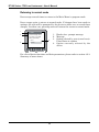
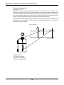
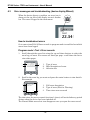
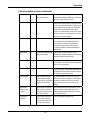
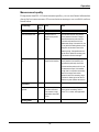
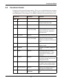
Operation Gas r function C.1.15.0 In solid applications where there is a lot of dust in the air above the product it may be necessary incease the value of Gas r slightly to improve accuracy. Please contact our local service centers for further assistance. For all other applications use the the default value of 1. Use this function if the probe is entirely coated with a regular layer of residue or dust from the product. Thresholds As explained in the measuring principle, DR7100 emits a low-power electromagnetic signal that reflects back from the the product surface and any other protuding objects in the tank. These signals are converted to voltage amplitudes by the signal converter. Reflections from the internal tank components are known as parasite or interference signals. A method of filtering out these signals, called thresholds, permits reflections under a given voltage amplitude to be ignored and measurements to be made correctly. As voltage amplitude also decreases over distance, this threshold decreases according to a mathematical formula. The first return signal over the threshold is identified as the product surface. Once identified, the signal converter has to process the signal: it amplifies the signal (defined by levels of Gain: 0 to 3) to use it for measurement purposes. A strong return signal will be given a Gain 0 or low amplification, while a weak signal will be given Gain 3 or high amplification. Normally the signal converter will automatically identify the signals to be measured and adjust the Gain to follow the same signal along the length of the probe as the tank is filled or emptied. However, if there are large and/or too many other objects in the tank and the signal converter has problems following the signal then the threshold may need adjusting manually to suit the installation. The DR7100 allows three thresholds to be modified manually: Menu item C.1.16.0 level: for identifying the top product surface, Menu item C.1.17.0 interface: for identifying the interface when there is more than one product in the tank and Menu item C.1.18.0 probe end: for identifying the end of the probe (important for TBF mode) In order for the user to identify the correct signal, the signal screen in normal mode must be used. As described in Operator control, this displays the 5 to 10 biggest reflections in terms of voltage amplitude/mV against distance/m. The user can move the cursor from point to point to obtain values for each point. Knowing the real distance of the level, interface or probe end from the flange face, the correct value can be identified. A voltage amplitude value slightly less than the correct value but higher than the interference signals can then be typed into the relevant threshold function to allow the signal converter to correctly identify what it should be monitoring. 105