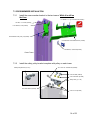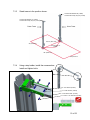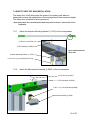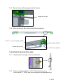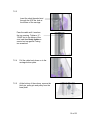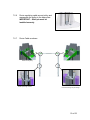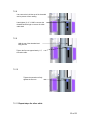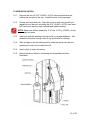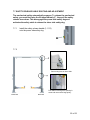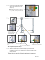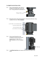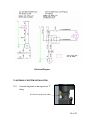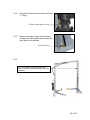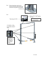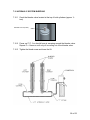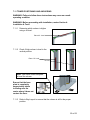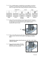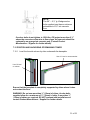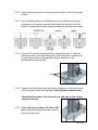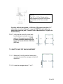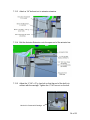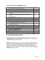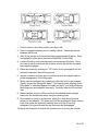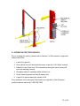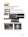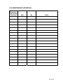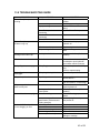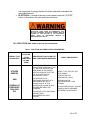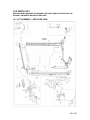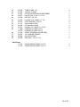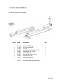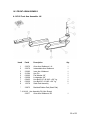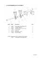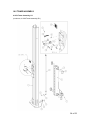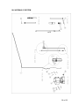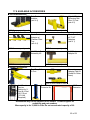
1
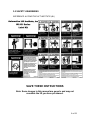
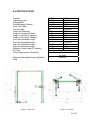
INSTALLATION
and OPERATION
MANUAL
2-POST
42010CA / 42010CA14
10,000 LB.
(ASYMMETRICAL)
READ THIS INSTRUCTION MANUAL THOROUGHLY
BEFORE INSTALLING, OPERATING, SERVICING OR
MAINTAINING THE LIFT.
SAVE THIS MANUAL.
309 EXCHANGE AVENUE,
CONWAY, ARKANSAS, 72032
TEL: 501-450-1500 FAX: 501-450-1585
JUL 2013
REV.-
6-2911
Table of Contents
1.0 OWNER / EMPLOYER OBLIGATIONS ......................................................... 4 2.0 IMPORTANT SAFETY INSTRUCTIONS ........................................................ 5 3.0 SAFETY AWARENESS ................................................................................. 8 4.0 SPECIFICATIONS .......................................................................................... 9 5.0 PACKING LIST............................................................................................. 10 6.0 INSTALLATION REQUIREMENTS AND TOOLS ........................................ 11 6.1 FOUNDATION .......................................................................................... 11 6.2 TOOLS ...................................................................................................... 11 7.0 INSTALLATION INSTRUCTIONS ................................................................ 12 7.1 UNPACKING PROCEDURE ..................................................................... 12 7.2 BAY LAYOUT ........................................................................................... 13 7.3 CROSSMEMBER INSTALLATION .......................................................... 14 7.4 SAFETY SHUT-OFF BAR INSTALLATION ............................................. 16 7.5 ROUTING OF EQUALIZATION CABLE ................................................... 17 7.6 ARM INSTALLATION ............................................................................... 21 7.7 SAFETY RELEASE CABLE ROUTING AND ADJUSTMENT ................. 22 7.8 POWER PACK INSTALLATION .............................................................. 24 7.9 HYDRAULIC SYSTEM INSTALLATION .................................................. 25 7.10 HYDRAULIC SYSTEM BLEEDING ........................................................ 28 7.11 TOWER POSITIONING AND ANCHORING ........................................... 29 7.12 POSITION AND ANCHORING OF REMAINING TOWER ...................... 31 7.13 SAFETY SHUT-OFF BAR ADJUSTMENT ............................................. 33 8.0 FINAL CHECK OF ASSEMBLED LIFT ........................................................ 35 9.0 OPERATING INSTRUCTIONS ..................................................................... 35 9.1 OPERATION TEST WITH VEHICLE ........................................................ 37 10.0 MAINTENANCE GUIDELINES................................................................... 38 11.0 WIRE ROPES ............................................................................................. 39 11.1 WIRE ROPE CONDITION GUIDE .......................................................... 39 11.2 WIRE ROPE REPLACEMENT CRITERIA: ............................................ 40 11.3 WIRE ROPE INSPECTION ..................................................................... 40 11.4 WIRE ROPE LUBRICATION .................................................................. 41 11.5 WIRE ROPE ADJUSTMENT .................................................................. 41 12.0 MAINTENANCE SCHEDULE ..................................................................... 42 2 of 62
13.0 TROUBLESHOOTING GUIDE ................................................................... 43 14.0 LOCK OUT AND TAG OUT INSTRUCTIONS............................................ 44 14.1 SHUT DOWN PROCEDURE: ................................................................. 44 14.2 ISOLATION AND VERIFICAITON PROCEDURES: .............................. 45 14.3 RETURNING TO SERVICE: ................................................................... 46 15.0 EMERGENCY OPERATION: ..................................................................... 47 IF THE MECHANICAL LOCKS ARE NOT ENGAGED: ................................. 47 IF THE MECHANICAL LOCKS ARE ENGAGED:.......................................... 47 16.0 PARTS LIST ............................................................................................... 48 16.1 LIFT ASSEMBLY - EXPLODED VIEW ................................................... 48 16.2 REAR ARM ASSEMBLIES ..................................................................... 51 16.3 FRONT ARM ASSEMBLY ...................................................................... 52 16.4 CROSSMEMBER PULLEY ASSEMBLY ................................................ 53 16.5 TOWER ASSEMBLY .............................................................................. 54 16.6 HYDRAULIC SYSTEM ........................................................................... 56 16.7 POWER PACK PARTS LIST: TYPE 1 ................................................... 58 16.8 POWER PACK PARTS LIST: TYPE 2 ................................................... 60 17.0 AVAILABLE ACCESSORIES .................................................................... 62 3 of 62
1.0 OWNER / EMPLOYER OBLIGATIONS
1. The Owner/Employer shall ensure that lift operators are qualified and that
they are trained in the safe use and operation of the lift using the
manufacturer’s operating instructions; ALI/SM 93-1, ALI Lifting it Right
safety manual; ALI/ST-90 ALI Safety Tips card; ANSI/ALI ALOIM-2008,
American National Standard for Automotive Lifts - Safety
Requirements for Operation, Inspection and Maintenance; ALI/WL
Series, ALI Uniform Warning Label Decals/Placards; and in the case of
frame engaging lifts, ALI/LP-GUIDE, Vehicle Lifting Points/Quick
Reference Guide for Frame Engaging Lifts.
2. The Owner/Employer shall establish procedures to periodically inspect the
lift in accordance with the lift manufacturer’s instructions or ANSI/ALI
ALOIM-2008, American National Standard for Automotive Lifts Safety Requirements for Operation, Inspection and Maintenance; and
the Employer shall ensure that the lift inspectors are qualified and that
they are adequately trained in the inspection of the lift.
3. The Owner/Employer shall establish procedures to periodically maintain
the lift in accordance with the lift manufacturer’s instructions or ANSI/ALI
ALOIM-2008, American National Standard for Automotive Lifts Safety Requirements for Operation, Inspection and Maintenance; and
the Employer shall ensure that the lift maintenance personnel are qualified
and that they are adequately trained in the maintenance of the lift.
4. The Owner/Employer shall maintain the periodic inspection and
maintenance records recommended by the lift manufacturer’s instructions
or ANSI/ALI ALOIM-2008, American National Standard for Automotive
Lifts - Safety Requirements for Operation, Inspection and
Maintenance.
5. The Owner/Employer shall display the lift manufacturer’s operating
instructions; ALI/SM 93-1, ALI Lifting it Right safety manual; ALI/ST-90
ALI Safety Tips card; ANSI/ALI ALOIM-2008, American National
Standard for Automotive Lifts - Safety Requirements for Operation,
Inspection and Maintenance; ALI/WL Series, ALI Uniform Warning
Label Decals/Placards; and in the case of frame engaging lifts, ALI/LPGUIDE, Vehicle Lifting Points/Quick Reference Guide for Frame
Engaging Lifts in a conspicuous location in the lift area convenient to the
operator.
6. The Owner/Operator shall provide necessary lockout/tagout means for
energy sources per ANSI Z244.1-1982 (R1993), Safety Requirements
for the Lockout/Tagout of Energy Sources, before beginning any lift
repairs and maintenance.
4 of 62
7. The Owner/Employer shall not modify the lift in any manner without the
prior written consent of the manufacturer.
2.0 IMPORTANT SAFETY INSTRUCTIONS
1. When using this lift, basic safety precautions should always be
followed, including the following:
2. Read all instructions in this manual and on the lift thoroughly before
installing, operating, servicing or maintaining the lift.
3. Care must be taken as burns can occur from touching hot parts.
4. Do not operate equipment with a damaged cord or if the equipment has
been dropped or damaged – until it has been examined by a qualified
service person.
5. Do not let a cord hang over the edge of the table, bench, or counter or
come in contact with hot manifolds or moving fan blades.
6. If an extension cord is necessary, a cord with a current rating equal to or
more than that of the equipment should be used. Cords rated for less
current than the equipment may overheat. Care should be taken to
arrange the cord so that it will not be tripped over or pulled.
7. Always unplug equipment from electrical outlet when not in use. Never
use the cord to pull the plug from the outlet. Grasp plug and pull to
disconnect.
8. Let equipment cool completely before putting away. Loop cord loosely
around equipment when storing.
9. To reduce the risk of fire, do not operate equipment in the vicinity of open
containers of flammable liquids (gasoline).
10. Adequate ventilation should be provided when working on operating
internal combustion engines.
11. Keep hair, loose clothing, fingers, and all parts of body away from moving
parts.
12. To reduce the risk of electric shock, do not use on wet surfaces or expose
to rain.
5 of 62
13. Use only as described in this manual. Use only manufacturer’s
recommended attachments.
14. ALWAYS WEAR SAFETY GLASSES. Everyday eyeglasses only have
impact resistant lenses, they are not safety glasses.
15. Inspect lift daily. Do not operate if it malfunctions or problems have been
encountered.
16. Never attempt to overload the lift. The manufacturer’s rated capacity is
shown on the identification label on the power side column. Do not
override the operating controls or the warranty will be void.
17. Before driving vehicle between the towers, position the arms to the drivethrough position to ensure unobstructed clearance. Do not hit or run over
arms as this could damage the lift and/or vehicle.
18. Only trained and authorized personnel should operate the lift. Do not allow
customers or bystanders to operate the lift or be in the lift area.
19. Position the lift support pads to contact the vehicle manufacturers
recommended lifting points. Raise the lift until the pads contact the
vehicle. Check pads for secure contact with the vehicle. Check all arm
restraints and insure they are properly engaged. Raise the lift to the
desired working height.
20. Some pickup trucks may require an optional truck adapter to clear running
boards or other accessories.
21. NOTE: Always use all 4 arms to raise and support vehicle.
22. Caution! Never work under the lift unless the mechanical safety locks are
engaged.
23. Note that the removal or installation of some vehicle parts may cause a
critical load shift in the center of gravity and may cause the vehicle to
become unstable. Refer to the vehicle manufacturer’s service manual for
recommended procedures.
24. Always keep the lift area free of obstruction and debris. Grease and oil
spills should always be cleaned up immediately.
25. Never raise vehicle with passengers inside.
26. Before lowering check area for any obstructions.
6 of 62
27. Before removing the vehicle from the lift area, position the arms to the
drive-thru position to prevent damage to the lift and /or vehicle.
28. Do not remove hydraulic fittings while under pressure.
For additional safety instructions regarding lifting, lift types, warning labels,
preparing to lift, vehicle spotting, vehicle lifting, maintaining load stability,
emergency procedures, vehicle lowering, lift limitations, lift maintenance,
good shop practices, installation, operator training and owner/employer
responsibilities, please refer to “Lifting It Right” (ALI/SM) and “Safety Tips”
(ALI/ST) and vehicle lift points for service garage lifting SAE J2184.
For additional instruction on general requirements for lift operation, please
refer to “Automotive Lift-Safety Requirements For Operation, Inspection and
Maintenance” (ANSI/ALI ALOIM).
Installation shall be performed in accordance with ANSO/ALI ALIS, Safety
Requirements for Installation and Service of Automotive Lifts.
ATTENTION! This lift is intended for indoor installation only. It is
prohibited to install this product outdoors. Operating environment
temperature range should be 41 – 104 °F (5 – 40 °C). Failure to
adhere will result in decertification, loss of warranty, and
possible damage to the equipment.
7 of 62
3.0 SAFETY AWARENESS
REFERENCE: AUTOMOTIVE LIFT INSTITUTE (ALI)
SAVE THESE INSTRUCTIONS
Note: Some images in this manual are generic and may not
resemble the lift you have purchased.
8 of 62
4.0 SPECIFICATIONS
Capacity:
Capacity per arm:
Overall Width:
Width Between Columns:
Drive-Thru Width:
Overall Height:
Under bar Clearance:
Height to Lowered Lift Pads
Height to Lift Pad (3” Adapter):
Height to Lift Pad (6” Adapter):
Front Arm Retracted Length:
Front Arm Extended Length:
Rear Arm Retracted Length:
Rear Arm Extended Length:
Maximum Lifting Height (6” Adapter):
Lift Time:
Power Requirements (Standard):
Maximum Operating Pressure @ Rated
Load:
Figure 1 - Front View
10 000 lbs.
2500 lbs
140 ¾”
106 ¾”
87½”
144”
140”
4 3/8”
7 5/8”
10 3/8”
23 3/4”
45”
35 1/8”
57 ½”
79 5/8”
4536 kg
1134 kg
3575 mm
2709 mm
2222 mm
3658 mm
3556 mm
112 mm
193 mm
264 mm
603 mm
1143 mm
891 mm
1461 mm
2022 mm
45 seconds
230 Volts AC, 1 Ph., 60 Hz
20 Amps
2680 psi
Figure 2 - Top View
9 of 62
5.0 PACKING LIST
The complete lift is contained in two (2) packages:
1. The main structural components are packed in a steel frame.
2. The remaining parts are packed in an accessory box.
3.1 Main Structural Components
1pc. - Power side tower and carriage assembly
1pc. - Slave side tower and carriage assembly
1pc. - Crossmember
1pc. - Actuator Bar w/ foam
3.2 Accessory Box
4pcs. - Locking Arm Assembly w/arm pins
2pcs. - Safety Covers w/Decals
1pc. - Hardware Package w/Packing List
1pc. - Actuator Extension
1pc. - Actuator Mounting Bracket
1pc. - Power Pack
4pc. - Arm Restraint
4pc. - Stack Pad Assembly
4pc. - Stack Pad Adapter (3”)
4pc. - Stack Pad Adapter (6”)
1pc. - Safety Release Cable
1pc. - Hydraulic Hose (Long)
1pc. - Hydraulic Hose (Short)
2pcs. - Equalizing Cable w/Hex Nuts
1pc. - ALI manual “Lifting It Right”
1pc. - Automotive Lift Safety Tips
1pc. - Automotive Lift, Operation, Inspection and Maintenance manual
1pc. - “ALI” Quick Reference Guide
1pc. - Owner’s manual
1pc. - Safety Shut-off Microswitch Assembly (Components)
10 of 62
6.0 INSTALLATION REQUIREMENTS AND TOOLS
6.1 FOUNDATION
IMPORTANT: It is the user’s responsibility to provide a satisfactory installation
area for the lift. Lifts should only be installed on level concrete floors with a
minimum thickness of six inches (6") or 152 mm. Concrete must have a minimum
strength of 4000 psi or 28 MPa and should be aged thirty (30) days prior to
installation. Please consult the architect, contractor or engineer if doubt exists as
to the strength and feasibility of the floor to enable proper lift installation and
operation.
A qualified person should be consulted to address seismic loads and other local
or state requirements.
It is the user’s responsibility to provide all wiring for electrical hook-up prior to
installation and to insure that the electrical installation conforms to local building
codes. Where required, it is the user’s responsibility to provide an electrical
isolation switch located in close proximity to the lift that will enable emergency
stop capability and isolate electrical power from the lift for any servicing
requirements.
6.2 TOOLS
Tools Required
a. 16ft. Measuring Tape
b. Chalk Line
c. Rotary Hammer Drill
d. 3/4” diameter Masonry Drill Bit
e. Hammer
f. SAE Wrenches and Ratchet Set
g. 2ft. Level
h. 4ft. Level
i. Crow Bar
j. 12ft. Step Ladder
k. Side Cutters
l. Screwdrivers
m. 4” x 4” Wooden Blocks (for unpacking)
n. Wherever LOCTITE symbol is shown, apply LOCTITE #242 on required
fasteners. If fasteners are removed reapply LOCTITE before re-installing.
11 of 62
7.0 INSTALLATION INSTRUCTIONS
When the lift arrives on site:
•
•
•
•
Read the owner’s manual and make sure the installation instructions are
fully understood.
Check for any freight damages.
Check the contents of the accessory and hardware boxes to make sure no
parts are missing.
Gather all the tools listed above.
7.1 UNPACKING PROCEDURE
1. Important! Place the main structural components on wooden blocks so
that the steel shipping frames can be removed.
2. Remove the plastic wrapping.
3. Remove the crossmember, and the actuator bar.
4. Unbolt the steel shipping frames.
5. Lay each tower on the floor with the carriage side up.
6. Check the installation area for obstructions. (Lights, Heating Ducts,
Ceiling, Floor Drains, etc.)
12 of 62
7.2 BAY LAYOUT
7.2.1 Prepare the bay by selecting the location of the lift relative to the walls.
7.2.2 Clear the installation area of all packaging materials to avoid trip hazards.
7.2.3 Measure midpoint of door.
7.2.4 Using measuring tape scribe two
arcs, equal distance from the
midpoint.
7.2.5 The centerline of the lift occurs
between the intersection of the arcs
and the midpoint of the door. Refer
to Figure 3.
Note: Leave any additional room for
any desired aisle or work area.
Recommended clearance
Figure 3. Chalk line
around lift is three feet (3 ft)
and above lift is four inches (4”). Ensure clearance conforms to local
building and fire codes.
7.2.6 Measure the specified distance
(156”) to draw a second chalk
line at 90° for locating the lift towers.
Refer to Figure 4.
7.2.7 The lift is centered between the
door and the walls of the area.
Bay Layout
13 of 62
7.3 CROSSMEMBER INSTALLATION
7.3.1
Install the cross member bracket to the two towers. While it is still on
the floor.
½”-16UNC x 1 ½” lg. hex head bolts (6-0291)
Hex Nut, ½”-13 UNC (6-0035)
Lock Washer, ½”ID (6-0059)
Crossmember Pulley Assy LS (2-2962)
Crossmember Channel Bracket LS (3-0995)
Flat Washer, ½”ID SAE (6-0248)
Power Tower
7.3.2
Install the safety pulley bracket complete with pulley on each tower.
Safety Pulley Bracket (2-1477)
3/8” x 5/8” LG. shoulder bolt (6-0069)
5/16” Hex Bolt (6-0423)
5/16” lockwasher (6-0296)
Safety Pulley (1-1116)
5/16” Flat Washer (6-0295)
5/16” hex nut (6-0294)
14 of 62
7.3.3
Stand towers in the position shown.
Crossmember Bracket RS (3-0996)
Crossmember Pulley Assy RS (2-2322)
Crossmember Bracket LS (3-0995)
Crossmember Pulley Assy LS (2-2321)
Power Tower
Slave Tower
136 1/2” (3467 mm)
96” (2438 mm)
Vehicle Center of
Gravity
156” (3962 mm)
Bay Entrance
7.3.4
Using a step ladder, install the crossmember.
Install and tighten bolts.
1/2” Lock Washer (6-0059)
½”-13 UNC Hex Nut (6-0035)
½” Flat Washer SAE (6-0248)
½”-13 UNC 1” LG. HEX BOLT (6-0045)
15 of 62
7.4 SAFETY SHUT-OFF BAR INSTALLATION
The safety shut off will disconnect the power to the power pack when an
obstruction touches the padded bar or the carriages reach their maximum height.
The safety shut off switch is factory pre-wired.
* Note: Bolt pattern for crossmember brackets may not be as shown – See section 5.3 for
installation.
7.4.1
Attach the Actuator Mounting Bracket (1-1378) to the crossmember
¼” NC hex nut (6-0032)
¼”ID lockwasher (6-0056)
Note: Install bracket on
Slave side.
Actuator Mounting Bracket (1-1378)
¼” NC x 3/4” lg. hex head bolt (6-0178)
7.4.2
Attach the Microswitch Assembly (2-2024) to the crossmember.
¼” NC hex nut (6-0032)
¼”ID lockwasher (6-0056)
¼” NC x 1” lg. hex head bolt (6-0008)
Microswitch Assembly (2-2024)
16 of 62
7.4.3 Slide the Actuator Bar through the Switch Bracket.
Actuator Bar (2-1240)
7.4.4 Attach the Actuator Bar to the Actuator Mounting Bracket.
¼” NC x 1 ½” lg. hex head bolt (6-0205)
¼”ID lockwasher (6-0056)
Actuator Bar (2-2140)
¼” NC hex nut (6-0032)
7.5 ROUTING OF EQUALIZATION CABLE
7.5.1
Manually lift the carriages to the first safety latch.
7.5.2
Remove equalizing cables (1-1473 *12ft) from the accessory
kit box, and 8 ½”- 13UNC nuts from a polybag in the hardware kit box.
17 of 62
7.5.3
Insert the short threaded stud
through the 9/16”dia. hole at
the bottom of the carriage.
Pass the cable until it reaches
the top opening. Tighten a ½”13UNC nut to the center of the
stud, and then firmly tighten a
second nut up against it using
two wrenches.
7.5.4
Pull the cable back down on to the
carriage bottom plate.
7.5.5
At the bottom of the column, remove the
hitch pin, pulley pin and pulley from the
base plate.
18 of 62
7.5.6
Route equalizing cable around pulley and
reassemble the pulley to the base plate.
IMPORTANT – Hitch pin must be
installed securely.
7.5.7
Route Cable as shown.
Route around pulley.
Route Up through column.
Insert stud through top of carriage.
19 of 62
7.5.8
Use a wrench to hold the top of the threaded
stud to prevent it from rotating.
Hand tighten (2) ½”-13 UNC nuts onto the
threaded stud enough to remove all visible
cable slack
7.5.9
Hold the top of the threaded stud
using wrench.
Tighten the first nut approximately 1 ½”
to tension cable.
7.5.10
Tighten the second nut firmly
against the first one.
7.5.11 Repeat steps for other cable.
20 of 62
7.6 ARM INSTALLATION
7.6.1
Remove the four (4) 5/16”-18UNC x 3/4”LG. hex head bolts that are
holding the arm pins to the arm. Install the arms on the carriages.
7.6.2
Grease and insert arm pins. Align the notch on each arm pin with the
tapped hole on the arm, and using the 5/16”-18UNC x 3/4”LG. hex head
bolt removed in previous step, reinstall and tighten securely.
NOTE: Make sure the hex head bolts, 5/16” dia. x 3/4” lg. (6-0801), is lock
tight into arms.
7.6.3
Insert arm restraint weldment through holes in carriage weldment. Arm
restraints must pass through holes in top and bottom of carriage.
7.6.4
With carriage on the first safety position, slide the spring onto the arm
restraint pin closer to the inside of the lift.
7.6.5
Insert roll pin to retain the spring.
7.6.6
Repeat the above steps for remaining Arm Assemblies and Arm
Restraints.
21 of 62
7.7 SAFETY RELEASE CABLE ROUTING AND ADJUSTMENT
The mechanical safety automatically engages. To release the mechanical
safety, you must first raise the lift approximately 2”, then pull the safety
release lever down. This disengages the power side safety dog and
activates the safety cable to release the slave side safety dog.
7.7.1
Install the safety release handle (1-1113)
onto the power side safety dog.
7.7.2
Start routing here on slave side.
Pull cable out through the opening in
tower and route under large pulley.
Power Side
Slave Side
22 of 62
7.7.3
Fix the collar of the safety release
cable to the shoulder bolt on the
safety dog.
NOTE: Make sure shoulder bolt, 3/8” dia. x
1 ½” lg. (6-0801), is lock tight to safety dog.
7.7.4
Guide the cable up
under the large pulley
on the power side.
Over the small pulley
towards the safety
dog.
Power Side
Slave Side
Wrap around the Thimble (6-2074)
Clamp using wire rope clips (6-2060)
3/8” x 1 1/2” lg. shoulder bolt (6-0801)
Do not tighten fully at this stage.
7.7.5
Adjust the cable length so that both safety dogs travel from full
engagement position to full release position when the safety release
handle is pulled.
Tighten both wire rope clips firmly when adjustment is completed.
23 of 62
7.8 POWER PACK INSTALLATION
7.8.1
Remove the red plastic cap located at
the rear of the power pack, and install
the "T" fitting located in the hardware kit.
T-Fitting (6-1506)
7.8.2
Bolt power pack to the mounting bracket on the power side tower using
hardware from the kit. Do not tighten.
(4) 5/16”-18UNC x 1”LG. hex head bolts (6-0293)
(4) 5/16” ID lock washers (6-0674)
(4) 5/16” ID flat washers (6-0295)
(4) 5/16”-18UNC hex nuts (6-0294)
7.8.3
Remove the filler cap from the
powerpack and fill the reservoir with
approximately 4.5 Gal. (18L) of
ISO32 hydraulic oil (10 wt. hydraulic
oil).
Filler Cap
7.8.4
A certified electrician must connect the 230Volt/1Ph power to the
motor.
24 of 62
Electrical Diagram
7.9 HYDRAULIC SYSTEM INSTALLATION
7.9.1
Connect long hose to the top port on “T”
fitting.
45° End of Long Hose (2-1486)
25 of 62
7.9.2
Connect short hose to the other end of the
“T” fitting.
45° End of Short Hose (2-1230)
7.9.3
Remove the plastic cap from the bottom
of the power side cylinder and connect the
short hose to the cylinder.
90° End of Hose
7.9.4
Loop the hydraulic hose up the power side
tower, across the overhead and down the slave
side tower.
26 of 62
7.9.5
Remove the plastic cap from the
bottom of the slave side cylinder and
connect the long hose to the cylinder.
90° End of Hose
7.9.6
#12 x 1/2” LG. Self Tapping
(6-1134)
Tube clamp (6-1547)
Place 3 tube clamps
on crossmember.
1/4”-20UNC x 3/8”lg.
round head screws (61353)
Use 6 tube
clamps to secure
the long and
short hydraulic
hoses to the
Towers.
27 of 62
7.10 HYDRAULIC SYSTEM BLEEDING
7.10.1 Crack the bleeder valve located at the top of both cylinders (approx. ¼
turn)
BLEEDER VALVE (6-3666)
7.10.2 Power up 2”-3”. You should hear air escaping around the bleeder valve.
Repeat 3 – 4 times or until only oil is coming out of the bleeder valve.
7.10.3 Tighten the bleed screw and lower the lift.
28 of 62
7.11 TOWER POSITIONING AND ANCHORING
WARNING! Failure to follow these instructions may cause an unsafe
operating condition.
WARNING! Before proceeding with installation, review Section 4:
Installation & Tools.
7.11.1 Determine which column is higher
using a 4ft level.
Place 4 ft. Level.
7.11.2 Check if high column is level in the
vertical position.
Place 2 ft. Level.
Note: Use shims under baseplate
to level the column.
Ensure that the base
plate is completely
supported by shims
including near the
center where it does not
contact the floor.
7.11.3 Refer to Bay Layout to ensure that the column is still in the proper
position.
29 of 62
7.11.4 Prior to installing anchors, assemble the nut and washer onto anchors.
A minimum of six threads must be visible below the surface of the nut.
Refer to the figure below while reading through the following instructions.
7.11.5 Using a 3/4” concrete drill bit and rotary hammer drill, drill ¾” holes for
the anchor bolts on the high side column. Drill through the concrete floor.
(In case longer anchors are required, supplied anchors can be
hammered through concrete).
Drill
7.11.6 Clean out the drilling dust from the holes and hammer in the anchor bolts
until they make contact with the baseplate. Hand tighten all anchor
bolts.
Check that the column is level front to rear and side to side. Adjust
shims as required.
7.11.7 Torque all anchor bolts to 150 ft-lbs.
(203 Nm), continually checking that the
column is level as you proceed.
30 of 62
NOTE:
The 3/4” × 5 ½” lg. Wedge anchor
bolts supplied must have a minimum
embedment of 3¼” into concrete
floor.
If anchor bolts do not tighten to 150 ft-lbs. OR project more than 2 ¼”
above the concrete surface due to floor slope, the concrete should be
replaced by an appropriate concrete pad. (Consult Product
Manufacturer / Supplier for further details).
7.12 POSITION AND ANCHORING OF REMAINING TOWER
7.12.1 Level the low side column by shim underneath the baseplate.
Use 4 ft. level on cross member.
Use 2 ft level
on column.
Ensure that the baseplate is completely supported by shims where it does
not contact the floor.
WARNING! Do not use more than ½” (13mm) of shims. Anchor bolts
supplied allow for a maximum of ½” (13mm) of shim. If more than ½”
(13mm) of shims are required, DO NOT proceed with installation and
contact Product Manufacturer / Supplier for further details.
31 of 62
7.12.2 Refer to Bay Layout above to ensure that the column is still in the proper
position.
7.12.3 Prior to installing anchors, assemble the nut and washer onto anchors.
A minimum of six threads must be visible below the surface of the nut.
Refer to the figure below while reading through the following instructions.
7.12.4 Using a 3/4” concrete drill bit and rotary hammer drill, drill ¾” holes for
the anchor bolts on the high side column. Drill through the concrete floor.
(In case longer anchors are required, supplied anchors can be
hammered through concrete).
Drill
7.12.5 Clean out the drilling dust from the holes and hammer in the anchor bolts
until they make contact with baseplate. Hand tighten all anchor bolts.
Check that the column is level front to rear and side to side. Adjust
shims as required.
7.12.6 Torque all anchor bolts to 150 ft-lbs. (203
Nm), continually checking that the column is
level as you proceed.
32 of 62
NOTE:
The 3/4” × 5 ½” lg. Wedge anchor
bolts supplied must have a minimum
embedment of 3¼” into concrete
floor.
If anchor bolts do not tighten to 150 ft-lbs. OR project more than 1 ¾”
above the concrete surface, the concrete MUST be replaced by an
appropriate concrete pad. (Consult Product Manufacturer / Supplier for
further details).
7.12.7 Verify that the entire lift is level both
horizontally and vertically to ensure
optimum lifting performance. NOTE:
Perform a monthly inspection and
torque all anchor bolts to 150 ft-lbs.
(203 Nm).
7.13 SAFETY SHUT-OFF BAR ADJUSTMENT
7.13.1 When the lift is fully installed, leveled and
operational, extend the carriages to their full
upper limit.
7.13.2 Lower the carriages about ¼” to ½”.
33 of 62
7.13.3 Attach a 1/4" bolt and nut to actuator extension.
7.13.4 Bolt the Actuator Extension onto the open end of the actuator bar.
7.13.5 Adjust the ¼” NC x 2” lg. hex bolt so that the end of the bolt is in
contact with the carriage. Tighten the ¼” NC hex nut on the bolt.
Hex bolt in Contact with Carriage.
34 of 62
8.0 FINAL CHECK OF ASSEMBLED LIFT
1.
2.
3.
4.
5.
Final dimension check after anchoring
Check for hydraulic leaks.
Ensure cables are properly routed and free from obstructions.
Check jam nuts on cables are tightened.
Check that LOCTITE has been applied to all hardware where
required.
6. Check adjustment of safety release cable to ensure both
sides
7. working properly.
8. Re-check level of towers.
9. Check torque of anchor bolts.
10. Check all fasteners, tighten if necessary.
11. Check shut off at top of stroke to ensure lift shuts off.
12. Check proper operation of arm restraints.
13. Operate lift to full stroke then lower to ground while checking
for proper functionality.
14. Check proper operation of arm restraints.
15. Ensure Customer Care Kit is complete and given to operator.
16. Operation Manual
17. ANSI / ALI Lift It Right Manual
18. ANSI / ALI Safety Tip Card
19. ANSI / ALI ALIS Safety Requirements for Installation
20. ANSI / ALI Quick Reference Guide
21. Train end user on operation of lift.
9.0 OPERATING INSTRUCTIONS
Read and understand all safety and operation labels on the lift. Refer to the
"Lifting it Right" manual and "Safety Tips" card supplied to you for additional
important instructions and information.
NOTE: Some vehicles may have the manufacturer's Service Garage Lift Point
locations identified by triangle shape marks on its undercarriage (reference SAE
J2184). Also, there may be a label located on the right front door lock face
showing specific vehicle lift points. If the specific vehicle lift points are not
identified, refer to the "Typical Lift Points" figure below or the ANSI/ALI Lift Point
Guide included with your lift.
35 of 62
Figure 48
1. Position arms to drive-thru position (see figure 49).
2. Refer to supplied literature prior to loading vehicle. Center the vehicle
between the lift post.
3. Only lift the vehicle on the manufacturers recommended lift points. Refer
to supplied lift points guide (reference ANSI/SAE J2184-1992).
4. Locate lift pads on auto manufacturer's recommended lift points. Once
you have correctly positioned the lift arms, ensure that all arm restraints
are properly engaged.
5. Raise the vehicle by pushing the "UP" button on the powerpack until the
vehicle's suspension has left the ground.
6. Inspect to make sure there are no interference with any objects and for
proper engagement of the lifting pads.
7. Shake vehicle moderately by pushing on either the front or rear bumper.
Visually inspect the lifting pads again. If the vehicle starts slipping on the
lifting pads, or otherwise appears unstable on the lift, you have positioned
the swing arms and adapters incorrectly. Carefully lower the lift and start
over.
8. When satisfied, continue lift the vehicle to the desired working height,
lower onto the mechanical safety using the lowering lever.
9. Once vehicle is ready to be removed, raise lift so that the mechanical
safety can be released. Pull down and hold the mechanical safety release
lever, then press the hydraulic lowering lever until the lift has fully
collapsed to the grounds and the arm restraints are disengaged.
10. Swing the lift arms to the drive-thru position prior to moving the vehicle.
36 of 62
9.1 OPERATION TEST WITH VEHICLE
Prior to starting this section, please refer to Section 2 of this manual for important
safety instructions.
1. Lower lift to ground.
2. Drive vehicle on to lift and locate the arms as per the “Lift it Right” manual.
3. Raise lift to and lower onto 3-4 lock positions during full rise to ensure all
locks are working correctly.
4. Re-adjust cables if necessary while vehicle is on.
5. Check lowering speed and smooth decent rate.
6. Lower lift to ground and drive vehicle off lift.
If any problems occur during the final checkout or operation of the lift please
contact customer service at 1-800-268-7959
37 of 62
10.0 MAINTENANCE GUIDELINES
SAFETY INSTRUCTIONS
Refer to Section 2 for more Safety Instructions.
Read operating and safety manuals before using any lift.
Do not operate a lift that has been damaged or is in disrepair.
Proper inspection and maintenance is necessary for safe operation.
PERIODIC MAINTENANCE
DAILY:
1. Check all hydraulic lines and fittings for pinch points , damage , cracks or leaks
2. Check all electrical wiring for pinch points , cracks or damage
3. Check all moving parts for uneven or excessive wear
4. Repair or replace all damaged, defective, worn or broken components immediately.
5. Check the telescopic arms for movement. Clean any grease or oil from the lifting
adapters.
6. Raise and lower the lift at the beginning of each shift, without a vehicle on, to verify the lift
is leveled and operating properly.
EVERY TWO MONTHS:
1. Clean and re-grease slide block channels inside of both columns
2. Grease arm pins
3. Lubricate safety dogs and check safety release cable adjustment
4. Check arm restraints and lubricate
5. Check anchor bolts and re-torque if required
EVERY FOUR MONTHS:
1. Dismantle and clean inner arms
2. Lubricate cable pulleys
3. Check equalizing cable adjustment
EVERY YEAR:
1. Inspect lift as per Automotive Lift Operation, Inspection and Maintenance (ALOIM)
EVERY TWO YEARS:
1. Change hydraulic fluid
LUBRICATION:
Where grease is required > multi-purpose lithium grease
Where lubricating oil is required > multi-purpose SAE 30 lubricating oil
Where hydraulic oil is required > ISO 32 10W - non detergent hydraulic oil
NOTE:
If the lift locks, while in the fully raised position this will indicate that the
hydraulic system has not been inspected or maintained as recommended. This
is a safety back-up system. If you are unclear call your local
representative immediately.
38 of 62
11.0 WIRE ROPES
• Wire ropes are critical to safe and reliable performance of your lift.
• Cables are expendable items and should be replaced as a set.
11.1 WIRE ROPE CONDITION GUIDE
Typical good
cable
Cable with
necking
Broken wires
Excessive wear of wires
Rust on sheave stack and ropes
Corrugated sheave groove
(Pictures above are of a 4-Post Lift, conditions still apply to 2-Post Lifts)
39 of 62
11.2 WIRE ROPE REPLACEMENT CRITERIA:
If any cable is found to be in need of replacement, the entire
cable set, pulleys and safety rollers must be replaced
immediately.
See 10.1, cable conditions guide.
In the following table, "lay" means the distance
measured along a line parallel to the axis of the
rope in which the strand makes one complete turn
about the axis of the rope, or the wires make a
complete turn about the axis of the strand.
The wire rope must be removed from service if one or more of the following criteria
are met:
1. More than six randomly distributed broken wires in one rope lay or 6×d length.
2. More than three broken wires in one strand in one rope lay or 6×d length.
3. Three or more broken wires at rope terminations.
4. One outer wire broken at the point of contact with the core of the rope which has
worked its way out of the rope structure and protrudes or loops out from the rope
structure
5. Heavy rusting, corrosion, or pitting. A light surface corrosion on outer wires is normal.
6. Wear or scraping of one-third of the original diameter of outside individual wires
7. Excessive stretch. It is normal for new cable to require adjustment during “break-in”,
after which small periodic adjustments may be required. However, if a cable that has
been in service for 6 months should suddenly require frequent adjustments or has
used all the cable adjustment available, all cables must be replaced immediately.
8. Deformed strands, kinking, crushing, bird-caging, or any other damage or distortion
of wire rope structure
9. Variations in diameter (necking) or any change from normal appearance
10. Reductions from nominal diameter of more than 1/32" (for cables 3/8" to 1/2" dia.
inclusive)
11. End attachments cracked, deformed or worn
11.3 WIRE ROPE INSPECTION
Inspect wire rope cables for wear or damage. Wipe cables with a rag to detect
hard to see small broken or frayed cable strands. See chapter 9.2, Fig.75 and
ANSI/ALI ALOIM standard.
40 of 62
11.4 WIRE ROPE LUBRICATION
Lubricate wire ropes with lift in both lowered and raised position, by spraying
them with wire rope lubricant (i.e. 2001 MONOLEC®) and wiping the cable down.
11.5 WIRE ROPE ADJUSTMENT
Adjust cables if lifting is uneven or lift is not level (See chapter 7.15.3). Never
make adjustments with weight on lift. If running out of adjustment threads, cables
need to be replaced. Do not add washers or other spacers to re-use previously
used adjustment threads.
Wire rope tension adjustment should be performed when installing the lift and
every three months.
41 of 62
12.0 MAINTENANCE SCHEDULE
Maintenance
and Training
Performed
Date
By
Notes
42 of 62
13.0 TROUBLESHOOTING GUIDE
PROBLEM
Power Pack (Motor) not
running.
REASON
Bad Fuse or Circuit breaker.
Incorrect voltage to motor.
Improper wiring.
Power Pack (Motor) runs but
lift does not go up.
Power Pack up switch not
functioning.
Overhead Mircoswitch not
functioning.
Power Pack motor burned out.
Low oil level.
Oil valve remains open.
Pump sucking air.
SOLUTION
Replace bad fuse or reset circuit
breaker.
Provide proper voltage to motor.
Have certified electrician check
wiring.
Replace Power Pack up switch.
Replace overhead Microswitch.
Replace motor.
Fill reservoir with proper
hydraulic oil.
Repair or replace oil valve.
Tighten all fittings and suction
lines.
Bleed hydraulic lines (Call
installer).
Lift goes up slowly or oil
coming out from filler cap.
Air in hydraulic fluid lines
Lift doesn’t come down.
Dirt in directional valve
Call installer to clean valve. (Do
not attempt to open hydraulic
lines unless vehicle is secure)
Safety Dog does not engage.
Safety Dog jammed.
Safety Dog does not
disengage.
Lift goes up unlevel.
Safety dog is being limited
Oil or replace pin to free Safety
Dog.
Check or replace spring.
Check for any obstructions.
Equalizing cables are loose.
Floor unlevel.
Lift goes up with chatter or
does not fully rise.
Anchor bolts do not stay tight.
Low oil level.
Air in hydraulic fluid
lines/cylinder.
Holes are too large.
Incorrect concrete floor
specification (Thickness and
holding strength).
Noticeable Deflection of Arm
or arm dragging on floor.
Lift out of plumb.
Unlevel floor.
Worn arm or carriage holes.
Worn carriage slide blocks.
Bent arm (Overloaded).
Adjust equalizing cables to
correct tension.
Shim lift to make towers level.
(Do not exceed ½” of shimming).
Fill reservoir to correct level with
proper hydraulic oil.
Bleed hydraulic lines. (Call
installer).
Relocate lift using proper size
drill bit.
Break existing floor and pour
new pad for lift.
Plumb columns.
Replace floor of shim columns.
Replace parts.
Replace side blocks.
Replace arm. Also check
damage to carriage.
43 of 62
14.0 LOCK OUT AND TAG OUT INSTRUCTIONS
IMPORTANT: This machine does not have integral devices that will isolate
the electrical, pneumatic, stored and hydrualic energy source. Appropriate
isolation or blocking devices must be used that have the provisions to be
switched in the off position and locked in that position.
ALL MAINTANANCE AND SERVICE MUST BE PERFORMED BY A
QUALIFIED PERSON.
ALL MAINTANANCE AND SERVICE MUST BE PERFORMED WITH THE LIFT
UNLOADED.
IT IS THE SHOP OWNERS RESPONSIBILITY TO ENSURE ENERGY
ISOLATING DEVICES ARE:
•
•
•
•
•
•
Accessible
Conveniently located to facilitate the application of lockout devices
during service and maintenance
Located outside any hazardous area.
At a convenient manipulating height (i.e. not overhead, on ladders or
under machinery)
Adequately labeled or marked. Identification shall include machine
ID, energy type and magnitude.
Capable of being locked or otherwise secured in an effective
isolating position.
Effective hazardous energy control procedures will protect employees during
machine and equipment servicing and maintenance where the unexpected
energization, start up or release of stored energy could occur and cause injury,
as well as while working on or near exposed de-energized electrical conductors
and parts of electrical equipment. Hazards being guard against include being
caught in, being crushed by, being struck by, being thrown from, or contacting
live electrical circuits/parts.
In preparation for lockout, an initial survey must be made to locate and identify all
energy isolating devices to be certain which switch, valve, or other energy
isolating devices apply to the machine / equipment to be locked out. More than
one energy source (electrical, hydraulic, pneumatic, or others) may be involved.
14.1 SHUT DOWN PROCEDURE:
•
Notify all affected employees that a lockout or tagout system is going to be
utilized and the reason for. The authorized employee shall know the type
44 of 62
•
and magnitude of energy that the lift utilizes and shall understand the
associated hazards.
ELECTRICAL: Located at the user control panel, press the “E-STOP”
button to disconnect the raise and lower functions.
ELECTRICAL ENERGY IS STILL PRESENT AT THE LIFTS
ELECTRICAL PANEL WHEN THE EMERGENCY STOP
BUTTON IS PRESSED. ELECTRICAL ENERGY MUST BE
TURNED OFF AND ISOLATED AT THE DISCONNECT
PANEL
PRIOR
TO
PERFORMING
SERVICE
OR
MAINTANANCE ON THE LIFT.
14.2 ISOLATION AND VERIFICAITON PROCEDURES:
Table 1: ISOLATION AND VERIFICATION PROCEDURES:
LOCKOUT
LOCATION
ENERGY TYPE
AND SOURCE
STORED
ENERGY
AND
HYDRAULIC
PRESSURE
3000-5000
PSI
(TO BE
COMPLETED
BY END
USER)
PROCEDURE FOR LOCING OUT
AND OR RELEASING ENERGIES
LOWER THE LIFT TO ITS
LOWEST REST POSTION. IF THE
LIFT MUST BE SERVICED OR
MAINTAINED IN THE RAISED
POSITION, ENSURE THAT THE
LIFT IS PLACED ON THE
MECHANICAL LOCKS.
FOR SCISSOR LIFTS,
ADDITIONAL SUPPORT WITH
SUPPLEMENTARY JACK
STANDS, BLOCK AT THE
SLIDERS AND A COME ALONG
SECURED BETWEEN THE
SCISSORS.
FOR 4-POST LIFTS, ADDITIONAL
SUPPORT WITH
SUPPLEMENTARY JACK
STANDS.
VERIFY PROCEDURES
VERIFY THAT THE LIFT IS (IF
APPLICABLE):
CONTACTING THE
MECHANICAL LOCKS,
RESTING ON THE
SUPPLEMENTARY JACK
STANDS,
BLOCKS ARE SECURLY PLACED
COME ALONG IS SECURED
BETWEEN THE SCISSORS.
45 of 62
AT THE LIFT, PRESS THE
EMERGENCY STOP BUTTON
COMPLETELY TO DE-ENERGIZE
THE CONTROL BUTTONS (IF
APPLICABLE).
ELECTRICAL
240VOLTS
AT THE DISCONNECT PLANEL,
PLACE THE DISCONNECT
HANDLE IN OFF POSITION.
ATTACH A MULTIPLE LOCUOUT
DEVICE. LOCK AND TAG.
ATEMPT TO RESTART THE
SYSTEM, THE SYSTEM MUST
NOT START. VISUALLY VERIFY
OPEN DISCONNECTS AND
LOCKING DEVICE INSTALLED.
DANGER: LINE SIDE OF
DISCONNECT REMAINS
ENERGIZED
PNEUMATIC
UPTO
160PSI
SLOWLY CLOSE LOCKOUT
VALVE TO RELEASE AIR
PRESSURE GRADUALLY.
ATTACH MULTIPLE LOCKOUT
DEVICE, LOCK AND TAG.
DANGER: LINE SIDE OF
DISCONNECT REMAINS
PRESSURIZED
VERIFY THE VALVE IS CLOSED
AND LOCKOUT DEVICE IS
PROPERLY ATTACHED.
OPERATE THE PNEUMATIC
SYSTEM TO ENSURE THE
SYSTEM IS DE-ENERGIZED. IT
MAY BE NECESSARY TO BLEED
THE SYSTEM OF REMAINING
COMPRESSED AIR, THIS CAN
BE PERFORMED AT THE BASE
OF THE WATER SEPARATOR
BOWL.
14.3 RETURNING TO SERVICE:
•
Check the lift and the immediate area around the lift to ensure that
nonessential items,, tools and parts are removed and that the lift
components are operationally intact.
•
Check the work area to ensure that all employees have been safely
positioned or removed from the work area.
•
Notify all employees that the lockout/tagout is going to be removed and
the lift is going to restarted.
•
Remove the lockout/tagouts in the reverse order as the installation.
•
Verify the proper operation of the equipment.
•
Notify affected employees that the maintenance/service is completed and
the machine is ready for operation.
46 of 62
15.0 EMERGENCY OPERATION:
If the lift becomes inoperative in the raised position, it is best to wait until the
electrical power is restored before lowering the vehicle. However, if it’s critical to
safety that the lift be lowered, the following steps should be taken.
WARNING: DO NOT LOOSEN OR REMOVE HYDRAULIC
CONNECTIONS OR FITTINGS UNDER PRESSURE. SERIOUS
INJURY OR DEATH COULD OCCUR.
NOTE: Safely performing this process requires 3 people. All personnel
should stay clear of the path of the lift. All tools and other non-secured
items should be removed from the surface of the ruways.
1) Survey the area surrounding the lift; remove any items and personnel from
area before proceeding with this procedure.
2) Perform the appropriate lockout/tag out procedure on the electrical
energy.
3) Use a second person standing at a safe distance away from the lift to
keep watch on the area, lift, vehicle and other personnel throughout the
process. This person should signal the person performing the procedure
to stop if necessary.
4) Use a caution tape or similar to barrier the area around the lift to avoid
personnel from accidently entering the area while this process is being
performed.
5) Do not proceed with this procedure if you are unfamiliar with the lift or its
function.
IF THE MECHANICAL LOCKS ARE NOT ENGAGED:
1) Pull safety release lever simultaneously pressing the descent lever on the
powerpack.
2) Keep a close eye on the movement of the lift and the position of the
vehicle; release descent lever if any abnormal movement is detected.
3) Continue until the lift is fully lowered.
4) Once power is restored follow the lockout/tag out procedure to return the
lift back into service.
IF THE MECHANICAL LOCKS ARE ENGAGED:
Various methods can be used to raise the lift in order to get sufficient clearance
to disengage the mechanical locks. The safest method would employ temporary
electrical power to the lift using a portable power generator. Any electrical
connections should be done by a licensed electrician; lockout/tag out procedures
should also be employed at this time.
This process should only be performed by a trained professional. Contact
customer service or a local service professional for further assistance.
47 of 62
16.0 PARTS LIST
REPLACE WORN, DAMAGED OR BROKEN PARTS WITH PARTS APPROVED BY THE
ORIGINAL EQUIPMENT MANUFACTURER ONLY
16.1 LIFT ASSEMBLY - EXPLODED VIEW
48 of 62
Item #
1
2
3
4
5
6
7
8
9
10
11
12
13
14
15
16
17
18
19
20
21
22
23
24
25
26
27
28
29
30
31
32
33
35
37
38
39
40
41
42
43
44
Part #
4-1018
4-1020
3-0995
2-2323
3-0996
4-1019
4-1021
2-2962
2-2964
4-1381-6
4-1413-6
4-1414-6
6-2055
1-1378
6-0178
6-0056
6-0032
2-2024
6-0205
6-1379
2-1477
6-0069
1-1116
6-0296
6-0294
6-0423
6-0248
6-0045
6-0059
6-0035
3-0439
1-1113
6-1135
6-1134
2-2942
6-0295
1-4033
9-0114
2-1240
1-2012
6-0060
6-1353
2-1580
1-3280
Description
TOWER ASSEMBLY POWER SIDE 12FT
TOWER ASSEMBLY POWER SIDE 14FT
L.S. CROSSMEMBER CHANNEL BRACKET
CROSSMEMBER CHANNEL
R.S. CROSSMEMBER CHANNEL BRACKET
TOWER ASSEMBLT SLAVE SIDE 10K 12FT
TOWER ASSEMBLT SLAVE SIDE 10K 14FT
LS PULLEY ASSEMBLY
RS PULLEY ASSEMBLY
LONG ARM ASSEMBLY
ASYMMETRIC 3-STAGE ARM ASSEMBLY LH
ASYMMETRIC 3-STAGE ARM ASSEMBLY RH
Power Pack, 208-230 V, 1 PH
ACTUATOR MOUNTING BRACKET
Hex Bolt, ¼” x ¾” LG.
Lock Washer, ¼" I.D.
Hex Nut, 1/4"-20UNC
Microswitch Assembly
Hex HD. Bolt ¼” NC x 1 ½” LG.
Wedge Anchor 3/4" x 5 ½" LG. (c/w Washer & Nut)
PULLEY BRACKET
Shoulder Bolt, 3/8” DIA. X 5/8” LG.
SAFETY CABLE PULLEY
5/16" Lock Washer
HEX NUT, 5/16-18 UNC
Hex Bolt, 5/16” 18UNC x ¾” LG.
Flat Washer, ½” ID SAE
Hex HD Bolt, 1/2"-13UNC x 1" LG
Lock Washer, 1/2"
NUT, 1/2-13 UNC, HEX
SAFETY COVER
SAFETY RELEASE HANDLE
Plastic Knob
SELF TAPPING SCREW, #12 X 1/2" LG
ARM RESTRAINT WELDMENT
FLAT WASHER, 5/16" I.D.
HANDLE SPRING
Roll Pin, 4.5 mm x 30mm
Actuator Bar with Foam
ADAPTER HOLDER
Flat Washer, ¼" I.D.
Round HD. MACH. Screw 1/4"-20 x 3/8" LG.
6” HEIGHT ADAPTER
3” HEIGHT ADAPTER
Qty.
1
1
1
1
1
1
1
2
1
1
1
1
1
7
7
1
1
10
2
2
2
6
10
4
16
8
16
16
2
1
1
4
4
4
4
4
1
2
4
4
4
4
49 of 62
45
46
47
48
49
50
51
52
53
54
55
56
57
58
59
6-0536
2-1904
2-1907
6-0027
6-0034
6-0293
6-0674
6-1111
6-3039
6-0291
1 -2040
1-2673
2-1230
6-0626
6-0904
6-0008
* Not Shown
1-3781
1-3475
TUBE CLAMP, 1/2"
10K ASY. 2-POST
ACTUATOR EXTENSION WELDMENT
Hex HD. Bolt ¼” NC x 1 ¼” LG.
HEX NUT, 3/8" NC
Hex Bolt, 5/16”-18UNC x 1” LG.
LOCK WASHER, 5/16 I.D.
Serial Number Plate
Lift Operations Decal
Hex Bolt,1/2"-13UNC X 1 1/2 LG.
HYDRAULIC HOSE (12FT)
HYDRAULIC HOSE (14 FT)
SHORT HYDRAULIC HOSE ASS'Y
1/4" WASHER FENDER
9/16 ID EYE BOLT
HEX BOLT, 1/4" X 1" LG.
6
1
1
2
2
4
4
1
1
8
1
1
1
1
1
2
EQUALIZATION CABLE (12 FT)
EQUALIZATION CABLE (14 FT)
2
2
50 of 62
16.2 REAR ARM ASSEMBLIES
4-1381-6 Long Arm Assembly
Item#
Part#
Description
1
2
3
4
5
6
7
8
9
3-1136
3-1128
2-1594
6-0423
6-0062
6-0058
6-0030
6-3369
1-3278
Outer Arm Weldment
Inner Arm Weldment
Arm Pin
Hex Bolt 5/16"-18 UNC x 3/4" Lg.
Flat Washer 3/8" ID SAE
Lockwasher 3/8"
Hex Bolt 3/8" UNC x 3/4" Lg.
Nylon Jam Nut 3/8"
Stack Pad Assembly
*
3-0872
Moulded Rubber Pad (Stack Pad)
Qty.
1
1
1
1
1
1
1
1
1
51 of 62
16.3 FRONT ARM ASSEMBLY
4-1413-6 Front Arm Assembly, LH
Item#
Part#
Description
1
2
3
4
5
6
7
8
9
2-2976
2-2679
2-2682
2-1594
6-0062
6-0058
6-0423
6-0030
1-3278
Outer Arm Weldment, L.H.
Intermediate Arm Weldment
Inner Arm Weldment
Arm Pin
Flat Washer 3/8”
Lockwasher 3/8”
Hex Bolt 5/16"-18 UNC x 3/4" Lg.
Hex Bolt 3/8”-16 UNC x 3/4” Lg.
Stack Pad Assembly
*
3-0872
Moulded Rubber Pad (Stack Pad)
** 4-1414-6 Arm Assembly RH (Not Shown)
2-2977
Outer Arm Weldment, RH
Qty.
1
1
1
1
1
1
1
2
1
1
52 of 62
16.4 CROSSMEMBER PULLEY ASSEMBLY
Item#
1
2
3
4
5
6
7
Part#
Description
2-2963
1-3178
6-0978
1-3494
1-3172
6-0738
1-1898
Crossmember Pulley Bracket LH
Common Pulley Pin
Cotter Pin 1/8" Dia. X 1-1/2" Lg.
Cable Retainer
Pulley Pipe
Flat Washer, 3/4" ID
Pulley Assembly
2-2964 Crossmember Pulley Assembly RH (Not Shown)
2-2965
Crossmember Pulley Bracket RH
Qty.
1
1
1
2
1
2
2
1
53 of 62
16.5 TOWER ASSEMBLY
4-1378 Tower Assembly, LH
(not shown; 4-1380 Tower Assembly, RH)
54 of 62
Item#
1
2
3
4
5
6
7
8
9
10
11
12
13
14
15
16
17
18
19
20
21
Part #
4-1012
3-0621
4-1379
6-1510
6-2095
2-0772
6-0000
1-1898
1-1887
6-1841
2-1901
6-3965
1-1115
6-0206
1-0415
1-1116
1-2657
6-1766
1-2337
6-2445
6-1134
Description
Tower Weldment (Power)
Hydraulic Cylinder Assembly (Patriot)
Formed Carriage Weldment
Flow Control
Male Nipple, ¼" NPT
Slider Block
Grease Nipple
Pulley Assembly
Headed Pin
Hitch Pin, 1/8" DIA.
Safety Dog
Machine Screw, #8 x 1" Lg
Safety Spring
Shoulder Bolt, 3/8" DIA. x 1" LG.
Safety Cable Pulley
Safety Cable Pulley
Shim, Slider Block
Capacity Decal
Safety Lock Pin
Snap Ring ¾" EXT
Self-Tapping Screw, #12 x 1/2" Lg
Qty.
1
1
1
1
1
4
2
1
1
1
1
1
1
2
1
1
6
1
1
2
1
55 of 62
16.6 HYDRAULIC SYSTEM
56 of 62
Item
Part #
Description
1
6-2055
6-2665
6-3039
6-0294
6-0674
6-2095
6-3666
6-4083
6-1510
6-3162
6-3914
6-0295
6-0293
6-1506
1-2040
1-2673
2-1230
3-062101
Power Pack, 208-230V, 1 PH
Power Pack, 208-230V, 3 PH
“Lift Operation” Decal
Hex Nut, 5/16”-18 UNC
Lock Washer, 5/16” I.D.
Male Nipple, ¼” NPT
Bleeder Valve (Holmac)
Bleeder Valve (HWF Eagle)
Flow Control
Gland & Piston Seal Kit (Holmac Cylinder)
Gland & Piston Seal Kit (HWF Eagle Cylinder)
Flat Washer, 5/16” I.D.
Hex Bolt, 5/16”-18 UNC x 1” LG.
Branch Tee
Hydraulic Hose (Long-12’)
Hydraulic Hose (Long-14’)
Hydraulic Hose (Short)
Cylinder Assembly (Not INCL. Flow Control)
2
3
4
7
8
9
11
12
13
14
15
16
*
*
*
*
*
*
*
*
6-1575
2-1130
1-1369
6-0008
6-0056
6-0032
6-0094
8-0287
3PH Power Pack Includes the Following (Not Shown)
Contactor Box
Contactor Bracket
Cover Plate
Hex Bolt, ¼” –NC x 1” LG
Lock Washer, ¼”
Hex Nut, ¼” – NC
Strain Relief
Cable, 14/4
Qty
1
1
4
4
2
2
2
2
2
2
4
4
1
1
1
1
*
1
1
1
2
4
2
2
2 ft.
57 of 62
16.7 POWER PACK PARTS LIST: TYPE 1
58 of 62
46.832.17.0004 230 V / 1 PH / 60 HZ (6-2055 Oil-Systems)
Item
1
2
3
4
5
6
7
8
9
10
11*
Part #
6-3442
6-3443
6-3444
6-3445
6-3446
6-3447
6-3448
6-3452
6-3449
6-3450
6-3451
Description
PUMP 6.7G, 17 GEAR
SUCTION PIPE 3/8”
SUCTION FILTER 3/8” FEMALE 15 L/MIN
RETURN PIPE
PLASTIC TANK 12L
MOTOR SHAFT COUPLING PUMP
MANUAL VALVE
START UP VALVE
TANK BRACKET WITH SCREWS
MOTOR BRACKETS
PUSH BUTTON WITH MICROSWITCH
Qty
1
1
1
1
1
1
1
1
1
1
*NOT SHOWN IN DIAGRAM
59 of 62
16.8 POWER PACK PARTS LIST: TYPE 2
60 of 62
#6-2055 (AB-1381) 208-230V/1PH/60Hz
#6-2665 (AD-1044) 208-230V/3PH/60Hz
Item
1
2
4
6
7
9
10
11
12
13
14
15
16
17
18
19
20
21
22
24
25
27
28
29
30
31
32
33
34
35
37
38
39
40
41
42
Part #
6-1087
6-2136
6-1376
6-2139
6-1079
6-2149
6-2151
6-2152
6-2153
6-2154
6-2155
6-1958
6-1319
6-0880
6-2156
6-1090
6-0774
6-2157
6-2158
6-2159
6-2161
6-2162
6-2164
6-2165
6-2166
6-1392
6-2167
6-2168
6-0776
6-2169
6-2170
6-1091
6-0786
6-1089
6-1399
6-1846
6-0875
Description
VALVE CARTRIDGE CHECK
LABEL INSTALLATION AUTOHOIST
BREATHER CAP & BLADDER
MOTOR AC 208-230V, 2HP/1PH/60Hz, BLK
MOTOR AC 208-230V, 2HP/3PH/60Hz, BLK
LABEL WARNING AUTOHOIST
SPRING 0.480" X 0.063" X 0.42" COMP
RETURN HOSE 3/8" ID X 21.5"
COMPRESSION TUBE NUT
COMPRESSION TUBE SLEEVE
ENDHEAD UNIVERSAL AUTOHOIST
PUMP ASSY 2.5 CC/REV, SHORT SLINE
RELIEF ASSEMBLY AC 1PH FENNER
VALVE CARTRIDGE RELEASE MANUAL
WIRING ASSEMBLY AC 1PH FENNER
BOLT 5/16"-24 X 3.00" TORX G8
COUPLING SAE 9T-20/40 1.260"
PLUMBING PLUG 9/16" SAE
SEAL SHAFT 0.500" X 1.00" X 0.25"
WASHER 0.338" X 0.625" X 0.060" STEEL
PLUMBING PLUG 3/8" NPT
PLUMBING MAGNET
SCREW TAPTITE M6 X 1.0 12MM TORX
COVER ASSY SUCTION
PLUMBING CLAMP HOSE ADJ. INLET
BOLT 5/16"-18 X 1.00" SHCS
NUT 3/4"-16 X 1" HEX X 0.25" STEEL
WASHER 3/4" INT. TOOTH LOCK
BRACKET - HANDLE ASSY REL BLACK
BOLT M6 X 1.0 35MM SOC HD
WASHER 1/4" LOCK HI-COLLAR
BOLT #12-24 X 0.50" HEX HD WASHER
PLUMBING ASSY INLET 17.24 (3)
RELIEF VALVE CAP ASSEMBLY
TANK PLASTIC 6.7 OS 22.50" BLK
CABLE TIE 8" LONG WHITE
O-RING 2-348 BUNA
Qty
1
1
1
1
1
1
1
1
1
1
1
1
1
1
1
2
1
1
1
1
1
1
2
1
1
1
1
1
1
4
4
4
1
1
1
1
1
61 of 62
17.0 AVAILABLE ACCESSORIES
Flip Pad Accessories
Poly Pad
Adapter
(set of 4)
High Lift Truck
Extension MidRise / 2-Post
(set of 2)
3000 lb max capacity each
Stack Pad Accessories
2500 lb max capacity each
Stack Pad
Adapter w/
Checker Plate
Top
(set of 4)
3000 lb max capacity each
Stack Pad Ass’y
w/ 3” &6”
Adapters
(set of 1)
3000 lb max capacity each
1 ½” Stack Pad
Assembly Kit
3000 lb max capacity each
Common Accessories
4 ½” Stack
Adapter Kit
3000 lb max capacity each
Tool Tray Kit for
2-Post
Air / Electric
Service
Station for 2Post & 4-Post
(90-110 psi
110 Volts
Required)
3000 lb max capacity each
Foam Door
Protector Kit
Secondary
Adapter Pad Kit
(Used On Outer
Arms)
24” Tower
Extension
Accessories may not be available for all models. Contact supplier for
availability and part numbers.
Max capacity is for 12,000 Lb Lifts. Do not exceed rated capacity of lift.
62 of 62