1
4-10
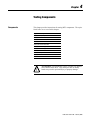
Testing Components
Testing the Isolation Board
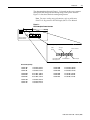
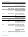
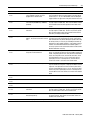
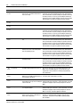
The isolation board receives feedback from the AC line, DC bus, current
transducers, main contactor (M1), and reset button. This feedback is passed
to the main control board for processing.
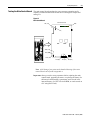
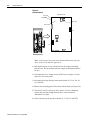
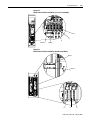
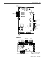
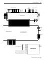
Figure 4.6
Isolation Board
TB3
Isolation Board
Burden
Resistors
TB6-6
TB6-9
SW1
TB2
TB1
Note: TB2 is used only in
Series B units.
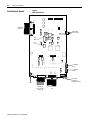
Note: A detailed illustration of the isolation board can be found in
Appendix A.
1. Push the disconnect lever to off and wait for all voltage to discharge
from the unit. Do not continue until all voltage has dissipated from the
DC bus.
2. Verify that there is no voltage across the DC bus (see Figure 4.12 and
Figure 4.13 for check points).
3. Verify that there is no voltage across the terminals and subcomponents of
the isolation board.
Publication 2364F-5.05 - February 2005