1
Reference Information
A-7
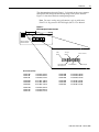
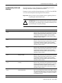
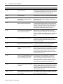
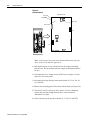
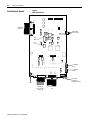
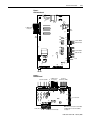
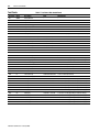
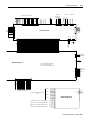
Table G: Test Points–Gate Driver Board
Test Points
Name
Description
Scale
Typical Range
TP1
+BUS
Positive Bus Input
1:1
½ rated DC bus voltage
TP2
-BUS
Negative Bus Input
1:1
½ rated DC bus voltage
TP3
+24V
+24V Power Supply
1:1
23.7 to 24.3V DC
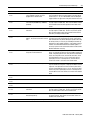
TP4
+5V
+5V Reference
1:1
4.8 to 5.4V DC
TP5
+15V
+15V Reference
1:1
14.4 to 15.4V DC
TP6
-15V
-15V Reference
1:1
-14.4 to -15.4V DC
TP7
DGND
Digital Ground
-
-
TP8
ISO12
Tachometer/Encoder
Not Used
-
TP9
ISO12RTN
Tachometer/Encoder
Not Used
-
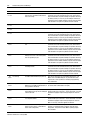
TP10
PS IN-
Power Supply In-
1:1
½ rated DC bus voltage
TP14
+EXT
External Resistor Discharge+
Not Used
-
TP16
PS IN+
Power Supply In+
1:1
½ rated DC bus voltage
TP17
-24V
-24V Power Supply
1:1
-23.7 to -24.4V DC
TP18
DGND
Digital Ground
-
-
TP19
-EXT
External Resistor Discharge-
Not Used
-
Publication 2364F-5.05 - February 2005