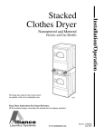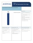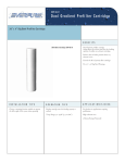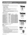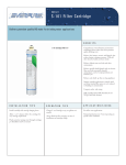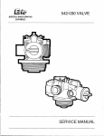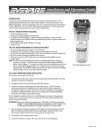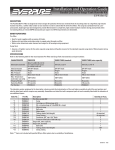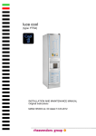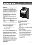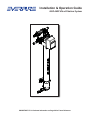
1
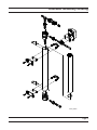
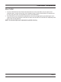
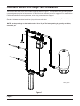
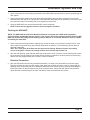
Installation & Operation Guide
HSD-440P Ultra-Filtration System
IMPORTANT: Fill in Pertinent Information on Page 28 for Future Reference
HSD-440P Table of Contents
Installation, Operation & Service Guidelines.......................................................................................................... 3
Safety, Cautions, & Warnings................................................................................................................................. 4
Assembly Drawing.................................................................................................................................................. 5
Dimensional Drawing............................................................................................................................................. 6
Introduction............................................................................................................................................................. 7
Installation.............................................................................................................................................................. 9
Back-Flush Surge Tank Installation...................................................................................................................... 12
System Start-Up................................................................................................................................................... 13
Start-Up Sanitation............................................................................................................................................... 14
Quick Start Programming Guide.......................................................................................................................... 15
Programming........................................................................................................................................................ 16
Service & Maintenance........................................................................................................................................ 23
Troubleshooting Guide......................................................................................................................................... 24
Assembly Drawing................................................................................................................................................ 26
Assembly/Replacement Parts.............................................................................................................................. 27
Appendix A - Installation/Start-Up Checklist......................................................................................................... 28
Appendix B - Warranty...........................................................................................................................Back Cover
IMPORTANT PLEASE READ:
•
The information, specifications and illustrations in this manual are based on the latest information available at the time of
printing. The manufacturer reserves the right to make changes at any time without notice.
•
This product should be installed by a plumbing professional.
•
This unit is designed to be installed on potable water systems only.
•
This product must be installed in compliance with all state and municipal plumbing and electrical codes. Permits may be
required at the time of installation.
•
If daytime operating pressure exceeds 80 psi, nighttime pressures may exceed pressure limits. A pressure reducing valve must
be installed.
•
Do not install the unit where temperatures may drop below 32°F (0°C) or above 104°F (40°C).
•
Do not place the unit in direct sunlight.
•
Do not strike any of the components.
•
Warranty of this product extends to manufacturing defects of the vessel and controller, not the membrane. Misapplication of this
product may result in failure to properly condition water, or damage to product.
•
A prefilter should be used on installations in which free solids are present.
•
In some applications local municipalities treat water with Chloramines. High Chloramine levels may damage valve components.
•
Correct and constant voltage must be supplied to the control valve to maintain proper function.
HSD-440P Installation, Operation, & Service Guidelines
IMPORTANT! READ THIS FIRST
Read this Manual thoroughly before first use.
NOTICE: Read all safety precautions before installing, operating, or servicing the Everpure HSD-440P
Ultra-filtration System.
The Everpure HSD-440P Ultra-filtration System should only be installed by qualified plumbing contractors.
Installations must comply with all local codes and state or provincial laws and regulations. Consult Everpure
Technical Service for recommendations regarding contractors qualified to properly install the system. In addition to
meeting installation codes, laws, and regulations, there are other application and usage considerations regarding
the care and maintenance of the HSD-440P Ultra-filtration System.
•
•
•
•
•
•
•
•
•
All plumbing and electrical codes must be complied with when installing this product.
Only qualified personnel should install this product.
Check the HSD-440P periodically to assure proper operation.
Do not allow the HSD-440P to be exposed to freezing temperatures. Freezing may damage the Ultra Filtration
Membrane Element.
Ensure the Ultra Filtration Membrane Element does not dry out. Opened/unused membranes should be
preserved with a 0.1% sodium bisulfite solution for no longer than 12 months.
Use Silicone lubricant sparingly on O-ring.
The HSD-440P will continue to operate as a filter during power loss. However, when power is returned after
an extended outage, the controller might need reprogramming.
Keep a copy of this manual near the water filtration system for future reference.
The HSD-440P is intended to treat only cold potable quality water. It is not intended as a permanent primary
treatment for water from a contaminated source, such as from radon, pesticides, sewage, or wastewater.
Page HSD-440P Safety, Cautions, & Warnings
Safety, Cautions, and Warnings
•
•
•
•
•
•
•
•
•
•
•
•
•
•
•
The HSD-440P must be wired and grounded according to local electrical codes to prevent the possibility of
electrical shock.
Do not modify the power supply cord.
The HSD-440P must be installed in compliance with local plumbing codes and any other applicable codes.
The HSD-440P has been designed and tested to offer reliable service only if installed by a qualified installer
and operated and maintained according to the instructions in this service manual.
For safety reasons, the HSD-440P is furnished with a low voltage power transformer to plug into a standard
electrical outlet. Do not replace this transformer with another power supply as this may cause damage to the
electronics.
Install the HSD-440P only for its intended use as described in this service manual.
Do not use corrosive chemicals in the HSD-440P.
Do not install the HSD-440P if it has a damaged cord or plug, if it is not working properly, or if it has been
damaged or dropped.
Do not immerse the power cord or plug in water.
Keep the power cord away from heated surfaces.
Turn the HSD-440P system off and disconnect from the power source before performing any service or
maintenance on the unit.
Do not plug in the controller transformer if there is water on the electrical wiring or the power supply.
Always shut off the water flow and release water pressure before cleaning or maintaining the HSD-440P.
The HSD-440P is intended for indoor use only. The power supply and controller must not be exposed to
weather elements.
The outlet used for power to the HSD-440P should be an unswitched outlet.
Page HSD-440P Assembly Drawing
61653_REVA
Page HSD-440P Dimensional Drawing
91.81 mm
3.61 in
268.41 mm
10.57 in
418.19 mm
16.46 in
326.49 mm
12.85 in
1349.35 mm
53.12 in
187.96 mm
7.40 in
61653_REVA
Page HSD-440P Introduction
The Everpure HSD-440P Ultra-filtration System is a high capacity, high flow rate, flushable water filtration system
capable of removing many types of particulates from residential and foodservice water supply installations.
This advanced “point of entry” (POE) water treatment device is designed to improve water quality in a variety of
applications and uses. Ultra-filtration membrane technology is designed to filter out suspended particles, large
dissolved molecules, and most colloids. The HSD-440P does not remove ions, dissolved minerals (hardness) or
very small organic molecules such as pesticides.
The HSD-440P requires minimal maintenance and will provide clean, better-tasting water for many years. The
system incorporates programmable automatic filter cartridge flushing which results in extended service life without
the need for frequent, routine cartridge replacement.
APPLICATIONS
The Everpure HSD-440P Ultra-filtration System may be used in a variety of applications. However, its two
primary uses have been for residential whole-house filtration and for commercial foodservice water treatment.
Because the device itself is identical for either application, this manual has been designed to cover both types of
installations. Where different information is appropriate, the manual will indicate those differences.
Residential Applications
•
•
•
Whole-house point-of-entry
Whole-house drinking water lines only (no outside hose bibs)
Custom kitchen or wet bar installations
Foodservice Applications
•
•
•
•
Foodservice applications include “point-of entry” treatment of supply water used in restaurants for food
preparation and as ingredient water.
Examples of food preparation applications include water using equipment such as steamers, combi-ovens
and commercial dishwashers.
Examples of ingredient water applications include fountain beverage and juice dispensers, coffee makers and
espresso machines, ice machines, insta-hot dispensers and drinking water spigots.
Other foodservice applications include pre-filtration to extend the service life of “point-of-use” (POU) water
filtration systems/cartridges, especially in high particulate or high turbidity locations.
Flow Capacity
Assess the home or commercial facility water usage, especially during peak demand. The standard HSD 440P is
sized for 10 gpm peak capacity flow. Water demand that exceeds peak capacity will have the effect of reducing
pressure and volume delivery at open taps or faucets.
Note: Higher flow rates above 10 gpm will require multiple units in parallel.
Page HSD-440P Introduction
Flushing Considerations
NOTE: It is important to understand the water quality and fouling potential in order to determine the type
and/or frequency of flushing when installing the HSD-440P. The HSD-440P System should be flushed on a
schedule determined by the quality of the water being treated.
Default Factory Settings:
Flush Frequency: 100 gallons
Flush Duration: 30 seconds
These settings may need to be adjusted based on the analysis for the water treated and practical experience
with fouling. In all installations, the HSD-440P is programmed to flush automatically after 24 hours without a flush,
regardless of the volume flowed. A high capacity storage tank is highly recommended when there are high service
flows and/or peak demand periods, and high turbidity. Refer to the table below for initial set up recommendations.
Table 1: Initial Recommended Flushing Parameters by Water Source and Treatment
Water Source
Pre-Treatment*
30 - 50 micros
Forward Flush
Back-Flush Surge Tank**
Flush Frequency
(Gallons Produced)
Private Well
30 micron filter
Yes
Yes
200
Private Well
High Iron
30 micron filter;
iron filter
Yes
Yes
300
Private Well
(Extreme Water)1
30 micron filter
Yes
Yes
100
Municipal Surface
50 micron filter
Yes
No
200
Municipal Well
50 micron filter
Yes
No
300
* In all cases, a 50 micron pre-filter cartridge is required to protect the HSD-440P from large particles, plumbing
debris, etc. Everpure Housing 20” BB 1” FPT connections part number DEV9104-50 with mounting bracket
WB-SS kit part number DEV3109-52 and cartridge DGD-5005 20BB part number DEV9108-37.
** A back-flush surge tank is needed to avoid fouling in these installations. Small surge part number EV9336-50.
1
Some shallow wells have serious contamination problems, high turbidity, TOC, color and taste levels.
Page HSD-440P Installation
Many water sources, particularly private wells, have higher levels of turbidity or suspended solids that can shorten
membrane life of the HSD-440P if adequate flushing is not performed. Installation of a 30-50 micron sediment
filter is optional.
A properly sized tank is required when high flow rates are encountered to meet volume demands of the service
equipment. This tank offers a volume of treated water for periods of peak flows, thereby extending service life of
the membrane. The tank needs to be sized based on the higher volume expected.
The system must be protected from possible back contamination by the installation of an air gap between the
HSD-440P drain connection and the drain line.
An Installation/Start-up Checklist is provided in Appendix A of this manual to help prompt for procedural steps
and to record useful information for future reference. Please refer to this document and have it at hand during the
installation and start-up process.
HSD-440P Location
Note the location of the water supply, drain and an unswitched electrical outlet when choosing a mounting
location. The Everpure HSD-440P is a point-of-entry device designed to treat water distributed throughout the
entire system. The installation should be located near the service water point of entry to the home or commercial
facility, but before the plumbing is split up for distribution. Ensure the outside hose bibs are not plumbed into the
HSD-440P system.
A mounting bracket has been designed to mount the HSD-440P sufficiently off the wall to accommodate
installation of a pre/post filter inline with the water inlet and/or water outlet of the system. Remember to allow for
visual access to the meter/programming controls. Do not mount the HSD-440P above any electrical equipment, or
above items that may become damaged if they get wet. Install the HSD-440P in a location that will allow for easy
service access. Service and maintenance requires access to the unit and potential removal and replacement of
the membrane element.
The HSD-440P system should be attached to a wall in a vertical orientation using appropriate mounting hardware
capable of supporting 51 pounds (23.1 kilograms). The HSD-440P’s footprint is 12” x 12”, exclusive of plumbing
connections. It is suggested that initial installation and future removal/replacement of the membrane element be
performed with the HSD-440P housing lying horizontally.
Plumbing Considerations
Follow all applicable plumbing codes when installing the HSD-440P System.
Individual installation conditions and requirements can vary greatly. A compliment of basic plumbing
interconnection fittings are included with the HSD-440P package. These fittings (see the HSD-440P Assembly
Drawing) are intended to simplify system adaptation to common installation circumstances.
NOTE: Everpure requires installation of a bypass with every HSD-440P to meet the most efficient service
over the life of the unit. Additionally, some local plumbing codes may require a bypass.
All HSD-440P housing ports (inlet, outlet, and drain) are 3/4” NPT connections.
A 10 gpm flow control fitting is included for installation on the HSD-440P inlet to ensure the most efficient
operation of the membrane. A 7 gpm flow control fitting is included for installation on the drain line to maximize
water efficiency and help assure proper flushing rates. Verify that the drain selected has adequate capacity.
NOTE: Please see Figure 1 on page 12 for proper inlet & drain identification.
Page HSD-440P Installation
Electrical Requirements
The HSD-440P controller requires a constant electrical supply to flush correctly (120 VAC) 60 Hz or (230 VAC) 50
Hz.
Additional Water Treatment Devices
It is preferable (though not required) to install the HSD-440P Ultra-filtration System ahead of softeners, iron filters,
and other similar water treatment devices, as the removal of particulates generally improves their performance
and longevity.
If an on-site chlorination system exists, the HSD-440P should be installed ahead of that system. Excess exposure
to concentrated chlorine levels risks oxidative attack on the membrane, shortening its life depending on chlorine
level, time of contact and temperature. The HSD-440P can withstand a continuous dose of 1.0 mg/L (or ppm) of
free chlorine, but continuous exposure to higher level of free chlorine or other oxidizing chemicals can shorten
Ultra Filtration Membrane Element life.
HSD-440P Assembly
1. Find an area near the installation location with a fair amount of space to lay out the components.
2. Carefully remove all components from the carton. Ensure that all parts are included and are in good condition.
3. Lay the Ultra Filtration Membrane Element housing horizontally on the floor (or other large, flat surface).
4. Attach the upper mounting bracket and timer to the Ultra Filtration Membrane Element housing.
5. Attach the flow meter, solenoid valve, and flow control fittings to the appropriate ports on the Ultra Filtration
Membrane Element housing.
6. Visually check to ensure both large o-rings on both top and bottom end caps are present before installing.
7. Insert bottom end cap (with two plugs) into the stainless steel housing. Attach the u-bolt through housing and
end cap. Next, install the cotter pin to the end with the hole and plastic cap to other end of u-bolt.
8. Drop the stainless steel spring into the bottom of the stainless steel housing, ensuring the spring is lying flat
on the bottom end cap.
9. Carefully remove the Ultra Filtration Membrane Element from its plastic bag.
NOTE: The O-rings must first be lubricated lightly with the supplied food grade Silicone. Dirt, dust,
hair, or other foreign materials cannot be in the central tube or on the connector. Visually inspect the
O-ring and sealing surfaces for cleanliness.
10. Orientate Ultra Filtration Membrane Element cartridge with the center outlet hole on top.
NOTE: The Ultra Filtration Membrane Element has one end sealed and one end open. The open end
must be on top for proper assembly.
11. Slowly feed the Ultra Filtration Membrane Element into the top of the membrane housing. DO NOT DROP
THE Ultra Filtration Membrane Element INTO THE HOUSING. THIS CAN DAMAGE THE Ultra
Filtration Membrane Element.
12. Install top end cap with adapter into the stainless steel housing. When installing the end cap containing the
adapter, it must be centered to fit into the opening in the center of the membrane element.
13. Once the adapter and end cap are in place, attach the u-bolt through the stainless steel housing and end cap.
Next, install the cotter pin to end with the hole and plastic cap to the other end of the u-bolt.
14. Connect the solenoid valve and flow meter to the cables already attached to the timer. Push the solenoid
cable socket onto the solenoid and fasten the holding screw. The flow meter cable has a flat side
corresponding to the port molded into one side of the flow meter. Insert the meter cord into the port and push
it until it snaps into place.
Page 10
HSD-440P Installation
Mount To Wall
1. Once the HSD-440P with Ultra Filtration Membrane Element is fully assembled, carry the system to the
selected location. Conduct a final check of the installation location, paying careful attention to clearances for
the inlet, drain, and outlet, and accessibility for service and maintenance.
2. The HSD-440P may be mounted fully suspended onto the wall at an appropriately accessible height. Local
codes may require some clearance under the unit. Attach the HSD-440P to the wall with four adequately sized
bolts for the mounting brackets.
NOTE: The bracket height may be adjusted along the filter housing.
Page 11
HSD-440P Back-Flush Surge Tank Installation
Connect the HSD-440P to the service water supply as shown in Figure 1. It is required that the plumbing include
a system bypass provision for future service. A 30 to 50 micron sediment pre-filter is suggested. For ease of Ultra
Filtration Membrane Element replacement, union fitting connections are supplied.
The back-flush surge tank (optional) should be sized to provide adequate volume for flushing. The back-flush tank
should be installed on a line branched off (Tee) before the flow meter.
NOTE: Set the precharge on the bladder tank to 12 to 15 psi. The factory setting is generally set higher,
around 30 psi.
42334_REVA
Figure 1
Page 12
HSD-440P System Start-Up
1. Open a tap or faucet in the building downstream of the HSD-440P to permit water to flow into and through the
filter system.
2. Slowly open the filter system inlet valve about half way and allow the inlet water to purge air from the unit.
Maintain water flow until all air is purged out of the HSD-440P and piping and no sputtering occurs at the open
tap. Open other taps in the building until air is purged from those lines.
3. Open the HSD-440P inlet valve and all other filter valves completely.
NOTE: Ensure that any bypass valves are in the non-bypass condition.
Flushing the HSD-440P
NOTE: The HSD-440P Ultra Filtration Membrane Element is shipped with a USP Grade (ingestible)
glycerin/sodium metabisulfite storage solution. This solution should be completely flushed from the HSD440P and downstream piping before allowing product water to be consumed. Ensure the drain is capable
of handling the water flow.
1. Open a tap or faucet with good drain capacity fully, and let the water run 30 minutes. During this time, close
and re-open the tap three times (this start/stop helps flush the solution). To avoid flooding, do not leave an
open tap unattended.
TEST: Fill a clear glass at full flow from the tap used for flushing. Observe whether any foaming
occurs in the glass. If it does, the storage solution has not been fully flushed out.
2. After the main flushing, open and flush other taps or faucets for a full 3 minutes. Use the foaming test at each
tap to ensure thorough flushing. Ensure that all new plumbing connections, the three ports from the housing,
and the two end cap perimeters have no leaks. Correct as needed.
Electrical Connection
3. After the HSD-440P has been fully plumbed and flushed, it is ready to be connected into its power supply.
Plug the controller plug into its power supply outlet. Open the controller enclosure cover by unscrewing the
retaining screw and pivoting the cover downward. Manually initiate a flush cycle by pressing and holding the
Extra Cycle button on the front (bottom left) of the controller panel. Ensure the filter system solenoid valve
opens and that a robust flow goes to drain, and that the drain can handle the flow volume.
Page 13
HSD-440P Start-Up Sanitation
Sanitization
It is suggested that the HSD-440P and all included plumbing be sanitized to eliminate possible contamination that
may have occurred during installation. Unscented household chlorine bleach can be used to sanitize the system.
Approximately 1 ounce (capful) of bleach is sufficient to sanitize the HSD-440P. The total amount of bleach
needed depends on the amount of plumbing installed downstream of the filter system.
Procedure (with Prefilter)
1. Close the HSD-440P water inlet valve and open the tap, faucet or drain valve closest downstream of the
system. Allow the system to depressurize until water flow stops.
2. Introduce chlorine through the prefilter.
3. Open a cold water tap as far as possible from the HSD-440P and slowly open the filter system water inlet
valve. Allow water to flow through the HSD-440P and outlet piping until the smell of bleach is present at the
tap.
4. Close the tap and allow the HSD-440P to stand (with water, but without flow) for at least 15 minutes. This
permits the bleach solution to sanitize the filter system and distribution piping.
5. After 15 minutes without water flow, open all taps/faucets and flush with fresh inlet water until the smell of
bleach is gone. Close all taps/faucets to complete the sanitation process.
Now, proceed with the programming instructions that follow to set up the controller.
Alternate Procedure (No Prefilter)
1. Close the HSD-440P water inlet valve and open the tap, faucet or drain valve closest downstream of the
system. Allow the system to depressurize until water flow stops.
2. Disconnect the filter system inlet union fitting and introduce the liquid bleach (1 ounce or capful) into the filter
inlet line. A short length of flexible hose or tubing inserted into the line and extended vertically can be used to
simplify pouring the liquid bleach into the line. Be careful not to spill bleach onto clothing or skin. Reconnect
the filter system inlet union fitting.
3. Open a cold water tap as far as possible from the HSD-440P and slowly open the filter system water inlet
valve. Allow water to flow through the HSD-440P and outlet piping until the smell of bleach is present at the
tap.
4. Close the tap and allow the HSD-440P to stand (with water, but without flow) for at least 15 minutes. This
permits the bleach solution to sanitize the filter system and distribution piping.
5. After 15 minutes without water flow, open all taps/faucets and flush with fresh inlet water until the smell of
bleach is gone. Close all taps/faucets to complete the sanitation process.
Proceed with the following programming instructions to setup the controller.
Page 14
HSD-440P Quick Start Programming Guide
Basic Programming Quick Reference Guide
1) Plug in system
2) Display will alternate between Time and Flush Volume (Default 100 gallons)
3) Set time to 12:01 PM by moving the “Set up button” and/or “Set down button”
4) Then press and hold the “Program” button to for 5 seconds to enter programming menu
5) Once in the programming menu, continue to press the “program” button to toggle through the various settings listed below
6) Use the “Set up button” and/or “Set down button” to adjust the setting as desired
* In typical application only Flush Duration, Flush Volume, and Time of day would need adjustment
Default Settings
1--- 0.5
Flush Duration- minutes (eg. 30 seconds = 0.5)
Fr --- .0
Flow rate
d --- 0
Days since last regeneration
E ---0
Prior volume used
Pd ---0
Previous day usage
y --- OFF
Time Aux off
n --- OFF
Chem pump off
A --- 1
Time override - days (default 1 day)
b --- 100
Flush Volume - gallons (default 100 gallons)
u --- 1
US Gallons
7 --- 2
Meter immediate flush
F --- 6
Allows for pulse setting of flow meter
F - 6 - 80.0
80 pulses per gallon
PL --- OFF
Lock OFF
NOTE: A 9 Volt battery (not supplied) is required for Time of Day back up.
Page 15
HSD-440P Programming
Timer Display
Service
Time
Reserve Totalizer Meter
Regen Lockout Volume Program Flow Sensor
Remaining
Rate
Regeneration
Signal
Low Battery
Program Display Indicator
Water Hardness
System Capacity
Regeneration Time
Extra
Cycle
Totalizer
Flow
Rate
Program
S
E
T
Set Down
Button
Page 16
Extra Cycle Button
Program Button
Set Up Button
HSD-440P Programming
Programming
1. During cold weather, it is recommended that the installer warm the system up to room temperature before
operating.
2. In normal operation the Time of Day and Volume Remaining Displays will alternate being viewed. Set the
Time of Day Display by pressing the Set Up or Set Down buttons to the correct time.
Example:
12:59 A.M.
(System in Service)
3. The Volume Remaining Display is the volume of water (in gallons) remaining prior to flushing. Without any
water usage the Meter Arrow should be either off or on but not changing. Open a tap. The Meter Arrow should
begin flashing at a rate that varies with flow rate. Close the tap after 3-5 gallons of water flow.
Example:
0 Gallons of Water
Remaining
(System in Service)
(Water Flowing, Meter
Arrow Flashing)
Example:
125 Gallons of Water
Remaining
(System in Service)
(No Water Flow)
Controller Operation During a Flush Cycle
1. Manually initiate a flush cycle and allow water to run to the drain. To initiate a flush, press and release the
Extra Cycle button. The system will go into flush mode immediately.
A. During Flushing: During flushing, the system will display the time remaining.
Example:
(System is sending
0.6 minute regen signal)
(Regeneration Arrow)
Regeneration
Signal
B. Pushing the Set Up or Set Down button during the flush cycle will adjust the time remaining in that cycle.
The programmed flushing time will not be changed.
C. After the flush cycle, the system returns to in service and will resume normal operation.
2. A 9V alkaline battery is recommended to be installed at all times for proper controller operation. The system
will indicate when the battery needs to be replaced by turning on the Low Battery LED.
NOTE: A battery is not necessary for the controller to function and the Ultrafilter to operate properly. Only
the clock will be affected, when a power outage occurs. The flush settings will remain unaffected.
Page 17
HSD-440P Programming
Control Operation During Programming:
The system will only enter the Program Mode when it is in service and operating on line power. While in the
Program Mode the system will continue to operate normally, monitoring water usage and keeping all displays up
to date. System programming is stored in memory permanently with or without line or battery backup power.
Keypad Operation:
Extra Cycle Button
Pushing this button will initiate a flush independent of the actual system conditions. This extra flush will occur
immediately.
Totalizer/Flow Rate Button
This button is used to view the Totalizer and Flow Rate Displays. Pressing the button once will display flow rate.
Pressing the button again will display the total accumulation of water flow through the system since it was last
reset. Pressing the button once more will return the display to the Time of Day or Volume Remaining screen. The
Totalizer display is reset by pressing and holding the Totalizer button for 25 seconds. During the 25 seconds, the
Totalizer Arrow will flash to indicate that the display is being reset properly.
Program Button
This button is used by the installer to program those settings indicated on the front panel by red LEDs.
Set Up Button
This button is used to set the current time of day, adjust time remaining in a regeneration cycle step, and in
system programming. The Set Up button will increment a display setting.
Set Down Button
This button is used to set the current time of day, adjust time remaining in a regeneration cycle step, and in
system programming. The Set Down button will decrement a display setting.
Low Battery Indicator
When the system is operating on line power, this red LED will turn on whenever the 9V alkaline battery (not
included) used for memory backup needs to be replaced. The battery is stored against the valve backplate. In
the event of a power outage, the battery will maintain current operating displays for approximately 24 hours at
maximum battery capacity.
Page 18
HSD-440P Programming
Changing Flushing Duration
1. While the system is in service, press and hold the Program button for 5 seconds.
2. The Flush Duration Time will be displayed. Use the Set Up and Set Down Set Buttons to adjust the time.
Note: The time can be set in 0.1 minute increments.
Example:
(Timer is sending 0.6
minute regen signal)
(Regeneration arrow on)
Controller Programming
1. Using the Set Up and Set Down buttons, adjust the time on the controller to 12:01 P.M.
2. Push and hold the Program Button for 5 seconds.
3. The first display is the Flush Duration Time. The Flush Duration Time can also be adjusted on this display,
using the Set Up and Set Down buttons. To skip this display, press the Program button.
Example: 0.5 minutes [1----0.5]
1. Flow Rate Display (Fr)
The first display viewed is the current flow rate of treated water through the system. The unit of measurement
used is gallons/liters per minute.
Example: 8.5 Gallons Per Minute [Fr - - - 8.5]
2. Days Since Last Regeneration Display (d)
Press the Program button. The next display viewed is not an option setting. This display is used as an aid
to the service person in diagnosing a system malfunction. The number of days since the last regeneration is
recorded in this display by the control. This display is identified by the letter “d” in the first digit.
Example: 4 days [d - - - - - 4]
3. Prior Service Volume Used Display (E)
Press the Program button. The next display viewed is not an option setting. This display is used as an aid to
the service person in diagnosing a system malfunction. The amount a water used since the last time the filter
was in service is recorded in this display by the control. The unit of measurement used is gallons/liters/cubic
meters.
Example: 850 Gallons - [ E - - - 850]
4. Previous Days Water Usage Display (Pd)
Press the Program button. The next display viewed is not an option setting. This display is used as an aid to
the service person in diagnosing a system malfunction. The previous days water usage (in gallons/liters/cubic
meters) is recorded in this display by the control.
Example: 200 gallons - [ P d - - 200 ]
Page 19
HSD-440P Programming
5. Timed Auxiliary Output Programming (y) (r) (n)
Press the Program button. The next 3 displays viewed are part of a series of option settings used to program
the optional relay output. These displays will not be viewed if the optional relay output is not installed. The first
two settings (y and r) turn the output on/off during regeneration only. The third (n) turns the output on during
service only, when a set volume of water used has accumulated. This setting will not be viewed on nonmetered systems.
NOTE: When more than one of these settings is used, it will be up to the operator to supply the
switching logic necessary to operate two or three separate pieces of equipment at a time from a
single relay output.
6. Timed Auxiliary Output Window #1 Setting (y)
This option setting consists of two displays. The first display is used to set the turn on time of the output,
referenced to the start of backwash. The second display is used to set the output turn off time, referenced
again to the start of backwash. An OFF setting cancels this setting. A set on time with a set off time of S will
turn the output off at the start of service. All settings are in minutes and output timing is synchronized with
regeneration cycle timing.
Examples:
Activate output at start of Step #1/Deactivate after 10 minutes [ y - - - - - 0 ]
[ 10.0 ]
Cancel setting[ y - - -OFF ]
(Start Time Display)
(Stop Time Display)
— Use the Set Up and Set Down buttons to adjust these settings.
7. Timed Auxiliary Output Window #2 Setting (r)
Press the Program button. This option setting consists of two displays. The first display is used to set the turn
on time of the output, referenced to the start of backwash. The second display is used to set the output turn
off time, referenced again to the start of backwash. An OFF setting cancels this setting. A set on time with a
set off time of S will turn the output off at the start of service. All settings are in minutes and output timing is
synchronized with regeneration cycle timing.
Examples:
Activate output 15 mm after the start of Step #1/Deactivate
when in service
[ r - - - 15.0 ]
[------S]
Cancel setting[ r - - -OFF ]
8. Chemical Pump Output (n)
Press the Program button. This option setting consists of two displays. The first display is used to set the turn
on time (in minutes) of the output. The second display is used to set the volume of water flow at which the
output will turn on.
Examples:
Activate output 1.0 mm. after every 200 gallons
[ n - - - - 1.0 ]
[ 200 ]
Activate output 1 second after every 200 gallons
[ n - - - - - -P] (Pulse Mode)
[ 500 ]
Cancel setting[ n - - - OFF ]
— Use the Set Up and Set Down buttons to adjust these settings.
Page 20
HSD-440P Programming
9. Regeneration Day Override (A)
Press the Program button. The next display is used to set the Regeneration Day Override Option Setting. The
Regeneration Day Override Option Setting sets the maximum amount of days that the filter can be in service
without a regeneration, regardless of water usage or the lack of a sensor signal. Regeneration begins at the
set regeneration time or at the previous regen time. An OFF setting will cancel this option with all regeneration
types except Timeclock Regeneration. A day override setting is required for timeclock regeneration systems.
Examples: Override every 7 days
[A-----7]
Cancel setting[ A - - -OFF ]
— Use the Set Up and Set Down buttons to adjust these settings.
10.Volume Override (b)
Press the Program button. The next display viewed is used to set the maximum amount of water that can be
used before a regeneration cycle is called for. When this feature is used with delayed regeneration systems, it
is up to the programmer to determine a reserve capacity. The control will no longer keep track of the reserve
capacity. This option is typically used to bypass standard reserve or capacity calculations made by the control.
Examples:Override every 700 gallons
Override cancelled
[ b - - - 700 ]
[ b - - OFF ]
— Use the Set Up and Set Down buttons to adjust these settings.
11.US/Metric Display Format (U)
Press the Program button. This display is used to set the desired display format for the timer to use.
There are five possible settings:
The U.S. Format uses gallons for volume and gallons per minute for flow rate related data/displays with a
12 hour timekeeping format. Option settings P and 8 as well as Regeneration Types #7 and #8 will not be
displayed.
Example: [U - - - - - 1 ]
The European Metric Format uses liters for volume and liters per minute for flow rate related data/displays
with a 24 hour timekeeping format. Example: [U - - - - - 2 ]
The Standard Metric Format uses liters for volume and liters per minute for flow rate related data/displays
with a 24 hour timekeeping format. Option settings P and 8 as well as Regeneration Types #7-8 will not be
displayed.
Example: [U - - - - - 3 ]
The Cubic Meter Metric Format uses m3 for volume and liters per minute for flow rate related data/displays
with a 24 hour timekeeping format. Regeneration Types #7 and #8 will not be displayed.
Example: [U - - - - - 4 ]
The Japanese Metric Format uses liters for volume and liters per minute for flow rate related data/displays
with a 24 hour timekeeping format. Option settings P and 8 as well as Regeneration Types #7-8 will not be
displayed.
Example: [U - - - - - 5 ]
— Use the Set Up and Set Down buttons to adjust these settings.
Page 21
HSD-440P Programming
14.Program Lock (PL)
Press the Program button. This display is used to prevent certain displays from being viewed or set.
There are two possible settings:
Examples:[ PL - - OFF ] Lock Canceled
[ PL - - - ON ] Lock Active
Settings Able To Be Reset With Lock Active:
Water Hardness
Water Hardness After Mixing Valve
Regeneration Time
Time Of Day
Displays Able To Be Viewed With Lock Active:
Flow Rate Display
Days Since Regeneration Display
Prior Service Volume Used Display
Reserve Capacity Display
Previous Days Water Usage Display
Unlocking Programming:
The only way to deactivate this feature is to push and hold the Program button for 25 seconds. This
procedure will unlock the control and permit all valid program settings to be viewed and reset as needed.
— Use the Set Up and Set Down buttons to adjust these settings.
Exiting This Option Setting Level
Push the Program button once per display until all have been viewed.
Resetting Permanent Programming Memory
Push and hold the Program button for 50 seconds. This procedure will erase this and all previous display settings
and reset them to default values. Control programming will then have to be reset as necessary.
Page 22
HSD-440P Service & Maintenance
Help Contact
If problems are experienced with the installation or operation of the HSD-440P, refer to the Troubleshooting
Guide in this manual first for assistance. If the Troubleshooting Guide does not help resolve your problem, contact
Everpure Technical Service at 1-800-323-7823 or 1-630-307-3000 for in-depth assistance.
Prefilter Changes
The 30 to 50 micron prefilter should be changed per the manufacturer’s recommendation or when supply water
flow to the HSD-440P System becomes too restricted for adequate filtered water production. Typically, the
cartridge should be changed when a decrease in pressure is noted, or after 6 months of service, whichever
occurs first.
NOTE: Typically, the cartridge should be changed when the outlet dynamic (flowing) pressure falls below
25 psi on the pressure gauge, or when the outlet flow becomes too low or restrictive.
Ultra Filtration Membrane Element Replacement
The HSD-440P Ultra-filtration System membrane element is designed to last for a number of years (3-5 typical)
without replacement under normal operating conditions and with proper installation and maintenance procedures.
When filtered water flow rates or volumes fall below requirements and can not be restored by normal flushing, the
membrane element will need to be replaced.
Use the bypass valve (if installed) to bypass service water around the system.
1. Run a manual flush until water no longer comes out of the drain port.
2. Unplug the power cord leading to the system and gently disconnect the cord leading to the flow meter.
3. Slowly disconnect the three unions starting with the union located closest to the floor (this will allow any
remaining water to drain from the system).
4. Loosen the mounting bolts which fasten the HSD-440P System to the wall.
5. Lift the system up slightly and pull it away from the wall, laying the housing horizontally on the floor.
6. Remove the cotter pin and plastic cap from the ends of each u-bolt. Pull u-bolt away from end cap and
stainless steel housing. Pull end caps and adapter with top end cap.
7. Slide the old Ultra Filtration Membrane Element out of the membrane housing (both end caps may need to be
removed so the element can be pushed out of the housing). Clean and rinse the housing as required, using
only a mild, nonabrasive detergent.
8. Lubricate the O-rings sparingly with Silicone. Replace the end cap on the bottom housing. Drop the stainless
steel spring into the bottom of the stainless steel housing, ensuring the spring is lying flat on the bottom end
cap.
9. Orientage Ultra Filtration Membrane Element with the center outlet hole on top. Gently slide the membrane
cartridge into the housing. DO NOT DROP THE MEMBRANE ELEMENT INTO HOUSING-THIS COULD
DAMAGE THE MEMBRANE ELEMENT. The element should line up with the lower adaptor. Push the
element firmly into place.
10. Gently and firmly slide the top adapter with o-rings into the Ultra Filtration Membrane Element’s center tube,
and fasten the end cap with the u-bolt.
11. Remount HSD-440P against the wall and reattach plumbing.
12. Place the unit back into service. Before using system, perform flushing and sanitizing procedures as
described in the installation section of this manual.
Page 23
HSD-440P Troubleshooting Guide
Problem
Possible Cause
Correction
1. No lights or display on controller.
A. No power to the system.
B. Faulty controller circuitry or
display module.
A. Plug the system controller in.
B. Check/correct power supply to outlet.
C. Contact your Everpure dealer for
service.
2. There is no product water flow
from the filter.
A. Bypass valves are not in
the correct positions to allow
water flow, or supply water is
unavailable.
A. Restore inlet water supply to system.
B. Prefilter cartridge (if present) B. Replace or clean the filter cartridge.
is plugged.
3. There is low flow or pressure out
of the filter.
4. System is flushing continuously.
5. System is not flushing.
6. Meter is not reading flow.
Page 24
C. UF membrane is fouled.
C. Contact your Everpure dealer for
service.
A. Unit is in flushing mode.
A. Wait for flush to end. If desired, have
a pressure tank installed after system
to maintain pressure during flush. If
flushing continuously, see #4 below.
B. Unit is not flushing
frequently enough.
B. Decrease the volume between
flushes, and/or increase the flushing
time.
C. Inlet water pressure is too
low.
C. Boost the inlet water pressure
D. Cartridge in prefilter is
plugged
D. Replace or clean the filter cartridge
E. UF membrane is fouled
E. Contract your Everpure dealer for
service
A. Drain solenoid valve
remains open.
A. Replace the drain solenoid valve.
B. System controller circuit
board is sending continuous
flushing command.
B. Contact your Everpure dealer for
service
A. The system is not plugged
in.
A. Plug the system controller in.
B. Drain solenoid valve
remains closed.
B. Replace the solenoid valve.
C. Meter is not registering flow.
C. Check the connection of meter cable
to the meter. Secure if necessary.
D. System controller circuit
board is not sending flush
signal.
D. Contact your Everpure dealer for
service.
A. Meter cable is not secured
to the meter body.
A. Check the connection of meter cable
to the meter. Secure if necessary.
B. Meter or controller are
malfunctioning.
B. Contact your Everpure dealer for
service.
HSD-440P Troubleshooting Guide
Problem
Possible Cause
Correction
7. Water has an unpleasant taste
and/or foam.
A. Unit has not been flushed
sufficiently at startup.
A. Open all drains, and let the water
flow for 20 minutes.
8. Water leaks at the end of the
filter cartridge after changing
cartridge.
A. Cartridge end connections
are not tight enough.
A. Tighten with wrench if necessary.
B. O-rings are not properly
lubricated.
B. Lubricate O-rings.
C. O-rings are cut, or
deformed.
C. Replace O-rings.
Page 25
HSD-440P Assembly Drawing
61653_REVA
Page 26
HSD-440P Assembly/Replacement Parts
Contact your Everpure dealer for membrane elements or system replacement parts.
Item No. Quantity
Part No.
Description
1...................1.......................EV312534 (42323)................ Stainless Steel Vessel Assy, U440, Everpure
2...................1.......................EV312536 (61592-02)........... UF Filter Element Assy, 4”
3...................1.......................EV312539 (61637)................ Adapter, UF Filter
4...................2.......................EV312591 (15468)................ O-ring, -118, Injector
5...................1.......................EV312538 (42336)................ Spring, SS Vessel, U440
6...................2.......................EV312532 (41972)................ Bracket, Mounting, UF Filter
7...................2.......................EV312550 (41976)................ Saddle & Clamp Assy
8...................1.......................EV312535 (61592-01)........... UF Filter Timer Assy, ET
...................1.......................EV312592 (61592-03)........... Timer Assy, ET, UF Filter, 230V EU
...................1.......................EV312593 (61592-04)........... Timer Assy, ET, UF Filter, 230V AU
9...................1.......................EV312594 (16650)................ Fitting Kit, Inlet, U440
10..................1.......................EV312544 (60700-10)........... DLFC, 3/4”F x 3/4”F NPT, 10GPM
11..................1.......................EV312595 (61651)................ Fitting Kit, Outlet, U440
12..................1.......................EV312533 (61560-01)........... Assy, In-line Meter, 3/4” NPT
13..................1.......................EV312856 (61652)................ Fitting Kit, Drain, U440
14..................1.......................EV312537 (42106)................ Bracket, Solenoid, 1/2” NPT, NC
15..................1.......................EV312545 (60699-70)........... DLFC, 3/4”F x 3/4”F NPT, 7.0 GPM, Brass
*16.................2.......................EV312606 (42557)................ Bracket, Mounting, Meter Assy
*Item not shown
Page 27
APPENDIX A – HSD-440P Installation/Start-Up Checklist
Use this form to record initial system hardware, site conditions and controller programming information. Retain a
copy for future reference. Fill in the appropriate data, if available.
Installer: ________________________
Checklist of Steps
Installation Location: ______________________
1.
Water demand assessed ___
System Model/Serial Number: ______________
2.
Water conditions considered ___
3.
Flushing requirements determined ___
4.
Installation location allows access to membrane ___
5.
Mounting provision accommodates system weight ___
6.
Listed components/fittings present ___
7.
Inlet service water accessible ___
8.
Electrical power accessible ___
9.
Other water treatment devices considered ___
Water Source: ___________________________
Water Analysis:
Turbidity: _________________
TOC: ____________________
DOC: ____________________
Total Iron: ________________
Tannins: _________________
10. Loose components assembled to system ___
11. System securely mounted ___
12. Solenoid valve/flow meter signal connections ___
13. Plumbing connections completed ___
14. Initial flush w/o leaks ___
Pretreatment Installed: ___________________
Back-flush Tank Installed: Yes _____ No _____
Back-flush Tank Precharge: _____ psi
Set Volume Between Flushes: ____________
15. Electrical power connected ___
16. System sanitized ___
17. Back-up battery installed in controller ___
18. Controller display okay ___
19. Time of day set ___
20. All programming steps completed ___
Set Flushing Duration: __________________
21. Program displays cycled through to beginning ___
Initial Product Water Flow Rate: ___________
22. Program Mode exited; time restored ___
Other Program Details: ___________________
______________________________________
24. Installation/Set-Up information entered onto form ___
Notes:
________________________________________
________________________________________
________________________________________
________________________________________
________________________________________
________________________________________
Page 28
23. Proper operation verified ___
Notes
Page 29
Notes
Page 30
Notes
Page 31
LIMITED WARRANTY
COMMERCIAL WATER TREATMENT EQUIPMENT
You have just purchased one of the finest water treatment units made. As an expression of our confidence in Everpure products,
this product is warranted against defects in material and workmanship to the original end-user when installed in accordance with
Everpure specifications. The warranty period commences from the date of shipment from manufacturer and is administered as
follows:
For a period of ONE YEAR Ultra Filtration Membrane Element*
For a period of THREE YEARS The entire system (excluding replaceable elements)
*This is for material & workmanship, not filter or water treatment cartridge life.
The unit must be used in operating conditions that conform to Everpure’s recommended design guidelines. This warranty will not
apply if the unit has been modified, repaired or altered by someone not authorized by Everpure.
If a part described above is found defective within the specified period, you should notify Everpure technical service at the phone
number listed below. Any part found defective within the terms of this warranty will be repaired or replaced (at Everpure’s discretion)
by your local dealer or Everpure technical service. You pay only freight from our factory and local dealer charges. Any repaired or
replaced warranty item will be incorporated under the original warranty terms of the existing system.
We are not responsible for damage caused by accident, fire, flood, freezing, Act of God, misuse, misapplication, neglect, oxidizing
agents (such as chlorine, ozone, chloramines and other related components), alteration, installation or operation contrary to
our printed instructions, or by the use of accessories or components which do not meet Everpure’s specifications. Refer to the
specifications section in the Installation and Operating manual for approved application parameters.
Our product performance specifications are furnished with each water treatment unit. TO THE EXTENT PERMITTED BY
LAW, EVERPURE DISCLAIMS ALL IMPLIED WARRANTIES, INCLUDING WITHOUT LIMITATION WARRANTIES OF
MERCHANTABILITY AND FITNESS FOR PARTICULAR PURPOSE; TO THE EXTENT REQUIRED BY LAW, ANY SUCH IMPLIED
WARRANTIES ARE LIMITED IN DURATION TO THE PERIOD SPECIFIED ABOVE FOR THE ENTIRE WATER TREATMENT
UNIT. As a manufacturer, we do not know the characteristics of your water supply or the purpose for which you are purchasing this
product. The quality of
water supplies may vary seasonally or over a period of time, and your water usage rate may vary as well. Water characteristics can
also differ considerably if this product is moved to a new location. For these reasons, we assume no liability for the determination
of the proper equipment necessary to meet your requirements, and we do not authorize others to assume such obligations for
us. Further, we assume no liability and extend no warranties, express or implied, for the use of this product with a non-potable
water source or a water source which does not meet the conditions for use described in the owner’s guide or performance data
sheet for this product. OUR OBLIGATIONS UNDER THIS WARRANTY ARE LIMITED TO THE REPAIR OR REPLACEMENT (AT
EVERPURE’S DISCRETION) OF THE FAILED PARTS OF THE WATER TREATMENT UNIT, AND WE ASSUME NO LIABILITY
WHATSOEVER FOR DIRECT, INDIRECT, INCIDENTAL, CONSEQUENTIAL, SPECIAL, GENERAL OR OTHER DAMAGES.
Some states do not allow the exclusion of implied warranties or limitations on how long an implied warranty lasts, so the above
limitation may not apply to you. Similarly, some states do not allow the exclusion of incidental or consequential damages, so the
above limitation or exclusion may not apply to you. This warranty gives you specific legal rights, and you may also have other rights
which vary from state to state. Consult your telephone directory for your local independently operated Everpure dealer, or write
Everpure for warranty and service information.
For sales, replacement components, and service, contact your Everpure dealer or:
Everpure, LLC: 1040 Muirfield Drive • Hanover Park, Illinois 60133 • 800.323.7873
In Europe: Toekomstlaan 30 • B-2200 Herentals, Belguim
In Japan: Hashimoto MN Bldg. 7F • 3-25-1 Hashimoto Sagamihara-Shi • Kanagawa 229-1103, Japan
Printed in U.S.A.
P/N 42509 Rev. A
Technical Service
800.942.1153
www.everpure.com