1
Installation Instructions:
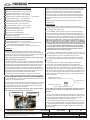
Air Cleaner: It is recommended that a dry element air cleaner be used.
NOTE: Fueling cannot be guaranteed if an oiled element type air
cleaner is used.
ECM
The Engine Control Module (ECM) is environmentally sealed and can be
mounted underhood, however, avoid extremely hot locations (exhaust,
Oxygen Sensors: NOTE: It is critical that the Oxygen Sensors are
etc.) or high splash areas. It is not recommended that the EMC be
mounted per the instructions below. The exhaust system MUST be
mounted directly to the engine.
properly sealed – any leak near the sensors (upstream or downstream) can cause incorrect operation of the fuel control system.
Accelerator Pedal
Vehicle performance and/or driveability may be affected if sensors
Mount the accelerator pedal per the following dimensional guidelines,
are not mounted as recommended or if an exhaust leak exists. Leak
check the exhaust system to ensure adequate sealing (even small
that the pedal is securely mounted to the vehicle. A grommet is required leaks can affect fuel control).
in any sheet metal hole that the harness routes through to avoid wire
Oxygen Sensors should be mounted in the collector area of the exdamage.
haust manifolds in a location that allows exhaust from all cylinders to
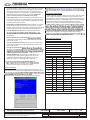
ACCELERATOR PEDAL ASSEMBLY MINIMUM SPACING GUIDELINES
be sampled equally (stock exhaust manifolds include a mounting boss
for the oxygen sensors). Be sure the connectors and wiring are routed
2.5”
away from high heat areas. The oxygen sensors should be mounted
with the sensor tip pointing between horizontal and fully downward – do
2”
not mount with the tip oriented upward. Weld in the mounting bosses
Brake Pedal Brake
supplied (7/8” hole) if using headers.
Pedal
Accelerator
Pedal
Exhaust Manifolds: It is recommended that you use the provided exhaust manifolds or similar LS Engine style Exhaust Manifolds.
.75”
Accelerator
Pedal
Side View
Positive Crankcase Ventilation System (PCV)
How to set up your PCV system:
There are two ports on the engine that make up the PCV system. The
ports on the engine are:
Tunnel /
Console
Front View
Mass Air Flow (MAF) Sensor
NOTE: It is critical that the MAF sensor is mounted per the
instructions below. Vehicle performance and/or driveability may be
affected if it is not mounted as recommended.
1) Left rear (driver side) valve cover.
2) Top center of the inlet manifold.
The ports with silver tubes may look simple but, they should not be
place of a PCV valve of earlier designs.
the supplied MAF sensor mounting boss. The induction system should
be 4 inches in diameter and have a minimum straight section 6 inches
in length. Mount the MAF sensor in the middle of the straight induction
section, ensuring that the middle of the mounting boss is at least
10 inches from the throttle body.
The MAF sensor must be oriented correctly in the induction
Be sure to weld the mounting boss correctly – the sensor will only
mount one way in the boss (see diagram).
Weld the boss in place before installing the sensor. When installed in
the vehicle, the MAF sensor should be mounted with the connector end
pointing between horizontal and fully upright – do not mount with the
connector oriented downward.
connection must be within the engines air cleaner system and must be
between the MAF (Mass Air Flow Sensor) and engine’s throttle body.
The engine burns the air that enters the PCV system so, if the fresh air
port is prior to the MAF then, this air will enter the engine without being
measured by the MAF and adverse engine operation may occur.
Power Brake Booster Vacuum Source: The vacuum port for the Brake
Booster is a plug in the rear of the intake manifold. If you need the
vacuum source for your brake system the plug needs to be removed and
Oil Pressure Sensor:
pressure sensor you can purchase sensor p/n 12616646 or equivalent.
This is an optional connection and is not required for your control system
to operate.
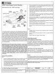
MAF SENSOR MOUNTING GUIDELINES
MINIMUM 6” STRAIGHT SECTION
4”
TO AIR FILTER
TUBE
There is one fresh air port which is on the front of the right (passenger
side) valve cover. Again this is a silver tube that faces forward on the
MAF SENSOR MOUNTING BOSS
ns
Se
o r M o u nt i
ng
ea
Ar
MA
F
MINIMUM 10” FROM THROTTLE BODY
Engine Wiring Harness: The following lists the engine and vehicle
side connections. Optional circuits are described in the ‘System
Features’ section below: NOTE: A Malfunction Indicator Lamp (MILsometimes called a “service engine soon” light) is mounted inside
the fuse/relay center. A redundant MIL output is also available in
the harness near the pedal module connector. It is recommended
that a MIL also be installed in a visible location in the passenger
compartment. This circuit requires any 12v low current light and
an ignition 12v power source. The ECM MIL output supplies the
ground for the circuit.
UP
TITLE
LS Series Crate Engine Control System
REV 28JN12
ALL INFORMATION WITHIN ABOVE BORDER TO BE PRINTED EXACTLY AS SHOWN ON 8 1/2 x 11
WHITE 16 POUND BOND PAPER. PRINT ON BOTH SIDES, EXCLUDING TEMPLATES.
TO BE UNITIZED IN ACCORDANCE WITH GM SPECIFICATIONS.
DATE
PART NO.
19171935
REVISION
SHEET
2
OF
23
AUTH