1
ORDER NO. MAC9609040C2
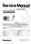
Service Manual
Room Air Conditioners
CS-G90KE / CU-G90KE
CS-G120KE / CU-G120KE
Contents
●
●
●
●
●
●
●
●
●
●
●
●
●
●
Features .......................................................... 1
Functions ................................................... 2 – 6
Product Specifications ............................. 7 – 10
Dimensions ............................................ 11 – 12
Refrigeration Cycle Diagram ......................... 13
Block Diagram ............................................... 14
Wiring Diagram ...................................... 15 – 16
Operation Details ................................... 17 – 48
Installation Information .......................... 49 – 50
Servicing Information ............................. 51 – 62
Technical Data ....................................... 63 – 64
Exploded View ......................................... 65, 67
Replacement Parts List ........................... 66, 68
Electronic Parts List ............................... 69 – 70
1996 Matsushita Air-Conditioning Corp. Sdn. Bhd.
All rights reserved. Unauthorized copying and distribution is a violation of law.
Untitled-2
1
6/29/00, 10:40 AM
CS-G90KE
!
WARNING
This service information is designed for experienced repair technicians only and is not designed for use by the general public. It does not contain
warnings or cautions to advise non-technical individuals of potential dangers in attempting to service a product. Products powered by electricity
should be serviced or repaired only by experienced professional technicians. Any attempt to service or repair the product or products dealt with
in this service information by anyone else could result in serious injury or death.
Features
• Product
• Serviceability
– Powerful Mode for quick cool/heat
– Compressor operating frequency control to maintain
desired room temperature
– Automatic Restart after power failure
– Battery weak indication mark at remote control
– Washable front panel
– Power Monitor Display
– Self diagnosis
– Test Run at both Cooling and Heating rated frequency
• Quality Improvement
– High power supply voltage protection
– Low power supply voltage protection
– Gas leakage detection
–1–
Untitled-1
1
6/29/00, 10:39 AM
CS-G90KE
Functions
Remote Control
OFF / ON
L
TEMP.
Operation OFF / ON
Room Temperature Setting
• Temperature Setting (16˚C to 30˚C).
MODE
Operation Mode Selection
•
•
•
•
•
ON-TIMER
OFF-TIMER
Automatic Operation Mode
Heating Operation Mode
Cooling Operation Mode
Soft Dry Operation Mode
Fan Operation Mode
a
HEAT
COOL
DRY
FAN
Timer Operation Selection
• 24-hour, OFF / ON Real Timer Setting.
∨
∧
Time / Timer Setting
• Hours and minutes setting.
POWERFUL
Powerful Mode Operation
SET
CANCEL
FAN SPEED
Indoor Fan Speed Selection
• h j k
l
• h j k
ll
• h j k
lll
• h j k
llll
• h j k
lllll
• AUTO FAN
Timer Operation Set / Cancel
• ON Timer and OFF Timer setting and
cancellation.
Low
Medium–
CLOCK
Medium
Clock Setting
• Current time setting.
+
Medium
SLEEP
High
Sleep Mode Operation OFF / ON
Automatic Fan Speed
Battery Indication
AIR
SWING
Airflow Direction Control
•
AIR
SWING
a
Automatic Airflow Direction
Control
•
AIR
SWING
Airflow Direction Manual Control
• Battery mark “ % ” blinks when the batteries
should be replaced.
–2 –
Untitled-1
2
6/29/00, 10:39 AM
MAC9609040C2
CS-G90KE
Functions
Indoor Unit
FOR ALL OPERATIONS
POWER L
Power Switch OFF / ON L
Power Monitor Display *
• Lights up during compressor operation.
AUTO
OFF / ON
Automatic Operation Switch
Operation Mode
• Used when the remote control cannot be
used.
• Automatic, Heating, Cooling, Soft Dry and
Fan Operation.
Remote Control Signal Receiving
Sound Control OFF/ON *
Automatic Restart Control *
• It can be controlled by pressing Automatic
Operation Switch for 10 seconds.
TEST RUN
OFF / ON
• Operation is restarted after power failure at
previous setting mode.
Sleep Operation Mode *
Test Run Operation
• Used when test running or servicing.
• Compressor operation: rated frequency
Cooling: 72Hz (CS-G90KE), 78Hz (CS-G120KE)
Heating: 92Hz (CS-G90KE), 98Hz (CS-G120KE)
Timer Operation *
Powerful Mode *
Operation Indication Lamps
•
• For quick cooling or heating
– Lights up in operation,
blinks in Automatic
Operation judging and
Hot Start operation.
• TIMER (Orange) – Lights up in Timer
Setting.
Blinks in Self Diagnosis
Control.
• SLEEP (Orange) – Lights up in Sleep Mode
Operation.
POWER
(Red)
Indoor Fan Speed Control *
Airflow Direction Control *
–3–
Untitled-1
3
6/29/00, 10:39 AM
CS-G90KE
Functions
CS-G90KE
CS-G90KE
Functions
Functions
Outdoor Unit
COOLING/SOFT DRY OPERATION
Deodorizing Control *
Room Temperature Control *
HEATING OPERATION
AUTOMATIC OPERATION
Outdoor Fan Motor
Anti-Cold Draft Control *
Low Frequency Operation
Protection *
• 6 poles induction motor, 1 speed.
Compressor Operation Frequency
Operation Mode CS-G90KE
CS-G120KE
Cooling
25 – 83 Hz
25 – 94 Hz
Soft Dry
25 – 36 Hz
25 – 38 Hz
Heating
25 – 118 Hz
25 – 118 Hz
Sensible Heat Control *
Hot Start *
Anti-Fog Discharge Control *
Intake Air Temperature Control *
Temperature Shift *
Anti-Dew Formation Control *
Self Diagnosis *
Anti-Freezing Control *
FAN OPERATION
Minimum Frequency Operation
Protection *
Time Delay Safety Control *
Forced Operation 30 seconds *
High Pressure Control *
Outdoor Air Temperature
Control *
High Pressure Control *
(For Cooling/Soft Dry)
• Detect outdoor ambient temperature
and limits compressor operating
frequency
DC Peak *
Quiet Operation *
Low Pressure Control *
(Gas Leakage Detection)
DC Reset *
High Power Supply Voltage
Protection *
Total Running Current Control *
Indoor Power Relay Control *
Compressor Overheating
Protection *
* Details can be refered to OPERATION
DETAIL in this manual.
Power Transistor Overheating
Protection *
–4–
Untitled-3
4
–5–
–6–
6/29/00, 10:44 AM
MAC9609040C2
CS-G90KE
CS-G90KE
Product Specifications
Product Specifications
Unit
kW
Btu/h
kW
Btu/h
s/h
Pint/h
Phase
V
Cycle
OUTLET
Cooling Capacity
Heating Capacity
Moisture Removal
Power Source
Airflow Method
CU-G90KE
2.6 (0.88 - 2.90)
8,800 (3,000 - 9,900)
3.6 (0.78 - 4.80)
12,200 (2,600 - 16,300)
1.6
3.4
Single
230
50
TOP VIEW
SIDE VIEW
INTAKE
Air Volume
Indoor Air (Lo)
m3/min (cfm)
Indoor Air (Me)
m3/min (cfm)
Indoor Air (Hi)
m3/min (cfm)
Outdoor Air
m3/min (cfm)
Noise Level
Electrical
Data
dB (A)
kW
Input
Running Current
W/W
COP
Starting Current
Piping Connection Port
(Flare piping)
Pipe Size
(Flare piping)
Drain
Inner diameter
Hose
Length
Power Cord Length
Number of core-wire
Height
Dimensions
Width
Depth
Net Weight
Compressor
Type
Motor
Rated
Air Circulation
Motor
Fan
Speed
A
Type
Output
Type
Material
Type
Input
Rated Output
Low
Medium
High (Heating)
A
inch
inch
inch
inch
mm
m
inch (mm)
inch (mm)
inch (mm)
lb (kg)
W
W
W
rpm
rpm
rpm
–7–
Untitled-3
5
Cooling ; 6.4 (226)
Heating ; 6.4 (226)
Cooling ; 7.2 (254)
Heating ; 7.2 (254)
Cooling ; 8.3 (293)
Heating ; 9.4 (332)
–
–
–
–
Product Specifications
CU-G90KE
CS-G90KE
Evaporator
Condenser
Copper
Copper
Aluminium
Aluminium
Corrugated Fin
Slit Fin
(Plate fin configuration, forced draft)
2/19
2/12
15
18
600 × 252 × 25.4
646.2 × 482.6 × 44
–
Capillary Tube
SUNISO 4GDID or
–
ATMOS M60 (260)
–
800 (28.2)
–
Electronic Control
Electronic Control
–
Cooling ; 550, Heating ; 720
–
–
Cooling ; 12.5, Heating ; 5.8
–
Cooling ; 1.5 , Heating ; 1.2
P.P.
–
Honeycomb
Capillary Tube
–
1.2 µF, 400 VAC
Unit
CS-G90KE
Heat
Exchanger
Description
Tube material
Fin material
Fin Type
Row / Stage
FPI
Size (W × H × L)
Refrigerant Control Device
mm
Refrigeration Oil
(c.c)
Refrigerant (R-22)
Thermostat
Protection Device
Length
Capillary Tube Flow Rate
Inner Diameter
Material
Air Filter
Style
Capacity Control
Fan Motor Capacitor
CS-G90KE
g (oz)
mm
s/min
mm
µF, VAC
Cooling Capacity
Heating Capacity
Moisture Removal
Power Source
• Specifications are subject to change without notice for further improvement.
CU-G120KE
3.45 (1.06 - 3.85)
11,700 (3,600 - 13,100)
4.80 (0.98 - 6.10)
16,300 (3,300 - 20,800)
2.0
4.2
Single
230
50
SIDE VIEW
TOP VIEW
OUTLET
Airflow Method
INTAKE
Air Volume
23.5 (830)
Cooling ; 46
Cooling ; High 38, Low 30
Heating ; 47
Heating ; High 39, Low 30
Cooling ; 0.88 (0.29 - 1.01)
Heating ; 1.11 (0.275 - 1.44)
Cooling ; 4.3 (max. 4.7)
Heating ; 5.0 (max. 6.5)
Cooling ; 3.0
Heating ; 3.2
6.5
G ; 3-way valve 3/8"
G ; Half Union 3/8"
L ; 2-way valve 1/4"
L ; Half Union 1/4"
G (gas side) ; 3/8"
G (gas side) ; 3/8"
L (liquid side) ; 1/4"
L (liquid side) ; 1/4"
–
12
–
0.7
–
2.1 m
3 core wires × 1.0 mm2
–
11-7/16 (290)
19-29/32 (505)
30-23/32 (780)
31-15/32 (799)
9-21/32 (245)
6-29/32 (175)
86 (39)
18 (8.0)
Rotary (1 cylinder)
–
rolling piston type
Induction (2-poles)
–
–
500
Propeller Fan
Cross-flow Fan
AES + Glass Fiber 12%
AS + Glass Fiber 30%
Induction (6-poles)
Transistor (4-poles)
34
–
20
20
–
1,000
–
1,120
675
1,300 (1,460)
CS-G120KE
Unit
kW
Btu/h
kW
Btu/h
s/h
Pint/h
Phase
V
Cycle
Indoor Air (Lo)
m3/min (cfm)
Indoor Air (Me)
m3/min (cfm)
Indoor Air (Hi)
m3/min (cfm)
Outdoor Air
m3/min (cfm)
Noise Level
Electrical
Data
dB (A)
kW
Input
Running Current
W/W
COP
Starting Current
Piping Connection Port
(Flare piping)
Pipe Size
(Flare piping)
Drain
Inner diameter
Hose
Length
Power Cord Length
Number of core-wire
Height
Dimensions
Width
Depth
Net Weight
Compressor
Type
Motor
Rated
Air Circulation
Motor
Fan
Speed
–8–
A
Type
Output
Type
Material
Type
Input
Rated Output
Low
Medium
High (Heating)
A
inch
inch
inch
inch
mm
m
inch (mm)
inch (mm)
inch (mm)
lb (kg)
W
W
W
rpm
rpm
rpm
–9–
6/29/00, 10:44 AM
MAC9609040C2
Cooling ; 7.4 (261)
Heating ; 7.6 (268)
Cooling ; 8.1 (286)
Heating ; 8.3 (293)
Cooling ; 9.3 (328)
Heating ; 9.8 (346)
–
–
–
–
26.4 (930)
Cooling ; High 41, Low 37
Cooling ; 49
Heating ; High 41, Low 37
Heating ; 51
Cooling ; 1.24 (0.355 - 1.53)
Heating ; 1.70 (0.34 - 2.10)
Cooling ; 5.5 (max. 6.7)
Heating ; 7.5 (max. 9.1)
Cooling ; 2.8
Heating ; 2.9
9.1
G ; Half Union 1/2"
G ; 3-way valve 1/2"
L ; Half Union 1/4"
L ; 2-way valve 1/4"
G (gas side) ; 1/2"
G (gas side) ; 1/2"
L (liquid side) ; 1/4"
L (liquid side) ; 1/4"
–
12
–
0.7
–
2.1 m
–
3 core wires × 1.5 mm2
11-7/16 (290)
19-29/32 (505)
31-15/32 (799)
30-23/32 (780)
6-29/32 (175)
9-21/32 (245)
18 (8.0)
92 (42)
–
Rotary (1 cylinder)
rolling piston type
–
Induction (2-poles)
–
650
Cross-flow Fan
Propeller Fan
AS + Glass Fiber 30%
AES + Glass Fiber 12%
Transistor (4-poles)
Induction (6-poles)
–
70
20
30
1,200
–
1,310
–
1,500 (1,550)
780
CS-G90KE
Product Specifications
Unit
Heat
Exchanger
FPI
Size (W × H × L)
Refrigerant Control Device
mm
Refrigeration Oil
(c.c)
Refrigeration (R-22)
Thermostat
Protection Device
Length
Capillary Tube Flow Rate
Inner Diameter
Material
Air Filter
Style
Capacity Control
Fan Motor Capacitor
CU-G120KE
Condenser
Copper
Aluminium
Corrugated Fin
(Plate fin configuration, forced draft)
2/12
2/19
21
17
646.2 × 482.6 × 44
600 × 252 × 25.4
Capillary Tube
–
SUNISO 4GDID or
–
ATMOS M60 (270)
–
970 (34.2)
–
Electronic Control
–
Electronic Control
–
Cooling ; 880, Heating ; 535
–
Cooling ; 6.75, Heating ; 15.0
–
Cooling ; 1.2, Heating ; 1.6
–
P.P.
–
Honeycomb
Capillary Tube
–
1.5 µF, 400 VAC
CS-G120KE
Evaporator
Copper
Aluminium
Slit Fin
Description
Tube material
Fin material
Fin Type
Row / Stage
g (oz)
mm
s/min
mm
µF, VAC
• Specifications are subject to change without notice for further improvement.
– 10 –
Untitled-4
10
6/29/00, 10:47 AM
MAC9509078C2
CS-G90KE
Dimensions
CS-G90KE / CS-G120KE
<Front View>
175
799
61
290
290
Air intake
direction
2100
48.5
55
Right piping hole
60
60
115
<Back View>
Installation plate hooks
Remote control transmitter
Gas Liquid
side side
(410)
122
Drain ports
(45)
65
Relative position between the indoor unit and the installation plate <Front View>
Slot (2 places)
Slot (2 places)
Centre notch
(40)
(40)
710
13.5
7
457
Installation plate
276
100
100
350
Arrow
Arrow
Centre
Right piping hole
7
Indoor unit external
dimensions line
(60)
(110)
Left piping hole
– 11 –
Untitled-4
11
34.5
52
Air outlet
direction
Left piping hole
6/29/00, 10:47 AM
18
CS-G90KE
Refrigeration Cycle Diagram
CS-G90KE / CU-G90KE
CS-G120KE / CU-G120KE
INDOOR
OUTDOOR
C1
CHECK VALVE
2-WAY
VALVE
C2
C3
INTAKE AIR
TEMP.
SENSOR
OUTDOOR AIR
TEMP.
SENSOR
HEAT
EXCHANGER
TEMP.
SENSOR
HEAT EXCHANGER
(EVAPORATOR)
HEAT EXCHANGER
(CONDENSER)
4-WAY VALVE
3-WAY
VALVE
COMPRESSOR
TEMP.
SENSOR
COOLING
COMPRESSOR
C1, C2, C3; CAPILARRY TUBE
HEATING
– 13 –
Untitled-4
13
6/29/00, 10:47 AM
HEAT
EXCHANGER
TEMP.
SENSOR
14
SINGLE
PHASE
230V
50Hz
6/29/00, 10:47 AM
TERMINAL
THERMAL
FUSE
102°C
C-BOX
THERMAL
FUSE
99°C
FUSE
(3.15A)
ELECTRONIC
CONTROLLER
RY-PWR
STEPPING
MOTOR
RECEIVER
P.C.B.
INCIDATOR
P.C.B.
FAN
MOTOR
Indicates the electronic control unit.
5C
3C
3C
1
2
3
2
3
WIRELESS
REMOTE CONTROL
TRANSMITTER
1
FUSE
(20A)
"C" Indicates the number of core wires. (Example:5C=5 core wires).
POWER
SUPPLY
SWITCH
ELECTRONIC
CONTROLLER
Untitled-4
INDOOR UNIT
CS-G90KE / CU-G90KE
CS-G120KE / CU-G120KE
CT
4-WAY
VALVE
FM
C-FM
FAN
MOTOR
RY-PWR
DIODE
ELECTRIC
RESISTOR
OUTDOOR UNIT
–
–
CU-G120KE
ONLY
+
+
COMPRESSOR
CS-G90KE
Block Diagram
– 14 –
MAC9509078C2
ELECTRONIC
CONTROLLER
RY-FM
RY-HOT
NOISE FILLTER
CS-G90KE
Wiring Diagram
CS-G90KE / CU-G90KE
230V 50Hz
MOTOR
5 3
Y/G
POMP DOWN
SWITCH
(TEXT RUN)
BR
AUTO
SWITCH
1
Y B R
B
1 2 3
CN-MTR(G)
4
1
3
BR
WIRELESS
REMOTE
CONTROL
ELECTRONIC CONTROLLER
AC
(BR)
2
FUSE
(3.15A)
P
BL
ELECTRONIC
CONTROLLER
(RECEIVER)
CN-RCV(W)
AC
(BL)
L
1
2
3
20
B
B
BR
R
O
Y
P
1
2
3
4
5
REMOTE
CONTROLLER
SWITCH
Y/G
B
R
DATA
(R)
–
BL
AC(W)
GR
AC(GR)
RESISTOR
B
CT
Y
~
–
+
SENSOR
(HEAT EXCHANGER TEMP.)
1
2
SENSOR
(COMP TEMP.)
RY-PWR
(G)
CN-FM 1
3
5
ELECTRONIC
CONTROLLER
(B)
CN-HOT
3
B
L
W
R
~
(Y)
CN-TH
W
P
RY-FM
SENSOR
(INTAKE AIR TEMP.)
1
2
3
4
(Y)
CN-TANK
+
1
B
Y/G
FG
3
B
NOISE
FILTER
2 5 1
E1
E2
4
3
DIODE
SENSOR
(INTAKE AIR TEMP.)
1
DISPLAY, SELF-DIAGNOSIS
POWER MONITOR DISPLAY
CN-AC(R)
BL
SENSOR
(HEAT EXCHANGER TEMP.)
3
FUSE
250V / 20A
2
W
1
REMARKS:
B
: BLUE
BR : BROWN
BL
: BLACK
W
: WHITE
R
: RED
O
: ORANGE
P
: PINK
Y/G : YELLOW/
GREEN
GR : GRAY
3
BL
OUTDOOR UNIT
TERMINAL
2
BL
1
1
2
3
4
5
CN-DISP(BL)
Y/G
W
INDOOR UNIT
TERMINAL
20
THERMAL
FUSE
102°C
W
4
3
2
1
W
W
W
MOTOR
(FLAP)
1
(W)
CN-RCV
CN-DISP(BL)
(W)
CN-TH
COIL
1
2
3
(W)
CN-STM
22
1
THERMAL
FUSE
99°C
1
Y/G
1
ELECTRONIC
CONTROLLER
3
W
CN-PWR (BR)
W
R
CN-PWR (BR)
CN-AC(W)
22
COIL
Resistance of Outdoor Fan Motor Windings
B
R
Y
REACTOR
CONNECTION
CWA95341 (Ω)
BLUE - YELLOW
253
YELLOW - RED
322
FAN MOTOR
B
O
O
O
R
O
B
~
Resistance of Compressor Windings
RY-HOT
R
(W)
CN-TR
REACTOR
1
OVER LOAD
PROTECTER
(TRANSISTOR)
BL
BL
2
TRANSISTOR
N
(W)
CN-QHW
CONNECTION
2RV110N5DA02 (Ω)
U-V
1.0
U-W
1.0
V-W
1.0
(W)
CN-QL
1
3
1
3
1
3
1
3
5 6
BL
3
R
2
P
1
B
3
V
2
Y
1
GR
3
W
1
O
2
BR
1
E
TR (W)
(B)
CN-QHV
BVN
W
CAPACITOR
(R)
CN-QHU
BWN
DC+ (R)
O
BUN
R
BL
EWP
DC (BL)
EVP
BL
BWP
Y
BVP
~
DIODE
COIL
(4-WAY VALVE)
EUP
B
1
Y
BUP
+
CAPACITOR
–
P
Y
R
B
Y
1
3
2
1
3
2
R
B
Y
U
V
W
B
R
TRADE MARK
COMPRESSOR
TERMINAL
COMPRESSOR
– 15 –
Untitled-4
15
6/29/00, 10:47 AM
CS-G90KE
Wiring Diagram
CS-G120KE / CU-G120KE
230V 50Hz
MOTOR
5 3
Y/G
POMP DOWN
SWITCH
(TEXT RUN)
BR
AUTO
SWITCH
1
Y B R
B
1 2 3
CN-MTR(G)
4
1
3
BR
WIRELESS
REMOTE
CONTROL
ELECTRONIC CONTROLLER
AC
(BR)
2
FUSE
(3.15A)
P
BL
ELECTRONIC
CONTROLLER
(RECEIVER)
CN-RCV(W)
AC
(BL)
L
1
2
3
20
2
B
B
W
Y/G
B
R
DATA
(R)
–
BL
AC(W)
GR
AC(GR)
RESISTOR
B
CT
Y
~
–
+
L
~
P
SENSOR
(HEAT EXCHANGER TEMP.)
1
2
SENSOR
(COMP TEMP.)
(G)
CN-FM 1
3
5
B
W
R
(Y)
CN-TH
W
SENSOR
(INTAKE AIR TEMP.)
1
2
3
4
(Y)
CN-TANK
+
1
B
Y/G
FG
3
B
NOISE
2 5 1
FILTER
E1
E2
4
3
BL
1
2
3
4
5
REMOTE
CONTROLLER
SWITCH
DISPLAY, SELF-DIAGNOSIS
POWER MONITOR DISPLAY
CN-AC(R)
DIODE
BR
R
O
Y
P
1
CN-DISP(BL)
Y/G
SENSOR
(INTAKE AIR TEMP.)
3
FUSE
250V / 20A
1
1
2
3
4
5
REMARKS:
B
: BLUE
BR : BROWN
BL
: BLACK
W
: WHITE
R
: RED
O
: ORANGE
P
: PINK
Y/G : YELLOW/
GREEN
GR : GRAY
SENSOR
(HEAT EXCHANGER TEMP.)
3
W
2
BL
1
BL
OUTDOOR UNIT
TERMINAL
INDOOR UNIT
TERMINAL
20
THERMAL
FUSE
102°C
W
4
3
2
1
W
W
W
MOTOR
(FLAP)
1
(W)
CN-RCV
CN-DISP(BL)
(W)
CN-TH
COIL
1
2
3
(W)
CN-STM
22
1
THERMAL
FUSE
99°C
1
Y/G
1
ELECTRONIC
CONTROLLER
3
W
CN-PWR (BR)
W
R
CN-PWR (BR)
CN-AC(W)
22
COIL
RY-FM
RY-PWR
Resistance of Outdoor Fan Motor Windings
B
R
Y
REACTOR
CONNECTION
CWA95342 (Ω)
BLUE - YELLOW
161
YELLOW - RED
227
FAN MOTOR
B
O
O
O
R
O
B
~
(B)
CN-HOT
3
ELECTRONIC
CONTROLLER
–
+
B
~
DIODE
Resistance of Compressor Windings
RY-HOT
R
1
CAPACITOR
Y
CAPACITOR
Y
(W)
CN-TR
REACTOR
1
CS-G120KE / CU-G120KE
COIL
(4-WAY VALVE)
OVER LOAD
PROTECTER
(TRANSISTOR)
BL
BL
2
R
BL
DC (BL)
R
DC+ (R)
CONNECTION
2PV132N5BA02 (Ω)
U-V
1.0
U-W
1.0
V-W
1.0
(B)
CN-QHV
1
3
1
3
1
3
1
3
5 6
BL
3
R
2
P
1
B
3
V
2
Y
1
GR
3
W
1
O
2
BR
1
EVP
EWP
BUN
BVN
BWN
E
TRANSISTOR
N
(R)
CN-QHU
BWP
TR (W)
BVP
W
EUP
O
CAPACITOR
BUP
BL
(W)
CN-QHW
(W)
CN-QL
P
Y
R
B
Y
1
3
2
1
3
2
R
B
Y
U
V
W
B
R
TRADE MARK
COMPRESSOR
TERMINAL
COMPRESSOR
– 16 –
Untitled-4
16
6/29/00, 10:47 AM
MAC9509078C2
CS-G90KE
Operation Details
A. FUNCTIONS
1. TEMPERATURE SHIFT
Once the operation starts, the remote control setting temperature will be shifted internally based on the setting fan
speed and outdoor air temperature. In addition, if Sleep Mode or Powerful Mode are set, the temperature shift will
be carried out.
Setting of Internal Setting Temperature
The internal setting temperature can be decided as follows:
Remote control setting temperature
+
Outdoor temperature shift (refer Table a)
+
Fan speed shift (refer Table b)
+
Any Sleep Mode shift operation?
+
Any Powerful Operation shift? (refer Table c)
+
[Check upper/lower (33°C/16°C) limit for setting temperature]
↓
INTERNAL SETTING TEMPERATURE
Table a
Setting Temperature Shift based on outdoor air temperature.
(i) Cooling, Soft Dry
(ii) Heating
Shift amount
38°C ≤ Outdoor air temperature
Shift amount
–0.5°C
21°C ≤ Outdoor air temperature
–1.5°C
30°C ≤ Outdoor air temperature < 38°C
0.0°C
17°C ≤ Outdoor air temperature < 21°C
–1.5°C
23°C ≤ Outdoor air temperature < 30°C
+0.5°C
13°C ≤ Outdoor air temperature < 17°C
–1.0°C
Outdoor air temperature < 23°C
+1.0°C
9°C ≤ Outdoor air temperature < 13°C
–1.0°C
5°C ≤ Outdoor air temperature < 9°C
0.0°C
1°C ≤ Outdoor air temperature < 5°C
+1.0°C
–3°C ≤ Outdoor air temperature < 1°C
+1.0°C
Outdoor air temperature < –3°C
+1.5°C
Table b
Setting Temperature Shift based on fan speed.
Remote control setting fan speed
Lo
+2.0°C
Me , Me, Me , Auto fan speed
+2.0°C
Hi
+2.0°C
–
+
Dry
Cooling
Heating
+1.0°C
+2.5°C
+1.0°C
+0.5°C
Table c
Powerful Mode Shift.
Powerful
Cooling
Dry
Heating
–4.0°C
–3.0°C
+6.0°C
– 17 –
Untitled-5
17
6/29/00, 10:50 AM
MAC9509078C2
CS-G90KE
Operation Details
2. COOLING OPERATION
A. Room Temperature Control
(i) When the remote control setting temperature is less than 24°C.
Cooling
Compressor Operation Frequency (Hz)
Intake air temp. –
Internal setting
temp. (°C)
+1.5
+1.0
+0.5
Internal setting temp.
0
–0.5
Compressor OFF temp. –1.0
Outdoor Air Temperature
83 (Fc max) or 72
83 (Fc max) or 72
94 (Fc max) or 78
94 (Fc max) or 78
57
68
64
70
48
48
48
48
33
36
33
38
25
33
25
33
25
25
25
25
Comp OFF
Comp OFF
Comp OFF
Comp OFF
Less than 38°C
38°C and above
Less than 38°C
38°C and above
Model No.
CS-G90KE
CS-G120KE
(ii) When the remote control setting temperature is 24°C and above.
Cooling
Compressor Operation Frequency (Hz)
Intake air temp. –
Internal setting
temp. (°C)
+1.5
+1.0
+0.5
Internal setting temp.
0
–0.5
Compressor OFF temp. –1.0
Outdoor Air Temperature
Model No.
83 (Fc max) or 72
83 (Fc max) or 72
94 (Fc max) or 78
94 (Fc max) or 78
57
57
64
64
48
48
48
48
33
33
33
33
25
25
25
25
25
25
25
25
Comp OFF
Comp OFF
Comp OFF
Comp OFF
Less than 38°C
38°C and above
Less than 38°C
38°C and above
CS-G90KE
• Compressor OFF temperature = Compressor ON temperature.
• The operation frequency can be changed every 30 seconds.
• 30 minutes from the start of the operation, the compressor is operating at Fc max Hz.
• The compressor stops when the intake air temperature reaches 1°C below internal setting temperature and continues for
3 minutes.
• When the compressor stops, it will not begin operation for 3 minutes. (Time Delay Safety Control)
• When the intake air temperature reaches the Compressor ON temperature, the Compressor starts operation.
• When the compressor stops, the outdoor fan motor stops 30 seconds later.
– 18 –
Untitled-5
18
6/29/00, 10:50 AM
MAC9509078C2
CS-G90KE
Operation Details
B. Deodorizing Control
•
This control is available during automatic fan speed for Cooling and Soft Dry Operation. It is not available
during anti-freezing control.
Deodorizing Status
1
Compressor
2
3
4
5
6
ON
Time (second)
Fan Speed
40
50
OFF
SLo
7
6, 7, 6, 7,…
OFF
Auto
1
ON
30
60
30
60
………
40
SLo
OFF
SLo
OFF
………
OFF
ON
ON
OFF
Compressor
OFF
Fan Speed
• When the compressor is in operation, the deodorizing status starts from 1 → 2 → 3.
• When the compressor stops operation, the deodorizing status starts from 4 → 5 → 6 → 7.
• If the compressor still stops operation after 3 minutes, the deodorizing status will start from 6.
C. Sensible Heat Control
• This control is to improve the feeling in high fan speed during low operation frequency. When the operation
frequency is less than 40Hz (CU-G90KE) or 43HZ (CU-G120KE), the fan speed will reduce. When the
operation frequency is above 33Hz continuously for 5 minutes, the fan speed will resume to normal condition.
– 19 –
Untitled-5
19
6/29/00, 10:50 AM
MAC9509078C2
CS-G90KE
Operation Details
3. SOFT DRY OPERATION
A. Room Temperature Control
At the start of operation, cooling operation is running until the intake air temperature is 0.5°C higher than internal
setting temperature, then the operation will shift to Soft Dry with indoor fan speed SLo.
Soft Dry
Compressor Operation Frequency (Hz)
Intake air temp. –
Internal setting
temp. (°C)
Cooling Operation
+1.0
+0.5
Internal setting temp.
0
–0.5
Compressor OFF temp. –1.0
Condition
36
38
36
38
33
33
33
33
25
25
25
25
25
25
25
25
Comp OFF
Comp OFF
Comp OFF
Comp OFF
When the
temperature falls
Model No.
Cooling Operation
+1.5
When the
temperature rises
When the
temperature falls
CS-G90KE
When the
temperature rises
CS-G120KE
• Compressor OFF temperature = Compressor ON temperature.
• The operation frequency changes every 30 seconds.
• 30 minutes from the start of the operation, the compressor is operating at Fc max Hz.
• The Compressor stops when the intake air temperature reaches 1°C below internal setting temperature and continues
for 3 minutes.
• When the Compressor stops, it will not begin operation for 3 minutes. (Time Delay Safety Control)
• When the intake air temperature reaches the Compressor ON temperature, the Compressor starts operation immediately.
• When the Compressor stops, the outdoor fan motor stops 30 seconds later.
– 20 –
Untitled-5
20
6/29/00, 10:50 AM
MAC9509078C2
CS-G90KE
Operation Details
B. Deodorizing Control
•
This control is available during automatic fan speed for Cooling and Soft Dry Operation. It is not available
during anti-freezing control.
Deodorizing Status
1
Compressor
2
3
4
5
6
ON
Time (second)
Fan Speed
40
50
OFF
SLo
7
6, 7, 6, 7,…
OFF
SLo
1
ON
30
60
30
60
………
40
SLo
OFF
SLo
OFF
………
OFF
ON
ON
OFF
Compressor
OFF
Fan Speed
• When the compressor is in operation, the deodorizing status starts from 1 → 2 → 3.
• When the compressor stops operation, the deodorizing status starts from 4 → 5 → 6 → 7.
• If the compressor still stops operation after 3 minutes, the deodorizing status will start from 6.
C. Sensible Heat Control
•
This control is to improve the feeling in high fan speed and low operation frequency. When the operation
frequency is less than 40Hz (CU-G90KE) or 43Hz (CU-G120KE), the fan speed will reduce. When the
operation frequency is above 33Hz continuously for 5 minutes, the fan speed will resume to normal condition.
(During Cooling operation).
– 21 –
Untitled-5
21
6/29/00, 10:50 AM
MAC9509078C2
CS-G90KE
Operation Details
4. HEATING OPERATION
A. Room Temperature Control
•
During heating operation, the room temperature control depends on intake air temperature and internal
setting temperature. Basically it can be divided into 2 periods as shown below:
Intake air temp. – internal setting temp.
0°C
Stabilized
period
–1.5°C
Transition
period
(i) When indoor fan speed is Medium or above.
CS-G90KE
Heating Operation
Compressor Operation Frequency (Hz)
Stabilized Period
Transition Period
Remote Control Setting Temp.
16°C ~ 30°C
Intake air temperature –
Internal setting temperature
16°C ~ 20°C
21°C ~ 25°C
26°C ~ 30°C
Comp Off
Comp Off
Comp Off
Comp Off
Comp Off
Comp Off
Comp Off
25
25
25
25
25
25
25
25
33
33
40
33
40
33
36
36
36
55
36
55
36
75
40
40
57
40
57
40
83
55
55
75
55
75
55
95
57
57
83
57
83
57
+1.5
Compressor OFF
+1.0
+0.5
0
Internal setting temp.
–0.5
–1.0
–1.5
92 (Fh) or
118 (Fhmax)
92 (Fh) or
92 (Fh) or
92 (Fh) or
92 (Fh) or
92 (Fh) or
92 (Fh) or
118 (Fhmax) 118 (Fhmax) 118 (Fhmax) 118 (Fhmax) 118 (Fhmax) 118 (Fhmax)
Less than
–1°C
Outdoor air temperature
–1°C and
above
Less than
–1°C
–1°C and
above
Less than
–1°C
–1°C and
above
– 22 –
Untitled-5
22
6/29/00, 10:50 AM
MAC9509078C2
CS-G90KE
Operation Details
CS-G120KE
Heating Operation
Compressor Operation Frequency (Hz)
Stabilized Period
Transition Period
Remote Control Setting Temp.
16°C ~ 30°C
Intake air temperature –
Internal setting temperature
16°C ~ 20°C
21°C ~ 25°C
26°C ~ 30°C
Comp Off
Comp Off
Comp Off
Comp Off
Comp Off
Comp Off
Comp Off
25
25
25
25
25
25
25
25
33
33
43
33
43
33
38
38
38
55
38
55
38
82
43
43
64
43
64
43
94
55
55
82
55
82
55
102
64
64
94
64
94
64
+1.5
Compressor OFF
+1.0
+0.5
0
Internal setting temp.
–0.5
–1.0
–1.5
98 (Fh) or
118 (Fhmax)
98 (Fh) or
98 (Fh) or
98 (Fh) or
98 (Fh) or
98 (Fh) or
98 (Fh) or
118 (Fhmax) 118 (Fhmax) 118 (Fhmax) 118 (Fhmax) 118 (Fhmax) 118 (Fhmax)
Less than
–1°C
Outdoor air temperature
–1°C and
above
Less than
–1°C
–1°C and
above
Less than
–1°C
–1°C and
above
(ii) When indoor fan speed is lower than Medium
CS-G90KE
Heating Operation
Compressor Operation Frequency (Hz)
Stabilized Period
Transition Period
Remote Control Setting Temp.
16°C ~ 30°C
Intake air temperature –
Internal setting temperature
16°C ~ 20°C
21°C ~ 25°C
26°C ~ 30°C
Comp Off
Comp Off
Comp Off
Comp Off
Comp Off
Comp Off
Comp Off
25
25
25
25
25
25
25
25
36
36
40
36
40
36
36
40
40
55
40
55
40
75
55
55
57
55
57
55
83
57
57
75
57
75
57
95
75
75
83
75
83
75
+1.5
Compressor OFF
+1.0
+0.5
0
Internal setting temp.
–0.5
–1.0
–1.5
92 (Fh) or
118 (Fhmax)
92 (Fh) or
92 (Fh) or
92 (Fh) or
92 (Fh) or
92 (Fh) or
92 (Fh) or
118 (Fhmax) 118 (Fhmax) 118 (Fhmax) 118 (Fhmax) 118 (Fhmax) 118 (Fhmax)
Less than
–1°C
Outdoor air temperature
–1°C and
above
Less than
–1°C
–1°C and
above
Less than
–1°C
–1°C and
above
– 23 –
Untitled-5
23
6/29/00, 10:50 AM
MAC9509078C2
CS-G90KE
Operation Details
CS-G120KE
Heating Operation
Compressor Operation Frequency (Hz)
Stabilized Period
Transition Period
Remote Control Setting Temp.
16°C ~ 30°C
Intake air temperature –
Internal setting temperature
16°C ~ 20°C
21°C ~ 25°C
26°C ~ 30°C
Comp Off
Comp Off
Comp Off
Comp Off
Comp Off
Comp Off
Comp Off
25
25
25
25
25
25
25
25
38
38
43
38
43
38
38
43
43
55
43
55
43
82
55
55
64
55
64
55
94
64
64
82
64
82
64
102
82
82
94
82
94
82
+1.5
Compressor OFF
+1.0
+0.5
0
Internal setting temp.
–0.5
–1.0
–1.5
98 (Fh) or
118 (Fhmax)
98 (Fh) or
98 (Fh) or
98 (Fh) or
98 (Fh) or
98 (Fh) or
98 (Fh) or
118 (Fhmax) 118 (Fhmax) 118 (Fhmax) 118 (Fhmax) 118 (Fhmax) 118 (Fhmax)
Less than
–1°C
Outdoor air temperature
–1°C and
above
Less than
–1°C
–1°C and
above
Less than
–1°C
–1°C and
above
• Compressor OFF temperature = compressor ON temperature.
• The operation frequency changes every 30 seconds.
• When the difference of the intake air temperature and Internal setting temperature is –1.5°C or more, compressor will operate at Fh
continuously for 3 minutes and then change over to Fhmax.
• The compressor stops when the intake air temperature reaches 1.5°C above internal setting temperature and continues for 3 minutes.
• When the compressor stops, it will not start operation for 3 minutes. (Time Delay Safety Control)
• When the intake air temperature decreases to the compressor ON temperature, the compressor starts immediately.
• When the compressor stops, the outdoor fan motor stops 30 seconds later.
– 24 –
Untitled-5
24
6/29/00, 10:50 AM
MAC9509078C2
CS-G90KE
Operation Details
B. Anti Cold Draft Control
(i) Indoor Fan Control
Indoor fan speed and airflow direction varies in accordance to the indoor heat exchanger temperature as
shown below:
a. Manual Fan speed control
(Manual Airflow Direction Control)
(Auto Airflow Direction Control)
Min Me
58°C
(58°C)
Remote Control
Setting Fan Speed
25°C
(30°C)
18°C
(28°C)
13°C
(13°C)
55°C
(55°C)
Remote Control
Setting Fan Speed
37°C
(37°C)
Lo-
24°C
(29°C)
SLo
15°C
(21°C)
9°C
(9°C)
Stop
Min Me
58°C
(58°C)
Indoor heat
exchanger temp.
28°C
(28°C)
13°C
(13°C)
55°C
(55°C)
Lo-
29°C
(29°C)
SLo
21°C
(21°C)
9°C
(9°C)
Stop
Indoor heat
exchanger temp.
b. Auto Fan Speed Control
(Auto Airflow Direction Control)
52°C
(52°C)
37°C
(37°C)
Max
UP
(Manual Airflow Direction Control)
Max or
Up
DOWN
32°C
(32°C)
Me
25°C
(30°C)
32°C
(32°C)
DOWN
18°C
(28°C)
13°C
(13°C)
DOWN
Lo-
24°C
(29°C)
SLo
15°C
(21°C)
Stop
9°C
(9°C)
Indoor heat
exchanger temp.
Note: –
–
–
–
37°C
(37°C)
28°C
(28°C)
13°C
(13°C)
Lo-
29°C
(29°C)
SLo
21°C
(21°C)
Stop
9°C
(9°C)
Indoor heat
exchanger temp.
UP means fan speed is increased by 1 rank.
DOWN means fan speed is decreased by 1 rank.
Max means fan speed is running at maximum auto fan speed.
Temperature in ( ) is indicating when powerful mode is selected.
– 25 –
Untitled-5
25
6/29/00, 10:50 AM
MAC9509078C2
CS-G90KE
Operation Details
(ii) Hot Start
•
At the start of heating operation, the indoor fan stops and compressor operates at Fhmax frequency
(118Hz). This is to heat up the indoor heat exchanger in order to avoid cold air discharged.
•
Hot Start ends when
a. Indoor heat exchanger temperature reaches over 15°C
or
b. 4 minutes after heating operation starts.
•
After Hot Start operation, compressor operates at Fhmax (118Hz) for 2 minutes.
C. Deice Operation
Deice operation occurs when the deice operation starting signal is generated. This happens when one of the
following conditions occurs. However, the first deice operation will begin 1 hour after start of heating operation.
Outdoor Heat Exchanger
Temp. Th < 3°C
Outdoor Heat Exchanger
Temp. (Th)
Outdoor Temp. (To)
Case 1
120 minutes
continuously
Th < -6°C for 3 min
continuously
To > –1°C
Case 2
80 minutes
continuously
Th < -7°C for 3 min
continuously
To > –1°C
Case 3
40 minutes
continuously
Th < -9°C for 3 min
continuously
To > –1°C
Case 4
40 minutes
continuously
Th < -11°C for 3 min
continuously
To ≥ –3°C
Note: The above 4 cases are under compressor operating condition.
– 26 –
Untitled-5
26
6/29/00, 10:50 AM
MAC9509078C2
CS-G90KE
Operation Details
Deice Operation Time Chart
Outdoor Heat
Exchanger
Temperature (°C)
Deice Operation
Ending
Signal
16
30 sec
Deice max 11 min
Heating
Operation
–6
30 sec
Heating
Operation
Deice
Operation
Starting
Signal
–7
–9
–11
Compressor operating
frequency
Free
55Hz
75Hz (CU-G90KE)
83Hz (CU-G120KE)
OFF
118Hz
Indoor Fan
ON
ON
OFF
OFF
Hot Start
Outdoor Fan
ON
ON
OFF
OFF
ON
4-way valve
ON
ON
OFF
OFF
ON
• Compressor frequency is set at 55Hz when the deice operation starting signal is generated.
• 30 seconds later deice operation starting signal is generated, indoor fan, outdoor fan, 4-way valve are turned off and
compressor operates at 55Hz for 30 seconds. (Deice operation starts)
• During deice operation, the compressor operating frequency is set at 75Hz (CU-G90KE) or 83Hz (CU-G120KE).
• Deice will end when the outdoor heat exchanger temperature rises to 16°C or after 11 minutes.
– 27 –
Untitled-5
27
6/29/00, 10:50 AM
MAC9509078C2
CS-G90KE
Operation Details
5. FAN OPERATION
This operation is to enable the fan operation without compressor running. Timer operation is valid for fan operation.
6. AUTOMATIC OPERATION
When the Automatic mode is selected, the operation mode is decided in accordance to remote control setting
temperature, intake air temperature and outdoor air temperature.
•
During judging the operation mode, indoor fan is running at Lo– speed and outdoor fan at ON in order to sense
the indoor intake air temperature and outdoor air temperature for 20 seconds. At this time, Power LED is blinking.
After the operation mode is selected, Power LED lights up.
Refer to the examples below, where the remote control setting temperature is 20°C, 25°C and 30°C.
(a) When the remote control setting temperature is 20°C.
36
Soft Dry
28
Intake Air
27
Temp.
t1
Cool
-ing
t2
20
Heating
t3
16
(°C)
➝ 13
Setting
Temp (°C)
19
21
23
t1
t2
t3
18 and below
+10
+8
-5
19 ~ 22
+8
+7
-7
23 ~ 26
+7
+6
-7
27 and above
+6
+5
-8
25
Outdoor Air Temp
– 28 –
Untitled-5
28
6/29/00, 10:50 AM
MAC9509078C2
CS-G90KE
Operation Details
(b) When the remote control setting temperature is 25°C.
36
Soft Dry
Cool
-ing
32
31
t1
Intake Air
Temp.
t2
25
t3
18
Heating
16
➝ 13
(°C)
Setting
Temp (°C)
19
21
23
t1
t2
t3
18 and below
+10
+8
-5
19 ~ 22
+8
+7
-7
23 ~ 26
+7
+6
-7
27 and above
+6
+5
-8
25
Outdoor Air Temp
(c) When the remote control setting temperature is 30°C.
36
Soft Dry
Cool
-ing
35
t1
Intake Air
Temp.
t2
30
t3
22
Heating
16
(°C)
➝ 13
Setting
Temp (°C)
19
21
23
t1
t2
t3
18 and below
+10
+8
-5
19 ~ 22
+8
+7
-7
23 ~ 26
+7
+6
-7
27 and above
+6
+5
-8
25
Outdoor Air Temp
– 29 –
Untitled-5
29
6/29/00, 10:50 AM
MAC9509078C2
CS-G90KE
Operation Details
•
When the operation mode is changed over, the value for t1, t2 and t3 are shifted as follows:
Cooling/Soft dry → Heating : –2°C
Heating → Cooling/Soft dry : +2°C
•
When the indoor intake air temperature is lower than 16°C, heating operation is immediately started.
•
When the outdoor air temperature is more than 25°C, and the intake air temperature is over 16°C, cooling
operation is immediately started.
•
The operation mode is judged every 30 minutes.
•
When the operation mode (Heating, Cooling or Soft Dry) is decided, the internal setting temperature will shift
as shown below:
Remote Control Setting temperature
+
Outdoor temperature shift
+
Fan speed shift
+
Automatic mode shift
+
Cooling
+0.75°C
Soft Dry
0°C
Heating
–0.75°C
↓
INTERNAL SETTING TEMPERATURE
– 30 –
Untitled-5
30
6/29/00, 10:50 AM
MAC9509078C2
CS-G90KE
MEMO
– 31 –
Untitled-5
31
6/29/00, 10:50 AM
MAC9509078C2
Untitled-6
32
• Sensible Heat Control
• Auto Fan + Powerful
17.8
18.3
18.9
19.0
19.4
20.1
20.8
21.3
21.4
21.8
22.3
22.8
23.3
23.4
23.9
24.1
24.4
24.7
25.1
26.2
27.9
32.1
10
11
12
13
14
15
16
17
18
19
20
21
22
23
– 32 –
6/29/00, 10:51 AM
24
25
26
27
28
29
30
31
Hi
Me+
Me
Auto
Fan
Auto
Fan
17.8
9
Auto
Fan
17.7
8
– 33 –
• SHi: Maximum Capacity
Operation
• Manual Fan + Powerful
• On Timer preparatory
operation + Manual Fan +
Powerful
• Test Run
• Manual Fan + Powerful
• On Timer preparatory
operation + Manual Fan +
Powerful
• Auto Fan + Powerful
• Manual Fan + Powerful
• On Timer preparatory
operation + Manual Fan +
Powerful
• Sensible Heat Control +
Auto Fan
• Temporary Operation
• Sensible Heat Control
• Auto Fan + Powerful
• Sensible Heat Control +
Fan Auto
• Sensible Heat Control
• Sensible Heat Control +
Auto Fan
17.7
7
Me–
17.1
6
• Sensible Heat Control
• Sensible Heat Control
• On Timer preparatory
operation + Auto Fan
SHi
Me+
Me
Me–
Auto
Fan
(Max.)
• SSHi: Maximum Capacity
Operation
• Manual Fan + Powerful
• On Timer preparatory operation
+ Manual Fan + Powerful
• Test Run
• Auto Fan + Powerful
• Manual Fan + Powerful
• On Timer preparatory operation
+ Manual Fan + Powerful
• Temporary Operation
• Auto Fan + Powerful
• On Timer preparatory operation
+ Auto Fan
• Lo–: Hot Start Control
Sleep Mode
Thermo OFF
Anti Cold Draft Control
• Hot Start Control
• Auto operation mode
judgement
• Quiet operation
Auto
Fan
(Min.)
OFF
Auto
Remarks
• SLo: Hot Start Control
Lo
OFF
Manual
Heating
• Deodorizing control
• Sleep Mode
16.4
SLo
OFF
5
Lo
Lo–
OFF
Remarks
15.8
15.3
3
OFF
Soft
Dry
4
12.1
2
1
0
Fan
Voltage
Cooling
Speed Supply to
No.
Fan Motor
Manual Auto
DC (V)
CS-G90KE
7. INDOOR FAN SPEED CONTROL
Operation Details
CS-G90KE
CS-G90KE
Untitled-6
33
22.0
22.2
22.5
22.7
22.7
22.7
23.2
23.5
24.1
24.3
24.6
24.9
25.4
26.0
26.5
27.1
27.4
28.0
28.4
28.8
29.4
29.7
30.0
30.9
31.5
32.1
32.6
36.0
5
6
7
8
9
10
11
12
13
14
15
16
17
18
19
20
21
22
23
24
25
26
27
28
29
30
31
21.7
3
4
20.4
2
1
– 34 –
6/29/00, 10:51 AM
Hi
Me+
Me
Me–
Lo
Auto
Fan
Auto
Fan
Auto
Fan
Lo–
SLo
OFF
OFF
OFF
0
Soft
Dry
Voltage
Fan
Cooling
Speed Supply to
Fan Motor
No.
Manual Auto
DC (V)
CS-G120KE
Operation Details
– 35 –
• SHi: Maximum Capacity
Operation
• Manual Fan + Powerful
• On Timer preparatory
operation + Manual Fan +
Powerful
• Test Run
• Manual Fan + Powerful
• On Timer preparatory
operation + Manual Fan +
Powerful
• Auto Fan + Powerful
• Sensible Heat Control
• Auto Fan + Powerful
• Manual Fan + Powerful
• On Timer preparatory
operation + Manual Fan +
Powerful
• Sensible Heat Control +
Auto Fan
• Temporary Operation
• Sensible Heat Control
• Auto Fan + Powerful
• Sensible Heat Control +
Auto Fan
• Sensible Heat Control
• Sensible Heat Control +
Auto Fan
• Sensible Heat Control
• On Timer preparatory
operation + Auto Fan
• Sensible Heat Control
SHi
Me+
Me
Me–
Auto
Fan
(Max.)
• SSHi: Maximum Capacity
Operation
• Manual Fan + Powerful
• On Timer preparatory operation
+ Manual Fan + Powerful
• Test Run
• Auto Fan + Powerful
• Manual Fan + Powerful
• On Timer preparatory operation
+ Manual Fan + Powerful
• Temporary Operation
• Auto Fan + Powerful
• On Timer preparatory operation
+ Auto Fan
• Lo–: Hot Start Control
Sleep Mode
Thermo OFF
Anti Cold Draft
Control
• Hot Start Control
• Auto operation mode
judgement
• Quiet operation
Auto
Fan
(Min.)
OFF
Auto
Remarks
• SLo: Hot Start Control
Lo
OFF
Manual
Heating
• Deodorizing control
• Sleep Mode
Remarks
CS-G90KE
CS-G90KE
CS-G90KE
Operation Details
(a) Cooling Automatic Fan Speed
The Automatic Fan Speed for cooling operation is shown as below:
(i) When Automatic Fan Speed is selected
Fan No. 15
Fan No. 13
Fan No. 11
a
10
sec.
b
c
d
e
f
g
h
a
b
80 sec.
(ii) When Automatic Fan Speed and Powerful Mode are selected
Fan No. 17
Fan No. 15
Fan No. 13
a
10
sec.
b
c
d
e
f
g
h
a
b
80 sec.
Note: The Fan Speed will change every 10 seconds and it will be repeated from a to h every 80 seconds.
(b) Heating Automatic Fan Speed
The Automatic Fan Speed for heating operation is shown below:
•
When Automatic Fan Speed is selected, the Fan Speed will change every 10 seconds from Fan Speed
No. 7 to No. 15 depending on indoor heat exchanger temperature. Each time the Fan Speed will move
1 rank up or down.
•
When Automatic Fan Speed and Powerful Mode are selected, the Fan Speed will change for every 10
seconds from Fan Speed No. 11 to No. 27 depend on heat exchanger temperature. Each time the Fan
Speed will move 1 rank up or down.
– 36 –
Untitled-7
36
6/29/00, 10:54 AM
MAC9509078C2
CS-G90KE
Operation Details
(c) Cooling Operation at SHi Speed
During Cooling operation, Indoor Fan speed is set at SHi when the following conditions occur:
•
Outside air temperature is 30°C or above
•
Compressor operates at 72Hz (CU-G90KE) or 78Hz (CU-G120KE) and above
•
Remote control setting fan speed is High
•
Indoor intake air temperature is 24°C or above
•
Remote control setting temperature is 16°C
•
Within 30 minutes after start of operation.
(d) Heating Operation at SSHi Speed
During Heating operation, Indoor Fan speed is set at SSHi when the following conditions occur:
•
Heating operation for 2 hours or more
•
When remote control setting fan speed is High
•
Indoor intake air temperature is 17°C or above and less than 23°C
•
Outdoor air temperature is 4°C or below
•
Remote control setting temperature is 30°C
•
Compressor operates at 92Hz (CU-G90KE) or 98Hz (CU-G120KE) and above
•
Airflow Direction is set at Manual.
8. OUTDOOR FAN CONTROL
•
Outdoor fan motor is controlled with 1 speed only. Fan is in operation when the compressor starts operation and
stops 30 seconds after compressor stops operation.
ON
ON
Compressor
OFF
ON
Outdoor Fan
ON
OFF
30
sec
– 37 –
Untitled-7
37
6/29/00, 10:54 AM
MAC9509078C2
CS-G90KE
Operation Details
9. AIRFLOW DIRECTION
•
Blade angle setting (Upper limit reference)
Blade angle
Operation
1
Heating
Cooling
Airflow direction auto
Indoor heat exchanger temperature
Airflow direction manual
–
Airflow direction auto
–
2
A
14°
B
61°
C
0°
–
0°
18°
–
Airflow direction auto
8°
18°
28°
37°
3°
11.5°
20°
28.5°
37°
0° ~ 37°
3° ~ 37°
Anti-dew formation control
–
Anti-dew formation control
0°
8°
18°
28°
37°
3°
11.5°
20°
28.5°
37°
138°
Stop
•
61°
0°
–
Airflow direction manual
29.4° 45.1°
5
3° ~ 37°
Anti-dew formation control
Dry
4
0° ~ 37°
Anti-dew formation control
Airflow direction manual
3
Setting angle
Upper limit
Horizontal
37°
61°
Cooling & Soft Dry lower limit
(AUTO, MANUAL)
Heating lower limit
(AUTO, MANUAL)
Close
positon
(a) Airflow Direction Manual
By pressing the remote control airflow direction setting switch, the blade will move to the indicated angle (1, 2,
3, 4, 5) as shown in the table. When the remote control OFF/ON switch is pressed, the blade will move to the
Close position.
– 38 –
Untitled-7
38
6/29/00, 10:54 AM
MAC9509078C2
CS-G90KE
Operation Details
(b) Airflow Direction Auto
By setting the airflow direction to AUTO, the blade swings up and down from 0°-37° during Cooling and Soft Dry
operation. During Heating operation, the blade angle will shift according to the indoor heat exchanger
temperature as shown below:
58°C
Zone A
(14°)
33°C
Zone B
(61°)
Zone C
(0°)
55°C
30°C
10. QUIET OPERATION
The purpose of this control is to reduce indoor operating noise. Indoor fan speed is set to Lo- when the following
conditions occur.
•
Indoor fan speed is set at Low
•
Indoor heat exchanger temperature rises to 17°C or above
•
Compressor operates for 5 minutes or above
•
Operation frequency is less than 40Hz (CU-G90KE) or 43Hz (CU-G120KE)
17°C
Lo-
Lo
13°C
Indoor Heat
Exchanger Temperature
When the indoor heat exchanger temperature is decreased to 13°C or below, the control is cancelled and the indoor
fan speed will resume from Lo- to Low.
– 39 –
Untitled-7
39
6/29/00, 10:54 AM
MAC9509078C2
CS-G90KE
Operation Details
11. POWERFUL MODE OPERATION
When the powerful mode is selected, the internal setting temperature will shift to achieve the setting temperature
quickly.
(a) Cooling Operation
Internal setting
temperature
↓ –4°C
↑
When powerful
button is pressed
(b) Soft Dry Operation
Internal setting
temperature
↓ –3°C
↑
When powerful
button is pressed
(c) Heating Operation
↑ +6°C
Internal setting
temperature
↑
When powerful
button is pressed
12. SLEEP MODE OPERATION
(a) Cooling Operation / Soft Dry Operation
•
When the sleep button is pressed, the remote control setting temperature will increase 0.5°C after 1 hour
or when the remote control setting temperature is reached. After another hour, 0.5°C will be increased again.
+0.5°C
+0.5°C
→
→
Remote control
setting
temperature
1 hour
When Sleep
button is pressed
→
max 1 hour
8 hours
All stop
Sleep mode
shift operation
starts
* •
During sleep shift operation, indoor fan speed operates at SLo.
– 40 –
Untitled-7
40
6/29/00, 10:54 AM
MAC9509078C2
CS-G90KE
Operation Details
(b) Heating Operation
→
When the sleep button is pressed, the remote control setting temperature will decrease 2°C after 1 hour or
when the remote control setting temperature is reached. After another hour, 3°C will be decreased again.
→
•
Remote control
setting temperature
–2°C
When Sleep
button is pressed
–3°C
1 hour
→
8 hours
max 1 hour
All stop
Sleep mode shift
operation starts
* •
During sleep shift operation, indoor fan speed operates at Lo–.
13. DELAY ON TIMER CONTROL
•
When the Delay On Timer is set by using remote control, the unit will start to operate slightly earlier before the
set time, so that the room will nearly reach the set temperature by the On Timer set time.
•
60 minutes before the set time, the indoor fan operates at SLo and outdoor fan operates for 20 seconds to sample
the indoor intake air temperature and outdoor air temperature in order to determine the starting time for
preparatory operation. (The Power LED blinks during sampling.)
•
The time of the preparatory operation will start before the On Timer set time.
a. Cooling/Soft Dry
Indoor
intake
air temp
(°C)
30
b. Heating
Indoor
intake
air temp
(°C)
15
15 min
10 min
25 min
35 min
25
5
5 min
45 min
30
35 (°C)
0
Outdoor air temp.
5
(°C)
Outdoor air temp.
14. AUTO RESTART CONTROL
•
•
If there is a power failure, operation will automatically be restarted when the power is resumed. It will start with
the previous operation mode and airflow direction. (Time Delay Safety Control is valid)
Auto Restart Control is not available when Timer or Sleep Mode is set.
– 41 –
Untitled-7
41
6/29/00, 10:54 AM
MAC9509078C2
CS-G90KE
Operation Details
15. POWER MONITOR DISPLAY
HIGH
LOW
POWER MONITOR
A
B
C
D
E
Power Monitor LED lights on when the compressor is in operation. The number of the LED lights on is in accordance
to the compressor operating frequency.
Display
A
A, B
A, B, C
A, B, C, D
A, B, C, D, E
Cooling &
Soft Dry
Indication Frequency (Hz)
25 ~ 40
41 ~ 50
51 ~ 60
61 ~ 70
71 ~ 83 (CS-G90KE)
71 ~ 94 (CS-G120KE)
Heating Indication
Frequency (Hz)
25 ~ 40
41 ~ 60
61 ~ 75
76 ~ 90
91 ~ 118
16. REMOTE CONTROL SIGNAL RECEIVING SOUND ON/OFF
•
•
Press the AUTO button for 10 seconds or longer to switch off the signal receiving sound.
Press the AUTO button for 10 seconds or longer again to switch on the signal receiving sound.
17. INDOOR POWER RELAY CONTROL
•
•
•
•
The power relay turns on when one of the indoor LED lights on.
The power relay turns off when all of the indoor LEDs lights off.
When the air conditioner is stopped during operation, the power relay stays ON for 3 minutes.
The power relay will turn off if a sudden power failure occurs for 0.5 second and below. The power relay will
turn on again after 3 minutes. It will start with the previous operation condition before the power failure.
– 42 –
Untitled-7
42
6/29/00, 10:54 AM
MAC9509078C2
CS-G90KE
Operation Details
B. PROTECTION
1. PROTECTION CONTROL FOR ALL OPERATIONS
a.
Time Delay Safety Control
•
b.
30 Second Forced Operation
•
c.
The compressor is not restarted for 3 minutes after stop of compressor.
Once the compressor is ON, it will not turn OFF for 30 seconds. However, it is turned off by remote control
or Automatic switch.
Total Running Current Control
•
When the outdoor unit total running current (AC) exceeds I1, the frequency is lowered by 1 rank. If I1 is not
exceeded for 30 seconds, the frequency is highered by 1 rank at one time. If the outdoor unit total running
current exceeds I2, the compressor is immediately stopped for 3 minutes.
<Cooling, Soft Dry set value>
Zone A
Zone B
Model No.
CU-G90KE
I1(A)
5.4
7.2
5.1
6.2
I2(A)
7.3
10.8
7.3
10.8
CU-G120KE CU-G90KE
38.5°C
CU-G120KE
Zone B
Outdoor air
temperature
37.5°C
Zone A
Note: Zone A will be used 30 minutes after operation starts.
<Heating set value>
Model No.
CU-G90KE
CU-G120KE
I1(A)
6.2
9.2
I2(A)
7.3
10.8
– 43 –
Untitled-8
43
6/29/00, 10:56 AM
MAC9509078C2
CS-G90KE
Operation Details
d.
Power Transistor Overheating Prevention Control
•
e.
When the power transistor temperature rises to 110°C, the OLP goes into operation and compressor stops
immediately. The compressor is restarted when the power transistor temperature decreases to 95°C after
3 minutes (Time Delay Safety Control).
Compressor Overheating Prevention Control
•
When the temperature of compressor rises to 108°C, the frequency is reduced as shown in diagram below.
When the temperature rises to 118°C or above, the compressor stops. The compressor will start operating
at low frequency when the temperature falls to 118°C and resume to normal condition when the temperature
falls to 95°C.
Compressor
temp. (°C)
Comp OFF
Comp OFF
118
max 40 Hz (CU-G90KE)
max 43 Hz (CU-G120KE)
112
max 40 Hz (CU-G90KE)
max 43 Hz (CU-G120KE)
max 55Hz
108
Condition
f.
max 55 Hz
Free
95
Free
When temperature rises
When temperature falls
Low Pressure Control (Gas Leakage Detection)
•
When the following conditions as shown in the below table occur, the compressor stops and restarts after
3 minutes. If this phenomenon is continuously occuring twice within 20 minutes, the air conditioner will stop
operation and the Timer LED blinks. At this time, [F91] is displayed on the indoor unit.
Comp. Frequency *
Total Running
Current
Indoor Heat
Exchanger Temp.
Operation
Model No.
*
72 Hz
92 Hz
≥ 1.88 A and
< 2.1 A
≥ 1.88 A and
< 2.3 A
78 Hz
≥ 1.88 A and
< 3.0 A
98 Hz
≥ 1.88 A and
< 3.6 A
15°C
or above
30°C
or below
15°C
or above
30°C
or below
Cooling/Soft Dry
Heating
Cooling/Soft Dry
Heating
CU-G120KE
CU-G90KE
Note: The above conditions are not valid during Deice operation.
*
This conditions are continuous for 5 minutes.
– 44 –
Untitled-8
44
6/29/00, 10:56 AM
MAC9509078C2
CS-G90KE
Operation Details
g.
Minimum Frequency Operation Protection
•
When the compressor operates at less than 36 Hz (CU-G90KE) or 38 Hz (CU-G120KE) for 20 minutes, the
operating frequency will increase to 36 Hz (CU-G90KE) or 38 Hz (CU-G120KE) for 2 minutes.
Comp. Operating
Frequency
36 Hz (CU-G90KE) or
38 Hz (CU-G120KE)
20 min
h.
Low Frequency Operation Protection
•
i.
2 min
When the following conditions occur, the compressor will operate at minimum 40 Hz (CU-G90KE) or 43 Hz
(CU-G120KE).
Indoor intake air temp. (°C)
≥ 30°C or < 15°C
≥ 16°C or < 16°C
Outdoor air temp. (°C)
≥ 38°C or < 16°C
≥ 24°C or < 4°C
Indoor heat exchanger temp. (°C)
< 30°C
≥ 0°C
Operation
Cooling/ Soft Dry
Heating
DC Peak Current Control
•
When the electric current to the power transistor exceeds the set value, DC 21 ± 3A (CU-G90KE) or DC
26 ± 3A (CU-G120KE), the compressor stops. The compressor restarts after 3 minutes.
•
If within 30 seconds the set value exceeds again after start of the compressor, all indoor and outdoor relays
will be turned off and all the LEDs will blink.
21 (CU-G90KE) or
26 (CU-G120KE)
DC electric current (A)
set value
Comp. OFF
3 min
j.
k.
LED Blinking
within
30 sec
DC Reset
•
When the voltage supply (DC) to power transistor is below the set value i.e, 178 ± 5 V, the compressor is
stopped. The compressor will restart after 3 minutes.
•
If within 30 seconds the voltage supply (DC) is below the set value again after start of the compressor, all
indoor and outdoor relays will be turned off and all the LEDs will blink.
High Power Supply Voltage Protection
•
When the voltage supply (AC) exceeds 295 ± 15 V (T0), the air conditioner stops and restarts automatically
when the voltage supply (AC) is below (T0 - 5)V. However, waiting for 3 minutes is necessary for re-operation.
– 45 –
Untitled-8
45
6/29/00, 10:56 AM
MAC9509078C2
CS-G90KE
Operation Details
2. PROTECTION CONTROL FOR COOLING & SOFT DRY
a.
Anti-Freezing Control
•
When the temperature of the indoor heat exchanger becomes low, the compressor operating frequency is
reduced and stopped when the temperature falls to lower than 2°C continuously for 6 minutes. This is to
prevent freezing of indoor heat exchanger. When the temperature rises to 10°C or above, the compressor
restarts with 3 minutes. The compressor operating frequency will resume to normal when the temperature
reaches 14°C.
•
Indoor fan speed will increase when the temperature falls and it will resume to original speed when the
temperature increases to 14°C for 5 minutes continuously.
Indoor Heat
Exchanger
Temp. (°C)
Free
14
12
Free
Original
48 Hz
Original
33 Hz
10
6
48 Hz
1 rank up
1 rank up
OFF
4
2
33 Hz
OFF
Comp.
Indoor Fan
When the temp. falls
Comp.
Indoor Fan
When the temp. rises
Note: The above phenomenon occurs when the fan is running at Me+ or below.
b.
Anti-Dew Formation Control
•
When the following conditions occur for 20 minutes continuously, anti-dew formation is controlled:
1. Indoor intake air temperature is 24°C or above.
2. Outdoor air temperature is less than 30°C.
3. Remote control setting temperature is less than 25°C.
•
During anti-dew formation control, compressor operates at 55 Hz and vertical airflow direction blade moves
down slightly (as shown in Airflow Direction Control). Indoor fan speed increases by 1 rank if it is set at Low
or below or decreases by 2 ranks if it is set at Hi speed.
•
This control is cancelled immediately when either condition 1–3 as written above is changed, or remote
control setting temperature or fan speed is changed.
– 46 –
Untitled-8
46
6/29/00, 10:56 AM
MAC9509078C2
CS-G90KE
Operation Details
c.
Anti-Fog Discharge Control
•
The compressor operating frequency is regulated by outdoor air temperature and operation time to prevent
fog discharged from indoor unit as shown in the table below.
Compressor operating frequency (Hz)
Operation
Time, T (min)
0 ≤ T < 30
72
83
78
94
30 ≤ T < 90
68
72
70
78
90 ≤ T < 180
57
68
64
70
T ≥ 180
55
57
55
64
less than
24°C
24°C and
above
less than
24°C
24°C and
above
Outdoor air temperature (°C)
Model No.
CU-G90KE
CU-G120KE
Note: • Indoor fan is running at Me+ or below.
• After 420 minutes from the start of operation, the operation timer counting is restarted from “0”.
d.
High Pressure Control at Minimum Frequency Control
•
e.
When the outdoor air temperature increases to 38.6°C, compressor operating frequency reduces to
minimum of 33 Hz. Compressor operating frequency will resume to normal when outdoor air temperature
decreases to 37.8°C.
Electrical Components Overheating Protection
•
When outdoor air temperature is 38.5°C or above and the compressor operating frequency is 25 Hz or above,
total running current set value is reduced (refer to Total Running Current Control) and the operating
frequency is reduced.
•
The protection control is cancelled when the outdoor air temperature decreases to 37.5°C or compressor
stops.
– 47 –
Untitled-8
47
6/29/00, 10:56 AM
MAC9509078C2
CS-G90KE
Operation Details
3. PROTECTION CONTROL FOR HEATING OPERATION
a.
Intake Air Temperature Control
•
b.
When the intake air temperature is 10°C or above and remote control setting fan speed is less than Medium,
the compressor operates at 92 Hz (CU-G90KE) or 98 Hz (CU-G120KE).
Outdoor Air Temperature Control
•
The compressor operating frequency is regulated in accordance to the outdoor air temperature as shown
in the diagram below. This control will begin 50 seconds after the compressor starts.
Outdoor air
Temperature (°C)
57 Hz
57 Hz
21
19
83 Hz
83 Hz
Free
Model No.
c.
Free
When temp.
rises
Condition
64 Hz
94 Hz
12
10
64 Hz
When temp.
falls
94 Hz
Free
Free
When temp.
rises
CU-G90KE
When temp.
falls
CU-G120KE
High Pressure Control
•
The compressor operating frequency is regulated in accordance to the indoor heat exchanger temperature.
Indoor heat
exchanger temp. (°C)
OFF
59
OFF
40 Hz
40 Hz
53
51
47
Min 33 Hz
43
Max 57 Hz
OFF
OFF
43 Hz
Min 33 Hz
43 Hz
Max 64 Hz
Max 75 Hz
Max 82 Hz
Min 33 Hz
Min 33 Hz
37
Condition
Model No.
Free
Free
Free
Free
When temp.
rises
When temp.
falls
When temp.
rises
When temp.
falls
CU-G90KE
CU-G120KE
– 48 –
Untitled-8
48
6/29/00, 10:56 AM
MAC9509078C2
CS-G90KE
Installation Information
Attached accessories
No.
Accessories part
Qty.
No.
1
1 6
Installation plate fixing screw
2
7
6
Remote control
1 8
Battery
1
Clamping cover of piping
1
Vinyl tape
3
Vinyl tape
2
4
5
Qty.
Drain elbow
Installation plate
3
Accessories part
9
Air purifying filter
1
2
Accessories: Flaring piping kit
CZ-3F5, 7AEN (CS-G90KE)
CZ-4F5, 7AEN (CS-G120KE)
SELECT THE BEST LOCATION
INDOOR UNIT
•
•
•
•
•
•
•
•
There should not be any heat source or steam near the unit.
There should not be any obstacles blocking the air circulation.
A place where air circulation in the room is good.
A place where drainage can be easily done.
A place where noise prevention is taken into consideration.
Do not install the unit near the door way.
Ensure the spaces indicated by arrows from the wall, ceiling, fence or other obstacles.
Indoor unit of this room air conditioner shall be installed on the wall in a height of at least 2.3 m.
OUTDOOR UNIT
•
•
•
•
There should not be any animal or plant which could be affected by hot air discharged.
Keep the spaces indicated by arrows from wall, ceiling, fence or other obstacles.
Do not place any obstacles which may cause a short circuit of the discharged air.
If piping length is over the rated length, additional refrigerant should be added as shown in the table.
Piping size
MODEL
Rated
Length
Max.
Elevation
(m)
Max.
Piping Additional
Length Refrigerant
(g/m)
(m)
Gas
Liquid
G90KE
3/8"
1/4"
5
5
7
–
G120KE
1/2"
1/4"
5
5
7
–
– 49 –
Untitled-9
49
6/29/00, 10:58 AM
CS-G90KE
Installation Information
Indoor / Outdoor unit installation diagram
Length of power supply cord
about 1.1 m
Piping direction
about 1.8 m
< <
<
Attention not to bend up drain hose
(Front side)
Right
Right
rear
Left
Right bottom rear
<
Left
Left bottom
Installation parts you must
purchase (*)
5 cm or
more
Installation plate 1
Sleeve (*)
Bushing-Sleeve (*)
Putty, (Gum Type Sealer) (*)
5 cm or
more
Air purifying filter 5
Bend the pipe as closely on the
wall as possible, but be careful
that it doesn’t break.
(Left and right are identical)
Insulation of piping connection
•
•
Carry out installation
after checking for gas
leaks.
After securing with
three of the vinyl
tape 8, wrap with
vinyl tape 9.
,
,
,
Saddle (*)
m
10 c ore
or m
1/4" Liquid side piping (*)
cm
100 re
o
or m
Gas side piping (*)
3/8" (G90KE)
1/2" (G120KE)
Vinyl tape (*)
(Narrow)
• This illustration is for explanation purposes only.
The indoor unit will actually face a different way.
Untitled-9
50
Connecting cable
(4-CORE WIRE/1.5 mm2)
Locally approved cable.
Additional drain hose (*)
10 cm
or more
Vinyl tape
9
Vinyl tape 8
Vinyl tape (Wide) (*)
• Apply after carrying out a
drainage test.
• To carry out the drainage
test, remove into the heat
exchanger. To carry out the
drainage test, remove into
the heat exchanger.
– 50 –
6/29/00, 10:58 AM
MAC9509078C2
CS-G90KE
Servicing Information
A.
TROUBLESHOOTING
1. RATED FREQUENCY OPERATION
During troubleshooting and servicing, rated compressor operating frequency must be obtained in order to check the
specification and technical data. Below are the methods used to obtain rated compressor operating specification.
(a) Cooling
(i) Press the Test Run button on the indoor unit. The air conditioner starts operation at Cooling rated frequency.
TEST RUN BUTTON
POWER SWITCH
HIGH
LOW
POWER MONITOR
(ii) Short the service terminal (CN-S) of the outdoor printed circuit board. The air conditioner starts operation
at Cooling rated frequency.
Service terminal (CN-S)
(b) Heating
Keep pressing the Test Run button, switch off and on the Power Switch, then release the Test Run button. The
air conditioner starts operation at Heating rated frequency.
– 51 –
Untitled-10
51
6/29/00, 11:00 AM
CS-G90KE
Servicing Information
2. TROUBLESHOOTING AIR CONDITIONER
Refrigeration cycle system
Normal Pressure and Outlet Air Temperature (Standard)
In order to diagnose malfunctions, make sure that
there are no electrical problems before inspecting the refrigeration cycle. Such problems include
insufficient insulation, problem with the power source,
malfunction of a compressor or a fan.
The normal outlet air temperature and pressure
of the refrigeration cycle depends on various conditions; the standard values for them are shown in the
table on the right.
Difference in the intake
and outlet
air temperatures
Gas pressure
MPa (kg/cm2G)
Outlet air
temperature (°C)
Cooling mode
0.4 ~ 0.6 (4 ~ 6)
12 ~ 16
Heating Mode
1.5 ~ 2.1 (15 ~ 21)
36 ~ 45
★ Condition: • Indoor fan speed; High.
• Outdoor temperature is 35°C at cooling
mode and 7°C at heating mode.
• Compressor operates at rated frequency.
Measure the air temperature
difference
●
Normal
Above 8°C
(15 minutes after an
operation is started.)
at cooling mode
Above 14°C
(15 minutes after an
operation is started.)
at heating mode
Less than 8°C at cooling mode
Less than 14°C at heating mode
Value of electric
current during operation
Higher than specified
Dusty condenser
preventing heat radiation
Measure the electric current
during operation
●
Excessive amount
of refrigerant
Lower than specified
Cooling Mode
Gas side
pressure
High
Inefficient compressor
●
Measure the gas side pressure
Low
Insufficient refrigerant
Low
Clogged strainer or
capillary tube
Low
Inefficient compressor
Heating Mode
Low
Insufficient refrigerant
Low
Clogged strainer or
capillary tube
– 52 –
Untitled-10
52
6/29/00, 11:00 AM
MAC9509078C2
CS-G90KE
Servicing Information
1. Relationship between the condition of the air conditioner and pressure and
electric current
Cooling Mode
●
Heating Mode
Condition of the air
conditioner
Low Pressure
High Pressure
Electric
current during
operation
Low Pressure
High Pressure
Electric
current during
operation
Insufficient refrigerant
(gas leakage)
V
V
V
V
V
V
Clogged capillary tube
or Strainer
V
V
V
B
B
B
Short circuit in the
indoor unit
V
V
V
B
B
B
Heat radiation deficiency of the outdoor
unit
B
B
B
V
V
V
Inefficient
compression
B
V
V
B
V
V
Carry out the measurements of pressure, electric current, and temperature fifteen minutes after an operation is
started.
– 53 –
Untitled-10
53
6/29/00, 11:00 AM
CS-G90KE
Servicing Information
B.
SELF DIAGNOSIS DISPLAY
The diagnostic display can be seen on the receiver of the Front Grille.
When an abnormality occurs, the unit automatically stops, and the TIMER LED blinks to indicate a malfunction. At the
same time, the type of abnormality will be indicated on the receiver as shown in the diagram below. Providing this
information reduces the time spent in diagnosing procedures.
●
Display
(Red)
HIGH
LOW
POWER MONITOR
Timer
●
●
The diagnostic display vanishes when the power is turned off.
When power is re-supplied and the Diagnostic Button on the Remote Control is pressed, the type of the previous
abnormality and the protection control works will be displayed on the receiver for approximately 10 seconds.
Diagnostic Button
To be used by the service
technician only.
¶E
´_
REMOTE CONTROLLER
B
A
OPEN
●
●
By starting cooling operation using TEST RUN button and press the Diagnostic Button at the remote control, the previous
abnormalities are deleted.
Depending on the type of abnormality, you may be able to override the abnormality and use temporary operation (for
abnormalities indicated by t mark in the table below).
Use the remote control to select cooling or heating operation mode and press OFF/ON button. At this moment, four short
beeps “bip.bip.bip.bip” will sound and TIMER LED will blink.
– 54 –
Untitled-10
54
6/29/00, 11:01 AM
MAC9509078C2
CS-G90KE
Servicing Information
Diagnosis
display
Abnormality / Protection control
Abnormality
Judgement
Temporary
operation
1 min after
starting operation
–
• Internal / external cable connections
• Indoor / Outdoor PCB
Primary location to verify
H11
Indoor / outdoor abnormal
communication
H14
Indoor intake air temperature
sensor abnormality
–
• Intake air temperature sensor
(defective or disconnected)
H15
Outdoor compressor temperature
sensor abnormality
–
• Compressor temperature sensor
(defective or disconnected)
H16
Outdoor Current Transformer open
circuit
–
• Outdoor PCB
• Power transistor module
H19
Indoor fan motor mechanism lock
–
• Indoor PCB
• Fan motor
H23
Indoor heat exchanger temperature
sensor abnormality
H27
Outdoor air temperature sensor
abnormality
t
• Outdoor temperature sensor
(defective or disconnected)
H28
Outdoor heat exchanger temperature sensor abnormality
t
• Outdoor heat exchanger temperature
sensor
(defective or disconnected)
H98
Indoor high pressure protection
–
• Air filter dirty
• Air circulation short circuit
H99
Indoor heat exchanger anti-freezing
protection
–
• Insufficient refrigerant
• Air filter dirty
F11
Cooling / Heating cycle changeover
abnormality
4 times
occurance within
40 minutes
–
• 4-way valve
• V-coil
F91
Refrigeration cycle abnormality
2 times
occurance within
30 minutes
–
• No refrigerant
(3-way valve is closed)
F96
Outdoor power transistor module
overheating protection
4 times
occurance within
30 minutes
–
• Excess refrigerant
• Improper heat radiation
• Power transistor
F97
Outdoor compressor overheating
protection
4 times
occurance within
20 minutes
–
• Insufficient refrigerant
• Compressor
F98
Total running current protection
3 times
occurance within
30 minutes
–
• Excess refrigerant
• Improper heat radiation
F99
Outdoor Direct Current (DC) peak
detection
2 times
occurance
continuously
–
• Outdoor PCB
• Power transistor
• Compressor
t
(Cooling only)
• Heat exchanger temperature sensor
(defective or disconnected)
– 55 –
Untitled-10
55
6/29/00, 11:01 AM
CS-G90KE
Servicing Information
(a) Current Transformer Defective
When the Current Transformer (CT) is an open circuit, total running current is less than 1.88 A and the indicated
frequency is 72 Hz (CU-G90KE) or 78 Hz (CU-G120KE) or above. After 3 minutes of operation, the abnormality
signal is sent from outdoor to indoor and [H16] is displayed.
(b) 4 Way Valve Defective
i. Heating Operation (except Deice)
After 4 minutes of operation, the indoor heat exchanger temperature is lower than 5°C. The operation stops
and restarts after 3 minutes. If this phenomenon occurs for 4 times within 40 minutes, [F11] is displayed.
ii. Cooling Operation
After 4 minutes of operation, indoor heat exchanger temperature is higher than 45°C. The operation stops
and restarts after 3 minutes. If this phenomenon occurs for 4 times within 40 minutes, [F11] is displayed.
The abnormality judgement is not carried out, in the following conditions:
– deice operation
– 2 minutes after deice operation
– hot start
– 2 minutes after hot start
– 3 minutes after heating and cooling/soft dry mode changeover
– 56 –
Untitled-10
56
6/29/00, 11:01 AM
MAC9509078C2
CS-G90KE
Servicing Information
C.
REMOTE CONTROL
a.
b.
Reset Button
Remote Control Reset
When the batteries are inserted for the first time,
or the batteries are replaced, all the indications
will blink and the remote control might not work.
If this happens, remove the back cover of the
remote control and you will find a resetting terminal, and by shorting it with a minus screwdriver,
it will return to normal.
¶E
´_
Changing the wireless remote control transmission code
When two indoor units are installed in the same
room, in order to prevent operating errors caused
by using two remote controls, set up the remote
control [B ↔ A] switch (SW1).
The unit is set to A when it is shipped.
REMOTE CONTROLLER
B
A
SW1
A↔B
SW1
Main electronic
controller
B↔A
By adding a jumper wire to the remote control side and shorting the Jx at the indoor printed circuit board,
it is possible to select 4 types of transmission codes including one at time of delivery condition (1).
Indoor printed circuit board
Remote control
Note
Switch SW B ↔ A
c.
Switch SW1
J–B
Jx
At product delivery
1
A
A
2
B
B
3
A
Jumper wire
A
Shorted
4
B
Jumper wire
B
Shorted
Remote Control Batteries
The batteries can be used for one year approximately. When the batteries become close to 2.6V, the battery
mark % flashes. Replace the batteries immediately. Otherwise, the remote control display will not appear.
a
a
°C
°C
– 57 –
Untitled-10
57
6/29/00, 11:01 AM
CS-G90KE
Servicing Information
D.
DISASSEMBLY OF PARTS
Earth Wire Connector
a.
Inspection points for the Indoor Electronic
Controller
1. The Electronic Controller, a signal Receiver, a
power monitor, as indicator and a self diagnosis
indicator display can be seen by removing the
Front Grille and Control Board Cover, as shown in
the Fig. 1.
Fan Motor
Connector
(CN-MTR)
Electronic
Controller
Stepping Motor
Connector
(CN-STM)
Self Diagnosis Indicator
Signal Receiver
Power Monitor and Indicator Display
Top Tabs
b.
Indoor Fan Motor removal procedure
1. Remove the connector CN-MTR (GREEN) of Fan
Motor and connector CN-STM (WHITE) of stepping
motor from the electronic controller. Release the
earth wire (YELLOW-GREEN) from the control
board and sensors from its holders. (Refer Fig. 1)
2. Remove the Control Board
The Control Board can be removed by releasing
the top, left and right tabs shown in Fig. 2, 3, 4.
Fig. 1
Releasing the 2 right
tabs by pressing down
the top tab and pushing
up the bottom tab.
Fig. 2
Releasing the 2 left
tabs by pressing down
the top tab and pushing
up the bottom tabs
Fig. 3
Remove the Control Board
Fig. 4
– 58 –
Untitled-11
58
6/29/00, 11:04 AM
MAC9509078C2
CS-G90KE
Servicing Information
3. Remove the Fan Motor
Loosen the Fan Motor securing screw at the
junction with Cross Flow Fan. (Fig. 5)
Fan Motor securing screw
Fig. 5
Remove the particular piece and the Fan Motor
can be taken off as shown in Fig. 6 and 7.
Particular piece
Fig. 6
Remove the Indoor Fan Motor
4. To fix the Indoor Fan Motor, ensure that the Fan
Motor securing screw is positioned at the rear end
and the Fan Motor lead wire is positioned parallel
to the Fan Motor. (Fig. 8)
Fan Motor securing screw is
positioned at the rear end.
Fig. 7
Fan motor lead wire
is positioned parallel
to the Fan Motor
Fig. 8
– 59 –
Untitled-11
59
6/29/00, 11:04 AM
CS-G90KE
Servicing Information
C. Cross Flow Fan Removal Procedure
1. Remove the Indoor Fan Motor.
(Refer to the removal procedure of the Indoor Fan
Motor.) (Fig. 9)
Fan Motor
Fig. 9
2. Remove the Air Discharge Grille by taking off the
screws that hold the Air Discharge Grille and then
pull the Air Discharge Grille in a down and forward
direction. (Fig. 10)
Fig. 10
3. Pull off the Bearing at the left of the Cross Flow
Fan. (Fig. 11)
Bearing
Fig. 11
4. Take off the mounting tab on the left side of the Heat
Exchanger, pull the Heat Exchanger forward (left
side) and remove the Cross Flow Fan. (Fig. 12)
Heat exchanger mounting tab
Fig. 12
– 60 –
Untitled-12
60
6/29/00, 11:07 AM
MAC9509078C2
CS-G90KE
Servicing Information
d.
Removal Procedure of Display Electronic
Controller
1. Release the Display Electronic Controller from the
tab as shown in Fig. 13.
2. Move the Display Electronic Controller to the right
and pull it towards you.
Display Electronic
Controller
1
2
3
Tab
e.
Removal Procedure of Main and Power Electronic
Controller
1. Release all connecters which are connected to the
electronic controller.
2. Pull the electronic controller towards you as shown
in Fig. 14.
Fig. 13
Main Electronic
Controller
Power Electronic
Controller
Fig. 14
3. Remove the connector as shown in Fig. 15.
Connector
Fig. 15
4. Bend the 2 electronic controller in ‘L’ shape as
shown in Fig. 16 and release the main electronic
controller from the power electronic PCB.
Power Electronic
Controller
Main Electronic
Controller
Fig. 16
– 61 –
Untitled-12
61
6/29/00, 11:07 AM
CS-G90KE
Servicing Information
f.
Inspection Method for the Outdoor Unit
1. Removal of the front panel of the outdoor unit
allows access to the electronic control device.
(Fig. 17)
Outdoor Electronic
Controller
Screw
Cover
Fig. 17
<WARNING>
• Be sure to return the wiring to its original position.
• There are many high voltage components within
the heat sink cover so never touch the interior
during operation. Wait at least two minutes after
power has been turned OFF.
Power Transistor
Module
2. Removing the screw on the cover and pull out the
Power transistor module. (Fig. 18 and 19)
Fig. 18
Power LED (light
on when power
supply to outdoor)
Fig. 19
– 62 –
Untitled-13
62
6/29/00, 11:10 AM
MAC9509078C2
CS-G90KE
Technical Data
L Operation characteristics
CS-G90KE / CU-G90KE
Cooling Characteristic
•
Piping Length Characteristic (Cooling)
230V
GP
35
5.0
4.5
4.0
40
4.0
3.5
3.0
Q
1.8
1.6
GP
I
40
39
38
37
36
O
3.8
3.7
3.6
3.5
3.4
3.3
Q
1.9
1.8
1.7
1.6
GP
I: Current (A)
1.4
Piping Length Characteristic (Heating)
230V
Q: Heating Capacity (kW)
O
GP: Gas Side
Piping Pressure (MPa)
Q: Heating Capacity (kW)
40
38
36
34
32
O: Outlet Air
Temperature (°C)
•
2.0
–5
0
7
10
OUTDOOR AIR TEMPERATURE (°C)
[Condition] Room temperature: 20°C
Heating Operation: at High Fan
Piping length: 5m
Rated Frequency Operation
7
6
5
4
I
2
3
4
5
6
7
PIPING LENGTH (m)
[Condition] Room temperature: 20°C
Outdoor temperature: 7/6°C
Heating operation: at High Fan
Rated Frequency Operation
– 63 –
Untitled-1
63
O: Outlet Air
Temperature (°C)
3
4
5
6
7
PIPING LENGTH (m)
[Condition] Room temperature: 27/19°C
Outdoor temperature: 35/24°C
Cooling operation: at High Fan
Rated Frequency Operation
230V
I: Current (A)
I
2
Heating Characteristic
6.0
5.0
4.0
3.0
1.0
0.8
0.6
0.4
0.2
5.5
OUTDOOR AIR TEMPERATURE (°C)
[Condition] Room temperature: 27/19°C
Cooling operation: at High Fan
Piping length: 5m
Rated Frequency Operation
•
Q
GP
I
30
3.75
3.70
3.65
3.60
3.55
3.50
O: Outlet Air
Temperature (°C)
6
5
4
3
O
1.2
I: Current (A)
0.62
0.60
0.58
0.56
GP: Gas Side
Piping Pressure (MPa)
2.7
2.6
2.5
2.4
2.3
15
14
13
12
GP: Gas Side
Piping Pressure (MPa)
Q: Heating Capacity (kW)
17
16
Q
2.8
I: Current (A)
O: Outlet Air
Temperature (°C)
16
15
14
13
12
O
Q: Heating Capacity (kW)
230V
6/29/00, 11:26 AM
GP: Gas Side
Piping Pressure (MPa)
•
CS-G90KE
Technical Data
L Operation characteristics
CS-G120KE / CU-G120KE
I
30
35
3.6
3.5
3.4
3.3
3.2
3.1
0.58
0.57
0.56
0.55
0.54
0.53
I
2
3
4
5
6
7
PIPING LENGTH (m)
[Condition] Room temperature: 27/19°C
Outdoor temperature: 35/24°C
Cooling operation: at High Fan
Rated Frequency Operation
OUTDOOR AIR TEMPERATURE (°C)
[Condition] Room temperature: 27/19°C
Cooling operation: at High Fan
Piping length: 5m
Rated Frequency Operation
•
Q
7
6
5
4
40
Heating Characteristic
•
Piping Length Characteristic (Heating)
230V
Q
2.2
2.0
1.8
1.6
9
7
5
I
5.0
4.8
4.6
4.4
4.2
4.0
Q
GP
I: Current (A)
I: Current (A)
GP
O
Q: Heating Capacity (kW)
O
O: Outlet Air
Temperature (°C)
48
46
44
42
40
38
GP: Gas Side
Piping Pressure (MPa)
Q: Heating Capacity (kW)
230V
6.0
5.0
4.0
3.0
O: Outlet Air
Temperature (°C)
O
44
43
42
41
40
39
2.2
2.1
2.0
1.9
O: Outlet Air
Temperature (°C)
I: Current (A)
8
7
6
5
15
14
13
12
11
GP
I: Current (A)
GP
230V
GP: Gas Side
Piping Pressure (MPa)
0.54
0.53
0.52
0.51
Piping Length Characteristic (Cooling)
GP: Gas Side
Piping Pressure (MPa)
Q: Heating Capacity (kW)
Q
Q: Heating Capacity (kW)
16
15
14
13
12
O
3.7
3.6
3.5
3.4
3.3
3.2
•
230V
O: Outlet Air
Temperature (°C)
Cooling Characteristic
GP: Gas Side
Piping Pressure (MPa)
•
I
8
7
6
5
2
3
4
5
6
7
PIPING LENGTH (m)
[Condition] Room temperature: 20°C
Outdoor temperature: 7/6°C
Heating operation: at High Fan
Rated Frequency Operation
–5
0
7
10
OUTDOOR AIR TEMPERATURE (°C)
[Condition] Room temperature: 20°C
Heating Operation: at High Fan
Piping length: 5m
Rated Frequency Operation
– 64 –
Untitled-1
64
6/29/00, 11:26 AM
MAC9509078C2
CS-G90KE
Exploded View
CS-G90KE / CS-G120KE
|
_
1
{
^
!
.
}
3
/
$
8
:
9
#
"¢ 5
~
%
6
7
4
,
&
;
2
(
+
)
>
<
[
@
]
@
]
?
\
V
=
– 65 –
Untitled-2
65
6/29/00, 11:28 AM
0
CS-G90KE
Replacement Parts List
<Model: CS-G90KE / CS-G120KE>
NO.
1
DESCRIPTION & NAME
CHASSY COMPLETE
QTY
1
2
FAN MOTOR
CROSS FLOW FAN COMPLETE
SCREW – CROSS FLOW FAN
1
1
1
1
3
4
BEARING ASS’Y
5
CS-G90KE
CWD50C202
CWA98244
CWH02C053
CWH4580304
CWH64K007
CS-G120KE
REMARKS
@
@
@
@
t
@
CWB30C145
CWT01C237
CWH6002140
CWB30C146
8
EVAPORATOR
TUBE ASS’Y COMPLETE
FLARE NUT (1/4")
1
1
1
9
FLARE NUT (1/2") OR (3/8")
1
CWT25005 (3/8")
CWT25007 (1/2")
10
DISCHARGE GRILLE COMPLETE
MOTOR – AIR SWING
1
1
CWE20C535
CWA98245
CWE20C534
TAP – DRAIN TRAY
VANE
CONTROL BOARD
TERMINAL BOARD COMPLETE
1
1
1
1
CWH52C003
CWE24394
CWH10908
CWA28C508
16
POWER SUPPLY CORD
1
CWA20C677
17
SLIDE SWITCH
ELECTRONIC CONTROLLER (POWER)
ELECTRONIC CONTROLLER (MAIN)
1
1
1
CWA04088
CWA74983
CWA74985
CWA74982
t
t
t
21
ELECTRONIC CONTROLLER (DISPLAY)
RECEIVER
1
1
CWA741057
CWA74919
@
@
t
t
22
FUSE COMPLETE
23
SENSOR COMPLETE
CONTROL BOARD TOP COVER
1
1
CWA16C161
CWA50C562
@
@
t
t
1
CWH13406
CWH13C284
@
@
1
1
1
CWH13385
CWA75C614
CWE11C756
@
@
@
1
2
CWE22C287
@
@
6
7
11
12
13
14
15
18
19
20
24
25
CONTROL BOARD FRONT COVER
CONTROL BOARD COVER PIECE
26
27
REMOTE CONTROL COMPLETE
FRONT GRILLE COMPLETE
INTAKE GRILLE COMPLETE
28
29
30
PARTICULAR PIECE
AIR FILTER
31
32
SCREW – FRONT GRILLE
CAP – FRONT GRILLE
33
34
DRAIN HOSE
OPERATING INSTRUCTIONS
35
36
INSTALLATION INSTRUCTIONS
INSTALLATION PLATE
BAG COMPLETE – INSTALLATION SCREW
37
38
39
AIR PURIFYING FILTER COMPLETE
AIR PURIFYING FILTER
40
(Note)
●
●
2
CWD93C070
CWD00215
2
2
1
1
XTN4+16C
CWH52230
1
1
CWF61511
CWH36122
CWH82C194
1
1
2
CWH5880580
CWF561292
CWD00C111
CWD00220
CWT01C238
@
@
t
@
@
@
@
CWA20C678
@
@
t
@
@
@
@
@
@
@
@
@
@
t
All parts are supplied from MACC, Malaysia (Vendor Code: 086).
t marked parts are recommended to be kept in stock.
– 66 –
Untitled-2
66
6/29/00, 11:28 AM
MAC9509078C2
CS-G90KE
Exploded View
CU-G90KE / CU-G120KE
_
2
^
] ]
}
;
6
3
<
|
{
>
=
4
[
\
V
!
@
5
1
.
"
7
8
/
?
0
:
2
5
(
,
!
4
%
~
)
7
3
8
1
9
6
&
+
#
9˚
– 67 –
Untitled-2
67
6/29/00, 11:28 AM
$
CS-G90KE
Replacement Parts List
<Model: CU-G90KE / CU-G120KE>
NO.
DESCRIPTION & NAME
QTY
CU-G90KE
CU-G120KE
REMARKS
1
CHASSY ASS’Y
1
CWD50K622A
CWD50K632A
2
FAN MOTOR BRACKET
1
CWD54155
CWD54K063
3
SCREW – FAN MOTOR BRACKET
4
CWH4580399
4
FAN MOTOR
1
CWA95341
CWA95342
5
SCREW – FAN MOTOR MOUNT
3
CWH55027
@
6
PROPELLER FAN
1
CWH00K052
@
7
NUT – PROPELLER FAN
1
CWH56032
8
COMPRESSOR
1
2RV110N5DA02
9
ANTI – VIBRATION BUSHING
3
CWH50183
@
10
NUT – COMPRESSOR MOUNT
3
CWH56000
@
11
CONDENSER
1
CWB32C246
12
HOLDER COUPLING ASS’Y
1
CWH35K019A
13
3-WAY VALVE
1
CWB01269
14
2-WAY VALVE
1
CWB02288
@
15
4-WAY VALVE
1
CWB00002
CWB00003
16
TUBE ASS’Y (RECEIVER)
1
CWT02351
CWT02354
17
STRAINER
1
CWB11025
18
TUBE ASS’Y (CHECK VALVE, CAPILLARY)
1
CWT01C387
19
V – COIL COMPLETE
1
CWA43C636
@
20
SOUND PROOF BOARD
1
CWH15C087
@
21
TERMINAL COVER
1
CWH17006
@
22
NUT – TERMINAL COVER
1
CWH7080300
@
23
SOUND PROOF MATERIAL
1
CWG30820
@
24
SOUND PROOF MATERIAL
1
CWG30821
@
25
CONTROL BOARD (FOR REACTOR)
CWH10914
@
26
REACTOR
1
CWA42135
@
27
REACTOR
1
CWA42134
@
28
CONTROL BOARD
1
CWH10911
@
29
ZNR
1
ERZV10D471
@
t
30
ELECTRONIC CONTROLLER
1
CWA74987
CWA74984
t
31
CAPACITOR
1
CWA31137
@
t
CWH30173
@
32
HOLDER CAPACITOR
33
ELECTROLYTIC CAPACITOR
34
1
@
t
@
2PV132N5BA02
t
CWB32C247
@
CWB01299
@
CWT01C404
t
1/2
CWA30101 (1)
CWA30199 (2)
t
DIODE BRIDGE 1
1
A54S15VBA60
A54S25VB60
t
35
DIODE BRIDGE 2
1
A54S25VB60
@
t
36
POWER TRANSISTOR
1
A55QM20TG9B
@
t
t
37
OVER LOAD PROTECTOR (POWER TRANSISTOR)
1
CWA12220
@
38
ELECTRONIC CAPACITOR
1
ECQE6155KF
@
t
39
NOISE FILTER COMPLETE
1
CWA49C196
@
t
40
FUSE
1
XBACW066
@
t
41
CONTROL BOARD COVER
1
CWH13404
42
CONTROL BOARD TOP COVER
1
CWH13405
@
@
43
CABINET ASS’Y
1
CWE00K319A
@
44
CABINET FRONT PLATE
1
CWE06C104A
@
45
CONTROL BOARD COVER
1
CWH13C285
@
46
HANDLE
1
CWE16037C
@
47
SENSOR COMPLETE
1
CWA50C553
@
t
t
48
SENSOR COMPLETE
1
CWA50C560
@
49
DRAIN ELBOW
1
CWH5850080
@
50
RESISTOR
1
CWA47024
@
(Note)
●
●
t
All parts are supplied from MACC, Malaysia (Vendor Code: 086).
t marked parts are recommended to be kept in stock.
– 68 –
Untitled-2
68
6/29/00, 11:28 AM
MAC9509078C2
CS-G90KE
Electronic Parts List
<Model: CWA74983> POWER PCB
SYMBOL
DESCRIPTION & NAME
PART NO.
BZ101
BUZZER
A48004
D101
DIODE
A54MA165TA5
D102
DIODE
A54RA15–10V3
D103, D104
DIODE
A54RA15–06V3
D105
DIODE
A54RA15–01V3
DB101
DIODE
A54D3SBA60F1
FUSE
FUSE
XBA2C31TRO
IC101
INTERGRATED CIRCUIT
A52C095
PC101, PC103
PHOTO COUPLER
A52LP621–1B4
PC102
PHOTO COUPLER
A52PS2633E
Q101
TRANSISTOR
A523AA13
Q102
TRANSISTOR
A52STA303A
RELAY
A00106
SWITCH
A01059
TRANSFORMER
A40328
ZNR101
ZNR
A54C352
ZNR102
ZNR
A54C355
RY–PWR
SW101, SW102
T101
<Model: CWA74982,CWA74985> MAIN PCB
DESCRIPTION & NAME
SYMBOL
PART NO.
DIODE
A541SS355T
IC1
INTERGRATED CIRCUIT
A5278366F027
IC2
INTERGRATED CIRCUIT
A52A2003GR2
IC3
INTERGRATED CIRCUIT
A52MPC393G22
IC4
INTERGRATED CIRCUIT
A52XL9011BF2
IC5
INTERGRATED CIRCUIT
A52PST600DR
ICX
P–ROM
A53494B (CWA74982)
D1 ~ D8, D10
A53495A (CWA74985)
Q1–Q3, Q7–Q9
TRANSISTOR
A55DC114EKTX
Q4–Q6, Q10–Q12, Q14–Q19
TRANSISTOR
A55DA143XKTX
Q13
TRANSISTOR
A55DC143XKTX
SW1
SWITCH
A04085
RESONATOR
A45CTS4MG02T
X1
(Note)
●
All parts are supplied from MACC, Malaysia (Vendor Code: 086).
– 69 –
Untitled-3
69
6/29/00, 11:30 AM
CS-G90KE
Electronic Parts List
<Model: CWA74984 / CWA74987> OUTDOOR PCB
SYMBOL
PART NO.
DESCRIPTION & NAME
CT
CURRENT TRANSFORMER
C–FM
CAPACITOR
A40260
(1.5 µF/400V)
A31487 (CWA74984)
(1.2 µF/400V)
A31476 (CWA74987)
D1, D20
DIODE
A54RB44–02V
D2, D4 ~ D10
DIODE
A54MA165TA5
D3
DIODE
A541SS136T
D11, D14, D17
DIODE
A54RB43–O2V
D12, D13, D15, D16, D18, D19,
DIODE
A54RB12–O1V
D23, D24, D26
DIODE
A54RA15–06V3
D25
DIODE
A54RA15–10V3
IC1
INTERGRATED CIRCUIT
A5278214WC26
IC2
INTERGRATED CIRCUIT
A52BX8023
IC3
INTERGRATED CIRCUIT
A52MPA2003C
IC4
INTERGRATED CIRCUIT
A52C050
IC5
P–ROM
A53506A (CWA74984)
D21, D22
A53507A (CWA74987)
LED1
LED
A54SLR342DB7
PC1
PHOTO COUPLER
A52LP621–1G4
PC2
PHOTO COUPLER
A52LP621–2G4
PC3 ~ PC8
PHOTO COUPLER
A52PC922Y
PC9
PHOTO COUPLER
A52PS2633E
PC10
PHOTO COUPLER
A52LP621–1B4
Q1
TRANSISTOR
A55C071
Q2, Q3, Q5, Q6
TRANSISTOR
A55C1740STPQ
Q8
TRANSISTOR
A55DTA143XST
Q9
TRANSISTOR
A55DTC143XST
RESISTOR
A47046 (CWA74984)
R13, R14
A47047 (CWA74987)
RY–FM, RY–HOT
RELAY
A00161
RY–PWR
RELAY
A00106
TRANSFORMER
A40342
VARIABLE RESISTOR
A44EVMEASB22
X1
RESONATOR
A45ST12MTWOT
ZD1
ZENAR DIODE
A54D6.2EB1TB
ZD2
ZENAR DIODE
A54D20EL4TB
ZD3
ZENAR DIODE
A54D6.8EL1TB
ZNR
A54C355
T1
VR1
ZNR1
(Note)
●
All parts are supplied from MACC, Malaysia (Vendor Code: 086).
– 70 –
Untitled-3
70
6/29/00, 11:30 AM
MAC9509078C2
MACC
Untitled-2
2
6/29/00, 10:40 AM
Printed in Malaysia
P970102900YH