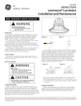
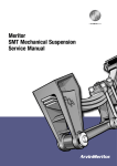
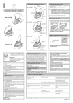
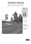
1
Maintenance manual no. MM-0556
Trailer Air Suspension System
MERITOR EUROFLEXTM 9i & 10 Range
Issue: May 2011
Issue 02/2002
Contents
pg. 4
Section 1 - General Information
pg. 38 Section 6 - Axle Alignment (Tracking)
pg. 5
pg. 6
Safety Instructions
Warranty
pg. 39
pg. 39
pg. 39
pg. 8
Section 2 - Introduction
pg. 9
pg. 9
pg. 10
pg. 11
pg. 12
pg. 13
pg. 13
Description
Principle of Operation
Ancilliary Equipment
Important Suspension Parameters
Exploded view & Parts List
ID Plate
Product Updates
pg. 14 Section 3 - Inspection & Maintenance
Procedures
pg. 15
pg. 15
pg. 16
pg. 16
pg. 17
Before entering Service
Inspection
Maintenance
Lubrication
Ride Height Adjustment
pg. 20 Section 4 - Suspension Overhaul
pg. 21
pg. 22
pg. 24
pg. 27
pg. 31
Before you Align Axle
Front Axle
Rear Axle
pg. 42 Section 7 - Axle & Suspension Welding
Recommendations
pg. 43
Axle & Suspension Welding Recommendations
pg. 44 Section 8 - Maintenance Schedules
pg. 45
pg. 46
Maintenance Schedules
Table of Torque Values
pg. 48 Section 9 - Fault Finding & Diagnostics
pg. 49
pg. 49
pg. 49
pg. 49
pg. 50
pg. 50
Braking Problems
Tyre Wear
Excessive Roll
Suspension Related Problems
Axle Lift Problems
Fault Diagnostic Table
Air Spring Removal
Fitting New Air Spring
Shock Absorber Replacement
Pivot Bush Removal
Pivot Bush Replacement
pg. 34 Section 5 - Axle Removal & Replacement
pg. 35
pg. 36
Axle Removal
Axle Replacement
MERITOR EUROFLEXTM 9i & 10 Suspension Range
2
All rights reserved.
No part of this publication may be reproduced in any form or
by any means or granted to any third parties without the
written permission of MERITOR Inc.
MERITOR Inc. reserves the right to publish
revisions at any time for technical or commercial
purposes. Therefore all material contained in this manual is
based on the latest information available at time of publication
approval.
© 2011 Meritor Inc.
Document No. MM-0556
Edition: May 2011
3
MERITOR EUROFLEXTM 9i & 10 Suspension Range
General Information
1
pg. 5
pg. 6
Safety Instructions
Warranty
MERITOR EUROFLEXTM 9i & 10 Suspension Range
4
1 General Information
This manual describes the correct lubrication, service and
installation procedures for the MERITOR EUROFLEXTM 9i & 10
trailer air suspension systems. Information contained in this
publication was in effect at the time the publication was approved
for printing and is subject to change without notice or liability.
The designated trademarks are registered marks of their
respective owners and Meritor Inc. and its affiliates are not
commercially connected, affiliated, or associated with any of the
owners of such marks. The Meritor Inc. products presented herein
are not endorsed or authorized by any of the trademark owners.
You must follow company procedures and understand all
procedures and instructions before you begin to service or repair a
unit. Some procedures require the use of special tools and
lubricants for safe and correct service. Failure to use special tools
when required can cause series personal injury to service
personnel, as well as damage to equipment and components.
MERITOR Inc. uses the following notations to warn the user of
possible safety issues and to provide information that will prevent
damage to equipment and components.
WARNING
A Warning indicates you must follow a procedure exactly.
Otherwise serious Personal injury can occur.
NOTE:
A NOTE indicates an operation, procedure or instruction that
is important for correct service. A NOTE can also supply
Information that can help to make service quicker and easier.
CAUTION
A caution indicates that you must follow a procedure exactly.
Otherwise, damage to equipment or components can occur.
Serious personal injury can also result, in addition to
damaged or malfunctioning equipment or components.
This symbol indicates that a you must tighten
fasteners to a specific torque value.
5
MERITOR EUROFLEXTM 9i & 10 Suspension Range
Safety Instructions
• Observe the manufacturers safety instructions for jacking up
and securing the vehicle
• Only use original Meritor Inc. parts
• Use only the tools recommended
• Observe the following service instructions and notes
• When working on the suspension assembly you must ensure
that it cannot be activated inadvertently
• Never use compressed air to remove dust or for the purpose of
drying. Any type of dust can be injurous to health if inhaled.
• When the servicing has been completed, it is essential that you
road test the vehicle.
Access Information on Meritor Inc's Web
Site
Additional maintenance and service information for Meritor Inc's
commercial vehicle systems component lineup is also available at
www.meritor.com
To access information go to Products & Services Icon; from drop
down menu click on Literature on Demand. The screen will display
an index of publications by type.
1 General Information
MERITOR HVS Suspension Warranty
MERITOR EUROFLEXTM 9i &10 Air Suspension supplied in kits
covered for 24 MONTHS PARTS AND LABOUR
MERITOR EUROFLEXTM 9i & 10 Air Suspension units assembled
with an Axle by Meritor Inc. 36 MONTHS PARTS AND LABOUR.
(MERITOR EUROFLEXTM 9i & 10 Front and Rear Arms welded by
Meritor Inc. are covered for a further 2 years PARTS ONLY)
For full warranty terms and conditions see 'MERITOR Inc. Warranty
Terms and Conditions
Patents and applications of MERITOR HEAVY
VEHICLE SYSTEMS that is specifically relevant to
air suspension systems:
GB Patent No: GB2367111
EU Patent No: EP1315918
US Patent No: US7252298
GB Patent No: GB2396140
GB Patent No: GB2257670
US Patent No: US7360774
Patents applied for:
EPO:
EP030780387
EP050257631
EP060252792
EP050254903
USA:
US10/538816
US11/446,455
US10/916127
US11/875139
China:
CN20038106029
CN061083548
Unless otherwise stated, Aftermarket components are warranted
for 1 year, parts only, mechanical failure only.
Warranty Procedure
Should any MERITOR Inc. equipment fitted to your trailer become
unserviceable within the warranty period, contact the trailer
manufacturer or MERITOR Inc. Service Department who will advise
on the appropriate action.
A comprehensive network of original parts distributors and service
stations operate throughout Europe; this is supported
internationally with agents strategically placed around the world.
Poland: PL20030376676
MERITOR HVS reserves the right to make changes in
specifications shown herein or add improvements at any time
without notice or obligation.
PARTS SHOWN ARE MADE FROM DRAWINGS IN WHICH
COPYRIGHT SUBSISTS. THE MAKING OF COPIES OF ANY OF
THESE PARTS IS PROHIBITED.
ROR, MERITOR, MERITOR Inc. AND INDAIR ARE ALL REGISTERED
TRADE MARKS IN THE UK AND ELSEWHERE
The high quality assurance management systems applied by
MERITOR Inc. are endorsed with the awarding of ISO 9001,
Lloyd's Register Quality Assurance.
© 2011 Meritor Inc.
MERITOR EUROFLEXTM 9i & 10 Suspension Range
6
7
MERITOR EUROFLEXTM 9i & 10 Suspension Range
Introduction
2
pg. 9
pg. 9
pg. 10
pg. 11
pg. 12
pg. 13
pg. 13
Description
Principle of Operation
Ancilliary Equipment
Important Suspension Parameters
Exploded view & Parts List
ID Plate
Product Updates
MERITOR EUROFLEXTM 9i & 10 Suspension Range
8
2 Introduction
Description
Principle of Operation
The MERITOR EUROFLEXTM 9i & 10 range of air suspension
system is based on a semi-trailing arm suspension arrangement.
The trailing arms are mounted onto the axle parallel to one
another and perpendicular to the axle. The front of the trailing
arm consists of a pivot bushing, hanger bracket and alignment
bosses, while the rear of the trailing arm supports the air spring.
(Figs 2.2 and 2.3)
During normal running in a straight line, striking bumps, potholes
etc., superb ride characteristics are obtained due to the airsprings
providing a very low vertical suspension stiffness at the wheel.
This ensures very little shock is transmitted to the
chassis/payload, thus minimising structural damage or problems
with goods.
The axle is attached to the trailing arms via a welding process that
can only be performed by MERITOR Inc. The trailing arms contain
a multi-functional pivot bush at the eye ends, specially designed to
accommodate vertical inputs, but remaining stiff for the fore and
aft inputs. The trailing arms are mounted to hanger brackets,
which are then welded to the chassis.
Ride height is a very important measurement for overall vehicle
height. The ride height of the suspension unit is determined from
the centerline of the axle to the under side of the vehicle chassis.
(Fig 2.1).
Note: Ensure that ride height is set correctly. If ride height is
During cornering manoeuvres, the axle tube acts as an anti-roll
bar and links each trailing arm. The majority of the compliance in
roll comes from the multi-functional pivot bush.
Careful design of the damper characteristics and positioning
ensures a high degree of damping required to gain the best
possible performance from an air suspension.
Modern dynamic analysis methods and testing were used to
determine such characteristics and positions.
Product Compatibilities
The MERITOR EUROFLEXTM 9i Suspension is compatible with the
following brake sizes:
incorrect this may result in damage to suspension components
and affect the trailers performance. Refer to the Trailer
Manufacturers recommendations for ride height setting on tractor
fifth wheel.
Disc Brakes
ELSA 195 (K)
D ELSA 2 (E)
ELSA 225L (J)
D ELSA 2 (E) - 120 OFFSET
ELSA 225L (J) - 120 OFFSET
Features
Drum Brakes
ZMX
QMX
Q+
BMX
ACMX
Shock absorber with integral check strap
9 & 11 Tonne capacity designed for trailers and semi trailers.
Multi-functional bushing with interleaf shims for improved fore/aft
stiffness.
Small diameter air spring for improved packaging.
Nominal ride height of 200 - 500mm with 200mm of total travel
(100mm jounce and 100mm rebound nominal)
9
MERITOR EUROFLEXTM 9i & 10 Suspension Range
For further information visit www.RORCare.com
2 Introduction
Ancillary Equipment
5. ANTI-VACUUM SYSTEM
1. AXLE LIFT FACILITY
Ferry companies require that air suspended trailers are fully
exhausted before trailers are loaded aboard ship.
Consequently there is risk that during loading, the rubber side
walls of the airspring can become trapped between the internal
rubber bump stop and piston and become damaged. Applications
that involve a rapid removal of the load (e.g. HuckePak), could also
cause the airspring sidewalls to become contracted and result in
damage.
These instances can be avoided by using an anti-vacuum system..
A choice of axle lift facilities are available to fit the MERITOR
EUROFLEXTM 9i & 10 suspension, all of which are capable of
being retrofitted.
2. AIRSPRING DUMP FACILITY
MERITOR Inc. recommends that all air suspended trailers without
raise/lower valves are fitted with this facility.
When an air suspended trailer deflates, it can roll forward causing
bending and possible collapse of the landing legs. This is caused
by wheel rotation as the axle travels up. A good solution to this
problem is to fit rocking type landing legs.
6. CHECK STRAPS & QUICK EXHAUST VALVES
All applications that involve a sudden removal of load (e.g. HukePak)
must have a check strap on each axle or quick exhaust valves fitted.
3. RAISE/LOWER FEATURE
If a raise/lower feature is installed on the trailer, the vehicle must
not be driven off with the suspension in the raised or lowered
position. A height limitation valve must me fitted with this feature.
CAUTION: Failure to adhere to this may result in
serious damage to the suspension and may invalidate the
Meritor Inc. warranty.
NOTE: Serious damage can occur to the suspension if the trailer
is driven in the raised/lowered position and doing so may void the
Meritor Inc. warranty.
4. AUTO DROP
MERITOR Inc. recommends the fitment of this system to remove
potential damage to the tyres and running gear, from drivers not
resetting the manual system before moving.
MERITOR EUROFLEXTM 9i & 10 Suspension Range
10
2 Introduction
Fig 2.1
Important Suspension Parameters
A. RIDE HEIGHT
This is the distance from the centre of the axle to the underside
of the chassis.
B. FRAME BRACKET HEIGHT
C. AIRSPRING PEDESTAL HEIGHT
D. PIVOT TO AXLE CENTRE LINE
This is the distance from the pivot centre in the frame bracket
to the centre of the axle tube.*
E. AXLE CENTRE TO AIRSPRING CENTRE LINE
This is the distance from the axle tube centre to the centre of
the airspring pedestal.*
* Both dimension 'D' and 'E' must be measured when the axle
is in the ride height position and dimension 'A' is set.
11
MERITOR EUROFLEXTM 9i & 10 Suspension Range
F. AXLE CENTRE LINE TO PIVOT BUSH CENTRE HEIGHT.
NOTE: Refer to MERITOR Inc. installation drawings CD or contact
MERITOR Inc. Technical Sales Department for allowable options and
recommendations.
2 Introduction
Exploded View - MERITOR EUROFLEXTM 9i & 10 Suspension Assembly
11
10
13
14
15
12
13
9
8
16
14
17
6
5
2
7
5
4
20
3
19
1
18
Fig 2.2
ITEM
DESCRIPTION
QTY
ITEM
DESCRIPTION
QTY
1
AXLE ASSEMBLY
1
11
SHOCK ABSORBER
2
2
PIVOT BUSHING
2
12
SHOCK ABSORBER BOLT - UPPER
2
3
PIVOT BOLT
2
13
WASHER - M24
8
4
ECCENTRIC ALIGNMENT BOSS
2
14
HEX NUT - M24
8
5
WEAR WASHER
4
15
SHOCK ABSORBER BOLT - LOWER
2
6
PIVOT BUSH SLEEVE
2
7
CONCENTRIC ALIGNMENT BOSS
2
16
AIR SPRING PEDESTAL
2
8
WASHER - M24
2
17
HEX NUT - M12
4
9
HEX NUT - M24
2
18
AIR SPRING
2
10
HANGER BRACKET
2
19
RETAINING SCREW M12 - AIR SPRING
4
20
WASHER - M12
4
MERITOR EUROFLEXTM 9i & 10 Suspension Range
12
2 Introduction
Identification Plate Details
The suspension type can be determined by viewing the details in the type box “A” as shown (Fig 2.3)
A
Fig 2.3
Product Updates
There is now an revised hanger bracket design available which has been developed to provide a more durable, lighter product.
NOTE: In the unlikely event that a hanger bracket needs replacing, the new hanger bracket design MUST be replaced in pairs (unless the
trailer is already fitted with the revised design).
Refer to Fig. 2.4 to identify hanger bracket models.
Part Number
Original Hanger Bracket
Part Number
Original Hanger Bracket
(with reinforcement plate fitted)
Fig 2.4
13
MERITOR EUROFLEXTM 9i & 10 Suspension Range
Part Number
Revised Hanger Bracket
Inspection & Maintenance
3
pg. 15
pg. 15
pg. 16
pg. 16
pg. 17
Before entering Service
Inspection
Maintenance
Lubrication
Ride Height Adjustment
MERITOR EUROFLEXTM 9i & 10 Suspension Range
14
3 Inspection & Maintenance
CAUTION
If any welding is done around the suspension and axle running
gear, then suitable precautions should be made to protect the
running gear from weld spatter. Failure to do so may result in
premature failure of running gear components.
Ensure that welding earth clamps or connectors are not connected
to any part of the suspension and axle running gear.
WARNING
To prevent serious eye injury, always wear safe Eye
protection when you perform vehicle maintenance or service.
Before Entering Service
IF THE OPERATOR IS IN ANY DOUBT ABOUT THE SAFETY OF
THE VEHICLE, THEN IT SHOULD NOT BE OPERATED AND
QUALIFIED ADVICE SHOULD BE SOUGHT.
Check the suspension and brake systems operate correctly.
Check the suspension air system for leaks by charging the system
with air and testing all joints and fittings using soapy water.
Inspection
WARNING
Check fastener torque values, tighten loose fasteners and
replace damaged or missing fasteners. Loose, damaged or
missing fasteners can cause loss of vehicle control, death,
serious personal injury and damage to components.
Inspect air suspension components, height control valve and axle
at regular intervals during normal operation and each time the
trailer is serviced.
Before each trip: Visually inspect the suspension system and listen
for any leaks.
Perform the following inspections after the first 1600 km
(1000 miles) of operation and at normal service intervals or
annually thereafter as a minimum.
1.
Check fastener torque values, tighten loose fasteners
and replace damaged or missing fasteners.
2.
Inspect all upper and lower air spring and damper nuts
and bolts for looseness and movement. Tighten any
loose nuts and bolts to the correct torque value as
specified in Section 8. Thereafter, inspect the
suspension components each time the trailer is serviced
or as specified above.
3.
Inspect all height control valve nuts, bolts and linkage
for looseness and movement. Tighten any loose nuts
and bolts to the correct torque value as specified in
Section 8. Thereafter, inspect the suspension
components each time the trailer is serviced or as
specified above
4.
Inspect Pivot bolts for looseness and movement.
Align/Track the axle before tightening any loose nuts
and bolts to the correct torque value as specified in
Section 8. Thereafter, inspect the suspension
components each time the trailer is serviced or as
specified above.
Ensure the suspension ride height is correctly set, by referring to
the Ride Height Adjustment details in Section 2.
If an axle lift system is fitted, operate the lift system to check it
operates correctly and observe the extra lift cylinders attached to
the levelling valve arms to ensure they function.
Carry out a visual inspection of all suspension and brake system
pipe work to ensure no possibility of fouling or rubbing against
each other or other components.
Check the brake system operates correctly.
Check the operation of all optional equipment fitted. If any doubt
or problems arise refer to the appropriate service manual or seek
qualified advice.
15
MERITOR EUROFLEXTM 9i & 10 Suspension Range
3 Inspection & Maintenance
WARNING: Check fastener torque values, tighten
loose fasteners and replace damaged fasteners.
Loose, damaged or missing fasteners can cause loss of
Vehicle control, serious personal injury and Damage to
components.
1.
7.
Inspect shock absorbers for worn bushings, oil leaks
and dents. Check that the mounting holes have not
become enlarged.
8.
Inspect the structure of the suspension including:
Hanger Brackets
Trailing arm
Inspect for, broken or missing fasteners. Repair or
replace as needed. Refer to Section 8 for correct
Torque specifications.
Shock absorber mountings
Axle welds
Brake interference (cam or chamber)
2.
Inspect welds for cracks at the axle, hanger bracket and
suspension trailing arm.
Hanger bracket bracing (where fitted)
Alignment Bosses
Fasteners
3.
Inspect bushings for free play, use a crow bar to check
for looseness or free play. Replace bushings if there are
any signs of excessive vertical movement.
CAUTION: Take care not to damage any of the
suspension components.
WARNING: Verify that people are clear of the trailer
before you inflate or deflate the air springs. The air
suspension has various pinch points that can cause serious
personal injury.
CAUTION: Do not add lubrication or cleaning
4.
Inspect the rubber bellows of the air spring for any cuts
or abrasions. Replace the air spring immediately if it is
cut or damaged in anyway.
CAUTION: The Air Spring surface must be free of
interference or obstructions by items such as tyres,
loose steel and brake chambers etc… Damage to
components can result from abrasion.
solvents to the air system. These additives can
contaminate the air system and damage fittings. Damage to
components will result.
9.
Inspect the height control valve for air leaks and cracked
lever arm housing. If air leaks or cracks are detected,
replace the height control valve.
Lubrication
5.
Check for obstructions or interference to the air spring
surface that can lead to damage to the air spring.
Relocate and secure items, such as air hoses, that can
contact the air spring.
6.
Check for leaks in the air lines, at the air spring bead
plate, piston and mounting studs. Replace air lines,
fittings or air springs that leak. Refer to Section 4 for
replacement details.
The MERITOR EUROFLEXTM 9i & 10 range of suspensions does
not require lubrication, only lubrication is required when installing
replacement pivot bushes.
NOTE: Only use lubricant supplied in the service kit when fitting
new pivot bushes.
MERITOR EUROFLEXTM 9i & 10 Suspension Range
16
3 Inspection & Maintenance
Ride Height Adjustment
WARNING: Overall trailer height must not exceed
recommended limits for territories of application for
the vehicle to clear bridge underpasses during operation.
Serious personal injury and damage to components will
result.
This is an area that is probably most unfamiliar to the trailer
operator and the one that will cause most problems if the
following parameters are not adhered to.
Too high a ride height can cause more roll motion too low means
that there will be loss of axle travel (contacting bump stop) during
arduous use.
8.
The ride height must be set on the axle that has the
levelling valve.
9.
If the trailer is fitted with a lift axle this should be in the
down position.
Once an initial setting of the ride height has been made it should
be checked by measuring from the top of the axle tube to the
underside of the trailer frame, and comparing with the nominal
ride height less 63.5mm (tube radius) (Figs 3.1 & 3.2).
The nominal ride height is specified by the trailer builder and is
shown on the axle or chassis identification plates.
If the ride height is found to require resetting the following
procedure should be used :-
Parameters for setting ride height:
1.
The trailer should be on level ground.
2.
It should preferably be connected to the tractor unit to
be used and in a straight line with the unit, or set at the
correct kingpin height. Refer to chassis identification
plate or contact manufacturer.
3.
All the trailer brakes should be off.
4.
There should be an air supply of at least 6.5 bar.
5.
The trailer should be unladen .
6.
If the trailer has been running it should be given at least
10 minutes to "settle down".
7.
The valve should be set on increasing height as there is
a "dead band" in the actuating stroke of the valve.
17
MERITOR EUROFLEXTM 9i & 10 Suspension Range
Lengthen or shorten the linkage rods which connect the levelling
valve arm to the axle (giving a proportional increase or decrease in
the ride height) by slackening the two screws that pinch the
rubber eye ends onto the drop bar and pulling the bar in or out of
the rubber. If there is insufficient adjustment i.e. the bar is in
danger of coming out of the rubber, then further adjustment can
be gained by slackening the bolts holding the levelling valve to the
bracket and repositioning the valve within the holes. Bending of
the levelling valve actuating arm is not recommended.
If the ride height is found to be above the recommended setting,
the height should first be dropped below the required setting and
then increased back to the nominal ride height, thus avoiding the
"dead band" in the actuating stroke of the valve. This can be done
by shortening the linkage rod and bleeding air from the
suspension by slackening the air pressure connection on top of
the airsprings. This method also applies to situations where the
ride has accidentally been taken above the recommended setting.
NOTE: Some care is needed when checking the ride height as a
false reading may be obtained after tipping a load etc. The
levelling valve emits and exhausts air very slowly, so time should
be allowed for it to react once adjusted.
3 Inspection & Maintenance
The valve emits air slightly faster than it exhausts. This is so that
large volumes of air are not constantly bled off during normal
suspension travel but still allowing a relatively quick reaction to an
increase in load or when the trailer is being brought up to
operating height from flat.
Determining the correct ride height
Measure ride height from the top of the axle to the bottom of the
chassis rail. See diagram (Fig 3.1) and chart (Fig 3.2) for setting
dimensions. This can be found on the axle I.D. plate or contact
MERITOR Inc. Technical Sales Department.
Vehicle
Chassis
Dim
“X”
Dim
“Y”
Ride
Height
Fig 3.1
No.
DIM “Y”
DIM “X”
Ride Height
Model
1
2
3
4
5
6
7
8
9
10
11
12
13
14
15
16
272
297
322
347
372
397
422
447
272
297
322
347
372
397
422
447
136.5
161.5
186.5
211.5
236.5
261.5
286.5
311.5
261.5
286.5
311.5
336.5
361.5
386.5
411.5
436.5
200
225
250
275
300
325
350
375
325
350
375
400
425
450
475
500
Lowmount
Lowmount
Lowmount
Lowmount
Lowmount
Lowmount
Lowmount
Lowmount
Topmount
Topmount
Topmount
Topmount
Topmount
Topmount
Topmount
Topmount
Bush Alignment Damper Pt. No.
L
L
L
L
L
L
L
L
T
T
T
T
T
T
T
T
21228392
21228392
21228392
21228392
21228392
21228392
21228392
21228392
21228930
21228930
21228930
21228930
21228930
21228930
21228930
21228930
Fig 3.2
MERITOR EUROFLEXTM 9i & 10 Suspension Range
18
19
MERITOR EUROFLEXTM 9i & 10 Suspension Range
Suspension Overhaul
4
pg. 21
pg. 22
pg. 24
pg. 27
pg. 31
Air Spring Removal
Fitting New Air Spring
Shock Absorber Replacement
Pivot Bush Removal
Pivot Bush Replacement
MERITOR EUROFLEXTM 9i & 10 Suspension Range
20
4 Suspension Overhaul
MERITOR EUROFLEXTM 9i & 10 Air Spring Range
WARNING
Park the un-laden vehicle on a flat surface and block the
wheels to prevent the vehicle from moving. Support the
vehicle with safety stands. Do not work under a vehicle
supported only by jacks. Jacks can slip or fall over. Serious
personal injury can result.
Air Spring Replacement
Removal
1 Expel all air from the system (Fig 4.1).
Fig 4.1
Fig 4.2
Fig 4.3
2. Remove the air inlet pipe from the push to connect fitting (Fig
4.2).
3. Using a 19mm spanner remove the M12 nuts from the top of
the air spring (Figure 4.3) and the two M12 bolts and washers
securing the airspring piston to the trailing arm (Fig 4.4).
4. Remove the complete airspring by compressing it slightly if
required.
Fig 4.4
21
MERITOR EUROFLEXTM 9i & 10 Suspension Range
4 Suspension Overhaul
5. Remove the air fitting (Fig 4.5).
3. Align and locate the air inlet and mounting stud respectively in
the slot and hole on the pedestal (Fig 4.7).
PostScript Picture
Bw 1820
Fig 4.5
Fig 4.7
Fitting a New Air Spring
1. Fit the air fitting (Fig 4.6).
4. Align and locate the lower mounting bolt holes with
the relevant holes in the trailing arm platform (Fig 4.8).
Fit new retaining bolts and washer and tighten to a torque of
70Nm.
PostScript Picture
Bw 1820
Fig 4.6
2. Compress the new air spring and slide into position between
the trailing arm platform and the sir spring pedestal.
Fig 4.8
MERITOR EUROFLEXTM 9i & 10 Suspension Range
22
4 Suspension Overhaul
5. Fit new nuts to the upper mounting studs and tighten to a
torque of 41Nm (Fig 4.9)
7. Pressurise the air system (Fig 4.11).
Fig 4.11
Fig 4.9
6. Connect the airline (Fig 4.10).
CAUTION
The air spring and connecting pipes must be free from
interference or obstruction by tyres, metal components etc.
Damage to components through abrasion will result in
premature failure.
8. Check that tyres, metal components etc. do not interfere with
the air spring, particularly the rubber components.
9. Check all disturbed connections for air leaks.
10. Raise the trailer and remove the safety stands.
11. Verify that the ride height of the trailer is correct. Refer to the
trailer OEM's specification for the correct ride height. Adjust
accordingly following the procedure detailed in the Section 3 Ride
Height Adjustment.
Fig 4.10
23
MERITOR EUROFLEXTM 9i & 10 Suspension Range
4 Suspension Overhaul
WARNING
Shock Absorber Replacement
Verify that people are clear of the trailer before you inflate or
deflate the air springs. The air suspension has various pinch
points that can cause serious personal injury.
Meritor Inc. shock absorbers incorporate an integral check strap
feature. However, where the trailer may be subject to a sudden
removal of load e.g. HukePak, axle check straps must be fitted.
Park the un-laden vehicle on a flat surface and block the wheels
to prevent the vehicle from moving. Support the vehicle with safety
stands. Do not work under a vehicle supported only by jacks.
Jacks can slip or fall over. Serious personal injury can result.
CAUTION: Failure to adhere to this may result in
serious damage to the suspension and may
invalidate the Meritor Inc. warranty.
MERITOR EUROFLEX TM 9i & 10 Shock Absorber
Check Shock bushings for looseness and wear. Replace worn or
damaged bushes or shock absorbers. Worn or damaged shock
absorbers can lead to reduced ride and handling performance of
the trailer.
NOTE: Ensure that when replacing Shock absorbers, the correct
size of Shock absorber is fitted to Lowmount or Topmount
suspension installations.
Lowmount Shock Absorber - 21228392
Topmount Shock Absorber - 21228930
NOTE: The protective shroud A on the shock absorber must not
be removed (Fig 4.12).
Shock absorbers must be fitted in the correct orientation. Current
shock absorbers incorporate an adhesive label with the word
“TOP” to indicate the correct orientation (Fig 4.12).
NOTE: Early level shock absorbers have an adhesive label
attached indicating the bottom of the shock absorber.
CAUTION: If shock absorbers are fitted in the
wrong orientaion there will be a loss of any
suspension damping, causing severe damage to the vehicle.
A
Fig 4.12
MERITOR EUROFLEXTM 9i & 10 Suspension Range
24
4 Suspension Overhaul
Removal
2. Withdraw the lower mounting bolt (Fig 4.14).
Identify the specific shock absorber that is damaged or leaking.
NOTE: On certain applications it may be necessary to remove
1. With the trailer in its normal ride height (un-laden) using a 36
mm socket and ring spanner, remove the nuts and washers from
the upper and lower damper bolts (Fig 4.13).
the brake chamber to provide clearance for lower shock absorber
mounting bolt removal. For brake chamber removal instructions
refer to the appropriate MeritorInc. brake service manual.
Fig 4.14
Fig 4.13
3. Remove the damper from the upper mounting bolt (Fig. 4.15).
NOTE: It is not possible to remove the upper mounting bolt with
the road wheels fitted to the trailer.
Fig 4.15
25
MERITOR EUROFLEXTM 9i & 10 Suspension Range
4 Suspension Overhaul
Replacement
1. Locate the top eye of the damper on to the upper mounting
bolt. Fit a new nut and washer (Fig 4.16).
NOTE: Ensure suspension is at the ride height setting before fully
tightening to torque.
Pivot Bush
CAUTION: Ensure the pips on the replacement
Pivot Bush are in line with the correct alignment
boss, either T (TOP mount) or L (LOW mount) and the steel
plates ‘A’ are aligned front and rear, not top and bottom, as
shown in Fig 4.18.
Bush Alignment - Front Arm Orientation
Top Mount
A
Fig 4.16
2. Rotate the damper and slowly pull it to extend its length until
the lower eye aligns with the mounting hole in the trailing arm. Fit
the lower mounting bolt, flat washer and new nut. Ensure the bolt
head is inboard.
A
“T” Marked
Boss
3. Using a 36mm socket and ring spanner torque the
two nuts to 500 Nm (Fig 4.17).
Low Mount
A
A
“L” Marked
Boss
Fig 4.17
Fig 4.18
MERITOR EUROFLEXTM 9i & 10 Suspension Range
26
4 Suspension Overhaul
A - Nut
B - Cup & Bearing
C - FBT (Front Bush Tool)
D - Funnel
E - Inner Sleeve
F - RBT (Rear Bush Tool)
G - Threaded Bar
H - Washer
I - Trailing Arm
Fig 4.19
WARNING
Check pivot bushings for looseness and wear. Replace worn
or damaged pivot bushings. Worn bushings can loosen and
cause the trailer to wander during operation. Serious injury
and damage to components can result.
NOTE: Check the position and orientation of the original bush
before removing (Fig 4.18). This will provide a guideline when
fitting a new bush.
Pivot Bush Removal
1. Lower the landing gear.
Verify that people are clear of the trailer before you inflate or
deflate the air springs. The air suspension has various pinch points
that can cause serious personal injury.
Park the un-laden vehicle on a flat surface and block the wheels
to prevent the vehicle from moving. Support the vehicle with safety
stands. Do not work under a vehicle supported only by jacks.
Jacks can slip or fall over. Serious personal injury can result.
NOTE: This following procedure requires the assistance of
another person.
Before removal and fitment of pivot bushes;
A genuine MERITOR CVA pivot bush replacement kit is required.
A pivot bush removal and insertion tool (Part No. MST 3420) will
be required Fig 4.19).
27
MERITOR EUROFLEXTM 9i & 10 Suspension Range
2. Support the REAR of the trailer frame.
3. Set the parking brake.
4. Exhaust air pressure from the suspension air springs.
5. Support the axle and remove the wheel/(s) to access the pivot
bolts.
NOTE: Although It is not necessary to remove the road wheels
when replacing the pivot bushes on SINGLE wheel axle
configurations, the procedure may be easier with the wheels
removed.
6. Remove the bottom shock absorber bolts from both hanger
brackets. This will allow the trailing arm to articulate down when
the pivot bolts are removed.
4 Suspension Overhaul
7. Remove the pivot bolts and alignment bosses from the hanger
bracket (Figs 4.20 & 4.21).
Fig 4.20
WARNING
Ensure that the axle support is secure during this operation
as the arcuate motion may cause the axle to move
backwards (Fig 4.22).
Fig 4.22
Fig 4.21
8. Carefully rotate the trailing arm until clear of the hanger
bracket (Fig 4.23) and (Fig 4.24). DO NOT lever off the brake
chamber as shown (Fig 4.25).
Fig 4.23
MERITOR EUROFLEXTM 9i & 10 Suspension Range
28
4 Suspension Overhaul
X
Fig 4.24
Fig 4.25
9. Remove the wear washers and the steel inner sleeves from the
pivot bushes (Figs 4.26 & 4.27).
Fig 4.27
Fig 4.26
10. Using the MERITOR CVA service tool MST 3420 replace the
pivot bushes as described in the following paragraphs .
29
MERITOR EUROFLEXTM 9i & 10 Suspension Range
11. Insert inner sleeve “E” from the service tool into the pivot bush
central tube.
4 Suspension Overhaul
12. Press the Front Bush Tool (FBT) “C” against the pivot bush and
insert the threaded bar “G”. Fit washer “H” and nut “A” to draw
bar and secure to FBT “C” (Fig 4.28).
Fig 4.28
13. Push funnel “D” onto the trailing arm outer tube opposite the
FBT “C” (Recess facing towards pivot bush) (Fig 4.29).
Fig 4.29
14. Attach the Rear Bush Tool (RBT) “ F” to the funnel “D” and
secure in place with the bearing cups, bearing race “B” and nut
“A” (Fig 4.30)
Fig 4.30
15. Apply turning moment to the nut “A” at the bearing end,
continue turning the nut until the pivot bush is drawn completely
into the funnel “D” (Fig 4.31).
Fig 4.31
MERITOR EUROFLEXTM 9i & 10 Suspension Range
30
4 Suspension Overhaul
16. Dismantle the tooling and remove the pivot bush from the
funnel “D” (Fig 4.32).
Pivot Bush Replacement
1. Apply P-80 gel solution around the pivot bush (Fig 4.33), funnel
“D” (Fig 4.34) and trailing arm outer tube (Fig 4.35).
Fig 4.32
17. Remove any debris that may be left from the trailing arm outer
tube.
Fig 4.33
Fig 4.34
31
MERITOR EUROFLEXTM 9i & 10 Suspension Range
4 Suspension Overhaul
3. Fit bush tool to trailing arm as shown (Fig 4.37).
Fig 4.35
2. Insert the replacement pivot bush into the funnel “D” and align
the pips on the pivot bush with the marked line on the funnel (Fig
4.36)
Fig 4.37
4. Insert inner sleeve “E” into the pivot bush central tube.
5. Press the Rear Bush Tool (RBT) “F” against the trailing arm
outer tube and insert the threaded bar “G”. Fit washer “H” and nut
“A” to draw bar and secure to RBT “F”.
6. Push funnel “D” onto the trailing arm outer tube opposite the
RBT “F” (Recess facing towards outer tube). Attach the FBT “C” to
the funnel “D” and secure in place with the bearing cups, bearing
race “B” and nut “A”.
7. Rotate the funnel “D” so that the mark is aligned to the mark
on the trailing arm (Fig 4.38)
Fig 4.36
8. Apply turning moment to the nut “A” at the bearing “B” end,
continue turning the nut until the pivot bush is drawn completely
into the trailing arm outer tube. The turning action will lock out
when the pivot bush mates up with the RBT ”F”.
9. Back off the nut and dismantle the pivot bush tooling. Check
for any damage to the membrane of the pivot bush.
MERITOR EUROFLEXTM 9i & 10 Suspension Range
32
4 Suspension Overhaul
11. Refit the trailing arm to the hanger bracket (Fig 4.40) and
insert new pivot bolts.
Fig 4.38
10. Insert steel inner sleeve "X" into the pivot bush central tube.
Fit the replacement wear washers "Y" to either side of the pivot
bush (Fig 4.39).
Fig 4.40
Do not torque the pivot nuts to final torque until the axle is aligned
and the trailer is at the ride height with the wheels on. See Axle
Alignment - Section 6 and refer to the Ride Height Adjustment
details - Section 3.
12. Refit the shock absorber. Do not torque the Shock absorber
nuts to final torque until the axle is aligned and the trailer is at the
ride height with the wheels on. See Axle Alignment Section 6
and refer to the Ride Height Adjustment details - Section 3.
Y
13. Refit the wheel (s), where applicable, pressurise the air springs
and set ride height.
X
Fig 4.39
33
14 Torque all nuts and bolts to final tightening torque.
Refer to Section 8 for torque specification table
MERITOR EUROFLEXTM 9i & 10 Suspension Range
Axle Removal & Replacement
5
pg. 35
pg. 36
Axle Removal
Axle Replacement
MERITOR EUROFLEXTM 9i & 10 Suspension Range
34
5 Axle Removal & Replacement
NOTE: The MERITOR EUROFLEXTM 9i & 10 suspension is an
integrated axle and suspension module. The suspension cannot be
removed from the axle. Any attempt to do so will seriously damage
the axle and suspension and will invalidate the Meritor Inc.
warranty.
5. Jack up the trailer and support it under the chassis to take the
weight of the axle to be removed.
6. Support the axle to be removed on stands such that a pump
trolley or similar device can be slid between them lower the axle
once it is unbolted from the suspension.
Removal
7. Remove the wheels from the axle.
1. Ensure no air is left in the system.
2. If spring brakes are fitted they should be released and
constrained using a caging tool.
8. Using a 36 mm spanner and socket, remove the nut and
washer from the lower damper bolt and withdraw the bolt. Slacken
the top damper bolt nut and pivot the damper upwards to clear
the axle and secure it to the chassis.
3a. Drum Brake Trailers - Remove the split pins and clevis pins
securing the brake chambers to the slack adjuster levers.
9. If required, remove the airspring as detailed in Section 3.
3b. Disc Brake Trailers - Remove the brake pipes, leaving the
chamber attached to the calliper.
For single axle trailers and rear axles of tandems and tri-axles
proceed as follows;
4. If the axle is used to locate the bottom arm, with the
suspension height control valve, remove the eye coupling on the
levelling valve arm from the pin on the axle (Figure 5.1).
10. Using a 36 mm spanner and socket, slacken the two main
pivot bolt nuts just enough to allow the arms to easily pivot.
11. Slide trolley jacks as required under the axle, jack them up to
take the weight of the stands. Remove the stand and lower the
jacks. Pull the axle clear backwards and clear of the trailer.
For the front axle of a tandem and the centre or the front axle on a
triaxles trailer proceed as follows;
12. Using a 36 mm spanner and socket, remove the two main
pivot nuts and washers and remove the bolts ensure the arms are
supported to prevent them dropping.
13. Slide trolley jacks as required under the axle and take the axle
weight. Remove the axle stands and slide the axle out sideways.
Fig 5.1
35
MERITOR EUROFLEXTM 9i & 10 Suspension Range
5 Axle Removal & Replacement
Replacement
If the original axle and suspension unit is not refitted, the
replacement must be supplied and approved by MERITOR Inc.
8. Drum Brake Trailers-refit the brake chambers on the air
chamber brackets and secure using the original nuts if
undamaged, ideally new nuts and washers should be used, ensure
nuts and washers are clean.
If in doubt contact the MERITOR Inc. Technical Sales Department
for detailed recommendations.
9. Disc Brake Trailers-reconnect the brake pipes.
1. Lift axle onto trolley jacks and rotate to ensure it's correctly
oriented.
2. For single axle trailers and rear axles of tandems and triaxles
slide the axle and suspension unit sideways into position, and
place the arms eye ends in the position in the frame brackets.
10. Refit the clevis and split pins in the slack adjuster levers and
remove the spring cages if spring brakes are fitted. Check the
brake adjustment as detailed in the MERITOR HVS axle service
manual.
11. Refit the road wheels and lower trailer chassis and axle off
their support stands.
3. Align the holes in the arm bushes - ENSURE NO GREASE IS
ON THE THREADS. Fit the bolts, washers,wear washers, bush
inner sleeves and nuts and tighten such that the arms can pivot
easily.
Continue for all models as follows:
4. Lower/raise the axle and trailing arm until the hole in the lower
damper bush is aligned with the location hole in the arm, if the old
bolts are being re-used ,ensure they are clean (especially the
threads) and undamaged - ENSURE NO GREASE IS ON
THREADS.
Re-fit the bolts.
5. Fit new nuts and washers, do not tighten at this stage.
6. If required, re-fit the air spring as detailed in Section 3.
7. Lower/raise the axle and arms until the axle is in the ride
height position (see section 1). IT IS VERY IMPORTANT THAT THE
DAMPER AND PIVOT BOLTS ARE FULLY TIGHTEND WHEN AXLE
IS IN THE RIDE HIEGHT POSITION. Torque up the top and bottom
damper bolts using a 36mm spanner and socket and the pivot
bolts. Refer to torque tables - Section 8.
MERITOR EUROFLEXTM 9i & 10 Suspension Range
36
37
MERITOR EUROFLEXTM 9i & 10 Suspension Range
Axle Alignment (Tracking)
6
pg. 39
pg. 39
pg. 39
Before you Align Axle
Front Axle
Rear Axle
MERITOR EUROFLEXTM 9i & 10 Suspension Range
38
6 Axle Alignment
This section provides details of how to re-align suspensions if their
settings are changed due to other work.
All MERITOR EUROFLEXTM 9i & 10 models are available with the
patented pivot eye tracking facility. This is re-usable and does not
require welding, and offers +/- 7 mm of fore and aft movement.
3. Using a 36 mm spanner and suitable wrench, loosen the pivot
bolts on both sides. Place 36 mm spanner on an outboard boss
(eccentric boss) (Fig 6.1), and rotate in desired direction to give an
equal measurement on either of the axle to the kingpin.
It is recommended that tracking is performed before painting, and
that no debris is left in the clamped faces of the joint.
Before you align the Axle
1. The trailer must be on a level surface and un-laden.
2. Adjust the trailer landing gear: The height of the king pin should
be the same as when the trailer is connected.
3. Support the chassis on suitable axle stands
4. Expel all air from the system.
Fig 6.1
5. Remove the road wheels.
NOTE: To obtain correct alignment, the dimensions DR and DL
Front Axle
1. Verify that the suspension is at the correct ride height. Refer to
Ride Height Adjustment - Section 3
2. Measure from the king pin to each end of the first axle
(measurement DR and DL. To obtain correct alignment, settings
(Figs 6.2 & 6.3).
must be within +/- 3mm at both ends of the axle (Figs 6.2 & 6.3)
.
Repeat the procedure on the other pivot bolt if required.
When the desired measurements have been achieved,
tighten pivot bolts to 800 Nm.
Rear Axle
1. Check the dimension from the centerline of the front axle to the
centerline of the rear axle (measurements AR and AL).
NOTE: Rotate the hub backwards and forwards to ensure that the
If Adjustment is required: Proceed to step 3 below. If Adjustment is
not required: Proceed to 'Rear Axle' in this section.
2. To obtain correct alignment, the dimensions must be within +/3mm at both ends of the axle. (Figs 6.2 and 6.3). If Adjustment
is required: Proceed to step 3 below. If Adjustment is not required:
Proceed to step 4.
NOTE: Before you align an axle, ensure the pivot bolt is free to
NOTE: Before you align an axle, ensure the pivot bolt is free to
move in the adjustment slot.
move in the adjustment slot.
measurement is the maximum possible.
39
MERITOR EUROFLEXTM 9i & 10 Suspension Range
6 Axle Alignment
3. Using a 36 mm spanner and suitable wrench, loosen the pivot
bolts on both sides. Place 36 mm spanner on an outboard boss
(eccentric boss) (Fig 6.1), and rotate in desired direction to give an
equal measurement on either of the axle to the kingpin.
NOTE: Align the axle so that measurement AR equals
measurement AL within +/- 3 mm. (Figs 6.2 and 6.3)
Repeat the procedure on the other pivot bolt if required.
4. When the axle is aligned correctly, tighten the pivot
bolts to 800 Nm.
5. Refit the road wheels.
6. Charge the system with air.
7. Apply the parking brake.
8. Remove the chassis stands
9. Reinflate the suspension
AR = AL +/- 3mm
LR = LL +/- 2mm
DR = DL +/- 1.5mm
o
o
0 = 90 +/- 1/6
Fig 6.2
MERITOR EUROFLEXTM 9i & 10 Suspension Range
40
6 Axle Alignment
AR = AL +/- 3mm
BR = BL +/- 3mm
LR = LL +/- 2mm
DR = DL +/- 1.5mm
o
o
0 = 90 +/- 1/6
Fig 6.3
41
MERITOR EUROFLEXTM 9i & 10 Suspension Range
Axle & Suspension Welding Recommendations
7
pg. 43
Axle & Suspension Welding Recommendations
MERITOR EUROFLEXTM 9i & 10 Suspension Range
42
7 Axle & Suspension Welding Recommendations
WARNING: To prevent serious eye injury, always
wear always wear safe eye protection when you
perform vehicle maintenance or service.
Incorrect weld placement will void MERITOR Inc's warranty and
can reduce the fatigue life of the trailer axle beam and suspension
components. Serious personal injury can result.
The suspension and axle must be protected from heat and weld
spatter to avoid damage and any plastic or rubber components
must be properly covered. All parts must be dry and free from oil
and dirt prior to welding. Ensure that the suspension is properly
earthed to avoid arcing.
WARNING: Incorrect weld placement, or weld
spatter, can result in reduced fatigue life of the
suspension system, serious personal injury and damage to
components.
For further information refer to the ROR Care website at
www.RORCare.com
Refer to the MERITOR EUROFLEXTM 9i & 10 Suspension General
Assembly Drawings for further details.
43
MERITOR EUROFLEXTM 9i & 10 Suspension Range
Maintenance Schedules
8
pg. 45
pg. 46
Maintenance Schedules
Table of Torque Values
MERITOR EUROFLEXTM 9i & 10 Suspension Range
44
8 Maintenance Schedules
After First 1000 KM
Check all fastener torques and tighten where required according
to the values in the table in this section.
Examine all valves and air hose joints for leaks or signs of pipe
work rubbing against the chassis or suspension components.
Check the suspension ride height as explained in Section 3.
Inspect the dampers for evidence of oil leaks.
If an axle lift is fitted, check that it is functioning correctly.
Check the operation of all optional equipment and test for air leaks
on air system equipment. Individual service manuals should be
referred to if required.
If an axle lift assembly is fitted ensure it is operating correctly.
Check the extra air springs (if fitted) are operating as the axle is
being raised. For detailed information refer to the Meritor Inc. Lift
Axle manual
Check arms and welds for cracks in all inspection intervals stated.
Every 100,000 KM
Check the dampers for oil leaks along their body. Lever between
the damper eye ends (top and bottom) and close bracketry to
ensure no excessive lateral movement exists indicating bush
failure or loose bolts.
Check arms and welds for cracks in all inspection intervals stated.
Check the airsprings for air leaks and signs of damage especially
to the rubber bellows. Details of replacing them can be found in
Section 4.
After First 10000 KM & Subsequent 10,000 KM
Intervals
Uncouple the levelling valve arm/axle rubber joint and raise and
lower the arm to check that the valve is passing air in and out of
the suspension system.
Inspect the dampers for evidence of oil leaks and inspect the
damper bushes for signs of rubber extrusion or damage.
Check the airsprings for signs of leakage and examine the rubber
bellows for signs of damage from road debris or internal bump
stop failure.
Check all pipe joints for signs of leakage and ensure that no
valves are fouled with road dirt such that their operation may be
impaired. This is especially relevant to the levelling valve. This is
particularly important if the trailer has been operated in a harsh
environment e.g. coal, dust, quarries etc.
If an axle lift is fitted, check it is operating correctly.
Check the operation of all optional equipment and test for air leaks
on air system equipment. Individual service manuals should be
referred to if required.
Examine tyres for uneven wear. If there is any present check the
pivot bushes for damage and re-check the axle alignment as
detailed in Section 6.
If damage is found then the trailing arms should be removed as
detailed in Section 4 and replacement of the bush and possibly
the wear plates is advised. Failure to do so may result in tyre wear
or structural damage.
Check all fastener torques and tighten where required according
to the values in the table in this section.
45
MERITOR EUROFLEXTM 9i & 10 Suspension Range
Check the pressure protection valve by draining the brake and
suspension air tanks and couple up an air pressure gauge to each
tank. With an air supply of 6.5 bar, recharge the tanks. The brake
tank pressure should reach 5.5 bar minimum before the
suspension tank begins to charge.
Clean under the suspension inside the hanger brackets and
around the trailing arm pivots. Check between the wear plates on
the inside faces of the hanger brackets and the trailing arms for
signs of excessive wear or damage to the rubber pivot bushes.
All torques must be within ±5% of stated values.
Check arms and welds for cracks in all inspection intervals stated.
WARNING
Check fastener torque values, tighten loose
fasteners and replace damaged fasteners. Loose, damaged
or missing fasteners can cause loss of vehicle control, death,
serious personal injury and damage to components.
8 Maintenance Schedules
Table of Torques Fasteners
Fastener Description
Torque (Nm) +/- 5%
Pivot Nut
800 *
Shock Absorber Nut (Top & Bottom)
500 *
Upper Air spring nut (M12)
41
Lower Air spring Screw (M12)
70
NOTE: * Do not torque the Pivot Nut or Shock Absorber nuts to
final torque until the axle is aligned and the trailer is at the ride
height with the wheels on. Refer to Axle Alignment - Section 6
(Figs 6.2 & 6.3) and Ride Height Adjustment - Section 3
MERITOR EUROFLEXTM 9i & 10 Suspension Range
46
47
MERITOR EUROFLEXTM 9i & 10 Suspension Range
Fault Finding & Diagnostics
9
pg. 49
pg. 49
pg. 49
pg. 49
pg. 50
pg. 50
Braking Problems
Tyre Wear
Excessive Roll
Suspension Related Problems
Axle Lift Problems
Fault Diagnostic Table
MERITOR EUROFLEXTM 9i & 10 Suspension Range
48
9 Fault Finding & Diagnostics
This section is intended to give a guide to the trailer operator to
enable him to assess problems. The range of problems and
suggested causes and cures are by no means complete but are
intended to provide a solution to the most commonly encountered
difficulties.
NOTE: IF THE OPERATOR IS IN DOUBT ABOUT THE SAFETY OF
THE VEHICLE HE SHOULD NOT OPERATE IT, AND SHOULD
IMMEDIATELY SEEK QUALIFIED ADVICE FROM MERITOR Inc.
How to use this section.
The faults are listed under five main headings, namely
1. BRAKING PROBLEMS
2. TYRE WEAR
3. EXCESSIVE ROLL
4. SUSPENSION AIR RELATED PROBLEMS
5. AXLE LIFT RELATED PROBLEMS
Listed under each of these headings are the likely specific
problems, each followed by a check procedure which should
highlight the cause of the problem. If the problem cannot be
solved after working through the relevant check list, then further
information should be obtained from MERITOR Inc.
Braking Problems
If brakes are not functioning correctly:
• Check that there is at least 6.5 bar at coupling head, and the
correct ratio of air is delivered to the brake chamber.
• Check slack adjusters are correctly adjusted
• Ensure all brake system valves are functioning correctly
Tyre Wear
If tyre wear is excessive:
• Check axle alignment is correct
• Check wheels are parallel (i.e. zero camber and toe in/out)
• Inspect the trailing arm pivot bushes for damage, and replace if
necessary
• Check shock absorber for oil leaks
• Inspect shock absorber bushes for damage
• Ensure ride height is set correctly
• Check application, operation and route.
• Ensure no axle is lifted when trailer is fully loaded.
Excessive Roll
If trailer is rolling excessively:
• Check pivot bolt torque is correct
• Check pivot bush condition.
• Check axle and suspension trailing arms for cracks.
Is centre of gravity excessive ?
• Ensure ride height is set correctly
• If vehicle is load sensed, check that a shuttle valve is fitted to
prevent cross coupling. Fit if necessary
Suspension Air Related Problems
If suspension will not inflate:
• Check that the levelling valve is connected to the axle
• Ensure the brake air reservoir pressure is more than 6.5 bar
• Ensure the suspension air reservoir pressure is at least 6.5 bar
IF PROBLEM PERSISTS SEE MERITOR Inc. AXLE AND BRAKE
SERVICE MANUALS FOR FULL BRAKE SERVICE PROCEDURE.
OR SEE WWW.RORCare.COM
• Check the setting of the pressure protection valve and clean the
air filter
• Check the axle load is not greater than the available pressure
• Check all pipework and fittings for leaks using soapy water
• Check the airsprings for leaks using soapy water
49
MERITOR EUROFLEXTM 9i & 10 Suspension Range
9 Fault Finding & Diagnostics
• Check levelling valve for leakage at the exhaust port, and if
necessary replace valve If suspension is deflating:
• Check all pipework and fittings for leaks using soapy water
• Check the airsprings for leaks using soapy water
• Check levelling valve for leakage at the exhaust port, and if
necessary replace the valve
Axle Lift Related Problems
If lift will not operate:
• Work through check procedure for main suspension airsprings
not inflating.
• Check that the lift valve is correctly installed and piped. Replace
valve if faulty.
For detailed information refer to the Meritor Inc. Lift Axle manual
Fault Diagnostic Table
Condition
All air springs flat
Air springs fully raised but do not
exhaust
Vehicle body incorrect ride height during
operation
Possible Cause
Recommended Action
1
Insufficient air pressure to
suspension air springs.
Build air pressure to 6.5 Bar, or
more. Check compressor for
correct function. Check all air lines
and fittings for
leaks.
2
Defective pressure protection
valve.
Check and replace valve if
necessary.
3
Height control valve supply or
delivery fitting clogged.
Inspect height control valve supply
& delivery fittings for restrictions.
4
Air leak in system
Inspect entire system for leaks.
Repair orreplace as necessary.
5
Suspension overloaded.
Review load to suspension rated
capacity
1
Height control valve delivery port or
exhaust port plugged.
Inspect port for restrictions. Repair
or replace as necessary.
2
Height control linkage broken
Replace linkage.
1
Height control valve not adjusted
properly
Inspect and adjust as necessary.
2
Height control lever bent or
broken
Straighten or replace lever.
MERITOR EUROFLEXTM 9i & 10 Suspension Range
50
9 Fault Finding & Diagnostics
Condition
Possible Cause
Recommended Action
Vehicle body incorrect ride height during
operation
3
Insufficient air pressure to the Check air compressor and pressure
suspension system.
protection valve for proper operation.
Inspect system for leaks. Repair and
replace as necessary.
Main air pressure drops to 6.5 Bar
1
Ruptured air spring
Inspect air springs and replace as
necessary.
2
Leaking air lines
Insperct air lines and repair or replace
as necessary.
Hard Ride
1
Improper ride height or air
springs flat
Check and adjust ride height. See first
condition
Suspension ride height not maintained
during operation
1
Clogged air filters
Inspect and clean or replace as
necessary.
2
Moisture in air tank
Drain air tank and evacute air system
of moisture.
3
Clogged filter screens in
height control valve
Inspect and clean or replace as
necessary.
4
Damaged linkage or incorrect Replace, repair or adjust as necessary.
valve mounting
Incorrect tyre clearance in full bounce
1
Incorrect tyre size
Replace tires with the recommended
tyre size.
Trailer not pulling straight (dog-walk)
1
Trailer axles out of alignment
Realign axles
2
Loose alignment bosses or
pivot bolt
Align axles and tighten pivot bolts to
the correct torque.
Trailer wandering or unusual rattling
1
Worn bushings
Inspect bushings and replace as
needed
Broken Shock Absorbers
1
Trailer fitted with manual
raise/lower valve. Driver
forgets to set to ride height
Fit auto raise/lower device.
Driver education.
2
Auto reset fitted, check
Check operation
function of Colas/EBS tractor is
compatible
3
Is trailer towed on sit with
Dock spotter etc.
Check operation
4
Incorrect King pin height
Set Kingpin height to recommended
values from trailer plate details or
contact manufacturer
Air spring bump stop broken
1
Trailer driven with no air in the Driver education
suspension
Damage to lifter in red emergency coupling at
headboard of trailer
1
Dirt in air system.
2
General wear and tear
51
MERITOR EUROFLEXTM 9i & 10 Suspension Range
Check operation. Replace worn lifter in
coupling
For further information contact
Meritor Commercial
Vehicle Aftermarket AG
Neugutstrasse 89
8600 Dübendorf
Switzerland
Tel +41 44 824 8200
Meritor HVS Ltd
Grange Road, Cwmbran
NP44 3XU Torfaen - UK
Tel +44 (0)1633 834 040
www.meritor.com
www.RORCare.com
© 2011 Meritor Inc.
Meritor Automotive
All rights Reserved
Publication: MM-0556
Descriptions and specifications were in effect at the
time of this publication and are subject to change
without notice or liability. Meritor reserve the right to
make design improvements, change or discontinue
parts at any time