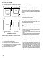
1
SERVICING
6. Reconnect wires to the control and place in a heating
cycle.
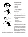
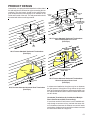
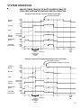
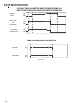
7. Begin to restrict the flue outlet until the pressure control
trips - cycling OFF the burner. Also a blocked drain test
will need to be performed until the coil cover pressure
control trips - cycling OFF the burner. The trip points
should be as shown in the Pressure Switch Trip Points
and Usage Charts in furnace Technical Manual.
8. If not as listed, replace control.
9. After completing check and/or repair of pressure switch,
reinstall burner compartment door.
10. Turn on electrical power and verify proper unit operation.
The pressure readings listed in the Pressure Switch Trip
Points and Usage Charts in furnace Technical Manual must
be adhered to for proper operation.
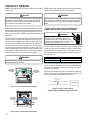
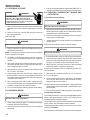
S-9 CHECKING AIR CIRCULATOR BLOWER MOTOR OR INDUCED DRAFT BLOWER MOTOR
WARNING
HIGH VOLTAGE
DISCONNECT ALL POWER BEFORE SERVICING OR
INSTALLING THIS UNIT. MULTIPLE POWER SOURCES MAY
BE PRESENT. FAILURE TO DO SO MAY CAUSE PROPERTY
DAMAGE, PERSONAL INJURY OR DEATH.
1. Remove blower compartment door to gain access to the
circulator blower motor and induced draft blower motor
wire leads connected at integrated ignition control.
2. Disconnect the motor wire leads from its connection point
at integrated ignition control module and capacitor if applicable.
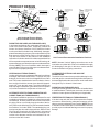
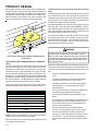
3. Using an ohmmeter, test for continuity between each of
the motor leads.
4. Touch one probe of the ohmmeter to the motor frame
(ground) and the other probe in turn to each lead.
If the windings do not test continuous or a reading is obtained to ground, replace the motor.
5. After completing check and/or replacement of circulator
blower motor or induced draft blower motor, reinstall
blower compartment door.
6. Turn on electrical power and verify proper unit operation.
S-9A CHECKING VARIABLE SPEED AIR CIRCULATOR BLOWER MOTOR
The 80% and 90% Two-Stage Variable Speed furnaces incorporate the GE© ICM or variable speed blower motors for
greater efficiency. ECM/ICM motors vary the motor RPMs
to provide a set volume of air over a wide range of conditions.
These motors use an electronic control module attached to
the motor to control motor operation. Some unique features
of these motors are:
144
1. Constant Airflow. These motors will maintain constant
airflow in excess of .80 static. In other words, as the
static increases so does the motors RPM so that a constant CFM is maintained.
NOTE: The motor in these units will move more air under
higher static conditions than a similar sized unit using a
PSC motor. Because this motor does not load up and reduce airflow like a PSC motor, in some undersized duct
installations this may cause noise or high airflow complaints.
2. Ramp-up/Ramp-down feature. These motors ramp up
and down at the beginning or end of a cycle to reduce air
rush noise.
3. High voltage is present at these motors all the time. Motor
operation is controlled through the low voltage motor interface board.
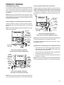
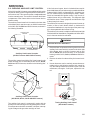
On GUIV-CA/DX and GUVA-AX models, a motor interface
board mounted on the control bracket is used to control
blower operation in 3 modes of operation. Fan only, cooling
speed and heating speed. Refer to the Airflow Charts in furnace Technical Manuals for details.
The cooling and heating speeds are adjusted by relocating
the jumper pins on the motor interface board.
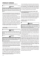
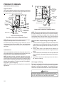
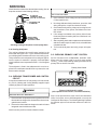
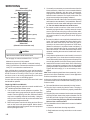
There is a LED, located on the blower interface board on
GUIV-CA/DX/FX and GUVA-AX models or on the integrated
ignition control on GCVA and GUVA-BX models, that serves
to indicate the airflow that the motor is supposed to be delivering, depending upon the positioning of the pin selectors
on the interface board on the GUIV-CA/DX/FX and GUVAAX models or on the DIP switches on the integrated ignition
control on the GCVA and GUVA-BX models. The number of
blinks multiplied by 100 yields the programmed CFM (Example: 10 Blinks x 100 = 1000 CFM). The indicated CFM
may vary, depending on the mode of operation and the signals being sent to the control board at the time.
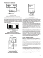
ECM/ICM Control Connections
Control functions (G, Y, Y1, Y2, W, W1, W2) may be active
at less than 1/2 control voltage. (i.e. 12 volts). Relay contacts on control functions must reliably switch low currents
(less than 5 MA). Some thermostats (with triac switches)
and Solid State Relays may allow enough "leakage" current
to turn on "G". Thermostats that "steal" power thru "Y" or
other functions are not compatible.
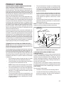
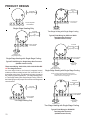
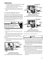
The ECM control interface can be as simple as a direct
connection to the thermostat. For example: "R" to "G" will
cause the fan to come at "Fan-Only" CFM, "R" to "G" to "Y"
will cause the fan to come on at Cooling speed and R to G
to W will cause the fan to come on at heating speed. The
ECM/ICM control requires a common connection from the
transformer (transformer common to C1, C2 on control). In
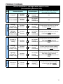
typical applications C1 and C2 will be tied together. Additional features can be utilized through the motor interface
control board, these features include; 2 Cool CFMs, 2 Dehumidification CFMs, 2 Heat CFMs, separate Fan-Only
CFM, and feed back information (CFM demand).